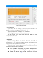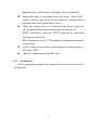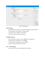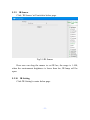
1
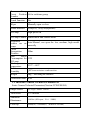
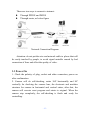
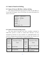
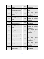
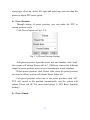
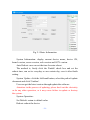
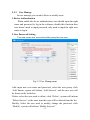
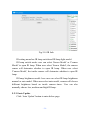
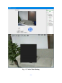
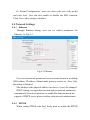
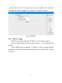
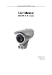
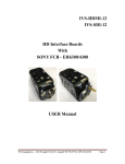
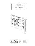
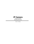
HD IP IR High Speed Dome Camera
User Manual
Read the user manual carefully before using this product
May 2012
-1-
Important Safeguards
1. During the course of transportation and storage, the product should be
avoided from incorrect operations such as heavy pressing, strong
vibration, soaking etc, which may cause damage to the unit.
2. The product is designed for wall-mount and pendant-mount
installation, it can not be installed upside-down. And the module should
be handled properly so as not to bring about mechanical problems
affecting the integrative functions of it.
3. Do not let any foreign objects or liquid infiltrate into the unit, which
may damage the machine.
4. Please follow all electrical standards for safety when it is being
connected and adopt the particular power supply which is provided with
the unit. The product adopts TVS-class lightning damage preventing
technology, which can effectively prevent such pulse signal damage
caused by lightning under 500W or electric surge. Video signal should
be kept enough distance from high voltage equipments and cables when
they are in transmission, and necessary steps should be taken to prevent
lightning damage or power surge.
5. No matter the unit is ruining or not, the camera should never be aimed
at the sun or object with extremely bright light. Otherwise, the camera’s
CCD might be permanently damaged.
6. There are no parts inside the unit which can be repaired by the users
themselves. When mechanical problems arise, do not be in a haste to do
any repairing, please refer to the User’s Manual to find the trouble. If
causes can not be located, please refer servicing to qualified
professionals. All servicing must be done by authorized personnel.
-2-
Table of Content
1. Technical Data................................................................................ - 6 1.1 Dome Camera Technical Data .............................................. - 6 1.2 Internal Camera Technical Parameters ................................. - 7 1.3 Internet Technical Parameters............................................... - 9 2. Characteristics .............................................................................. - 11 2.1 Dome Camera Characteristics ............................................ - 11 2.2 Network Characteristics...................................................... - 12 3. Network Connection Method................................................ - 12 3.1 Direct Connect Mode.................................................. - 12 3.2 Network Connect Mode.............................................. - 12 3.3 Power On ............................................................................ - 13 4. Camera Function Setting .............................................................. - 14 4.1 Camera Protocol, Bit Rate, Address Setting ....................... - 14 4.2 Camera Function Setting Form........................................... - 14 5、IE Log In Interface...................................................................... - 16 5.1 Login Home Page ............................................................... - 16 5.1.1 Device Log In ....................................................... - 16 5.1.2 Home Page Instruction.......................................... - 19 5.1.3 Home Page Instruction.......................................... - 19 5.2 System Setting .................................................................... - 23 5.2.1 Basic Information ................................................. - 23 5.2.2 User Manage......................................................... - 25 5.2.3 Serial Port ............................................................. - 26 5.2.4 Device Record ...................................................... - 26 5.2.5 Net Record ............................................................ - 28 5.2.6 Time Setting.......................................................... - 29 5.2.7 Multiple Device .................................................... - 30 5.2.8 System Status........................................................ - 32 5.2.9 IR Sensor .............................................................. - 33 -3-
5.2.10 IR Setting ............................................................ - 33 5.2.11 Auto Update ........................................................... - 34 5.2.12 System Log ............................................................ - 35 5.3Audio Video......................................................................... - 36 5.3.1 Video Channel ...................................................... - 36 5.3.2 Video Set............................................................... - 37 5.3.3 Video Mask........................................................... - 38 5.3.4 Audio Settings ...................................................... - 40 5.3.5 Extend Configuration............................................ - 40 5.4 Network Settings ................................................................ - 41 5.4.1 Ethernet................................................................. - 41 5.4.2 PPPOE .................................................................. - 41 5.4.3 DDNS Settings...................................................... - 42 5.4.4 Port........................................................................ - 43 5.4.5 Network Check ..................................................... - 44 5.4.6 Docking Platform.................................................. - 44 5.5 Alarm Setting ...................................................................... - 45 5.5.1 Alarm In................................................................ - 45 5.5.2 Motion Detect ....................................................... - 46 5.5.3 Linkage Setting..................................................... - 48 5.5.4 Alarm Linkage ...................................................... - 48 5.6 Local Setting....................................................................... - 49 6. PTZ Control Basic Function...................................................... - 51 6.1 Preset Setting and Calling................................................... - 51 6.1.1 Preset Setting ........................................................ - 51 6.1.2 Calling for Preset Position .................................... - 51 6.2 Special Function Setting and Calling............................... - 52 6.2.1 Left/Right Scan Setting......................................... - 52 6.2.2 360 Scan................................................................ - 52 6.2.3 Tour Group Setting ............................................... - 52 6.2.4 Pattern Scan Setting .............................................. - 53 -4-
7. FAQ .............................................................................................. - 55 -
-5-
1. Technical Data
1.1 Dome Camera Technical Data
Power Supply
Power
Consumption
Communication
Baudrate
Manually
Horizontal
Rotate Speed
Manually
Vertical Rotate
Speed
Horizontal
Rotate Range
Vertical Rotate
Range
Auto
Flip
Function
Speed
Auto-control as
per the changing
of zoom ratio
Left & Right
Scan
Left & Right
Scan Speed
360º Scan
DC15V±10%(4A)
25W(Open high light IR lamp)
4800bps(Fix)
0.5º~120º/S,max 350º/S when rotate to preset position
0.5º~60º/S,max 120º/S when rotate to preset position
360ºno limit rotate
0 º~90º
Auto-flip 180º when vertical 90°
The pan/tilt can automatically adjust the running speed
following the change of the zoom ratio
Yes
Low,Medium,High
Low,Medium,High
Pattern
Scan
4 groups
Number
Preset Position
128
Number
Tour
Group
4 groups
Number
-6-
Tour
Group
Preset Position 16 for each tour group
Number
Guard Function
Yes
Wiper
Manually open or close
Alarm Interface
4 ways in, 1 way out(optional)
IR Lamp
High-power IR
IR Lamp Control Sensor mode and camera mode
Brightness
control for IR
lamps
Facial
Recognition
Distance
Max
Power
Consumption for
IR Lamp
Working
temperature
Relative
Humidity
Weight
Auto/Manual, can open the low, medium, high model
manually
100m
13W
-25‐~60‐
≤95% no moisture condensation
6Kg(including the bracket)
Protection Grade IP66
1.2 Internal Camera Technical Parameters
Sonic Camera Technical Parameters(Version: FCB-EH6300)
Image Sensor
1/2.8-type ‘Exmor’ CMOS
Valid Pixel
3.27 Million
Minimum
Illuminance
0.095lux (ICR open,F1.6,50IRE)
Close-up
10mm(W)~1000mm(T)(default to 300 mm)
-7-
camera shooting
distance
Aperture value
F1.6(W)~F3.5(T)
Focus
Auto/Manual/Trigger
zooming rate
20 times Optical variable times, 12 times digital variable
times
focal distance
f=4.7mm(Wide-angle end) ~94mm(long distance)
image angle
55.4°(Wide-angle end) ~2.9°(long distance)
electronic
shutter
1/1 to 1/10,000 s,22 steps optional
White Balance
Auto/Manual/Indoor/Outdoor
Gain Control
Auto/Manual
Weight
About260g
Size(W×H×D)
50x60x87.9mm
Working
Temperature
-5°C to 60°C
Storage
Temperature
-20°C to 60°C
Max
Power
Consumption
3.8W
J20AH Camera Technical Parameters (Version: 3NCM86-J20AH)
Image Sensor
1/2.9″,2.43Mega CMOS Sensor
Valid Pixel
2.1 million
Communication
Interface
VISCA protocol (TTL)
Min Lightness
0.5lx (ICR 开, 1/30sec)
-8-
Synchronize
Method
Internal synchronize
Scan Method
2:1 progressive scanning
Aperture
Auto/Manual
Focus
Auto/Manual
Zooming Rate
20 times Optical variable times
Focal distance
f=4.7mm(Wide-angle end) ~94mm(long distance)
Image angle
59°(Wide-angle end) ~3.3°(long distance)
electronic
shutter
Auto/Manual
White Balance
Auto/Manual
Gain Control
Auto/Manual
ICR Switch
Auto/Manual
Mirroring
Up Down/Left Right
Image Adjust
Definition/contrast/color enhancement/brightness
Weight
About 260g
size(W×H×D)
90.3x50.3x60mm
Working
temperature
‐5‐~+60‐
Max
power
consumption
3W
1.3 Internet Technical Parameters
Processor
Switch
method
DavinciTMS320DM368
in Ethernet
-9-
Video
Compression
Standard
H.264
Audio
Compression
Standard
AMR,G.711
Max
Frame 25 Frame/S
Rate
Video
Resolution
1920*1080(1080P) , 720*576(D1) , 352*288(CIF) ,
176*144(QCIF)
Stream
Dual stream. Main stream can choose 1080P/D1, sub stream
can choose D1/CIF/QCIF
Video
Compression
Bit Rate
16Kbps~8Mbps
Audio
AMR:4.75Kbps~12.2Kbps;G.711:64Kbps
Compression
Bit rate
Image Delay
<200MS
Net Interface
RJ-45 10/100M Network adaptive
Internet
RTSP/HTTP/HTTPS//FTP/DHCP/MUDP/SMTP/CIFS/UPNP/PPPOE/
Protocol
NTP/DDNS
- 10 -
Front
End USB storage device can support maximum 500G, TF card
Storage Device support maximum 16G(optional)
Talkback
1 way MIC In input, 1 way Line out output(optional)
Function
Alarm
4 way in, 1 way out(optional)
Interface
Motion Detect Sensitivity 1~100% is adjustable, linkage alarm can be set
2. Characteristics
2.1 Dome Camera Characteristics
The cover is constructed with aluminum alloy, which ensures
compact structure, high shielding strength and excellent
heat-dispersion effect. The lower part of the unit is designed as
exposed, which effectively solve the heat-dispersion problem for
the camera module and the IR lamps etc parts.
Adopt wiper design for easy to clean the water or item from lens
and gain clear image
Adopt circus lifeline design to ensure the safety during installation
Built in anti fog device to avoid fogging inside and ensure the
image definition
Latest LED Array technology is adopted for the IR lamp, LED
Array has higher brightness, longer visible distance, more evenly
distributed light field and much longer lifespan
Driven by a stepper electric mortar, the unit runs smoothly, reacts
quickly and locates positions accurately
- 11 -
Adopt EEPROM data storage method, data will not be lost when
out of electricity
Adopt conductive slide design, which can rotate 360°, no
supervision dead zone
Support PTZ auto flip function(vertical 180°auto flip and
supervision)
Support focus ratio control function(PTZ rotate speed can be
adjusted base on lens zooming value)
2.2 Network Characteristics
1、 Standard H.264 video compression format
2、 Support 1080P,D1,CIF,QCIF video format, can output main and
sub stream at the same time
3 、Built-in Web Server, fully support IE browser to surveillance,
configure and mange device, simple and convenience to operate
4、 Dynamic bit rate control to ensure real time video transportation in
internet
5、 Support multiple users to view video and can set log in authorization
6、 Support two way speech talkback
7、 Support motion detect
8、 Support image snapping
9、 Support image parameters adjust
10、Support linkage alarm
11、Support local and front end record and playback
3. Network Connection Method
3.1 Direct Connect Mode
Connect the camera to PC by network directly.
3.2 Network Connect Mode
Can connect the camera to internet, user can log in the device
through client side software of browser.
- 12 -
There are two ways to connect to internet:
Through PPPOE and DDNS
Through router, as below figure
Network Connection Diagram
Attention: do not put the wire and network cable to places that will
be easily touched by people, to avoid signal unstable caused by bad
connection of lines and effect the quality of video.
3.3 Power On
1. Check the polarity of plug, socket and other connection, power on
after confirmation
2. Camera will do self-checking, rotate 360º horizontally and 90º
vertically for checking the camera lens, the electronic and machine
structure for camera in horizontal and vertical status, after that, the
camera will execute reset program and rotate to original. When the
camera stop completely, the self-checking is finish and ready for
controlling.
- 13 -
4. Camera Function Setting
4.1 Camera Protocol, Bit Rate, Address Setting
The setting for HD IP IR camera protocol, baud rate and address is
fix and can't be changed. After self-checking, the system information for
camera is as below:
Protocol: PELCO-D
BaudRate:4800bps
Address: 1
DataBit:8
StopBit:1
ParityCheck:No
4.2 Camera Function Setting Form
Tip: some special functions don't have coordinate command in
'PELCO-D' protocol, in order to control these functions, we have
switched the function for some common use command.Normally will
switch by 'change preset position/set preset position', this function will
be introduced in 5.1.3, below list the command switch form:
Invoke
Preset
Point No.
Function for Preset
Point
Invoke
Preset
Point
No.
Function for Preset
Point
130
Set left limit
195
Start the third tour
group
131
Set right limit
196
The fourth tour group
setting begin
- 14 -
132
Start left/right scan(low
speed)
197
The fourth tour group
setting over
133
Start
left/right
scan(medium speed)
198
Start the fourth tour
group
134
Start left/right scan(high
speed)
180
The
first
setting for
scan begin
group
pattern
184
The
first
setting for
scan over
group
pattern
185
Start the frist group
pattern scan
181
The second group
setting for pattern
scan begin
135
136
137
Start PTZ 360º scan(low
speed)
Start
PTZ
360º
scan(medium speed)
Start PTZ 360º scan(high
speed)
138
Stop PTZ auto scan
184
The second group
setting for pattern
scan over
140
The frist tour group
setting begin
186
Start the second
group pattern scan
141
The frist tour group
setting over
182
The third
setting for
scan begin
group
pattern
group
pattern
142
Start the first tour group
184
The third
setting for
scan over
190
The second tour group
setting begin
187
Start the third group
pattern scan
- 15 -
183
The fourth group
setting for pattern
scan begin
192
Start the second tour
group
184
The fourth group
setting for pattern
scan over
193
The third tour group
setting begin
188
Start the fourth group
pattern scan
194
The third tour group
setting over
150
Restart of camera
191
Stop PTZ auto scan
5、
、IE Log In Interface
5.1 Login Home Page
5.1.1 Device Log In
Firstly, set the IP address segment of PC the same as the Device's.
For example, the device IP address is 192.168.1.217, gateway
192.168.1.1. PC IP address should be 192.168.1.XX, gateway
192.168.1.1.
Open the IE browser, input default IP address in address column, or
visit through domain name if the domain name analytic function is in
use, input domain name will display log in dialog box, as Fig 1-1. If user
is not sure of the device address, can search it by using searching tool or
client side software.
- 16 -
Fig 1-1 Log In Interface
Original Status:
Default
Address
192.168.1.217
User Name
admin
operator
user
Password
admin
operator
user
Attention: use default user name to login successfully, then the user
will have authorization for all kinds of operations. It's
suggested that user to modify password after first log in for
security.
Click
or
can switch language
For using this software for the first time will need to do below
setting in IE.
For first use user, he needs to install OCX ActiveX, or can't view
video. Click Download OCXfile for installation. After successfully
downloading, click OCX icon
page will be shown up:
for installation, below
- 17 -
Click 'Install' and below page will be shown up.
- 18 -
Click 'Finish' to complete the installation of OCX
Input user name and password to enter IE home page.
5.1.2 Home Page Instruction
After log in will enter the IE homepage, as Fig 1-2:
Fig1-2 Home Page
5.1.3 Home Page Instruction
1、
、Tool Bar Instruction
Fig 1-3-1-1 Tool Bar
:Disconnect/Connect with device
: Snap the current image and save to local PC(default path
C:\IPCamera, user can modify it by local setting)
:Save the current video to local PC
:Record playback
:User and controller talkback
:Volume on/off
:Select the area that need to zoom in
:Zoom in the selected area
:Display full screen of the current image
- 19 -
:Log out
:Display alarm status
Click 'Playback' button and a new window will be open as below
figure.
Fig 1-3-1-2 Record Playback
Playback function includes search and play record:
Search record: user can search record by record time and type.
Select the begin and end time you want to search and choose
record type, including local record and front end record, under
each type there are alarm, schedule(PC doesn't have schedule
record function), manual record. When the setting is finished,
click 'Search',the record that suits the requirement will be listed
Play Record: select the record that you want to play, click
- 20 -
'Play' button or double click this record, record can be played
on four screens on the left
Use the tool bar on the top, you can pause, stop, slower or faster
the record,you can also do snap, play by sequence, open/close volume.
2、
、Video Format Instruction
Fig 1-3-2 Video Image Format
HD IP Camera support dual stream, main stream supports 1080P
and D1, sub stream supports D1, CIF, QCIF. In normal situation, 1080P
and D1 suit for LAN, CIF suits for WAN, QCIF suits for mobile phone
network. User can select stream according to actual use.
3、
、PTZ Control
Fig 1-3-3 PTZ Control
PTZ
control
includes
focus+(focus-),zoom+(zoom-),wiper
- 21 -
open(wiper close),up, down, left, right and auto loop, user can drap the
mouse to adjust PTZ rotate speed.
4、
、Preset Position
Through setting of preset position, user can make the PTZ to
certain position easily.
Click 'Preset' button as Fig 1-3-4.
Fig 1-3-4 Preset Position Setting
Add preset position: input the preset title and number, click 'Add',
the system will inform 'Preset add ok!'. (Different camera has different
range for preset position, user can set ti according to actual situation)
Delete preset position: click 'Delete' after select the preset position
you want to delete, system will inform 'Preset delete ok!'
Call preset position: select one of the preset position, click 'call',
PTZ will switch to the position automatically, and the system will
inform 'Preset call ok!' For more detail please '6. PTZ Basic Function
Setting".
5、
、Preset Guard
- 22 -
Fig 1-3-5 Preset Guard
Preset guard function: if user set a preset guard(a special preset
position) and enable this function, when the device is in no operation
status, it will execute guard position function after a period of time, PTZ
will move to the guard position.
Set guard position: select 'Enable Guard', select a preset position as
guard position, set the idle time, click 'Set' button and save the
parameters is ok.
5.2 System Setting
5.2.1 Basic Information
Basic information will display current system information, user can
execute software reboot, set default, auto reboot and so on. As Fig2-1.
- 23 -
Fig 2-1 Basic Information
System Information: display current device name, device SN,
kernel version, server version, web version and OCX version.
Auto Reboot: user can set the time for auto reboot.
The method is, firstly click the 'Enable' check box and set the
reboot time, can set to everyday or one certain day, save it after finish
setting.
System Update: click the left-hand button, select the path of update
document and click 'Confirm'.
User can get the latest version through update the software.
Attention: in the process of updating, please don't cut the electricity
or do any other operation, or it may cause failure to update or destroy
the system.
System Operation:
Set Default: return to default value
Reboot: reboot the device
- 24 -
5.2.2 User Manage
In user manage you can add, delete or modify users.
1.Device Authentication
When enable the device authentication, user should input the right
name and password to log in the software; disable this function then
user doesn’t need to input password, only need to input the right user
name to log in.
2.User Password Setting
User can create new user and set the group for new user.
Fig 2-2 User Management
Add: input new user name and password, select the user group, click
‘Add’ button, system will inform ‘Add Success!’ and the new user will
be shown in the list below.
Delete: select the user need to delete, click ‘Delete’, system will inform
‘Delete Success’, at the same time this user will be deleted from the list.
Modify: Select the user need to modify, change the password, click
‘Modify’, system will inform ‘Modify Success!’.
- 25 -
5.2.3 Serial Port
The setting for serial post is fixed and can’t be changed.
Fig 2-3 Serial Port
5.2.4 Device Record
Attention: this function will be validated when the camera has
internal TF card or connect with U disk.
1. Schedule Record Time Setting
User can set the front end record time through time setting.
Click the white box to select coordinate time, the color of the
selected box will changed to orange.
Attention: click the day on the left will select 24 hours of that day.
Click ‘All’ will select all, and all of the box will change to orange color.
Save the setting when it’s finished.
- 26 -
Fig 2-4 Device Record
2.Record manage
User can set the disk strategy in case of the space of disk is not
enough, it can be set to stop record of delete old file.
Set the size of record, the range is 1 to 15 minutes.
Set the length of alarm record when alarm occurs.
Set the record size, totally there are four kinds of size:
1080P,720P,D1,CIF,QCIF.
3.Disk Status
Connect storage device to device’s SD card slot and the
information of it will be shown, including partition, total capacity, used
capacity, free capacity and used percentage.
When the setting for above parameters is finished, device will start
recording if the free capacity is enough.
Click ‘StartRec’, record status will display ‘Manual Record’,
system begin to record, click ‘StopRec’to stop recording.
During the time of device record, system will do record
- 27 -
automatically, record status will display ‘Record Schedule’.
During the time of recording, user can select ‘Auto Flush’,
system will do auto flush for the status of storage device
automatically based on the time you set.
When the storage device is connected with device, there are
two ways to download documents from storage device:
HTTP Download: can use HTTP method to download
document to local disk
FTP Download: can use FTP method to download document
to local disk
Click ‘Capture’can save the current image to storage device in
the form of JPG.
‘Initialize’ button use for the SD card
5.2.5 Net Record
Net record function enable the storage device in network to be used
in front end.
- 28 -
Fig 2-5 Net Record
1.NFS Setting
Record Switch: to open or close the NFS remote record function.
Network path: input address for remote NFS
Username: the user name to log in NFS
Password: password for the username
2.SAMBA Setting
Record Switch: to open or close SAMBA record function.
Network path: input address for SAMBA
Username: the user name to log in SAMBA
Password: password for the username
5.2.6 Time Setting
User can select time zone and adjust date and time.
- 29 -
Fig 2-6 Time Setting
Zone Setting: select local time zone and click ‘Save’.
Date Setting: can synchronize the date with local PC, click ‘Save’
to save the setting.
NTP Settings: click the check box ‘Sync with NTP’, select one of
the server and save, then system time will synchronize with the selected
internet clock.
5.2.7 Multiple Device
- 30 -
Fig 2-7 Multiple Device
Here user can add multiple devices, after that, user can operate
multiple devices in home page.
Setting method: input the IP address, port, username, password and
related information in the column, select the right channel, click
‘Add’and return back to home page, then you can view and operate
several devices by only log in one of them.
Attention: to view several devices will require higher configuration
PC, to enable this function in low configuration PC may affect the
quality, user can select the No. of devices based on the situation of your
PC, system support maximum 9 devices to display at the same time.
- 31 -
5.2.8 System Status
System status display the system status currently.
Fig 2-8 System Status
Select the time interval for flush, or click ‘Auto
flush’, it can flush the system status automatically.
Below is the information that system status will display:
Sequence 1: display temperature information
Sequence 2: display CPU use status
Sequence 3: display clock CPU frequency
Sequence 4: display RAM use status
Sequence 5: display power on continuous time
Sequence 6: display program operate continuous time
Sequence 7: display system UPNP status
Sequence 8: display ROUTE information
Sequence 9: display DNS server information
Sequence 10: display the IP address and resolution
information of the video stream that connected with camera
- 32 -
5.2.9 IR Sensor
Click ‘IR Sensor’ will switch to below page.
Fig 2-9 IR Sensor
Here user can drag the mouse to set IR lux, the range is 1-100,
when the environment brightness is lower than lux, IR lamp will be
open.
5.2.10 IR Setting
Click 'IR Setting' to enter below page
- 33 -
Fig 2-10 IR Info
IR setting menu has IR lamp switch and IR lamp light model.
IR lamp switch mode: user can select 'Sensor Model' or 'Camera
Model' to open IR lamp. When user select 'Sensor Model', the camera
sensor will determine whether to open IR lamp. When user select
'Camera Model', the inside camera will determine whether to open IR
lamp.
IR lamp brightness model: here user can select IR lamp brightness
manual or auto model. When user select auto model, camera will choose
different brightness based on inside camera times. User can also
manually choose low, medium and high IR lamp.
5.2.11 Auto Update
Click ‘Auto Update’ button to enter below page.
- 34 -
Fig 2-11 Auto Update
In this page, click ‘open’ can begin to set the related parameters.
Setting the right server URL, port, username, password and inquire
time interval, system will do auto updated accordingly.
5.2.12 System Log
Click ‘SysLog’ to enter below page.
- 35 -
Fig 2-12 System Log
User can view system log here.
5.3Audio Video
5.3.1 Video Channel
Select Audio Video and enter video channel page as Fig 3-1.
。
- 36 -
Fig 3-1 Video Channel
For different network status, user can select different video
channel.
HD IT IP High Speed Dome Camera support dual stream, main
stream support 1080P and D1 video format, sub stream support D1,
CIF,QCIF video format, user can open or close stream according to
actual use and set related parameters. Playback fluency can choose
high, middle and low. Save the parameters after setting, then system
will require you to log in again.
5.3.2 Video Set
Here is to set the contents show on the image, mainly include:
device name, time and BPS.
- 37 -
Fig 3-2 Video Parameters
User can select show or hide the device name, time and BPS.
If user wants to show device name, he needs to input the name.
Click ‘Save’ after setting finish.
Attention: device name can’t exceed 12 characters.
5.3.3 Video Mask
Through area mask, you can protect personal privacy from not
display certain area in supervision video.
When setting video mask, firstly need to select the mask color,
which is in the form of number, and then select the sequence in index,
click ‘Set’ button, click ‘Area’ and drag the mouse to select mask
area(mask area can’t exceed 1/4 of the image). When the setting is
finished, user can show, hide or delete this mask.
- 38 -
Fig 3-3 Video Mask Setting
- 39 -
5.3.4 Audio Settings
User can adjust the volume input and output based on actual
situation, as Fig 3-4.
Fig 3-4 Audio Settings
Click ‘Save’ after the setting finish.
If user wants to return to default value, select ‘Default’ and save.
5.3.5 Extend Configuration
Fig 3-5 Extend Configuration
- 40 -
In ‘Extend Configuration’, user can select code size, code profile
and code level. User can also enable or disable the BNC function.
Click ‘Save’ after setting is finished.
5.4 Network Settings
5.4.1 Ethernet
Through Ethernet setting, user can set related parameters for
Ethernet. As Fig 4-1.
Fig 4-1 Ethernet
User can set network parameter based on actual situation, including
DNS address, IP address, Subnet mask, gateway and so on. ‘Save’ after
the setting is finished.
Mac address is the physical address for device, it can’t be changed.
DHCP setting: can open this function and get network parameters
automatically from local network, to enable this function needs the
support of DHCP server, please confirm with network administrator.
5.4.2 PPPOE
When setting PPPOE auto dial, firstly need to enable the PPPOE
- 41 -
switch, then select the network card, input username and password
provided by internet supplier, save after the setting is finished.
Fig 4-2 PPPOE
5.4.3 DDNS Settings
DDNS can map the dynamic IP address to a fix domain name.
Before setting dynamic domain name analyze , you need open the
switch.
Select DDNS service supplier, 3322.0rg or 9299.org, input DDNS
username and password and other parameters, save after finish setting.
As Fig 4-3.
- 42 -
Fig 4-3 DDNS Setting
5.4.4 Port
Select NetSetting and select Port to enter below page.
Fig 4-4 Port
WEB Port:the port use for log in device in IE
FTP Port:the port use for FTP upload and download
RTSP Port:real stream port, use for video stream transportation
- 43 -
Speak Port:the port use for speak talkback
Update Port:the port use for software update
UPNP Switch:Auto port mapping switch(need the support of
router)
5.4.5 Network Check
Fig 4-5 Network check
5.4.6 Docking Platform
Different upgrade programs have different docking platform, here
take industry docking platform for instance.
- 44 -
Fig 4-6 Docking Platform
Enter the server page, as above Fig 4-6, select to enable or disable
the accessing of server. Add the server address that coordinate with
platform, port and heartbeat period and save. After saving the right
parameter, server status will be displayed on the right, which can view
real time connection status for each server.
5.5 Alarm Setting
5.5.1 Alarm In
Select ‘Alarm In’, enter ‘Alarm Setting’ page and enter page as Fig
5-1.
- 45 -
Fig 5-1 Alarm In
Attention:
Click white column in time table, it will change to orange
color
Click the day on the left, the whole day will change to
orange color
Click ‘All’ will select all, the whole time table will
change to orange color.
5.5.2 Motion Detect
Select ‘Alarm Setting’ and enter ‘Motion Detect’,you will enter
below page for motion detect setting.
- 46 -
Fig 5-2 Motion Detect
Motion detect parameters: firstly click the check box to enable
motion detect function, then set the sensitivity(1~100, the higher the
sensitivity, the less motion is required to trigger recording). Click the
radio button in front of ‘Select’, press Ctrl button and drag the mouse
in the image to set motion detect area. Press the radio button in front
of ‘Display’ and above page will be shown, as Fig 5-2.
1.Motion detect time schedule: set the motion detect front end time
schedule can linkage motion detect alarm during selecting
time(including front end record, email sending, FTP uploading and so
on)
Attention:
Click white column in time table, it will change to orange
color
- 47 -
Click the day on the left, the whole day will change to orange
color
Click ‘All’ will select all, the whole time table will change to
orange color.
2.Save the parameters after setting finish.
5.5.3 Linkage Setting
Select ‘Alarm Setting’ and select ‘LinkAttr’, as Fig 5-3.
Fig 5-3 Linkage Setting
Alarm center parameters: set alarm center address and port, save
after setting finish.
Email Parameters: set the email server, username and password and
save, then system will send the alarm information to coordinate email.
FTP Client Parameter: firstly input the FTP server name, username
and password, FTP path and upload type, save after setting finish.
5.5.4 Alarm Linkage
Select ‘Alarm Setting’ and enter ‘Alarm Linkage’ page, as Fig 5-4
- 48 -
Fig 5-4 Alarm Linkage
Alarm input linkage: select input channel, alarm interval and
linkage option such as alarm center, Email, playsound and so on.
Motion Detect: set motion detect alarm time interval, select linkage
options, including alarm center, Email, record, FTPsend, play sound,
capture(save the current image in the form of picture and save in
mobile device) and so on.
Simulate Alarm: this is for replacing probe and other devices to
trigger alarm by pressing button.
5.6 Local Setting
Select ‘Local Setting’ to enter below page.
- 49 -
Fig 6-1 Local Setting
Local Storage Setting: firstly set the manual record time and then
storage path.
Pre Record Setting: open the pre record function for alarm record
in IE.
Alarm Linkage Record: click ‘Alarm Linkage Record’ can do
linkage record when have alarm. Set the record size and save is ok.
- 50 -
6. PTZ Control Basic Function
Fig 1-3-4 Preset Position Setting
6.1 Preset Setting and Calling
6.1.1 Preset Setting
Camera can set 128 preset position. User can move the PTZ to
surveillance place and zoom+ or zoom- to adjust the image size.
Input a number to represent for this preset position, and press ‘Add’
button to save the setting. Then the camera will save this
surveillance position and the setting parameters.
For instance: set No.1 preset position.
-
Move the PTZ to surveillance place and adjust the size.
Input 1 to ‘Preset Num’ and input preset title
Press ‘Add’ button to save this preset position, then the
information will be shown in ‘Preset Select’.
6.1.2 Calling for Preset Position
Input the preset No. in the text box after ‘Preset Num’, or click the
drop down list from ‘Preset Select’ to choose the position you want,
then press ‘Call’ button, PTZ will move to coordinate position
accurately based on the parameters set before(including PTZ horizontal,
vertical angle and lens variable value).
For instance: call No.1 preset position
- 51 -
-
Input 1 in the text box after ‘Preset Num’ or select one from
‘Preset Select’
-
Press ‘Call’ button
Camera execute new order, PTZ move, lens adjust and finally
locate in the accurate No.1 position
6.2 Special Function Setting and Calling
User can achieve left/right scan, 360º scan, pattern scan and camera
reboot through calling special preset position.
6.2.1 Left/Right Scan Setting
Input 130 in the text box after ‘Preset Num’, press ‘Call’ button,
the current position is the left limit point for left/right scan, input 131
and press ‘Call’ button, the current position is the right limit point for
left/right scan. When finish setting of the left/right limit point, input 132,
camera will begin to do low speed left/right scan, input 133 medium
speed scan and 134 high speed scan.
6.2.2 360 Scan
Input 135 in the text box after ‘Preset Num’, press ‘Call’ button,
camera will begin to do low speed 360º scan, input 136 for medium
speed 360º scan and 137 for high speed’s.
6.2.3 Tour Group Setting
6.2.3.1 The First Tour Group Setting
Input 140 in the text box after ‘Preset Num’, press ‘Call’ button,
camera will begin the first tour group setting, select one preset position
from ‘Play Select’, and press ‘Call’, then this preset position will be
added to tour group, for each tour group can add 16 preset positions,
after the adding finished, input 141 and the adding will be over, input
- 52 -
142 to operate the first tour group.
6.2.3.2 The Second Tour Group Setting
Input 190 in the text box after ‘Preset Num’, press ‘Call’ button,
camera will begin the second tour group setting, select one preset
position from ‘Play Select’, and press ‘Call’, then this preset position
will be added to tour group, for each tour group can add 16 preset
positions, after the adding finished, input 191 and the adding will be
over, input 192 to operate the second tour group.
6.2.3.3 The Third Tour Group Setting
Input 193 in the text box after ‘Preset Num’, press ‘Call’ button,
camera will begin the third tour group setting, select one preset position
from ‘Play Select’, and press ‘Call’, then this preset position will be
added to tour group, for each tour group can add 16 preset positions,
after the adding finished, input 194 and the adding will be over, input
195 to operate the second tour group.
6.2.3.4 The fourth Tour Group Setting
Input 196 in the text box after ‘Preset Num’, press ‘Call’ button,
camera will begin the fourth tour group setting, select one preset
position from ‘Play Select’, and press ‘Call’, then this preset position
will be added to tour group, for each tour group can add 16 preset
positions, after the adding finished, input 197 and the adding will be
over, input 198 to operate the second tour group.
6.2.4 Pattern Scan Setting
Input 180 in the text box after ‘Preset Num’, press ‘Call’ button,
operate the camera(camera control, lens control) to execute the first
pattern scan;track record;Input 181 in the text box after ‘Preset Num’,
press ‘Call’ button, operate the camera(camera control, lens control) to
- 53 -
execute the first pattern scan;track record;Input 182 in the text box after
‘Preset Num’, press ‘Call’ button, operate the camera(camera control,
lens control) to execute the first pattern scan;track record; Input 183 in
the text box after ‘Preset Num’, press ‘Call’ button, operate the
camera(camera control, lens control) to execute the first pattern
scan;track record; Input 184 in the text box after ‘Preset Num’, press
‘Call’ button to end the pattern pattern scan setting. Input
185,186,187,188 in the text box after ‘Preset Num’, press ‘Call’
button,camera will operate the first, second, third and fourth pattern
scan.
- 54 -
7. FAQ
1.
Can Not Visit Via Browser
Possible Reason(1)
: Internet is not connected
Solving Method: connect the PC to internet and check if it can
normal work, get rid of cable and virus
problem, till PCs can ping to each other.
Possible Reason(2)
: IP address is being occupied by other
devices
Solving Method:connect the camera to PC and reset a new IP
address
Possible Reason(3)
: camera and PC IP address not in the same
segment
Solving Method:set them to the same segment
Possible Reason(4)
: Camera breakdown
Solving Method:
return for repairing
2. Can Not Control Camera Via IE
Possible Reason(1)
: Ensure if the settings of address, protocol
and other parameters in 'Serial Port' are
coordinate with the camera dial-up.
Solving Method:
check the camera protocol, bit rate and
other parameters in 'Serial Port' and set them
right.
Possible Reason(2)
: Camera breakdown
Solving Method:
return for repairing
- 55 -