1
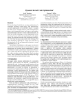
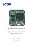
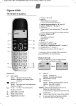
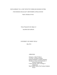
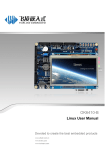
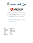
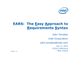
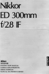
A Bare Machine Sensor Application for
an ARM Processor
Alexander Peter, Ramesh K. Karne and Alexander L. Wijesinha
Department of Computer & Information Sciences
Towson, MD 21252
[email protected], (rkarne, awijesinha)@towson.edu
Abstract- Sensor devices that monitor environmental changes in
temperature, sound, light, vibration and pressure usually run
applications that require the support of a small operating system,
lean kernel, or an embedded system. This paper presents a
methodology for developing sensor device applications that can
be directly run on the bare hardware without any need for
middleware. Such bare sensor device applications only depend
on the underlying processor architecture, enabling them to run
on a variety of devices. The methodology is used for developing,
designing, and implementing a temperature sensor application
that runs on an ARM processor. The same methodology can be
used to build other bare machine sensor device applications for
ARM processors, and is easily extended to different processor
architectures.
Keywords-bare machine computing,sensor devices,
architecture, application objects, direct hardware API.
ARM
I. INTRODUCTION
The popular ARM processor is used in mobile phones,
sensor devices, and other control applications. These
applications typically use an operating system (OS), lean
kernel, or they are part of an embedded system [1]. We
describe a methodology to develop bare ARM applications,
where the application directly communicates to hardware
without any middleware or OS. Previously, a variety of bare
PC applications have been built [2, 3, 4, 5, 6]. These
applications are based on the Bare Machine Computing
(BMC) paradigm, which was originally called the Dispersed
Operating System Computing (DOSC) paradigm [7].
The BMC paradigm allows an application programmer to
have sole control of the application and its execution
environment. When computing devices or hardware system is
bare, it could become ownerless, pervasive, adaptable, and reconfigurable to suit the needs of an application. The bare
hardware or system can be used by any user anywhere without
concern for sharing resources. A portable device such as a
USB flash drive can be used to carry the bare machine
application and run it on any bare machine. The BMC
paradigm enables computing to be polarized on applications
rather than computing environments.
This paper describes the approach and methodology used to
build a bare machine ARM application for a sensor device.
The methodology is illustrated by means of a temperature
sensor application that runs on an ARM development board
(ADB) [8]. We use U-Boot, the Universal Boot Loader, to
load and run the bare application. The U-Boot is the only tool
needed to bootstrap and load the application, which is
independent of any operating system, lean kernel, or
embedded system.
In order to build a bare machine temperature sensor device
application, it requires several components as shown in Fig. 1.
A brief functional description of this application is as follows.
The application is loaded from the SD Card interface (Label 9)
into memory using U-Boot. A temperature sensor (Label 1) is
plugged into the ADB to monitor the current room
temperature with a sensing granularity of 900 microseconds.
As the temperature changes, its value (Label 8) and a graphic
image (Label 7) is displayed on the LCD screen (Label 2). An
output console is used to debug the inner working of the ADB
and temperature (Label 3). An LED light (Label 4) provides a
visual indication of temperature sensor operation. A buzzer
(Label 5) is used to trigger an auditory alert based on a predefined temperature threshold. Also, the LCD screen color is
changed to red to provide a visual alert, with a button icon to
disable the buzzer via a touch screen interface (Label 6). The
ADB is used to illustrate the development of a bare
temperature sensor device application without any middleware
or kernel.
The rest of the paper is organized as follows. Background
and related work is presented in Section II. A development
methodology for building bare machine applications for ARM
sensors is described in Section III. The design,
implementation,and interface details together with code
snippets are provided in Section IV. Functional operation and
testing is discussed in Section V. The conclusion is contained
in Section VI.
Bare Application (8)
UART/Console
RS232 (3)
Touch Screen (6)
Bare
Graphics (7)
LED (4)
LCD (2)
Buzzer (5)
Temperature
Sensor (1)
SD Card (9)
Fig. 1. ARM Development Board (ADB)
978-1-4673-5208-6/13/$31.00 ©2013 IEEE
II. BACKGROUND AND RELATED WORK
Most computer applications require OS calls in some form.
These OS calls enable applications to access hardware
resources at run time. In contrast, bare machine applications
eliminate the OS by using their own bare interfaces to the
hardware [9]. These interfaces may, for example, enable
program load, screen display, mouse and keyboard access,
process management, and network or audio card control. A
given application only includes the interfaces that it needs. By
eliminating the OS, kernel, and all forms of intermediary
system software, the application is given full control of the
hardware. Details of a bare graphics application for an ARM
processor are given in [10]. In this paper, we describe a bare
application for a sensor device that runs on an ARM
processor.
Many approaches to eliminate OS abstractions or reduce OS
overhead have been proposed beginning with Exokernel [11].
OS-Kit [12] provides the components to build an OS,while
Tiny OS [13] is designed for sensor applications. Palacios
[14] is an example of a lean kernel.
Translating x86 code to run on ARM processors is the focus
of [15]. In [16, 17], the Java virtual machine is run directly on
hardware in an embedded system. BulkCompiler [18] is a
simple compiler layer that works with ISA primitives and
software algorithms.
The BMC approach differs from previous code
transformation/translation approaches in that it is based on
eliminating OS or kernel dependent code in applications. This
approach still has a dependency on the underlying
architecture. This dependency could be eliminated in the
future by developing a generic hardware API for various
architectures, and eventually including these interfaces in the
hardware. However, until the hardware API is standardized,
the BMC approach requires that the programmer write both
application and systems code as an integral part of an
application.
III. METHODOLOGY
A general high-level methodology for building bare
machine sensor device applications is shown in Fig. 2. This
methodology was used to construct the bare sensor ARM
application discussed in this paper. To build any bare sensor
ARM application, it is necessary to understand the various
ARM architecture interfaces and protocols such as GPIO
(General Purpose Input and Output), UART, USB, SPI, IC2
and SDIO. This involves both system and application level
programming as when building any bare application. In
particular, internal details, PIN configurations, and other lowlevel information obtained from the product datasheet are
needed to construct the appropriate bare interfaces for the
ARM sensor application. Also, an appropriate development
and hardware execution environment needs to be chosen to
build, test and debug bare applications since there is no OS
support. In some cases, an integrated development
environment may help to speed up the bare application
development process. Based on the type of sensor device,
appropriate ARM interfaces (GPIO, UART, USB, etc.) must
be selected to implement a given application. Furthermore, a
generic ARM API must be developed to make the applications
robust. In addition, an appropriate compiler and linker for the
programming language must be available to create the bare
application modules. Sensor application testing and validation
are especially challenging in a bare environment.
START
Understand peripheral protocol and interfaces to ARM
Architecture (GPIO, UART, USB, SPI, IC2 and SDIO)
Understand product spec/data sheet for a
given sensor device
Identify sensor device pin configuration that are relevant
to ARM Architecture peripheral protocol
Select a bare ARM sensor device platform for
development (ADB - ARM Development Board)
Identify ARM interfaces that are needed for
this sensor device
Design ARM interfaces API for the above interfaces
Design and implement sensor device
application using the above API
Test and validate the sensor device application
END
Fig. 2.Bare machine sensor development methodology
Details of the bare sensor application that was built using
this methodology are as follows. We selected a temperature
sensor device, specifically the model DS18B20U 1-Wire
Digital Thermometer [19], which has three leads (GND,
DQand VDD). The Samsung OK6410 ARM Development
Board [8] was used as the development platform. The sensor
device is plugged into ARM’s GPIO interface. The GPIO API
is needed to initialize and communicate with the GPIO
controller. A timer facility on the ADB is used to sample the
sensor device since it requires a timer API for this application.
Similarly, it is necessary to construct an API for the touch
screen (user interface, disable alerts), LCD (display, visual)
[20], UART/RS232 (console debugging), LED Controller
(monitoring sensor device), and buzzer (alert).
While this methodology is specific to the temperature sensor
ARM device, it can be modified easily for other applications.
Developing bare machine applications poses many challenges
as indicate above, since the programmer defines, architects
and implements all the necessary hardware interfaces needed
for the application. There is no middleware or OS/kernel of
any kind to support the application during execution. This is
different
from
developing
conventional
OS-based
applications.
IV.
DESIGN/IMPLEMENTATION AND INTERFACES
This section describes the interfaces required, its design and
implementation for the bare temperature sensor device
application.
A. Interfaces
Fig. 3 identifies the interfaces needed for developing a bare
temperature sensor device application. This figure illustrates
how the software API and external peripherals communicate
with the internal hardware. In this application, the software
API was designed and implemented for Touch-Screen, LCD
Display, UART/RS232, Timer, LED, Buzzer, and
Thermometer Sensor Device. The figure also indicates the
actual interfaces designed and implemented for each class of
API (e.g. LCD display (init(), clock_cycle(), write_frame()).
We designed and implemented 20 software APIs for this
application.
Internal Hardware
Samsung
OK6410 ADB
GPIO BANK
Software API
init, polling, read_touch()
ADC
GPIO_F
Touch Screen
init, clock_cycle,
write_frame()
GPIO_I
GPIO_J
GPIO_F
LCD Display
init, read, write char ()
LCD Display
UART/RS232
PWM – prescaler
GPIO_F
Timer
init, read, write, switch_state()
Timer
VDD – HI / LO
GPIO_M
LED
PWM – freq. ratio/timer
timer_pwm_init()
GPIO_F
Buzzer
DQ – reset, write, read
init, read_temp()
Sensor Device
(Thermometer)
Clock – VSync/HSync
Baud – rate, bits, parity
init, start, delay, stop()
Buzzer
Touch Screen
GPIO_A
UART/RS232
LED
Peripherals
GPIO_E
Fig. 3. System interfaces
Sensor Device
(Thermometer)
The GPIO object is the key element of this application. It
provides the internal implementation for the above software
APIs. Sample code snippets to illustrate the GPIO API
implementation is given in Fig. 4. The interfaces use macros
as defined in the #define statements. It can be seen that these
interfaces directly manipulate GPIO facilities. We used GPIO
banks A, E, F, I, J and M consisting a total of 63 (8, 5, 16, 16,
12, and 6) pins. The connectivity of these pins and the bank
registers are obtained from the SoC User’s Manual [8].
Details of the sample GPIO interface read_pin() in Fig. 4 are
as follows. The GPIO_BASE definition is a pointer to the
starting address of the GPIO banks. There are three basic
GPIO registers, which are crucial to the development of the
GPIO API. The GPIO Configuration Register is used to
initialize the pin for configuring it as an input or an output.
The GPIO_CON_BASE provides the definition for this
register. The GPIO Data Register is used to load or store the
data. The GPIO_DAT_BASE provides the definition for this
register. The GPIO Pull-up Register is used to provide an
impedance match to the connection. The GPIO_PUD_BASE
provides the definition for this register. In the bare sensor
application, all these GPIO resources are directly accessed and
managed by the programmer (and not by other middleware)
i.e., the programmer needs to control the hardware operation
of these registers in the application.
#define GPIO_BASE 0x7F008000
#define GPIO_PORT_BASE(port) (port+GPIO_BASE)
#define GPIO_CON_BASE(port) (GPIO_PORT_BASE(port))
#define GPIO_DAT_BASE(port)
(GPIO_PORT_BASE(port)+0x4)
#define GPIO_PUD_BASE(port)
(GPIO_PORT_BASE(port)+0x8)
#define GPIOREG(address) ((*((volatile unsigned*)address)))
static void conf_bank( GPIO_BANK bank, unsigned
value, unsigned mask ) {
GPIOREG(GPIO_CON_BASE(bank)) =
(GPIOREG(GPIO_CON_BASE(bank))
& ( ~mask )) | ( value & mask ); }
static void conf_pud_bank( GPIO_BANK bank,
unsigned value, unsigned mask ) {
GPIOREG(GPIO_PUD_BASE(bank)) =
(GPIOREG(GPIO_PUD_BASE(bank))
& ( ~mask )) | ( value & mask );}
static void write_pin( GPIO_BANK bank, unsigned pin,
unsigned value )
{
GPIOREG(GPIO_DAT_BASE(bank)) =
(GPIOREG(GPIO_DAT_BASE(bank))
& (~(1U<<pin))) | ((1U == value)<<pin); }
static unsigned read_pin( GPIO_BANK bank,
unsigned pin )
return ( (GPIOREG(GPIO_DAT_BASE(bank))
& ((1U<<pin))) != 0 );
Fig. 4. GPIO API
{
}
B. Design
The design and implementation of LED API init(), read(),
write(), switch_state() operations are illustrated in Fig 5. The
init() method uses the GPIO object to configure the state and
status of the GPIO_M bank. Here, the state can be HI or
LOW, the status is set to Output, and the switch_state() API is
used to change the LED state to on/off. Also, the read() API is
used to get the state of the LED, and the write() API is used to
set the state of the LED. Note that the LED API uses the GPIO
object
interfaces
such
as
gpio_driver_open(),
conf_pud_bank(), and conf_bank().
The read_pin operation takes two parameters bank and pin.
For example if the parameters are E and 5 respectively, data is
read from pin 5 in bank E, and the value is returned. The bit
shifting shown in the code is needed to select an appropriate
pin from the bank. The other interfaces are similar to this.
void init( void )
{
GpioDriver *gpio = gpio_driver_open();
//disable pullup/down for GPM0,1,2,3 - fields 2bit wide
gpio->conf_pud_bank( GPIO_M, 0x00 , 0xFF );
//GPM0,1,2,3 as Output - fields 4bit wide
gpio->conf_bank( GPIO_M, 0x1111, 0xFFFF );
//set pin states to HI => disable led's
gpio->write( GPIO_M, 0xF, 0xF );
}
void switch_state( LED_NUM led )
{
GpioDriver *gpio = gpio_driver_open();
unsigned state = gpio->read_pin( GPIO_M, led );
gpio->write_pin( GPIO_M, led, !state );
}
unsigned read(LED_NUM led )
{
GpioDriver *gpio = gpio_driver_open();
return gpio->read_pin( GPIO_M, led);
}
void write(LED_NUM led, LED_STATE state )
{
GpioDriver *gpio = gpio_driver_open();
gpio->write_pin( GPIO_M, led, state );
}
Fig. 5. LED Code Snippets
C. Implementation
The interfaces and sample code snippets shown in Fig. 4 and
Fig. 5 illustrate the simplicity of programming a BMC
application. These interfaces are self-contained and do not
require any other system libraries, kernel, or OS. The
application programmer controls all aspects of program
development. In BMC, a program consists of a single
monolithic executable referred to as an application object AO
[7]. It is possible to have one or more end user applications
programmed as a single AO.
We implemented the bare sensor device application in the
ARM GNU C/C++ language under the Eclipse development
environment. The application program consists of code for
main, gpio, display, gfx (graphics), adc_touch (touch screen),
led, thermo1820 (thermometer) as shown in Table I. The
source and header files for these functions along with their
code sizes are shown in the table. The number of lines of
source code including comments is 1509, and the header file
code is 355 lines. This is the complete code required to
execute the bare application at run time. There are no
additional system calls or libraries used at run time.
Source
File
TABLE I
BARE CODE SIZES
# Lines of
Header
Code
File
# Lines of
Code
start.s
14
n/a
n/a
main.c
62
n/a
n/a
gpio.c
136
gpio.h
177
display_sw.c
265
display_sw.h
29
gfx.c
634
gfx.h
81
adc_touch.c
159
adc_touch.h
14
led.c
78
led.h
44
thermo1820.c
161
thermo1820.h
10
D. OS vs. Bare Machine Interface Characteristics
In an OS-based system, the GPIO interfaces are more
complex and involve many components. The GPIO.C (Linux)
file hierarchy is shown in Fig. 6. The large number of levels
in the hierarchy and its interdependencies reflect the
complexity in an OS environment. Numerous header files,
which call other header files in the hierarchy, are also
required. In the figure, nodes indicate the header file or an
implementation file, and the links indicate the connectivity
between different files. This tree has 24 required nodes: IRQ,
Thread, Flags, Checks, File System, I/O Control Lock, Bit
Operation, Type Checks, Procedure Trace, and 29 required
inter-dependent links. In addition, it also has some optional
nodes and links. An OS-based system has to cover all possible
uses of an interface for generic application development. In
this case, GPIO.C provides an API for any type of application
that runs on an ARM processor under Linux.
In contrast, a bare machine sensor application only requires
the GPIO interfaces in Fig. 7, which are specific to this
application. There is no hierarchy (i.e., the BMC model is flat)
and the layers of complexity in the OS environment are
avoided. The BMC paradigm thus allows applications to be
completely autonomous (self-controlled, self-managed, and
self-executable) by removing the centralized control in an OSbased approach.
/linux/kernel/gpio.c
linux/init.h
linux/fs.h
linux/stddef.h
linux/string.h
linux/kernel.h
linux/proc_fs.h
linux/slab.h
linux/ioctl.h
linux/blk_types.h linux/limits.h
linux/magic.h
linux/atomic.h
linux/spinlock.h
asm/atomic.h asm-generic/atomic-long.h
asm/ioctl.h
linux/compiler.h linux/spinlock_up.h
linux/spinlock_api_up.h
asm/processor.h
linux/irqflags.h linux/preempt.h linux/stringify.h asm/barrier.h linux/rwlock.h linux/bottom_half.h asm/types.h
asm/irqflags.h linux/typecheck.h linux/linkage.h linux/list.h
linux/types.h
linux/thread_info.h
linux/spinlock_types.h
linux/bitops.h asm/thread_info.h linux/rwlock_types.h linux/spinlock_types_up.h linux/lockdep.h
Fig. 6. Linux GPIO Interface Structure
gpio.c
ok6410_bare_lib/gpio.h
ok6410_bare_lib/uart.h
ok6410_bare_lib/timer.h
Fig. 7. Bare machine GPIO interface structure
Fig. 8. Windows CE temperature application
An ARM application for the temperature sensor device that
runs on Windows CE as shown in Fig. 8 is used for comparing
with our bare application. It consists of three source files and
their respective header files: TEM_AppDlg, TEM_App, and
stdafx. The application does not include graphics, alarm, and
touch screen. When these files are compiled in a bare system,
where the system files (OS libraries) are excluded, there are 33
errors. These errors are related to Windows CE system calls,
definitions, and some constants. During compilation, the
system calls for Windows CE and related libraries are
included to form an executable that runs on an ARM
processor. In an OS environment, an application programmer
cannot directly access the underlying ARM facilities. In the
BMC system, the hardware interfaces as shown in Fig. 7 and
the ARM facilities in Fig. 4 and Fig. 5 are directly accessed
and managed by the bare ARM application programmer. This
is the main distinction between an OS-based and a bare
application.
V.
FUNCTIONAL OPERATION AND TESTING
The development environment for the bare machine sensor
device application is shown in Fig. 9. The ADB board is
connected to a Windows laptop using an RS232/UART cable.
No OS is loaded in the ADB. The laptop is used to load, test,
and debug the application. The temperature sensor device is
plugged into the ADB. The ADB consists of a power switch
and reset button in addition to the other components in Fig. 1.
The power switch is used to boot the application and the reset
button is used to restart the application.
As noted earlier, the C/C++ bare application is developed
under the “Eclipse” IDE, which is run on the laptop. We used
the Telnet Hyper Terminal on this machine to communicate
with the ADB. Fig. 9 also shows an ADB diagram with the
bare memory map. The map contains bareperipheral.bin
(application executable) and the images area. The images are
used to display some icons in the LCD (bare graphics). The
application is loaded at 0xc0008000 and the images data is
loaded at 0xc5000000.
U-Boot 1.1.6 is used to boot the ADB. When the system is
booted, it displays a user menu. We exit this menu using
option (e) so that no other software is loaded in the ADB (bare
ADB). In the U-Boot shell, the command (#dnw c0008000
bareperipheral.bin) is used to load the bin file. The
command (#dnw c5000000 imagefiles) is used to load image
files. Once all the code and data are loaded, the command (#go
c0008000) is used to run the bare application.
When the application starts, it first executes the start.s code.
This is a small ARM assembly code segment [21] that
functions as a bare boot program. The assembly code then
jumps to main(), which is the starting point of the C/C++
application in the binary file. The bare application program
senses the temperature and displays the output on the LCD
screen as shown in Fig. 1. Testing was performed to verify
that all functions in the application including buzzer, LED
display, touch screen, and sensor device output worked as
intended. The buzzer alarm activates when the temperature
reaches a threshold value set in the application. This alarm can
be disabled by a touch screen interface as shown in Fig. 1.
REFERENCES
[1]
Eclipse IDE
[2]
Terminal
Telnet
Console
[3]
RS232/UART
Cable
[4]
[5]
Samsung OK6410 - ADB (No OS)
bareperihperals.bin
Memory
ARM
CPU
start.s
main, gpio,
display,
graphics,
touch, led,
sensor device
[6]
0xc0008000
[7]
[8]
0xc5000000
[9]
images
GPIO
Power Switch
Reset
[10]
[11]
Sensor Device
[12]
Fig. 9. Bare ARM application development environment
[13]
VI. CONCLUSION
[14]
A novel bare machine temperature sensor application was
described in this paper. The application, which does not use
any OS, kernel, or embedded system, has a direct API to
communicate with and control the hardware. A methodology
to develop the sensor application for an ARM processor was
also given. In particular, the bare machine interfaces to build
sensor applications on ARM were identified, and internal
design/implementation details of the relevant hardware API
were presented. Functional operation and the bare machine
aspects of ARM were discussed. The development
methodology can be adapted to build other bare sensor ARM
applications, and bare applications that are portable across a
variety of mobile and pervasive devices with ARM processors.
ACKNOWLEDGMENT
We sincerely thank NSF and in particular the late Dr. Frank
Anger, who initially supported this work by funding through
SGER grant CCR-0120155. Without his encouragement, bare
machine computing concept and explorations could not have
been possible.
[15]
[16]
[17]
[18]
[19]
[20]
[21]
L. Edwards. “Embedded System Design on a Shoestring,” Boston:
Newnes, 2003.
L. He, R. K. Karne, and A. L. Wijesinha, “Design and Performance of a
Bare PC Web Server,” International Journal of Computer and
Applications, vol. 15, pp. 100-112, June 2008.
P. Appiah-Kubi, A. L. Wijesinha, and R. K. Karne. “The Design and
Performance of a Bare PC Webmail Server,” 12thIEEE International
Conference on High Performance Computing and Communications
(AHPCN), pp. 521-526, 2010.
A. Alexander, A. L. Wijesinha, and R. Karne, “A Study of Bare PC SIP
Server Performance,” 5th International Conference on Systems and
Networks Communications (ICSNC), pp. 392 – 397, 2010.
G. Ford, R. Karne, A. L. Wijesinha, and P. Appiah-Kubi, “The
Performance of a Bare Machine Email Server,” 21stInternational
Symposium on Computer Architecture and High Performance
Computing (SBAC-PAD), 2009.
B. Rawal, R. Karne, and A. L. Wijesinha. “Mini Web Server Clusters for
HTTP Request Splitting,” 13thInternational Confrence on High
Performance Computing and Comunication (HPCC), 2011.
R. K. Karne, K.V. Jaganathan, T. Ahmed, and N. Rosa, “DOSC:
Dispersed Operating System Computing,” 20thAnnual ACM Conference
on Object-Oriented Programming, Systems, Languages, and
Applications (OOPSLA), Onward Track, pp. 55-61, 2005.
S3C6410X/OK6410 RISC Microprocessor Rev 1.20 User's Manual.
Samsung Electronics Inc., 2009.
R. K. Karne, K. Venkatasamy and T. Ahmed, “How to run C++
applications on a bare PC,” 6thACIS International Conference on
Software Engineering, Artificial Intelligence, Networking, and Parallel /
Distributed Computing (SNPD), pp. 50 – 55, 2005.
A. Peter, R. K. Karne, A. L. Wijesinha and P. Appiah-Kubi, “The
Design and Implementation of Bare PC Graphics,”7thInternational
Multi-Conference on Computing in the Global Information Technology
(ICCGI) pp.315-320, 2012.
R. Engler and M.F. Kaashoek, “Exterminate all Operating System
Abstractions,” 5thWorkshop on Hot Topics in Operating Systems, p. 78,
1995.
The OS Kit Project, School of Computing, University of Utah,
http://www.cs.utah.edu/flux/oskit. Last Accessed Aug. 2012.
Tiny OS, Tiny OS Open Technology Alliance, University of California,
Berkeley, CA, 2004, http://www.tinyos.net/. Last Accessed Aug. 2012.
J. Lange et al., “Palacios and Kitten: New High Performance Operating
Systems for Scalable Virtualized and Native Supercomputing,” 24thIEEE
International Parallel and Distributed
Processing
Symposium
(IPDPS), 2010.
Y-S Hwang, T-Y Lin, and R-G Chang, “DisIRer: Converting a
Retargetable Compiler into a Multiplatform Binary Translator,” ACM
Transactions on Architecture and Code Optimization (TACO), Volume
7, Issue 4, p18-1:18-33, 2010.
M. Schoeberl, S. Korsholm, T. Kalibera, and A.P. Ravn, “A Hardware
Abstraction Layer in Java,” ACM Transactions on Embedded
Computing Systems (TECS), v.10 n.4, pp.1-40, 2011.
D. Simon , C. Cifuentes , D. Cleal , J. Daniels , D. White, "Java on the
Bare Metal of Wireless Sensor Devices: The Squawk Java Virtual
Machine," Proceedings of the 2nd International Conference on Virtual
execution environments, pp. 78-88, 2006.
W. Ahn, S. Qi, M. Nicolaides and J. Torrellas, “BulkCompiler: HighPerformance Sequential Consistency through Cooperative Compiler and
Hardware Support,” MICRO’09, pp. 133-144, 2009.
DS18B20 1-Wire Digital Thermometer with Programmable Resolution
Datasheet. Dallas Semiconductor Corporation, 2005.
WXCAT43-TG3 4.3’’ TFT-LCD with Touch Panel Module Product
Specification Document. WANXIN IMAGE Inc., 2008
W. Hohl. “ARM Assembly Language. Fundamentals and Techniques,”
Florida: CRC Press, 2009.