1
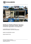
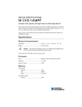
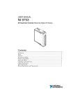
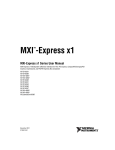
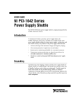
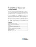
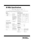
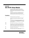
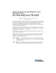
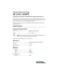
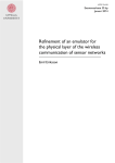
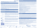
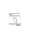
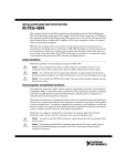
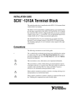
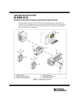
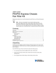
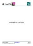
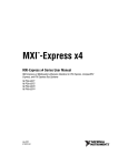
USER GUIDE SCB-19 19-Pin Shielded Desktop Connector Block This document describes how to connect and use the SCB-19 with the AUX I/O front panel connector on your National Instruments device. Figure 1 shows the parts of the SCB-19 connector block. Figure 1. SCB-19 Connector Block 2 2 1 1 SCB-19 2 Cover Screws Required Supplies In addition to the SCB-19 kit, you need the following supplies to connect and use your SCB-19 with your NI device: NI FlexRIO adapter module or other NI device with compatible 19-pin AUX I/O front panel connector SHH19–H19–AUX cable assembly (NI part number 152629-0x) Phillips #1 screwdriver 0.125 in. flathead screwdriver Shielded, multiconductor cable with 14–30 AWG wire Wire cutters Wire insulation stripper These supplies are not included in the SCB-19 kit. You must purchase these items separately. Note 2 | ni.com | SCB-19 User Guide Screw Terminal Diagram Figure 2 shows the interior of the SCB-19, including the screw terminals and their corresponding signals. Figure 2. Interior of the SCB-19 J2 J1 1 2 0 1 2 3 DIO PORT 0 3 0 1 2 3 DIO PORT 1 0 1 2 PFI 3 5V UPPER ROW SHOW SHOWN - LOWER ROW ALL GROUND S/N 4 5 1 2 3 DIO and PFI Screw Terminals Ground Terminals Wall Mounting Screw Holes 3 HT 20111 © COPYRIGHT 4 5 Cable Tie Loops Cable Tie Getting Started with the SCB-19 Complete the following steps to connect and use your SCB-19 with your NI device. 1. Install your NI device in your chassis. Refer to your device documentation for installation instructions. 2. Remove the four cover screws with a Phillips #1 screwdriver and open the top cover, as shown in Figure 1. 3. Connect wires to the screw terminals by stripping 6.35 mm (0.25 in.) of insulation, inserting the wires into the screw terminals, and securely tightening the screws with the flathead screwdriver to a torque of 0.5 N · m to 0.6 N · m (4.43 lb · in. to 5.31 lb · in.). Caution To ensure the EMC performance specified for the connected device, any wires connected to screw terminals that exit the enclosure must be shielded. NI recommends using a multiconductor cable with an overall shield. Terminate the cable shield to one of the PCB mounting screws. Note The top row of screw terminals corresponds to the DIO and PFI signals on the AUX I/O front panel connector. The bottom row provides ground terminals. SCB-19 User Guide | © National Instruments | 3 You can neaten the wires and provide mechanical support by sliding a cable tie through one of the slots shown in Figure 2, wrapping the cable tie around the wires, and tightening the cable tie. Tip 4. Close the top cover and tighten the four cover screws. Refer to your device documentation for maximum voltage specifications. Using voltages outside of the specified range could damage the SCB-19 and any devices connected to it. NI is not liable for any damage resulting from using voltages outside of the recommended range. Caution 5. Connect the SCB-19 to the AUX I/O front panel connector on your NI device using an SHH19–H19–AUX cable (NI part number 152629-0x) and tighten the target screw, as shown in Figure 3. Figure 3. SCB-19 Cable Connection 1 2 3 1 2 SCB-19 Target Screw 3 SHH19–H19–AUX Cable Assembly Although the AUX I/O front panel connector accepts a standard HDMI cable, a standard HDMI cable causes significant crosstalk between some channels. Use the SHH19–H19–AUX cable to minimize crosstalk. Caution When you have finished using the SCB-19, power off any external signals connected to the SCB-19 before you power off your computer. 4 | ni.com | SCB-19 User Guide SCB-19 Mounting Holes You can mount the SCB-19, either vertically or horizontally, on a DIN rail in an industrial environment. You can purchase a compatible DIN rail kit from NI using the part number 781740-01. The SCB-19 also has two screw holes for a generic wall mount. These wall mount holes are designed for use with a #4 or #6 panhead screw with a minimum length of 0.625 in. (15.88 mm). Figure 4 shows the screw holes locations on the bottom of the SCB-19. Figure 4. SCB-19 Mounting Screw Holes 1 2 2 Prod. of U.S.A. M/N: SCB-19 P/N: 151899A–01L S/N: 1111111 151899A 40 5V 2.5 in. (63.5 mm) 1 DIN Rail Mounting Screw Holes 2 Wall Mounting Screw Holes SCB-19 User Guide | © National Instruments | 5 Specifications Physical Dimensions .......................................................8.7 × 8.7 × 3.1 cm (3.4 × 3.4 × 1.2 in.) Weight ...............................................................355 g (12.5 oz) Connectors ........................................................H19 and screw terminals Environmental Operating environment .....................................0 °C to 55 °C, in accordance with IEC-60068-2-1 and IEC-60068-2-2. Relative humidity range....................................10% to 90%, noncondensing, in accordance with IEC-60068-2-56. Pollution Degree ...............................................2 Altitude .............................................................2,000 m Indoor use only. Storage environment Ambient temperature range ......................–20 °C to 70 °C, in accordance with IEC-60068-2-1 and IEC-60068-2-2. Relative humidity range............................5% to 95%, noncondensing, in accordance with IEC-60068-2-56. Clean the device with a soft, non-metallic brush. Make sure that the device is completely dry and free from contaminants before returning it to service. Note Shock and Vibration Operational shock .............................................30 g peak, half-sine, 11 ms pulse, in accordance with IEC-60068-2-27. Test profile developed in accordance with MIL-PRF-28800F. Random vibration Operating ..................................................5 Hz to 500 Hz, 0.3 grms Nonoperating ............................................5 Hz to 500 Hz, 2.4 grms, in accordance with IEC-60068-2-64. Nonoperating test profile exceeds the requirements of MIL-PRF-28800F, Class 3. 6 | ni.com | SCB-19 User Guide Safety This product meets the requirements of the following standards of safety for electrical equipment for measurement, control, and laboratory use: • IEC 61010-1, EN 61010-1 • UL 61010-1, CSA 61010-1 Note For UL and other safety certifications, refer to the product label or the Online Product Certification section. CE Compliance This product meets the essential requirements of applicable European Directives as follows: • 2006/95/EC; Low-Voltage Directive (safety) • 2004/108/EC; Electromagnetic Compatibility Directive (EMC) Online Product Certification To obtain product certifications and the Declaration of Conformity for this product, visit ni.com/certification, search by model number or product line, and click the appropriate link in the Certification column. Environmental Management NI is committed to designing and manufacturing products in an environmentally responsible manner. NI recognizes that eliminating certain hazardous substances from our products is beneficial to the environment and to NI customers. For additional environmental information, refer to the NI and the Environment Web page at ni.com/environment. This page contains the environmental regulations and directives with which NI complies, as well as other environmental information not included in this document. Waste Electrical and Electronic Equipment (WEEE) At the end of the product life cycle, all products must be sent to a WEEE recycling center. For more information about WEEE recycling centers, National Instruments WEEE initiatives, and compliance with WEEE Directive 2002/96/EC on Waste and Electronic Equipment, visit ni.com/environment/ weee. EU Customers * ⬉ᄤֵᙃѻક∵ᶧࠊㅵ⧚ࡲ⊩ ˄Ё RoHS˅ Ёᅶ᠋ National Instruments ヺড়Ё⬉ᄤֵᙃѻકЁ䰤ࠊՓ⫼ᶤѯ᳝ᆇ⠽䋼ᣛҸ (RoHS)DŽ݇Ѣ National Instruments Ё RoHS ড়㾘ᗻֵᙃˈ䇋ⱏᔩ ni.com/ environment/rohs_chinaDŽ (For information about China RoHS compliance, go to ni.com/environment/rohs_china.) SCB-19 User Guide | © National Instruments | 7 Where to Go for Support The National Instruments website is your complete resource for technical support. At ni.com/ support you have access to everything from troubleshooting and application development self-help resources to email and phone assistance from NI Application Engineers. National Instruments corporate headquarters is located at 11500 North Mopac Expressway, Austin, Texas, 78759-3504. National Instruments also has offices located around the world to help address your support needs. For telephone support in the United States, create your service request at ni.com/support and follow the calling instructions or dial 512 795 8248. For telephone support outside the United States, visit the Worldwide Offices section of ni.com/ niglobal to access the branch office websites, which provide up-to-date contact information, support phone numbers, email addresses, and current events. LabVIEW, National Instruments, NI, ni.com, the National Instruments corporate logo, and the Eagle logo are trademarks of National Instruments Corporation. Refer to the Trademark Information at ni.com/trademarks for other National Instruments trademarks. Other product and company names mentioned herein are trademarks or trade names of their respective companies. For patents covering National Instruments products/technology, refer to the appropriate location: Help»Patents in your software, the patents.txt file on your media, or the National Instruments Patents Notice at ni.com/patents. You can find information about end-user license agreements (EULAs) and third-party legal notices in the NI FlexRIO Readme. Refer to the Export Compliance Information at ni.com/legal/export-compliance for the National Instruments global trade compliance policy and how to obtain relevant HTS codes, ECCNs, and other import/export data. © 2012 National Instruments. All rights reserved. 375902B-01 Sep12