1
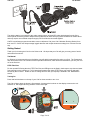
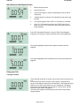
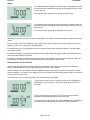
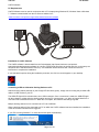
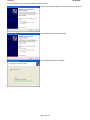
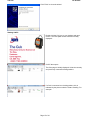
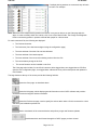
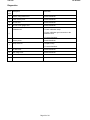
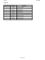
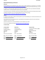
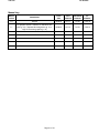
The CUB Instrument User Manual V1.1 For Sales & Service Contact 2650 E. 40th Ave. • Denver, CO 80205 Phone 303-320-4764 • Fax 303-322-7242 1-800-833-7958 www.geotechenv.com Part number: 871201 The Cub Ion Science The Cub Ion Science WARNINGS USER MANUAL: Read and understand this user manual completely before operating the Cub instrument. Intrinsically Safe: This Portable Cub has been designed and certified Intrinsically Safe. The Charger/Data Docking Station is NOT Intrinsically safe and must only be used in a safe area. STATIC HAZARDS: Do not use abrasive or chemical detergents to clean the Cub instrument as this may reduce the antistatic properties of the materials used, clean it using a damp cloth only. MATERIAL EXPOSURE The Cub must not be exposed to atmospheres known to have an adverse effect on Thermoplastic polyolefin or Anti-static PC/ABS. SERVICING: The Cub and Docking Station must be serviced in a Non Hazardous environment and by Ion Science Ltd authorised service centres only. Substitution of components may impair intrinsic safety. BATTERY CHARGING: The Cub is a rechargeable device and should only be recharged using the ISL Docking Station in a Non Hazardous environment. CHARGING PINS: Caution: Do not short circuit these two connections together else the internal fuse will blow and the Docking Station will need to be returned to the manufacturer for replacement. Proper Use If the equipment is used in a manner not specified by the manufacturer, the protection provided by the equipment may be impaired. Page 1 of 41 The Cub Ion Science Declaration of Conformity Manufacturer: Ion Science Ltd, The Way, Fowlmere, Cambridge, UK. SG8 7UJ Product: Cub Product description: Intrinsically safe photo-ionisation gas detector for detecting volatile organic compounds Directive 94/9/EC Required Coding - II 1 G Ex ia IIC T4 Ga Tamb. = -20ºC to +55 ºC Certificate Number- Baseefa11ATEX0027 IECEx BAS 11.0014 Notified body: Baseefa, Buxton Derbyshire , UK Report number: GB/BAS/ExTR10.0259/00 BAS/ExTR10.0259/01 BAS/ExTR12.0183/00 Standards EN 60079-0: 2007-10 Electrical apparatus for explosive gas atmospheres. General requirements EN 60079-11: 2006 Explosive atmospheres. Equipment protection by intrinsic safety "i" EN61326-1:2006 Electrical equipment for measurement, control and laboratory use - EMC requirements. Group 1, Class B equipment - (emissions section only) EN61326-1:2006 Electrical equipment for measurement, control and laboratory use - EMC requirements. Industrial location immunity - (immunity section only) EN50270:2006 Electromagnetic compatibility - Electrical apparatus for the detection and measurement of combustible gases, toxic gases or oxygen. Immunity Type 2 industrial environments. CFR 47:2008 Class A Code of Federal Regulations: 15 Subpart B- Radio Frequency Devices Unintentional Radiators Other Standards EN ISO 9001: 2008 EN 13980: 2002 Quality Management System - Requirements Potentially Explosive Atmospheres - Application of Quality Systems On behalf of Ion Science Ltd, I declare that, on the date this product accompanied by this declaration is placed on the market, the product conforms to all technical and regulatory requirements of the above listed directives. Name: Mark Stockdale Position: Technical Director Signature: Date: 20 June 2012 th Page 2 of 41 The Cub Ion Science ContentsWARNINGS 1 Declaration of Conformity 2 Contents 3 Statements 5 Responsibility for Use 5 IMPORTANT 5 Quality Assurance 5 Disposal 5 Calibration Facility 5 Legal Notice 5 Introduction to the Cub 6 Getting Started 7 The Manual 7 PTFE Filter Disc 7 Turning On 7 Turning Off 8 Batteries 8 Recharging the Battery Default Settings and Calibration 8 8 Introduction to the Display Screen 9 Using your Cub 9 Turning the Cub On 9 Alarms 10 Displaying other Screens and Data 10 PC Requirements 13 Installation of CubPC Software 13 Connecting a USB or Calibration Docking Station to a PC 13 Starting CubPC 15 Upgrading Firmware and Software 17 The Help Page 18 Getting Help Upgrading the Software Other Facilities Setting Docking Station Preferences 18 19 19 20 Actions On Dock History Calibration The Dock Page 21 21 21 21 Configuring a Cub 22 Name Sensor Units Clock Datalog Calibration Features 22 22 22 23 23 23 23 Page 3 of 41 The Cub Ion Science TWA STEL Sound Vibrate PID Alarms Screens Send to Instrument Downloading Data Logged Readings 23 23 23 23 23 23 23 25 Viewing Logged Data 25 Saving Logged Data to a CSV File 26 Viewing Details of Logged Data 27 Deleting all Logged Data 29 Software Disclaimers 30 Termination of Software Licence Disclaimer of Warranty No Right to Reply Limitation of Liability Governing Law Battery Charging 30 30 30 30 30 31 Recharging Battery 31 Charging Pins 31 Diagnostics 32 Maintenance 33 Calibration 33 Bump Test 34 Ingress of Water 34 PTFE Filter Disc (861221) 34 Lamp Cleaning 36 USE of PID Lamp Cleaning Kit A-31063 Cub Parts 36 37 Accessories 38 Instrument Warranty and Service 39 Warranty 39 Service 39 Contact Details: 39 Technical Specifications 40 Manual Log 41 Page 4 of 41 The Cub Ion Science Statements Responsibility for Use The Cub instrument detects a pre-selected range of gases which are potentially dangerous from both a poisoning and/or an explosive perspective. The Cub instrument has adjustable and selectable features allowing the detector to be used in a pre-selected way. Ion Science Ltd can accept no responsibility for the incorrect adjustment of features that cause harm or damage to persons or property. The Cub instrument is a personal safety device, it is the user’s responsibility to respond appropriately to an alarm situation. Inadequate performance of the gas detection equipment described in this manual may not necessarily be selfevident and consequently equipment must be regularly inspected and maintained. Ion Science Ltd recommends that personnel responsible for equipment use a regime of regular checks to ensure it performs within calibration limits, and that a record be maintained which logs calibration check data. The equipment should be used in accordance with this manual, and in compliance with local safety standards. IMPORTANT It is essential that the Cub is always used with a supplied 0.5 micron PTFE Filter Disc fitted to the front of the instrument. Without a filter, particles of debris and dust can be drawn into the detector inhibiting the function of the instrument. These filters are consumable and should be changed after every 100 hours of use. The frequency of replacement should be increased for dusty or moisture laden environments. Filters are available from your distributor or at http://www.ionscience.com/. Quality Assurance The Cub has been manufactured in compliance with the latest edition of ISO9001, which ensures that the equipment supplied to our customers has been designed and assembled reproducibly, from traceable components, and leaves Ion Science Ltd calibrated to stated standards. Disposal Dispose of the Cub, Docking Station and it’s components in accordance with all local and national safety and environmental requirements. This includes the European WEEE (Waste Electrical and Electronic Equipment) directive. Ion Science Ltd offers a take back service. Please contact us for more information. Calibration Facility Ion Science Ltd offers a calibration service including the issue of certification confirming calibration with equipment traceable to national standards. A Cub calibration kit is available from your distributor or service centre or at http://www.ionscience.com/. Ion Science Ltd recommends annual return of all instruments for yearly service and calibration. Legal Notice Whilst every attempt is made to ensure the accuracy of the information contained in this manual, Ion Science Ltd accepts no liability for errors or omissions, or any consequences deriving from the use of information contained herein. It is provided "as is" and without any representation, term, condition or warranty of any kind, either express or implied. To the extent permitted by law, Ion Science Ltd shall not be liable to any person or entity for any loss or damage which may arise from the use of this manual. We reserve the right at any time and without any notice to remove, amend or vary any of the content which appears herein. Page 5 of 41 The Cub Ion Science Introduction to the Cub The Cub is a personal portable gas detector that detects a pre-selected range of Volatile Organic Compounds (VOC's) which can be dangerous from both a poisoning and explosive perspective. The Cub uses a Photo-Ionization Detector (PID) to measure gas concentrations. The patented fence electrode technology minimises the effects of moisture and contamination, avoiding the need for compensation. The Cub is used to check for conformity of short-term exposure levels (STEL) time-weighted averages (TWA) that are specific for particular hazardous environments (for example EH40 in the UK and OSHA in the USA). In this mode of operation STEL's and TWA's are continually calculated and compared to levels set in the instrument. Alarm conditions can be indicated by a programmable combination of an audible alarm, vibration and bright flashing LEDs. Red and Orange LED's indicate High and Low conditions respectively. The Cub can be used with three types of Cub Docking Stations, these docking stations are for indoor use only, are not Intrinsically Safe so must only be used in a safe area. Cub Recharging Docking Station simply used to recharge a Cub’s battery equipped with LED to clearly indicate power Cub Recharging and USB Docking Station used to recharge a Cub’s battery connects via a standard USB cable in order to transfer logged readings from a Cub to that PC equipped with LED’s to clearly indicate power and USB connection Cub Recharging and Calibration Docking Station can be used to perform the functions of both the above docking stations, and also to calibrate a Cub using CubPC equipped with LED’s to clearly indicate power, USB and calibration conditions The source of power for the docking station is either :1. Through the IEC mains plug limited to a nominal of 95Vac to 240Vac +/-10% input range. The inlet fuse is Mains ceramic 1A timelag (anti-surge 20 x 5mm cartridge. 2. Through the rear DC Skt connected to a 12V car auxiliary/(cigarette lighter) outlet. Page 6 of 41 The Cub Ion Science The docking station is connected to the mains supply using a universal IEC mains lead plugged into the flying socket part of the docking station. Multiple docking stations can have their flying leads connected as shown above and only require one universal computer supply cord for all docks connected together. CubPC is a software program that enables users to calibrate a Cub (via a Cub Calibration Docking Station) from their own PC. CubPC also helps manage logged data files and multiple instrument settings in a clear and concise way. Getting Started Thank you for choosing the Cub from Ion Science Ltd. We hope that your Cub will give you many years of active and trouble-free service. The Manual Ion Science Ltd recommend that you familiarise yourself with this manual before using your Cub. The ‘Statements’ and ‘Introduction to the Cub’ sections contain important information, which should be read before you turn your Cub on for the first time. PTFE Filter Disc For the quoted IP65 rating then the PTFE Filter Disc and O’Rings must be fitted in both caps to stop dust and water from entering into the instrument. For full stated performance then these PTFE Filters only need be changed if blocked by dust or water. Details on how to change and fit a filter (as required) is detailed in the ‘Maintenance’ section. Turning On Press and hold the button on the top of your Cub for three seconds to turn it on. The Cub will beep when the button is first pressed. A progress bar is shown on the display screen as the unit switches on, with segments being added to it from left to right. Page 7 of 41 The Cub Ion Science Turning Off Press and hold the button on the top of your Cub for three seconds to turn it off. A progress bar is shown on the display screen as the unit switches off, with segments being removed to the bar from it right to left. Batteries Fully charge the Cub before use. The rechargeable 3.7V Li-Ion battery in your Cub cannot be replaced, but should last for the lifetime of the instrument. Recharging the Battery Cub instruments leave the factory with the battery fully charged. However prolonged periods of storage may result in the battery discharging. We recommend charging the instrument for at least four hours before use. See the ‘Recharging’ section of this manual (page 30). Default Settings and Calibration Cub instruments leave Ion Science Ltd pre-set for gas type Isobutylene. Instruments are factory calibrated against isobutylene and all response factors are equivalent to this. CubPC The gas type and associated calibration can be changed using the CubPC software and a Cub Calibration Docking Station. Ion Science Ltd recommends that you load the software supplied with your instrument and set up your Cub according to the instructions in the ‘CubPC Software’ section of this manual. Page 8 of 41 The Cub Ion Science Introduction to the Display Screen 1. Battery charge indicator 2. Detected gas level 3. Gas level units (ppm or mg/cm3, depending on how the Cub is configured) 4. “Volatile Organic Compound” This indicates the gas sensor type selected 5. This symbol appears when a STEL or TWA alarm is exceeded. 6. If the “TLV” (Threshold Limit Value) and “STEL” (Short Term Exposure Limit)” icon is present on-going calculated values are being displayed. If the “PEL (Permissible Exposure Limit) and TWA (Time-Weighted Average) icon is present on-going calculated value is being displayed. The symbol highlighted indicates that a high level alarm has been triggered. The symbol highlighted below indicates that a low level alarm has been triggered. Using your Cub Turning the Cub On Press and hold the button on the top of your Cub for three seconds to turn it on. The Cub will beep when the button is first pressed. A progress bar is shown on the display screen as the unit switches on, with segments being added to it from left to right. When the Cub is switched on, the display screen will be illuminated with a green light for a few seconds, and the firmware version number is displayed. The screen will display the detected gas level and the current battery charge condition. Page 9 of 41 The Cub Ion Science Alarms If the detected gas level triggers a high level alarm, the display screen will be illuminated with a flashing orange light, and the lights on the top of the unit will flash red. The high level alarm symbol will be displayed on the screen. If the detected gas level triggers a low level alarm, the display screen will be illuminated with a flashing red light, and the lights on the top of the unit will flash red. The low level alarm symbol will be displayed on the screen. Depending on how the Cub was set up (see Configuring a Cub, below), an alarm may also sound and the unit may vibrate. If the alarm latch is set (see Configuring a Cub, below), these alarm indications cannot be switched off except by switching off the Cub, or placing it in a docking station. If the alarm latch is not set, pressing the button once will turn off the alarm sound and vibration. The alarm lights will continue to flash. If the button is pressed a second time while gas levels are high enough the trigger an alarm are still detected, the alarm sound and vibration will resume. If the button is pressed a second time and gas levels are no longer high enough to trigger an alarm, the lights will stop flashing. The display screen will be illuminated with a green light for a few seconds. Displaying other Screens and Data Cycle through the different the Cub data screens by pressing the button. When a new screen is accessed the display is illuminated with a coloured light which will turn off after a few moments. When the display is lit up, a different screen is displayed every time the button is pressed (except when an alarm has been triggered - see above). If the display is not lit up, the button must be pressed again to light it up before the screens can be cycled through. The screens you can view are listed below in the order that they are accessed. The gas level indicator screen. This is the screen which is displayed by default when a Cub is turned on. The screen lights up green when it is accessed. This screen shows the on-going live TLV / STEL calculation and the backlight illuminates light blue for around 10 seconds. If an alarm state is triggered the user should withdraw from the hazardous environment and act in accordance with national safety regulations. Page 10 of 41 The Cub Ion Science This screen shows the on-going live PEL / TWA calculation and the backlight illuminates dark blue for around 10 seconds. If an alarm stat is triggered the user should withdraw from the hazardous environment and act in accordance with national safety regulations. The next screen displays the current time. The screen lights up green when it is accessed. The next screen indicates the low alarm level set for the Cub. The screen lights up orange when it is accessed. The next screen indicates the high alarm level set for the Cub. The screen lights up red when it is accessed. The next screen displays the current temperature. The screen lights up green when it is accessed. Page 11 of 41 The Cub Ion Science This is the remote calibration screen which allows the Cub to be calibrated in the field using a portable gas supply. To enter the remote calibration routine, Press and hold the on/off button until a confirmation beep is heard. Please note: To carry out a remote calibration the Span gas type and concentration must be setup on the configuration screen within CubPC and sent to the Cub instrument. The following equipment is also required. * A clean ambient air supply or a bottle of compressed synthetic air fitted with a 0.3Liter per minute flow regulator * A bottle of compressed Span gas fitted with a 0.3Litre per minute flow regulator. * Remote calibration adaptor * Suitable pipe to connect gases to the remote calibration adaptor. Zero calibration is indicated by the ‘0’ on the left of the screen. Supply clean air to the Cub sensor and then press the On/Off button. The number on the right of the screen counts down from 9 to 0 to indicate progress. The battery segments also fill to indicate progress. At the end of this stage the screen changes to the span screen. Span calibration is indicated by an ‘S’ on the left of the screen. Supply span gas to the Cub sensor and then press the On/Off button. The number on the right of the screen counts down from 9 to 0 to indicate progress. At the end of the calibration sequence the Cub will revert to the general VOC. IMPORTANT: After carrying out a calibration always bump test your gas detector using it. This is done by supplying calibration gas to the sensor and ensuring the correct level is displayed. Page 12 of 41 The Cub Ion Science CubPC Software PC Requirements CubPC Software must be used in conjunction with a PC or laptop using Windows XP, Windows Vista or Windows 7. Software is downloaded from the Ion Science website from:www.ionscience.com/product-support/downloads/instrument-software Installation of CubPC Software The CubPC software is downloaded from the Cub webpage (http://www.ionscience.com/productsupport/downloads/instrument-software) in a zip file. Extract all the files from the zip file and click on the setup .exe file (which will be indicated with the Cub icon). The installation wizard will then start. Follow the onscreen instructions to complete the installation. If you selected this option during the installation procedure, the Cub icon should appear on your desktop. Connecting a USB or Calibration Docking Station to a PC With the docking station powered on (the Charge LED should be green), simply connect it using the provided USB cable to a USB socket on your PC. The USB LED light will be red when there is no USB connection. Once a connection is made, the USB LED light will then change to yellow while the docking station and the PC communicate - e.g. while any logged data from a connected Cub is transferred to the PC. When this is complete, the USB LED will change to green. Multiple docking stations can be connected to a PC via a USB hub. When a docking station is first connected to a PC on which the CubPC software has been installed, the installation of the device driver software will be triggered. If your PC is running Windows 7 or Vista, this will take place automatically: Page 13 of 41 The Cub Ion Science If it is running XP, the Found New Hardware Wizard is started: Click any of the above options as required and then click ‘Next’. Click ‘Install the software automatically’. The wizard then installs the software. Page 14 of 41 The Cub Ion Science Click ‘Finish’ to close the wizard. Starting CubPC Double click the Cub icon on your desktop and open CubPC. The Cub splash screen will then be briefly displayed: CubPC then opens. The Cubs page is initially displayed. It lists the currently and previously connected docking stations. If a Cub is connected to a docking stations, this is indicated by the picture under the ‘Status’ heading. For example: Page 15 of 41 The Cub Ion Science If multiple docking stations are connected, they will each be listed. For example: Note: Where there are multiple docking stations connected, it may not be obvious on the Cubs page which is which. In order to identify which unit is which, click in one of the ‘Status’ fields. The Charge and Diagnostic LEDs on the docking station in question will both flash purple for a few seconds. For each connected Cub, the following are displayed: The Cub serial number The Cub name (if one has been assigned using the configuration page) The time and date of that the Cub was last calibrated The time and date of the last bump test The time and date of the most recent datalog received from the Cub The current battery charge of the Cub The current firmware version installed on the Cub. The Cubs page also includes, for each Cub, buttons to delete logged data, save logged data to CSV files, open the Cub configuration page, view logged data, calibrate the Cub, perform bump tests and update the Cub firmware. The large buttons at the top of the screen provide the following facilities: Opens the Cubs page, as described above. Opens the Help page, which displays general information on the CubPC software and provides accessed to technical support and documentation. Opens the Preferences page, used to specify the actions taken when a Cub is connected to a dock and history and calibration preferences. Used to view details of the connected docks and perform purges and firmware updates. Used browse back and forward through the CubPC pages you have viewed. Page 16 of 41 The Cub Ion Science Used to close CubPC. Additional data and facilities for a Cub can be accessed by click the + symbol at the next to the serial number of that Cub. The additional details are then displayed: The Calibration column displays the zero and span levels that the Cub is calibrated to. The Datalog column displays the minimum and maximum levels of gas, and the detected STEL and TWA levels recorded in the last data log. The column also displays an additional button for viewing details of the last data log (see Viewing Details of Logged Data). Upgrading Firmware and Software Before you do anything else you, you may wish to check whether any upgrades are available for either the Cub, the docking station or the software. Software updates are installed using the Help page (see below). To update the Cub firmware, click this button on the Cub page, under the firmware heading: . Note that upgrading the firmware of a Cub will result in any logged data on that Cub being automatically deleted. To update the docking station firmware, click the same button on the Dock page. If the firmware is up to date, nothing will happen. If a newer version is available, it will then be downloaded and installed on the equipment (an internet connection is required). A progress indicator will be displayed in the Firmware field while the upgrade is in progress. The new firmware version will then be displayed in the field. Page 17 of 41 The Cub Ion Science The Help Page Click this button to open the Help page: . The current software version is displayed at the top of the page, along with copyright information, who is it licensed to etc. Getting Help The ‘View Manual’ button opens this manual. If you can’t find the help you need in this manual, you can get help in two further ways. Page 18 of 41 The Cub Ion Science If you want to send a question to Technical Support, click ‘Contact Technical Support’. The following page is then displayed: Complete the form, making sure you enter your email address and the instrument number, and click ‘Send’. You can attach a file to your message via the ‘Add File…’ button. If you to access our support web page, click ‘Web Support’. The page will then be displayed. It lists our network of authorised service centres and describes the services they offer. Upgrading the Software If a newer version of the software is available, this is stated in the lower-left section of the page. To install the newest version, click ‘Install Upgrade’. The install will then take place. The old version of the software will automatically shutdown and replaced by the new version, which will then start up automatically. Other Facilities The Adobe Website button opens the Adobe Reader download page. It is recommended that this manual is viewed using Adobe Reader. To view the release notes for the software, click ‘View Release Notes’. A new window is then displayed in which the release notes can be viewed. Page 19 of 41 The Cub Ion Science For example: To check to see if an upgrade is available, click the ‘Poll Website’ button. If no upgrade is available nothing will happen. If an upgrade is available, details of the new version will appear in the text area to the left of the button. Setting Docking Station Preferences Click this button to open the Preferences page: . Page 20 of 41 The Cub Ion Science When you place a Cub in a docking station, logged data is automatically copied to the connected PC. Use this page to control what else happens automatically when you place a Cub in a docking station, and to specify history and calibration settings. Actions On Dock 1. If when a Cub is placed in a calibration docking station and logged data is to be automatically written to a .CSV file on the connected PC, tick the first checkbox. Use the ‘Browse’ button to specify the folder to which .csv files are to be written. Note that this is in addition to the automatic copying of logged data to the PC mentioned above. Such data may be viewed using CubPC, but it is encoded and may not be edited. Data transferred to CSV files may be freely edited, using Microsoft Excel for example. 2. If logged data is to be deleted from a Cub, click the second checkbox. If the first checkbox is also checked, this will happen after it is written to a .csv file. 3. If the time and date on the Cub is to be automatically synchronised with that on the PC to which the docking station is connected, tick the third checkbox. 4. If firmware on a Cub is to be automatically upgraded when placed in a docking station (if a newer version is available), click the fourth checkbox. Note that this will result in any logged data on the Cub being automatically deleted. 5. If the Cub is to be automatically bump tested when placed in a docking station, click the fifth checkbox. See page 34 for details of how to perform a bump test. If the bump test detects that the readings are outside the set minimum or maximum sensitivity limits (see Configuring a Cub), and the second checkbox in this step is checked (the one next to this symbol: instrument is automatically recalibrated. 6. ), the If all data is to be deleted from a Cub when it is placed in a docking station, click the sixth checkbox. Note that all data on a Cub is automatically downloaded and stored on the connected PC when it is docked. History If logged data more than a certain number of days old is to be deleted from the PC, tick the checkbox in the ‘History’ section of the page and enter the number of days in the field next to it. Calibration In the Calibration section, enter for zero gas and span gas the number of seconds that zero and span gas is to be sent to a connected Cub when it is being calibrated. It is recommended that a bump test be performed after changing these settings. The Dock Page Click this button to open the Dock page: . Use this page to view details of the connected docks and perform purges and firmware updates on docks. The page lists all connected docking stations. The Dock field displays the serial number of each dock. The Status field indicates whether or not a Cub is attached to a dock, as explained above (see Starting CubPC). Page 21 of 41 The Cub Ion Science The Firmware field displays the current version of the firmware installed on the dock, and contains a button to upgrade it to the newest version (see Upgrading Firmware and Software). Buttons displayed in the Purge field are for diagnostic use only. Configuring a Cub To configure a Cub, click the button on the Cubs page for that Cub. The following page is displayed: Name If required, enter a name for the Cub in this field. Sensor Displays the sensor type. Units 3 The units of measurement may be chosen as parts per million (ppm) or milligram’s per cubic metre (mg/m ). Page 22 of 41 The Cub Ion Science Clock Set the time and date and tick the checkbox to the right of these fields to set the time on your Cub. Alternatively, tick the lower box to synchronise your Cub with the time on your computer. Datalog Use this area to set the interval between readings. The minimum time permitted is one second. Calibration From the drop-down list, select the gas that the Cub is calibrated for. Cub offers two-point calibration (zero to a specified concentration). To define the span that the Cub is calibrated for, in the ‘Span’ field, enter the concentration in ppm. The calibration procedure is detailed in the ‘Maintenance’ section of this manual. Features Low sensitivity Cubs can be upgraded automatically via an internet connection. The customer can purchase an upgrade from his local distributor or supplier. Once the upgrade has been purchased the instrument must be connected to a computer running the CubPC software. The Cub instrument will then be automatically upgraded, via the internet connection. TWA STEL Select the appropriate regulatory code to which you are working using the radio buttons. In the ‘TWA Alarm’ and ‘STEL Alarm’ fields, enter more different (i.e. more stringent) TWA and STEL alarm levels if required. Sound If there is to be a sound when the button on the Cub is pressed, tick the first checkbox. If there is to be a sound when there is an alarm on the Cub, tick the first checkbox. Sound volume is adjusted with the slider. Tick the ‘Alarm Latch’ checkbox if an alarm is to continue to sound after the conditions that triggered the alarm are no longer present. Note: Unchecking this box means the alarm can be reset by pressing the on/off button twice. The first press silences the audio alarm, the second press stops the LED’s flashing. Vibrate If, when there is an alarm, the Cub is to vibrate, select the second radio button. If not, select the first. PID Select the PID lamp type from the two options. Ensure that the lamp selected is the same as that fitted in your Cub. Alarms In this section enter the high and low alarm levels for the selected gas. Screens In this section tick and un-tick the checkboxes to specify which screens are displayed in the Cub. Refer to ‘Understanding the Display Screen’ for further details. Send to Instrument When you have entered the required configuration, send it to your Cub by pressing the ‘Send to Instrument’ button. The USB LED on the docking station will change to yellow while the new settings are being downloaded to the connected Cub. Page 23 of 41 The Cub Ion Science If the message ‘There was a problem sending to the instrument’ appears, click OK. Repeat the procedure under ‘Starting CubPC’ above and repeat the procedure. If your PC still fails to write to your Cub seek advice from your distributor or from Ion Science Ltd. Page 24 of 41 The Cub Ion Science Downloading Data Logged Readings Connect your Cub to your PC as described previously. Any fresh data-logged readings will be automatically downloaded as the software ‘reads’ your Cub. While this is happening, the PC LED on the docking station will change to yellow. Viewing Logged Data To view logged data, click the button on the Cubs page for that Cub. The following page is displayed: The page lists each time that the Cub was connected to the docking station. The time and date of each connection is recorded, along with the name and firmware version of the Cub at that time, the time and date of the calibration that the Cub was operating under at the time, and the time and date of the last bump test of the Cub made before the connection. The Datalog column displays the time and date of the start of each data log (i.e. when the Cub was switched on and started detecting and recording gas levels). The column also displays a button for saving logged data to a CSV file (see below). To view additional calibration and data log details associated with a connection, click the + symbol at the beginning of the connection row in question. Page 25 of 41 The Cub Ion Science The additional details are then displayed: The Calibration column displays the zero and span levels that the Cub was calibrated to at the time. The Datalog column displays the minimum and maximum detected gas levels, and the detected STEL and TWA levels. The column also displays an additional button for viewing details of the logged data (see below). Saving Logged Data to a CSV File To save a data log to a CSV file, press this button in the Datalog column for the log in question: The Export To CSV window is then displayed: Page 26 of 41 . The Cub Ion Science Browse to the folder that the file is to be saved into, enter its filename in the File Name field, and click Open to save the file. Note that logged data may automatically be saved to a CSV when a Cub is connected to a docking station, depending on the options selected on the Preferences page. See page 20 for details. Viewing Details of Logged Data To view details of a data log, press this button in the Datalog column for the log in question: . To view details of the most recent data log recorded by a Cub, press the same button on the Cubs page for the Cub in question. The number on the button indicates how many files are stored within the Cub. The details of the reading recorded in the selected log are then displayed. For example: The log details page is divided into three areas. The top area displays the following general details of the log: the name of the Cub, the maximum reading and when it was detected, when the log started, and the low alarm level, high alarm level and interval between readings the set for the Cub (see Configuring a Cub above), The left-hand area lists the time and recorded gas level of each reading. A reading value displayed in red indicates that the reading would have triggered a high level alarm. A reading value displayed in orange indicates that the reading would have triggered a low level alarm. The right-hand area displays a line graph of the readings. The time is displayed along the X-axis. Gas levels are displayed along the Y-axis. The blue line indicates the recorded gas level. The red and orange lines indicate the high and low alarm levels respectively. Page 27 of 41 The Cub Ion Science If the table of readings is clicked on, a vertical green line is added to the graph to indicate the time of the reading. For example: Above the line, the gas level at that time and exact time of the reading are displayed. A green reading indicator line is also displayed if the graph is clicked on. The line will be displayed for the reading closest to the point that the graph was clicked. Zoom into the graph by placing the cursor at the point that is to be zoomed into and rolling the mouse wheel down. Roll the mouse wheel up or press the right mouse button to zoom out. Pressing the orange Menu button displays the following options: The Export to CSV option is used to export the log data to a CSV file. This works in the same way as the button on the datalog overview page (see Saving Logged Data to a CSV File above). The Zoom to Fit option is used to change the zoom level so that the entire graph is displayed at once (the graphs are displayed like this by default). Page 28 of 41 The Cub Ion Science The Zoom Area option is used to select an area to zoom into. When this option is selected, the cursor changes into a cross. Select the area to be zoomed into by holding down the left mouse button and dragging the cursor from one corner of the area to the opposite corner. A red box on the graph indicates the selected area. For example: Release the mouse button to zoom into the selected area. The Zoom to Centre option is used to centre the graph at a selected point on the graph and zoom into it. When this option is selected, the cursor changes into a four-headed arrow. Click on a point on the graph to centre the display on this point and zoom into it. Deleting all Logged Data To delete a logged data currently stored by a Cub, press this button on the Cubs page for that Cub: . A message is then displayed requesting that the deletion be confirmed. Once confirmed, the deletion will take place. CAUTION: The delete function deletes all logged data from your Cub. Ensure any data you need to edit is exported to your PC in CSV format before selecting this option. See page 26 for details. Page 29 of 41 The Cub Ion Science Software Disclaimers Termination of Software Licence This License is effective until terminated. This License will terminate automatically without notice from Ion Science Ltd if you fail to comply with any provision of this License. Upon termination, you agree to destroy, delete or purge the written materials and all copies of the SOFTWARE, including modified copies, if any. Disclaimer of Warranty The SOFTWARE and accompanying materials (including the user’s manual) are provided “as is” without warranty of any kind including the implied warranties of merchantability and fitness for a particular purpose, even if Ion Science Ltd have been advised of that purpose. Furthermore Ion Science Ltd does not warrant, guarantee, or make any representation regarding the use, or the results of the use, of the SOFTWARE or written materials in terms of correctness, accuracy, reliability, current revision, or otherwise. Ion Science Ltd specifically does not warrant the SOFTWARE after you assume operation. If the SOFTWARE or written materials are defective you, not Ion Science Ltd or its dealers, distributors, agents, or employees, assume the entire risk and costs of all necessary servicing, repair, or correction, except as stated below. No Right to Reply No oral or written information or advice given by Ion Science Ltd, its dealers, distributors, agents or employees will create a warranty or in any way increase the scope of the obligations of Ion Science Ltd under this agreement, and you may not rely on any such information or advice. Limitation of Liability Ion Science Ltd will not be liable for any direct, indirect, consequential or incidental damages (including damages for loss of business profits, business information, or possibility of such damages). The above limitation will apply where allowed under local laws. Governing Law The laws of the United Kingdom govern this Agreement. Page 30 of 41 The Cub Ion Science Battery Charging WARNING BATTERY CHARGING: The Cub is a rechargeable device and should only be recharged in a Non Hazardous environment. Recharging Battery Ensure the Cub is charged for at least 4 hours before using it for the first time. The Cub should be charged in a non hazardous environment only. To charge your Cub, first connect a Cub Docking Station which is connected to mains power. The Charge LED will indicate that power is on with a green light. The Cub will then begin to charge. While the Cub is charging, the screen will be illuminated with a yellow light. When the Cub is fully charged, the screen will be illuminated with a green light. Discharged While the Cub is connected to a docking station, the screen will display the level of charge. Fully Charged Note: Ion Science Ltd recommends keeping your Cub on charge at all times when not in use, as batteries can lose power over time. Charging Pins Two sprung loaded charging pins are located on the top of the docking station. Caution: Do not short circuit these two connections together else the internal fuse will blow and the Docking station will need to be returned to the manufacturer for replacement. Page 31 of 41 The Cub Ion Science Diagnostics Error code Description Resolution 1 Sensor configuration error Contact distributor 2 Flash memory error Contact distributor 3 i2c bus error Contact distributor 4 i2c bus to fuel gauge error Contact distributor Calibration fail 1. Check calibration setup 2. Check calibration gas connection to the calibration dock 5 3. Contact distribotor 6 7 Sensor power Contact distributor Lamp strike fail 1. Replace lamp 2. Contact distributor 8 i2c ADC error Contact distributor 9 ADC range error Contact distributor Page 32 of 41 The Cub Ion Science Maintenance Calibration Ion Science Ltd recommends an annual service and calibration for users who require a traceable calibration. During this service the lamp and detector are brought back to factory specifications and a Factory Calibration is carried out and data logged. Due to the linear output of the Ion Science PID detector, a two-point calibration is used. Cub scales its linear output across a ZERO level (clean air reference) and the SPAN 1 user defined gas concentration. The Cub is calibrated at ion Science after manufacture, please not that subsequent calibration will overwrite the factory calibration. To calibrate the Cub first set up the parameters in Cub PC - see the ‘Cub PC Software’ section of the manual. Ensure you have the cylinder(s) of gas, regulator(s) and / or a zero carbon filter for your Cub on hand before starting the procedure. Alternatively a known clean air supply may be used as the ‘zero’ gas. Please ensure you are familiar with the entire calibration procedure before attempting to calibrate your Cub. If using a carbon canister for the Zero stage, use a short length of Tygon pipe to connect between the Carbon canister and the Calibration Zero inlet connector. Connect the Zero and Span gas by pushing 5mm Tygon pipes onto the push fiitings on the back of the Calibration docking station. Connect the Zero gas to the left position and Span gas to the right position. The middle position is unused. The Zero and Span times will be affected by the length of pipework between the gas source and the Calibration dock. For best results, Ion Science recommends that lengths of pipework are kept to a minimum. The shorter the length of pipework, the less gas is used to calibrate. The table below assumes the use of 5mm ID Tygon pipe. Pipe length Zero Time (sec) Span Time (sec) 100mm 10 22 200mm 12 24 300mm 14 26 400mm 16 28 500mm 18 30 600mm 20 32 Minimum gas concentration is 2 ppm. Demand flow regulators must be used to supply gas to the calibration dock. They must be able to supply 0.3Litres per minute (300ml/min). The dock draws as much gas as it needs from the regulator (around 200 ml/min). Page 33 of 41 The Cub Ion Science On the Cubs page, click on this button for the Cub being calibrated: . The calibration procedure is then initiated. The Calibration dock then pumps Zero gas and then Span gas to the senor. If the calibration is successful a date time stamp will be shown in the calibration summary box. If the calibration fails the following message appears “Invalid” appears on the Cubs page. If a calibration is invalid the Cub will revert to the previous calibration. Bump Test To carry out a bump test on a Cub, apply the gas as described above, and click this button on the Cubs page for the Cub in question: . The bump test is then carried out. The gas is applied and the test checks that the output reaches the levels specified in the preferences (see Configuring a Cub, page 22). Ingress of Water If the Portable Cub has been subject to a deluge of water then it is necessary to shake the Cub vigorously to remove entrapped water from underneath the protective gauze lying above the filter located over the gas sensor. To ensure there is no impeding of gas through the filter to the gas filter replace, with new, the Filter Disc (2) and O Ring (3). (See below). PTFE Filter Disc (861221) The Filter Disc (2) should be changed after every 100 hours of use. This frequency should be increased for dusty or moisture laden environments or whenever the filter appears ‘dirty’ when viewed by removing the Sensor Cover. Filter Disc changing should be conducted in a suitably clean environment, with clean hands and equipment to avoid contamination of the new Filter Disc. To change the Filter Disc (2), unscrew the Sensor Cover (1), and tap the Sensor Cover onto a suitable clean surface to dislodge the O Ring (3) and Filter Disc (2). Carefully place a new Filter Disc (2) in first and O Ring (3) in second into the Sensor Cover. (Under no circumstances should a Filter Disc and O Ring be used once it has been removed.) Make sure that O Ring (5) has remained in position. Then ensuring the Filter Disc (2) and O Ring (3) are correctly positioned, screw the Sensor Cover (1) onto the Instrument Body (6). Do not over-tighten. Page 34 of 41 The Cub Ion Science Note: With the Filter Disc (2) and O Rings (3 and 5) correctly fitted the Cub has a IP rating of 65 (independently tested by BASEEFA). With the Filter Disc and O Rings removed the IP rating will drop to 43. PID Sensor/Lamp Replacement and Cleaning When using your Cub in conditions of high ambient humidity, the PID may show unexpected readings appearing to increase. This occurs due to dust or other small particles within the detector becoming hydrated with humidity. This causes these particles to conduct a signal between the electrodes. The problem can be resolved by the user in the field using the procedure below and a can of computer duster air. In normal use the lamp should be cleaned after every 100 hours of use (based on 30 ppm for 100 hours). Reduce this if Cub is used in heavily gas contaminated environments. Please note that some esters, amines and halogenated compounds may accelerate window fouling; in these cases cleaning may be required after every 20 hours of use. Cleaning frequency will also depend upon alarm levels set and prevailing environmental conditions. CAUTION! The Cub is a sensitive detector. Internal components must be handled with clean hands and clean tools. The Cub lamp is fragile. Handle with great care. Never touch the window and do not drop!! To remove the MiniPID Sensor (4) for cleaning or lamp replacement, first ensure that the Cub is turned off and that you are in a clean environment such that the sensor parts will not be contaminated by dust, oil or grease. Remove the Sensor Cover (1) (see image above). The Sensor Cover can be removed by unscrewing using your fingers. Carefully lift/pull the MiniPID Sensor (4) from the Instrument Body (6) Using the special Removal Tool MiniPID Stack (846216) provided, locate its ‘prongs’ in the slots in the side of the Mini PID Sensor body. Using the forefinger to restrain the sensor, (the internal parts are spring-loaded and careless disassembly will leave you hunting for the spring!) squeeze the tool to release the lamp housing. The lamp may now be removed. To replace the lamp or install a new one, reverse the procedure. VERY IMPORTANT NOTE: For the placement of Lamp into the Sensor body. Place the MiniPID Stack on a flat surface – with the visible O’Ring and electrode stack uppermost. The Lamp must be placed window face down onto the MiniPID Stack and gently rotated so that it is gripped snugly by the O’Ring. Then the MinPID sensor is carefully brought down over the back of the lamp and while carefully aligned with the resting MiniPID Stack, the senosr body is to be brought firmly down until the MiniPID Stack clicks into place onto the Sensor body. This procedure ensures that lamp is firmly abutt the elctrode stack for consistent and reliable VOC readings. Lamp placement by any other means is likely to give unreliable readings because the oring becomes entrapped between the window face and the electrode stack. The instrument MUST be re-calibrated after fitting a replacement or cleaned lamp. CAUTION! Never refit a damaged lamp! Page 35 of 41 The Cub Ion Science Lamp Cleaning The Cub PID relies on an ultraviolet light source ionising VOC gases as they pass across the lamp window. This process may result in a very fine layer of contamination appearing on the detector window that must be removed on a regular basis. CAUTION! The Cub is a sensitive detector. Internal components must be handled with clean hands and clean tools. The Cub lamp is fragile. Handle with great care! First ensure that the Cub is turned off and that you are in a clean environment such that the sensor parts will not be contaminated by dust, oil or grease. Remove the lamp as detailed above. Inspection of the lamp may reveal a layer of contamination on the detection window that presents itself as a ‘blue hue.’ To check for confirmation, hold the lamp in front of a light source and look across the window surface. Clean the window using the PID Lamp Cleaning Kit (A-31063) supplied. USE of PID Lamp Cleaning Kit A-31063 The container of cleaning compound contains Aluminium Oxide as a very fine power (CAS Number 1344-28-1). A full material safety data sheet MSDS is available on request from Ion Science Ltd. The key issues are listed below: Always replace the lid after using the cleaning compound. Hazard identification: May cause irritation of respiratory tract and eyes. Handling: Do not breathe vapour/dust. Avoid contact with skin, eyes and clothing; Wear suitable protective clothing; Follow industrial hygiene practices: Wash face and hands thoroughly with soap and water after use and before eating, drinking, smoking or applying cosmetics; The Compound has a TVL (TWA) of 10 mg/m3. Storage: Keep container closed to prevent water adsorption and contamination. To clean the lamp: 1. Open the vial of Aluminium Oxide polishing compound. With a clean cotton bud collect a small amount of compound; 2. Use this cotton bud to polish the PID lamp window. Use a circular action applying light pressure to clean the lamp window. Never touch the lamp window with fingers; 3. Continue polishing until an audible “squeaking” is made by the cotton bud with compound moving over the window surface (usually within fifteen seconds); 4. Remove the residual powder with short blast of air from the can of air duster; 5. Replace the lamp holder into the MiniPID Sensor. Noting the procedure of lamp fitment given earlier under “Very Important Note”. 6. Align the six pins on the MiniPID Sensor (4) into the Instrument Body (6) and push in until fitted. 7. Replace Sensor Cover (1) by screwing until finger tight. 8. The instrument MUST now be re-calibrated. Page 36 of 41 The Cub Ion Science Cub Parts Item Number Part Number Description 1 871026 2 5/OO-108 O'Ring Seal 18mm 3 A-846267 Pellet burnt (PPB) 4 A-846417 Pellet burnt (10eV) 5 LA4TM600 MiniPID Lamp Krypton 10.6eV ppm TIGER 6 MP6SX6FX MiniPID 6-pin 10.6eV 7 MP6SX6PX MiniPID 6-pin 10.0eV 8 846217 PTFE Filter Membrane Spring (for MiniPID) Page 37 of 41 The Cub Ion Science Accessories Ion Science Ltd has developed an exclusive range of high quality accessories to compliment the PhoCheck Cub. Please see a selection of these below: Item Number Part Number Description 1 A-871027 2 871037 Cub Docking Mounting Bracket Moulding 3 871200 Gas Saturation Cup 4 871202 Quick Start Guide - Cub 5 A-871019 Cub Belt Clip Complete 6 A-871205 Cub Accessory Kit 7 846216 Removal tool MinPID stack 8 A-31063 PID Lamp Cleaning Kit 9 A-845214 PhoCheck Demand Calibration Kit 10 1/VC-22 Cub Cap Moulding Complete Cable USB 2.0 A to B, 2m For more information please visit http://www.ionscience.com/products/cub#downloads and select Accessories. Page 38 of 41 The Cub Ion Science Instrument Warranty and Service Warranty Standard Warranty can be extended to up to 5 years on the Cub when registering your instrument via our website: http://www.ionscience.com/product-support/instrument-registration To receive your Extended Warranty, you need to register within one month of purchase (Terms and Conditions apply). To register your Cub instrument, simply fill in the online form. You will need to enter your instrument serial (IRN) number to hand. To find this follow the instructions found on the website. You will then receive a confirmation email that your Extended Warranty Period has been activated and processed. Full details, along with a copy of our Warranty Statement can be found by visiting: http://www.ionscience.com/product-support/instrument-registration. Service Ion Science Ltd also offers a number of service options for your Cub that allows you to choose the instrument cover to best suits your requirements. At Ion Science Ltd we recommend that all of our gas detection instruments be returned for service and factory calibration once every 6 months. Contact Ion Science Ltd or your local distributor for service options in your area. Find your local distributor by visiting: http://www.ionscience.com/where-to-buy Contact Details: UK Head Office USA Office German Office Ion Science Ltd The Way, Fowlmere Cambridge SG8 7UJ UK Ion Science LLC 33 Commercial Drive Waterbury VT 05676 USA Ion Science Messtechnik GMBH Laubach 30 Metmann-Neandertal 40822 GERMANY Tel: +44 (0)1763 207206 Tel: +1 802 244 5153 Tel: +49 2104 14480 Fax: +44 (0) 1763 208814 Fax: +1 802 244 8942 Fax: +49 2104 144825 Email: [email protected] Email: [email protected] Email: [email protected] Web: www.ionscience.com Web: www.ionscience.com Web: www.ism-d.de Page 39 of 41 The Cub Ion Science Technical Specifications Response time: T90 < 13 second Detectable Range: 1 ppb – 10,000 ppm & ppb to 20,000ppm for Specific Gases Resolution: +/- 1 ppb Accuracy: +/- 5% displayed reading +/- one digit Linearity: +/- 5% displayed reading +/- one digit Battery: Lithium ion: 16 hours Data log: Including date / time: 30000 Alarm visual: Flashing Red and Amber LED Alarm audible: 87 dBA @ 30 cm Flow Rate: ≥ 220 ml/min in Ambient conditions Temperature: Operating: -20 to 60 C (-4 to 140 F) Storage: -25 to 60 C (-13 to 140 F) Certified to: -15 to 45 C (-5 to 140 F) Dimensions: Instrument: 61mm x 66mm x 55mm (2.4” x 2.6” x 2.2”) Weight: Instrument: 111g (3.9 oz) Page 40 of 41 The Cub Ion Science Manual Log Manual version Amendment Issue date Dock firmware Instrument firmware PC software 1.0 Original 18/06/12 0.0.11 0.0.50 0.0.0.19 1.1 PC graphics update + addition of calibration time table (p. 33) + Updated fault diagnostics (p. 21) + High & Low alarm graphics (p. 10) 14/08/12 0.0.12 0.0.51 0.0.0.21 Page 41 of 41