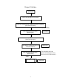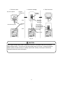
1
COLORMETRY
CMU-124H
Maintenance & Troubleshooting
User’s Manual
MIURA BOILER WEST, INC.
IN OUR CONTINUING EFFORT TO IMPROVE OUR
PRODUCT, INFORMATION IN THIS MANUAL MAY BE
CHANGED WITHOUT NOTICE.
PUBLICATION REVISED SEPTEMBER 2000
Introduction
We appreciate your purchase of the Colormetry system.
This user’s manual covers instructions for the use of your Colormetry system. Please read
through this manual and understand the contents before using the system.
We also recommend that the manual be kept nearby for reference when operating the
Colormetry system.
Operate the system only in accordance with the instructions given in this manual.
We will under no circumstances whatsoever be liable for damages arising from the user's failure
to follow the instructions given in this manual.
(Some details of the instructions contained in this manual may be different from the actual
system purchased. The instructions are also subject to change without prior notice.)
CAUTION
The Colormetry system is a hardness-leakage monitoring system that monitor the harness of
water and issues hardness-leakage alarm. It is not a system that remedies (effects recovery
from) hardness leakage itself.
i
How this manual is organized
This manual consists of ten chapters listed below. We recommend that you familiarize yourself
with the objectives and contents of each, and keep the manual handy for reference.
Organization
Chapter 1
Safety Warnings and Precautions
Explains the danger and precautionary signs and notes that apply to the
handling, installation, wiring and maintenance of the Colormetry system.
.Chapter 2
Maintenance
Explains how to maintain the Colormetry system daily and how to replace the
reagent cartridge, fiber filter cartridge and orifice.
Chapter 3
Troubleshooting
Explains what action should be taken on the occurrence of error, how to clear
alarm and how to verify error records.
Chapter 4
About Displayed Messages
Explains the messages displayed in three modes
ii
Table of contents
Chapter 1
Safety warnings/Precautions........................................................................... 1
Chapter 2
Maintenance ...................................................................................................... 3
2-1
2-2
2-3
Routine care................................................................................................................................ 4
General information .................................................................................................................... 6
Replacing reagent cartridges...................................................................................................... 7
2-3-1
2-4
Chapter 3
3-1
3-2
3-3
3-4
Chapter 4
4-1
4-2
4-3
REPLACING REAGENT CARTRIDGES .................................................................................. 7
Replacing fiber filter cartridge and orifice ................................................................................. 11
Troubleshooting ............................................................................................. 14
About error indications and how to clear alarms ...................................................................... 15
Troubleshooting ........................................................................................................................ 16
Verifying error records (How to use Maintenance mode) ......................................................... 27
How to reset.............................................................................................................................. 31
Digital display descripton .............................................................................. 32
Monitoring Mode ....................................................................................................................... 33
Set Mode................................................................................................................................... 34
Maintenance Mode ................................................................................................................... 34
iii
Chapter 1 Safety Warning/Precautions
Explains the danger and precautionary signs and notes that apply to the handling, installation, wiring and
maintenance of the Colormetry system.
1
This sign indicates a situation in
which incorrect handling might result
in death or injury to the operator, or
that may result in damage to
property.
WARNING
CAUTION
This sign indicates precautions for
the prevention of damage to the
equipment.
NOTE
Instructions for effective operation
and information that may become
useful are explained here.
2
Chapter 2 Maintenance
Explains how to maintain the Colormetry system daily and how to replace the reagent cartridge,
fiber filter cartridge and orifice.
2-1
Routine care...............................................................................................................................................4
2-2
General information....................................................................................................................................6
2-3
Replacing reagent cartridges .....................................................................................................................7
2-4
Replacing fiber filter cartridge and orifice ................................................................................................11
3
(Routine care and replacement of supplies)
2-1 Routine care
(1) Daily inspection items
[1] Verifying the results of monitoring (weekly)
Use an ordinary hardness-indicator reagent to check for evaluation errors due to a possible system
malfunction. Record the results.
An ordinary hardness-indicator reagent may be too low in sensitivity to compare the monitoring of
minute hardness leakage against the Colormetry system. If the monitoring results of the two are
obviously different, the system may have developed a problem.
Note: Use a low-range hardness indicator for this comparison (gpg range is not suitable).
[2]
Verifying the results of automatic monitoring (weekly)
Check for proper automatic monitoring.
Where a remote signal is connected, but does not turn on due to a problem, the system will not enter
the monitor status.
[3]
Checking the state of feed water and drain pipes (as needed)
Check to see if the pipe is free of bends.
Bent pipe will prevent the adequate feeding of water. A bent drain tube will create back pressure,
and in the worst case may cause water leakage.
[4]
Replacing the reagent cartridge (every three to four months)
(Refer to Section 2-3, “Replacing reagent cartridges,” on page 7.)
Replace the cartridge when a “New Cartridge” message appears in the display.
[5]
Replacing the fiber filter cartridge and orifice (as needed)
Refer to Section 2-4, “Replacing the fiber filter cartridge and orifice,” on page 11.)
(2) About verifying the amount of hardness leakage on the occurrence of hardness-leakage alarm (as
needed)
The alarm trigger levels of hardness leakage are as low as 1 mg/L and 2 mg/L for the Colormetry system.
These levels may be too low to be compared against the results of an ordinary hardness-indicator reagent
evaluation method.
To verify the amount of hardness leakage, perform an analysis of water on Ca, Mg, Zn and Cu.
In comparison between the Colormetry system evaluation and water analysis, the results of the two may
differ if the time and location of sample collection are different. For water analysis, obtain a sample from
the Colormetry system's drain, as well, for comparison against the system evaluation result.
4
Recommended periodic maintenance schedule.
No.
(3)
Item
1 week
3~4
months
As Needed
[1]
Verifying the results of monitoring
●
[2]
Verifying the automatic monitor operation
●
[3]
Checking the state of feed-water and drainpipes
[4]
Replacing the reagent cartridge
[5]
Replacing the fiber filter cartridge and orifice
●
[6]
Verifying the level of hardness leakage on
the occurrence of hardness-leakage alarm
●
●
●
About the prevention of freezing
If there is a risk of freezing in an installation in a cold region, but no protection against freezing has been
applied to it, close the main feed-water line valve to the Colormetry system and drain the water at the
supply end. (Drain the filter casing also, and remove and store the fiber filter cartridge in a nonfreezing
area. Freezing may damage the fiber.)
If possible, drain the water from the monitor cell. If it is too difficult to do so, pull the cartridge lever and
remove the reagent cartridge from the main unit.
CAUTION
Freezing may crack the fiber filter cartridge, filter casing or monitor container inside the main unit.
5
2-2 General information
CAUTION
The maximum pressure of raw water to the Colormetry system is 70 psi. Pressure beyond that may
cause water leakage due to deformations in the internal connections or gaskets. Be sure to use it
under the specified pressure.
The drain end must open into the air. Back pressure at the drain end may cause an internal water
leakage.
The main unit has a relief hole in the bottom to quickly drain away internally leaked water and prevent
short circuits.
Do not place any object underneath the installed system that may get wet in the unlikely event of
internal leakage.
Be sure to keep the feed-water and drain-water pipes free of kinks.
WARNING
(1) Do not remove the front cover from the main unit.
(2) Do not disassemble the Colormetry unit.
6
2-3 Replacing reagent cartridges
Replace the cartridges in accordance with the procedure given below so that the system will give a long
service life.
2-3-1 Replacing reagent cartridges
(1) When to replace a cartridge
If a cartridge is used after a “Replace cartridge” [New Cartridge] message is displayed on a self-diagnostic
error, the reagent would either run out or deteriorate to a point where monitoring is no longer possible. If
no spare cartridge is available, obtain and reload one immediately.
If a “Reagent injection confirmation error” [Injection Cfm F] or “Reagent injection error” [Injection F] is
displayed, press the reagent bag with a finger through the hole in the back of the cartridge to check for the
remaining reagent. If none is felt in the bag, replace the cartridge immediately.
(2) How to replace a cartridge
CAUTION
• Replace the cartridge with the power left on but only while the system is in monitor standby mode.
• Never remove the check tube attached to the nozzle of the reagent cartridge (refer to Section 2-2-2,
“External appearance of reagent cartridge,” on page 7 in the Colormetry General Information
Manual.) Keep the fingers off the check tube too, since doing so may affect the amount of injection.
• When installing a new cartridge, push it down slowly, being careful not to let the nozzle and check
tube hit of the main unit.
7
Reagent Cartridge
Begin
replacement.
Pull out the cartridge lever to unlock it.
Lift up the cartridge with both hands and remove it completely.
(The buzzer will sound.)
(Sample display)
Push the Manual Monitor switch.
(Buzzer stops.)
Cartridge off
Install a new cartridge into Colormetry main unit.
(Buzzer sounds again.)
Push back the cartridge locking lever
and lock it positively.
Push the Manual Monitor switch.
(Buzzer stops.)
SW on Cfm
(Turn the switch within one
minute after the buzzer sounds.)
(Refer to the CAUTION remarks.)
Status
Self-check mode
8
Self-Check
1. Pull out the lever
Top view of system
2. Insert the cartridge
Reagent
cartridge slot
Reagent
cartridge
Bottom of
horizontal
design line
Tube
Front view of system
3. Push in the lever
Cartridge
lever
The bottom of
horizontal design
line approximately
lines up with the
cover edge
Tube
Edge of cover
Fig. 15
CAUTION
If the reagent cartridge being used is temporarily removed for reinstallation later, do not press the
Manual Monitor switch. The buzzer will stop automatically within one minute. Pressing the Manual
Monitor switch will reset the timer for cartridge replacement, thereby rendering the automatically
displayed replacement date meaningless.
9
CAUTION
About the reagent cartridge
[1] The reagent cartridge has a definite life. Finish a cartridge within one year of its date of
manufacture, that is stated on the cartridge box. (A cartridge is used up in about four
months.)
[2] Do not store cartridges for a long period of time. If they are to be stored, select a cool, dark
place.
[3] Do not break the seal on the reagent cartridge bag until the moment of installation. Doing so
will accelerate its deterioration.
[4] Do not touch the nozzle or tube of the reagent cartridge. Doing so will affect the injection
level, and in the worst case may stop monitoring.
[5] Do not use the reagent cartridge for other than the Colormetry system.
[6] Never disassemble a reagent cartridge. Reagent may splatter onto the skin or in the eyes.
[7] Dispose of the reagent cartridge, assembled intact, as plastic waste.
[8] If the reagent gets on the skin or in the eyes, immediately rinse it off with water.
10
2-4 Replacing fiber filter cartridge and orifice
(1) When to replace
If the water flow is small even though the supply pressure is within the specified range, the fiber filter or
orifice is clogged or has deteriorated. Specifically, when one of the following alarms is issued in the selfdiagnostic error mode, the clogging or deterioration of the filter or valve should be suspected, if nothing
else:
[1] “Wash error” [Wash F]
[2] “Reagent injection error” [Injection F]
[3] “Wash water flow insufficient” [Wash Flow F]
The lifespan of the fiber filter should be about a year on city water, but may be shorter depending on the
water quality and supply pressure. Even if none of the above alarms is issued, it should be replaced after
a year as a rule of thumb.
When replacing the fiber filter, also install the new orifice that comes with the replacement filter.
(2) How to replace
CAUTION
Water spills around the main unit when replacing the fiber filter. Do not leave things underneath the unit
that should not get wet.
CAUTION
There is an orifice fit on the end of the filter casing. If the orifice is not found on the filter casing when it is
removed from the main unit, the valve may have been left behind in the filter mount of the main unit.
Remove the orifice without scratching the mount.
11
Filter Cartridge
Begin the replacement.
Shut the main feed-water line valve.
Push the Manual Monitor switch.
(Wait 15 seconds)
Pull out the power plug.
Detach the feed-water tube from the quick-disconnect
coupling at bottom of filter-casing assembly.
Remove the filter-casing assembly.
Untwist the top and bottom halves of filter casing. Remove the fiber
filter cartridge.
Insert a new filter cartridge into the top half of filter
casing, then firmly screw the bottom half.
Install the new orifice that comes with the new filter
cartridge.
Screw the filter-casing assembly into the main unit.
(No need to screw in hard.)
Insert the feed-water tube into the quick-disconnect
coupling at the bottom of the filter-casing assembly.
Open the main feed-water line valve.
Check for leakage. Connect the power plug.
Self-check mode
12
Self-Check
Detach the filter-casing
assembly from the main unit.
Replace the old orifice with the new
one furnished with the new fiber filter.
Detach the 1/4” (6 mm) dia. feed-water
tube from the quick-disconnect
li
Untwist the top and bottom halves of the filter
casing and remove the fiber filter cartridge.
Install the new filter cartridge in the top
half of the filter casing. Firmly screw
the bottom half into the top half.
Screw the filter-casing
assembly back into the main
unit. (There is no need to
screw it in very tightly.)
Insert the 1/4” (6 mm) dia.
feed-water pipe into the
quick-disconnect coupling.
13
Chapter 3 Troubleshooting
Explains what action should be taken on the occurrence of error, how to clear alarm and how to verify error
records.
3-1
About error indications and how to clear alarms......................................................................................15
3-2
Troubleshooting .......................................................................................................................................16
3-3
Verifying error records (How to use Maintenance mode) ........................................................................27
3-4
How to reset .............................................................................................................................................31
14
3-1 About error indications and how to clear alarms
On the occurrence of an error, a typical example of a possible cause of the error is indicated in the LCD
display. Refer to the “Troubleshooting” flowchart for other causes.
If an error could not be recovered, contact your dealer immediately.
Error indications on an alarm (common to all errors in the self-check error mode)
When an error occurs, the system sounds a buzzer and the external alarm’s master output contact closes.
The LCD display will alternately indicate the error description and most recent result of evaluation (or,
“****:- - - -,“ if no evaluation is being made). (Note: Only the error description will be indicated in case of a
DIP switch setting error.)
Buzzer sounds.
External contact closes.
Push the manual
monitor switch.
(Buzzer stops)
The display indicates the
error description and result of
evaluation, alternatively.
How to clear alarm
• With the buzzer sounding, press the Buzzer Reset (Manual Monitor) switch to stop it. Pressing the
switch will not start the Manual-monitoring mode. Pressing the switch once again will start the Selfcheck or Monitor mode. The external alarm's master contact will not be reset until the condition is
evaluated as normal again.
• If the conditions for monitoring are satisfied, monitoring will start even if an alarm is on. Alarm will
automatically be cleared if the cause for system error has solved. However, if the error is due to
unattachment of the cartridge, monitoring (self-check mode) will not start until attachment of the
cartridge is confirmed. Monitoring will not start either on a DIP switch setting error, until the correct
settings are made and system is restarted.
Note: The Buzzer Reset switch also functions as the Manual Monitor switch.
15
3-2
Troubleshooting
Cartridge Error
Message indicated in display:
“Cartridge is out” [Cartridge Off] (within 10 minutes of error occurrence);
or
“Cartridge out error” [Cartridge Off F] (after 10 minutes of error occurrence)
Note: The first LCD message will
change to the second
message after 10 minutes of
error occurrence. The buzzer
sounds during the first 10
minutes, and the external
alarm contact closes only after
10 minutes.
Try reinstalling the reagent
cartridge and locking it with
the cartridge lever.
NO
Is the reagent cartridge within
one year of the manufactured
date shown on its case ?
YES
Replace the old
cartridge.
Push the Manual
Monitor switch .
Note: Refer to the “Caution”
remarks on page 9.
YES
Is error cleared?
Causes :
The reagent cartridge is
not fully inserted.
Action:
Reinsert the cartridge.
(See to page 7.)
NO
Remove the reagent cartridge.
Is the shield plate or
rib broken off?
NO
Call your nearest MIURA
Representative
16
YES
Causes :
• Cracked under stress
• Cracked during
shipment
Action:
Replace the cartridge.
Internal Pump Error
Message indicated in display:
“Pump confirmation error” [Pump Cfm F] (occurs during verification
of the pump in its home position in the self-check mode);
or
“Pump error” [Pump F] (occurs during reagent injection in the
normal monitor mode)
Cause: Due to a failure to verify the
pump being in its home
position.
Note: A Colormetry system with an
error cannot be repaired at the
site. Process the system as a
field claim.
Press the reagent cartridge
into the main unit.
Press the Manual Monitor
switch to start monitoring.
Wait for a while.
Does the error recur?
NO
Causes:
The cartridge is not properly inserted.
Foreign matter is stuck inside.
The cartridge tube is obstructed.
YES
• Action:
After monitoring, check for
foreign matter, the tube
dislodged from the cartridge or
reagent leakage.
Call your nearest MIURA Representative.
17
Wash Error
Message indicated in display:
“Wash confirmation error” [Wash Cfm F] (occurs during
verification of wash in the self-check mode);
or
“Wash error” [Wash F] (occurs during verification of
wash in the normal monitor mode).
Is the sample taken
downstream of the feedwater control valve (such
as the motor valve)?
YES
Is monitoring performed as
soon as the feed-water
control valve opens? (Is the
remote signal connected?)
NO
NO
Is water draining from the
system during monitoring?
Causes :
1 Insufficient water flow,
2 Bubbles in the monitor container
3 Foreign matter mixed in with the water.
NO
• Action:
Connect the remote signal
to delay monitoring during
water stoppage.
Select a remote-signal
delay time. (See page 17
in the General Information
Manual.)
YES
YES
Is the remote signal set up
and wired appropriately?
Cause :
Insufficient pressure while
waiting for water to feed
through the softener.
NO
(To *1, next page)
YES
Change the setting. (See page 26 in
the Installation and Start-Up Manual.)
Try monitoring several times with
the orifice at the end of filter casing
removed.
Change the wiring. (See page 11 in
the Installation and Start-Up Manual.)
Does the error occur again?
Cause: Air is mixed in inside filter casing or supply line.
NO
• Action:
Repeat the monitoring several times to
eliminate any air. (Replace a clogged or
deformed orifice.) (See page 11.) Run
again to verify error-free monitoring.
YES
Reinstall the orifice.
Take Colormetry system off the wall.
Remove the reagent cartridge from the main unit.
(To *2, next page)
18
(From *2, previous page)
Conform to the specified range
Ambient temperature:
41~122°F (5~50°C)
Water temperature:
41~104°F (5~40°C)
(From *1, previous page)
NO
Are the ambient and
water temperatures
appropriate?
Turn the Colormetry unit up,
side down, and dump out
any loose objects.
Be aware of water pouring
out.
Catch the sample water and
stirrer in a beaker, etc.
YES
Maintain supply pressure in
range, 7.1 psi~71 psi.
NO
Is the supply
pressure
maintained?
YES
Remove foreign object.
Remove the filter-casing
assembly from the main unit
and check it. (See page 11.)
YES
Is there a foreign object
in the filter casing’s
connection area?
NO
Is foreign object mixed
into the water?
Are there multiple or
no stirrers inside?
NO
YES
Clear the kinked or clogged line.
Is the feed-water
or drain-line
kinked or
clogged?
NO
Replace the fiber filter and
orifice. (Refer to page 11.)
YES
Is the fiber filter
clogged?
NO
Replace the orifice.
(Refer to page 11.)
YES
Is the orifice clogged
or excessively
deformed?
NO
Call your nearest MIURA
Representative.
19
YES
Remove any foreign matter.
Leave or add only one stirrer in the
monitor container (tubular hole).
Return the Colormetry unit to its
location, perform monitoring and
verify that no error occurs.
Insufficient Wash Flow Error
Message indicated in the display:
“Insufficient wash flow” [Wash Flow F]
Is the sample taken
downstream of the feedwater control valve (such
as the motor valve)?
YES
Is monitoring performed as NO
soon as the feed-water
control valve opens? (Is the
remote signal connected?)
YES
NO
NO
Is the flow of drainage from
Colormetry (drain tube) 300
cc/min. or greater during
monitoring (wash cycle)?
Cause : The alarm is a low drain flow
that is less than 250 cc/min.,
continuously repeated three times.
YES
Is the remote signal
set up and wired
appropriately?
NO
YES
Remove Colormetry from
the wall.
Cause:
Insufficient pressure while
waiting for water to feed
through the softener.
• Action:
Connect the remote
signal to delay
monitoring during
water stoppage.
Select a remotesignal delay time.
(See page 17 in the
General Information
Manual.)
Change the setting. (Refer to page 26 I
the Installation and Start-Up Manual.)
Change the wiring. (Refer to page 11 in
the Installation and Start-Up Manual.)
Remove the reagent cartridge from
the main unit.
(Continued to *4, next page)
20
(From *4, previous page)
(From *3, previous page)
Conform to the specified range
Ambient temperature:
41~122°F (5~50°C)
Water temperature:
41~104°F (5~40°C)
NO
Are the ambient and
water temperatures
appropriate?
Turn the Colormetry unit up
side down, and dump out
any loose objects.
Be aware of water pouring
out.
Catch the sample water and
stirrer in a beaker, etc.
YES
Maintain supply pressure in
range, 7.1 psi~71 psi.
NO
Is the primary
supply pressure
maintained?
YES
Replace the fiber filter and
orifice. (Refer to page 11.)
YES
Is the fiber filter
clogged?
NO
NO
Is foreign object mixed
into the water?
Are there multiple or
no stirrers inside?
YES
Replace the orifice.
(Refer to page 11.)
YES
Is the orifice clogged
or excessively
deformed?
NO
Remove the foreign object.
Remove the filter-casing
assembly from the main unit
and check it. (Refer to page
11.)
Clear the kinked or clogged
line.
YES
Is there foreign
object in the filter
casing receptacle?
NO
YES
Is the water feedwater or drainwater line kinked
or clogged?
NO
Call your nearest MIURA
Representative
21
• Action:
Remove any foreign matter.
Leave or add only one stirrer
in the monitor container
(tubular hole).
Return the Colormetry unit to
its location, perform
monitoring and verify that no
error occurs.
Reagent Injection Error
Message indicated in the display:
“Reagent injection confirmation error” [Injection Cfm F]
(occurs during verification of wash in the self-check mode);
or
“Reagent injection error” [Injection F] (occurs during
verification of wash in the normal monitor mode)
Is reagent available
in the reagent
cartridge?
Causes:
• There is insufficient water flow.
• The amount of reagent injection is
off the specified range.
• Stirring is not effected properly.
NO
Replace the reagent cartridge.
(Refer to page 7.)
YES
Is the reagent within
one year of its
manufactured date?
NO
Replace the reagent cartridge.
(Refer to page 7.)
YES
Is the sample taken
downstream of the feedwater control valve (such
as the motor valve)?
YES
Is monitoring taken as soon NO
as the feed-water control
valve opens? (Is the
remote signal connected?)
NO
(To *5, next page)
(To *6, next page)
YES
Is the remote
signal set up and
wired
appropriately?
NO
YES
Are the ambient
and water
temperatures
appropriate?
NO
YES
NO
Remove Colormetry unit
from wall.
Remove the reagent cartridge
from the main unit.
(To *7, next page)
22
Change setting.
(See page 26 in the
Installation and StartUp Manual.)
Change wiring. (See
page 11 in the
Installation and Start-Up
Manual.)
YES
YES
Is drainage water colored with
Reagent sample ?
(Check carefully for color change
within 3 minutes after pushing
manual monitor button)
• Action:
Connect the remote signal
to delay monitoring during
water stoppage.
Select a remote-signal delay
time. (See page 18 in the
General Information
Manual..)
YES
NO
Is water draining from
the Colormetry system
during monitoring ?
Cause:
Insufficient pressure while
waiting for water to feed
through the softener.
Conform to the specified
range
Ambient temperature:
41~122°F (5~50°C)
Water temperature:
41~104°F (5~40°C)
(From *7, previous page)
Conform to the specified range
(From *5, previous page)
Ambient temperature:
41~122°F (5~50°C)
Water temperature:
41~104°F (5~40°C)
NO
Are the ambient and
water temperatures
appropriate?
Turn the Colormetry unit up
side down, and dump out
any loose objects.
Be aware of water pouring
out.
Catch the sample water and
stirrer in a beaker, etc.
YES
Maintain supply pressure in
range, 7.1 psi~71 psi.
NO
Is the primary
supply pressure
maintained?
YES
Remove foreign object.
Remove the filter-casing
assembly from the main unit and
check it. (Refer to page 11.)
YES
Is there a foreign object
in the filter casing’s
connection area?
YES
NO
Is foreign object mixed
into the water?
Are there multiple or
no stirrers inside?
NO
Clear the kinked or clogged
line.
YES
Is the supply or
drain line kinked
or clogged?
Causes :
Foreign object is mixed in.
Multiple stirrers cannot stir effectively.
NO
Replace the fiber filter and
orifice. (Refer to page 11.)
YES
• Action:
Remove any foreign matter.
Leave or add only one stirrer in
the monitor container (tubular hole).
Return the Colormetry unit to its
location, perform monitoring and verify
that no error occurs.
Is the fiber filter
clogged?
NO
Replace the reagent cartridge.
Replace the orifice.
(Refer to page 11.)
YES
Is the orifice clogged
or excessively
deformed?
NO
Call your nearest MIURA
Representative
Perform monitoring
YES
Does the error
recur?
NO
Cause:
Problem in reagent
cartridge.
23
(From *6,
previous page)
Constant Hardness Alarms
The hardness leakage alarm is issued
very often,
or
Non-hardness leakage is evaluated as
harness leakage.
Is the reagent within
one year of its
manufacture date?
NO
Replace the reagent cartridge. (See
page 7.)
YES
Change the setting.
(See page 26 in the
Installation and StartUp Manual.)
Change the wiring.
(See page 11 in the
Installation and StartUp Manual.)
Cause:
Ions dissolved from
plumbing after shutting
off the water softener
for a long period of
time.
Is the monitoring performed
as soon as the feed-water
control valve opens?
(Is the remote signal
connected?)
NO
Stagnant water in
the plumbing might
be being monitored
as a sample.
YES
NO
Is the remote signal
set up and wired
appropriately?
YES
YES
Does hardness leakage
frequently occur after
leaving the water
softener off for a long
period (one night)?
• Action:
Increase the settings of
abnormal condition
retry, abnormalNO
monitoring retry and
response (alarm) cycle
Use the hardness-indication
to prevent the
method to verify monitoring
occurrence of alarm on
when Colormetry indicates
a temporary hardness
hardness leakage.
leakage (due to the
water softener
characteristics or
dissolved ions from the
plumbing etc.).
Do both the
Note: Water hardness
Colormetry and
must still be controlled
hardness indicator
carefully, since the scale
results coincide?
material is dissolving
YES
out.
NO
Malfunctioning softener valve
is causing hardness leakage.
Cause:
Stagnant water in the
plumbing is being
sampled while the
water softener is shut
off.
Perform monitoring
several times after
purging stagnant water
by feeding water through.
NOHarness leakage
occurs ?
• Action:
Obtain remote signal
from communications
equipment.
If no remote signal is
available, provide one
by adding a flow switch
or the like to inhibit
monitoring during
water stoppage.
YES
Use the hardnessindication method to
verify hardness leakage
Hardness leakage YES
is caused by a
malfunctioning
water softener.
Is hardness
leakage actually
occurring?
NO
Remove Colormetry
from the wall.
(To *8, next page)
• Action:
Allow the water softener
to regenerate.
24
(From *8, previous page)
Remove the reagent cartridge
from the main unit.
Turn the Colormetry unit up side down,
and dump out any loose objects.
Be aware of water pouring out.
* Catch the sample water and stirrer in a
beaker, etc.
Does a stirrer or multiples stirrers fall out?
Is foreign matter mixed into the water?
YES
NO
Remove any foreign matter.
Leave only one stirrer in the monitor
container (tubular hole).
Return the Colormetry unit to its
location, perform monitoring and verify
that no error occurs.
Return the stirrer to the monitor
container (tubular hole).
Return the Colormetry unit to its
location and perform monitoring.
Causes :
Trace hardness
leakage due to watersoftener problems.
Excessive amount of
metal ion dissolution
from the plumbing and
elsewhere.
• Action:
Allow the water softener to
regenerate.
Check out the plumbing for
corrosion.
Avoid the use of material that
is prone to dissolution of
metallic ions (such as white
gas plumbing).
Collect drain water from the
Colormetry system and perform a
water analysis (such as on Ca,
Mg, Zn and Cu).
YES
Are the results of
analysis normal?
Note: Metal ions, Zn, Cu, etc., react the same
way as the hardness indication method.
• Results of evaluation of zinc ions by
Colormetry
Unit: mg/L
Zn concentration
0.5
1.0
2.0
Total hardness 0
1
1.5
3
Total hardness 1
2
2.5
5
• Results of evaluation of copper ions by
Colormetry
NO
Call nearest MIURA
Representative.
Total hardness 0
Total hardness 1
Unit: mg/L
Cu concentration
0.5
1.0
2.0
0.75
1.8
5
2
3.3
5
• Results of evaluation of iron-ion
concentration by Colormetry
Colormetry monitoring is not especially
affected by iron.
25
DIP Switch Error
DIP switch error
Are the DIP switches
correctly set?
YES
NO
Set the DIP switches correctly.
Refer to page 21 in the Installation
and Start-Up Manual.
Push the Reset switch.
Is the alarm cleared
now?
(Has the self-check
finished as normal?)
YES
NO
Call your nearest MIURA Representative.
26
Cause :
DIP switch setting error
3-3 Verifying error records (How to use Maintenance mode)
Historical records of hardness leakage and system errors may be checked in Maintenance mode.
Additionally, input and output status and other abnormalities may also be displayed in Maintenance mode,
but they are not required during on-site repairs.
Normally useful items in the records are listed below.
Starting and exiting from Maintenance mode
Each depression of the display indicator switch changes modes as follows:
Monitoring mode → Setting mode → Maintenance mode
• Starting Maintenance mode: Press the display indicator switch as required to start Maintenance mode.
• Exiting from Maintenance mode: Press the indicator to exit from Maintenance mode.
If no switch is operated for 10 minutes, however, the mode changes to Monitoring mode automatically.
Items displayed in Maintenance mode
In the table shown below, the items under category 1 are selected by the Item switch, and those under
category 2 by the Up switch.
27
M Result hardness
LCD display
(an example)
MHardness 2.0 mg/L
(Note 1)
M CPU version
MCPUver DE111012
***…CPU version
M Date(m/d/y) & time
M06/23/98 15:28
Type of monitoring
Mhardness Mon
M Input-output mode
MIN-OUT Mode *
(Note 2)
M Output1
MOUT1 1111 1111
0000 0000-1111 1111
M Output2
MOUT2 1111 1111
0000 0000-1111 1111
M Input1
MIN1 1111 1111
0000 0000-1111 1111
M Input1
MIN2 1111 1111
0000 0000-1111 1111
M AD FF FF FF
MAD FF FF FF
00 00 00-FF FF FF
M AD Thermista: FF
MAD (Thmsta): FF
00-FF
M AD(R): FF FF
MAD(R): FF FF
00 00-FF FF
M AD(-): 00 00
MAD(O): 00 00
M AD(G): FF FF
MAD(G): FF FF
M Pre Wash period 9.99
second
M Set M-alkalinity
MWash Pd 9.99S
MMAlkal<60mg/L
Under 60/300 and up
M select from LED
wavelength table
M Operation status
MWL:L
S/L
MOp Stus: FF
00-FF
Category 1
Category 2
M Alarm description
00 00-FF FF
MAlarm Content *
M Error table 1
MError1: 11111111
00000000-11111111
M Error table 2
MError2: 11111111
00000000-11111111
M Cartridge data
(Note 3)
Range of indicated values
MCartridge Dta *
M Cartridge replacement
date(m/d/y)
M Cartridge used hours
since replacement
M Reagent injection
frequency since cartridge
replacement
MC Exc 06/23/98
MC Hrs 999999
00000-999999 (hours)
MRgt Inj Fqc 9999
0000-9999 (times)
28
Category 1
M Hardness leakage
record 1
(Note 4)
M Hardness leakage
record 2
M Hardness leakage
record 3
M System error record
1
(Note 5)
M System error record
2
M System error record
3
M black out record 1
(Note 6)
Category 2
LCD display
(an example)
MLeakage Log 1
Range of indicated values
M Date of Hardness
leakage(m/d/y)
M Time of Hardness
leakage
M Evaluation standard at
concentration
M AD(R): FF FF
MDate 06/23/98
MEvl Std Conc: 2
0-2
MAD(R): FF FF
00 00-FF FF
M AD( ): 00 00
MAD(-): 00 00
M AD(G): FF FF
M AD(G): FF FF
00 00-FF FF
M Total leakage minute
MLeakage Min9999
0000-9999 (minutes)
M Date of reset(m/d/y)
MRset 06/23/98
M Time of reset
MRset Time 15:28
MTime 15:28
(Same as “M Hardness leakage record 1”)
(Same as “M Hardness leakage record 1”)
MStm Fault Log 2
M Date of System
error(m/d/y)
M Time of System error
MDate 06/23/98
MTime 15:28
M Error table 1
MError1: 11111111
00000000-11111111
M Error table 2
MError2: 11111111
00000000-11111111
M Date of reset(m/d/y)
MRset 06/23/98
M Time of reset
MRset Time 15:28
(Same as M system error record 1)
(Same as M system error record 1)
MBlk Out Log 1 *
M Date of black out(m/d/y)
MDate 06/23/98
M Time of black out
MTime 15:28
M Date of reset(m/d/y)
MRset 06/23/98
M Time of reset
MRset Time 15:28
M black out record 2
(Same as “M System error record 1”)
M black out record 3
(Same as “M System error record 1”)
29
Note 1:
If the results of monitoring are in the 0—1mg/L, 1—2 mg/L , 2—5 mg/L, and 5 mg/L and up, the
indicated values will be 0.0 mg/L, 1.0 mg/L, and 2.0 mg/L, and 5.0 mg/L, respectively. If the result is
abnormal, the indicated value will be 9.9 mg/L.
Note 2:
If a “>” symbol is indicated in the LCD display, it means there is an item to be selected by Up switch.
Normally, the procedure is not utilized except in case of “M Set M-alkalinity.”
Note 3:
The category indicates the date of cartridge installation, cumulative hours used and number of times
used (number of times the injection pump has operated) since the date of installation.
When the number of hours or times used has reached 3,500 hours or times, a message to replace the
reagent cartridge is displayed.
Note 4:
The historical data for up to three most recent occurrences of hardness leakage is stored.
The cumulative operating time of hardness leakage, [M Total leakage minutes], counts time only if the
remote signal function is set for “Monitoring in remote signal-on state.”
Note 5:
The historical data for up to three most recent system errors is stored in this category.
The error table for the category describes previously occurred system errors.
The LCD indications of the error table in this category also corresponds to the table referred to in Note
5.
The LCD display will indicate [1] for the description of an error, as is the case with Note 6.
<Error table>
Error code
(1)
B7
Replace
reagent
B6
Reagentinjection
error
Error code
(2)
Abnormal
***
concentration
B5
Reagent
injectionpump error
B4
Lightreceptor
error
B3
B2
Wash error Reagentinjection
error (K)
B1
B0
Wash error Reagent
(K)
injectionpump error
(K)
Decreased DIP switch Cartridge
sample
setting
out
flow
error
***
***
***
Note: The notation (K) shows an error that has occurred in the self-check mode only.
Note 6:
The historical data will be stored on up to three most recent power outage.
The error code describes an error currently occurring in the system. An error and a normal state are indicated
by a [1] and [0], respectively.
[Example] In case of a reagent-injection error
Displays: M Table 1 = 0100 0000
30
3-4 How to reset
Ordinarily, no resetting action is required.
(1) Normal reset
All setting data and historical data are preserved when a reset is executed.
[1] How to execute a reset
Detach the front cover from the front side of the main unit, then press the Reset switch.
[2] How system operates when the Reset switch is pressed
Refer to Section 3-2-1, “(1) If the data-memory backup battery has been charged by the time the
power is turned on . . . , or when reinitialized from a reset,” on page 23 of the Installation and Start-Up
Manual.
(2) All reset
When an all reset is executed, all setting data and historical record data will be initialized.
[1] How to execute an All Reset
a. Detach the front cover on the front of the main unit, and turn DIP switch DSW-8 to “On.”
b. With DSW-8 turned to “On,” press the Reset switch.
c. Check the display to verify that an “All clear” message is indicated following a “CPU version”
message. When the “All clear” message disappears, return the DSW-8 to “Off.”
[2] About the system after reset is executed
Refer to Section 3-2-1, “(2) If the data-memory backup battery has not been charged when the power
is turned on, or when reinitialized after executing an All Reset, on page 23 of the Installation and StartUp Manual.
31
Chapter 4 Digital display description
Explains the messages displayed in three modes.
4-1
Monitoring Mode ........................................................................................... 33
4-2
Set Mode....................................................................................................... 34
4-3
Maintenance Mode ....................................................................................... 34
32
4-1 Monitoring Mode
1
2
3
4
5
6
7
8
9
10
11
12
13
14
15
16
17
18
19
20
21
22
23
24
25
26
27
28
29
Display
CPUverDE111012
Hardness Monitor
Pump Start Cfm
Self Check
Self Check Retry
Std-by: ---Std-by: 0-1mg/L
Std-by: 1-2mg/L
Std-by: >2mg/L
Monitor On
Monitor On Retry
Result: 0-1mg/L
Std-by: 0-1mg/L
Result: 1-2mg/L
Std-by: 1-2mg/L
Result: >2mg/L
Std-by: >2mg/L
Warning: >1mg/L
Warning: >2mg/L
Cartridge OFF
Cartridge OFF F
Pump Cfm F
Pump F
Wash F
Wash Cfm F
Injection Cfm F
Injection F
Wash Flow F
Photo Rpt F
SW ON Cfm
Dip SW Err
New Cartridge
Description
CPU version
Hardness monitor
During verification of the pump in its home position
Self check
Self check retry
Waiting foe monitoring stage
Monitor stand-by: 1mg/L or less
Monitor stand-by: Between 1mg/L and 2mg/L
Monitor stand-by: 2mg/L or more
Monitoring ionic concentration(hardness)
Monitor on retry
Result: 1mg/L or less
Monitor stand-by: 1mg/L or less
Result: Between 1mg/L and 2mg/L
Monitor stand-by: Between 1mg/L and 2mg/L
Result: 2mg/L or more
Monitor stand-by: 2mg/L or more
Hardness leakage detected: 1mg/L or more
Hardness leakage detected: 2mg/L or more
Cartridge disconnected
Cartridge disconnected fault
Pump confirmation error
Reagent injection pump fault
Insufficient pre-wash
Faulty confirmation on pre-wash
Faulty confirmation on reagent injection
Incomplete reagent injection
Insufficient water flow for wash
Photoreceptor fault
Switch ON confirmed after cartridge replacement
Dip switch error
Need cartridge replacement
33
4-2 Set Mode
1
2
3
4
5
6
7
8
9
10
11
12
Display
SDate 06/23/98
STime 15:28
SIntvl 060min
SStart 08:30
SStop 20:30
SRet Sgl Off
SRet Sgl On
SRet Sgl Dl 10s
SAlarm Set2.0mg/L
SAlarm Inc No:2
SAlarm Inc No:3
SAlarm Det No:3
SC Rpl 06/23/98
Description
S Date (m/d/y) 06/23/98
S Time 15:28
S Monitor interval 60 min
S Start time 08:30
S Finish time 20:30
S Monitor by remote signal off
S Monitor by remote signal on
S Remote signal time delay
S Alarm set at 2mg/L
S 2 consecutive incidents set alarm off
S 3 consecutive incidents set alarm off
S 2nd leakage detection set alarm off
S Cartridge replacement date(m/d/y)
S: Indicate Set Mode
4-3 Maintenance Mode
1
2
3
4
5
6
7
8
9
10
11
12
13
Display
MHardness 2.0mg/L
MCPUver DE111012
M06/23/98 15:28
MHardness Mon
MIN-OUT Mode *
MOUT1 1111 1111
MOUT2 1111 1111
MIN1 1111 1111
MIN2 1111 1111
MAD FF FF FF
MAD (Thmsta): FF
MAD(R): FF FF
MAD(-): 00 00
Description
M Result hardness 2.0mg/L
M CPU version
M Date(m/d/y) & time
M Hardness monitor
M Input-output mode
M Output1 1111 1111
M Output2 1111 1111
M Input1 1111 1111
M Input2 1111 1111
M AD FF FF FF
M AD Thermista: FF FF
M AD(R): FF FF
M AD(-): 00 00
34
14
15
16
18
19
20
21
22
23
24
25
MAD(G): FF FF
MWash Pd 9.99S
MMAlkal < 60mg/L
MMAlkal < 120mg/L
MMAlkal < 300mg/L
MMAlkal <500mg/L
MWL: L
MWL: S
MOp Stus: FF
MAlarm Content *
MError1: 11111111
Merror2: 11111111
MCartridge Dta *
MC Exc 06/23/98
MC Hrs 999999
MRgt Inj Fqc9999
26
27
28
29
30
31
32
33
34
MLeakage Log1 *
MDate 06/23/98
MTime 15:28
MEvl Stg Conc: 2
MLeakage Min9999
MRset 06/23/98
MRset Time 15:28
MStm Fault Log1*
MBlk Out Log1 *
17
M AD(G): FF FF
M Pre Wash period 9.99 secoud
M Set M-alkalinity at 60mg/L or less
M Set M-alkalinity at 60mg/L to 120mg/L
M Set M-alkalinity at 120mg/L to 300mg/L
M Set M-alkalinity at 300mg/L to 500mg/L
M select from LED wavelength table: L
M select from LED wavelength table: S
M Operation status: FF
M Alarm description
M Error table 1: 11111111
M Error table 2: 11111111
M Cartridge data
M Cartridge replacement data(m/d/y)
M Cartridge used hours since replacement: 999999
M Reagent injection frequency since cartridge replacement:
9999
M Hardness leakage record 1
M Date of Hardness leakage(m/d/y) 06/23/98
M Time of Hardness leakage 15:28
M Evaluation standard at concentration of 2
M Total leakage minute: 9999min.
M Date of reset (m/d/y): 06/23/98
M Time of reset: 15:28
M System error record 1
M black out record 1
M: Indicate Maintenance Mode
Maintenance Mode display can be changed by pressing the “Items” switch.
In the event an * mark appears, mode/display can be changed by pressing the “UP” switch.
35