1
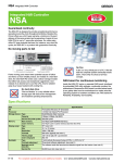
Ver.1.01
MELSEC-Q Series
CONTECWinCPU module
This product is the controller which can be installed with
Mitsubishi General programmable controller CPU, MELSEC-Q
Series and supports Windows OS.
This product can work as the multiple CPU configuration with
programmable controller CPU and it realizes the seam less
processing of both controlling and computing. It can boot from
a built-in SSD and a CF card in a CF card slot (Type I).
This product has two LAN ports. They realize the open systems
for Web, Internet and Intranet.
Embedded-type CPU and chipset have been adopted. The use
of readily available parts ensures the ease of the use of the
product. In addition, the use of self-customized BIOS allows
support to be provided at the BIOS level.
Model
CPU
PPC-100-DC5511
PPC-100-DC5311
PPC-100-DC551A
PPC-100-DC531A
Intel Atom
N450
1.66GHz /
1GB
DDR2
SDRAM
Storage
OS
4GB SSD
Windows Embedded
Standard 2009
Japanese
4GB
CF card
4GB SSD
4GB
CF card
Windows Embedded
Standard 2009
English
Intel, Intel Atom, Intel Core and Celeron are registered trademarks of
Intel Corporation. Microsoft and Windows are trademarks of Microsoft
Corporation. MELSEC, CC-Link are trademarks of Mitsubishi Electric
Corporation. Other brand and product names are trademarks of their
respective holder.
* Specifications, color and design of the products are subject to
change without notice.
* Please contact us for using OS in English or other languages.
https://www.contec.com/contact/
Features
Option List
MELSEC-Q Series programmable controller CPU modules
cover sequence controlling. This CONTECWinCPU module
covers computing. The combination of them realizes the
seam-less processing of information and control data.
CF Card
CF-1GB-B
CF-2GB-B
CF-4GB-B
CF-8GB-B
Very small Windows OS system (2-slot size of a
MELSEC-Q series programmable controller CPU)
TFT color liquid-crystal display
Adopt Intel® Atom™ processor N450, belonging to energy
saving platform. It manages both enough performance and
energy saving.
FPD-H21XT-AC
Various interfaces are installed as the standard.
1000BASE-T LAN, USB2.0, CF card slot and so on.
FPD-M21VT-AC
The use of a Contec-customized BIOS (mfd. By
Phoenix-Award) allows the support provided at the BIOS
level.
1GB CompactFlash for Fix Disk
2GB CompactFlash for Fix Disk
4GB CompactFlash for Fix Disk
8GB CompactFlash for Fix Disk
<Analog RGB types>
FPD-L21ST-AC
(15 inch 1024 x 768 dots,
Panel mounted type)
(12.1 inch 800 x 600 dots,
Panel mounted type)
(10.4 inch 640 x 480 dots,
Panel mounted type)
Touch-panel cable for an analog RGB display
IPC-CBL3-2
AT host Touch panel, COM cable (2m)
IPC-CBL3-5
AT host Touch panel, COM cable (5m)
P A CF card can be installed as an external recording
media. The use of it is preferable if it works where shock
and vibration are exist and works for a continuous long
time.
Built-in SSD has double write protect functions (an EWF
function of OS and write procect function of DIP switch). It
realizes more reliable protection for important data.
Supported OS
・Windows Embedded Standard 2009
PPC-100
1
Ver.1.01
Specifications
Item
Installation Environment
Intel® Atom™ Processor N450 1.66GHz
Chipset
Intel® ICH8M
Memory L1 Cache
Instruction 32KB + Data 24KB
Video
Item
Content
CPU
Condition
Surrounding air temperature
0 - 55°C
Surrounding storage
temperature
-25 - 75°C
5 - 95%RH (No condensation)
L2 Cache
512KB
Surrouding operating
humidity
Main
memory
1GB (3.3V 200-pin DDR2 SO-DIMM DDR667Socket x 1)
Surrouding storage humidity
5 - 95%RH (No condensation)
Vibration resistance
Controller
N450 built-in
Conforming
to JIS B
3502
Video RAM Main memory shared
CRT I/F
Resolution
Serial I/F
LAN
IEC61131-2
Analog-RGB 15-pin HD-SUB connector
1,400 × 1,050@60Hz (1,677 colors)
RS-232C-compliant: 1ch (9-pin D-SUB connector)
baud rate: 50 - 115200bps
I/F
1000BASE-T/100BASE-TX/10BASE-T
RJ-45 connector x 2
Frequency Acceleration Amplitude
CF CARD Type I (Only for the memory card of IDE connection) *1
Indication: access LED(green)x1 *2、-CFJ, -CFE models have a
5≦f<
8.4Hz
-
1.75mm
CFcard 4GB.
8.4≦f<
150Hz
4.9m/s2
-
Built-in SSD *3
Built-in flash drive 4GB
USB I/F
USB2.0-complicant 5ch (front 3ch, bottom 2ch)
Transfer rate: 480Mbps
Supply power:+5V each channel 0.5A max. *4
Watch dog timer
2ch Time-up period: system WDT 20msec - 2sec, user WDT 10msec 10sec
General I/O *5*6
Tested 10
Frequency Acceleration Amplitude times
(for 80
5≦f<
3.5mm
minutes)
8.4Hz
in each of
8.4≦f<
9.8m/s2
the
150Hz
X, Y, and
Z
directions
With continuous vibration
Controller Intel 82574L
CFcard slot
With intermittent vibration
Terminal block [1, 2]
Terminal block [3]
Terminal block [4]
Input for shutdown (current drive input)
Output to notify shutdown completion
(open collector output)
Output to nofity the start of watch dog
timer (open collector output)
Shock resistance
Conforming to JIS B 3502、IEC61131-2
(147m/s2, 3 times in each of 3 direction)
Operating ambiance
No corrosive gas
Operating altitude
2000m or less *3
Installation location
Inside the control panel
Overvoltage category *1
II or less
Pollution degree *2
2 or less
Equipment category
Class I
*1
-
The overvoltage category of a device indicates which distributor in the range from public
distribution network to. machinery the device is assumed to be connected to. Category
II applies to devices to which power is supplied from fixed facilities. The surge voltage
of those devices is 2500V whose rated voltage is 300V.
The index indicating the degree to which conductive substances are generated in the
operating environment. Pollution level 2 indicates the environment that generates only
nonconductive pollutants while allowing accidental condensation to cause temporary
conduction.
The module may fail and cannot be used in an environment in which the air is compressed
to over the atmospheric pressure generated at an altitude of around 0m.
RTC/CMOS
Lithium battery backup life : 10 years or more (when no power
input, at 25°C)
The real-time clock is accurate within ±3 minutes (at 25°C) per
Indication
RDY (green), B.RUN (green), ERR. (red), USER (red), BAT.(orange),
EXIT (green), CF/SSD (green)
Control
Reset PUSH switch, DIP switch 4-pole, DIP switch 6-pole,
3-position toggle switch
Supported OS
Windows® Embedded Standard 2009
CAUTION
The number of base
unit slots this
module occupies
2 slots
When a commercial peripheral device (such as a CF Card and USB device) is installed,
satisfy the installation environment conditions specified for that device or those for the
module, whichever are harder.
physical dimensions
[mm]
55.2(W) x 115.0(D) x 98.0(H) (Excluding protrusions)
month
*2
*3
Packing List
DC5V internal
3.0A (Max.) *7
current consumption
Acceptable
momentary power
failure time
Name
Depending on the power supply module
Weight
PPC-100-DC5511, PPC-100-DC551A: 440g
PPC-100-DC5311, PPC-100-DC531A: 450g (Including CF card,
Fittings and screws to fix a CF card)
*1: When power is on, you can not push in / pull out a CF card.
Memory card is supported but other purposes are not supported.
*2: Access LED shows the access of both a CF card and built-in SSD.
*3: Bulit-in SSD is used as OS space. SSD has rewritable life (1 million times).
For details, refer to “Built-in SSD” of “Chapter 5 Each Component Function”
*4: Current capacity shows the maximum value the connector supports.
But the actual value is limited because the total current can not exceed the capacity of the
power supply module.
Therefore the actual value may differ from this maximum value.
*5: General I/O is not evaluated by UL.
*6 Use noise filters when using under the condition with much noise.
Name
Type
Maker
Noise filter for general I/O
NAC-06-472
Mfd. By COSEL
*7: This does not include the current consumption by any peripheral device (such as the CF
Card and USB device)
PPC-100
PPC-100-DC5511
PPC-100-DC551A
Pcs.
PPC-100-DC5311
PPC-100-DC531A
Pcs.
The main body
1
1
CF card
0
1 *2
Fittings and screws to fix a CF card
1set
1set *2
Coonector cover for RGB
1
1
Connector cover for SERIAL
1
1
Connector cover for LAN
2
2
Connector cover for USB
5
5
Connector for terminal block
1
1
Product guide
1
1
Precaution List (1)(2)
2
2
Royalty consent contract (OS)
1
1
Royalty consent contract (Recovery soft)
1
1
Royalty consent contract (Driver)
1
1
Setup Procedure Document
1
1
Notes on Windows Embedded Standard
1
1
Recovery Media *1
1
1
PPC-DRV-03
1
1
Fixing bandage
2
2
*1: User’s manual is included in recovery media but refer to CONTEC web site for the latest
information.. Adobe® Reader® is necessary to read user’s manual ( which is inclued in :
¥Manual)
*2: It is attached to the main body.
2
Ver.1.01
Component Locations
Physical Dimensions
Front
Bottom
Combination with the MELSEC-Q Series
Overview
Name
Function
CF-CARD
CF card slot (only for a CF card with IDE connection)
Built-in SSD
SSD for OS
LAN A
Ethernet 1000BASE-T/100BASE-TX/10BASE-T RJ-45 connector
LAN B
Ethernet 1000BASE-T/100BASE-TX/10BASE-T RJ-45 connector
RDY LED
Indicates hardware ready
B.RUN LED
Indicates the running of bus interface driver
ERR. LED
Indicates system error
USER LED
Indicates user error
BAT. LED
Indicates battery alarm
EXIT LED
Indicates shutdown (power off) or hardware reset
I/O
I/O terminal for shutdown, WDT output terminal
SERIAL
Serial port connector (9-pin D-SUB, male)
A-RGB
CRT connector (15-pin HD-SUB, female)
USB
USB port connector x 5
RESET
Push switch for hardware reset
3-position toggle switch
Control switch for bus interface driver
DIP switch 1
DIP switch 2
Switch for CMOS clear, ROM clear, SSD Enable and SSD write
protect
Switch to select the reset method
CF/SSD LED
Indicates the access of SSD or a CF card
This product can communicate with the MELSEC-Q Series
programmable controller CPU module, intelligent function module and
I/O module at high speed by connecting the buses using the
MELSEC-Q Series bus module.
Please refer to the manual of QCPU used for details for the restriction
matter.
Note that the bus interface driver is used for communication with the
various modules in the MELSEC-Q Series, including the programmable
controller CPU.
For details on each MELSEC-Q Series module and the bus interface
driver, refer to the relevant manuals.
Access Forms
The Module can access various modules in the following forms.
(1) Access another programmable controller CPU in the local system.
(2) Access the I/O module or intelligent function module in the local
system.
(3) Access a programmable controller CPU via the MELSECNET/H
module.
(4) Access a remote I/O, remote device, intelligent device, or
programmable controller CPU via the CC-Link module.
PPC-100
3
Ver.1.01
-
Multiple CPU configuration with this product in combination with
programmable controller CPUs
Maximum configuration with this product and three programmable
controller CPUs
Modules No.1 - 3··· Programmable controller CPU
Module No. 4···This product
Multiple CPU Configuration
Multiple CPU Configuration Including this product
This product supports both of the single-CPU configuration with the
Module as only one CPU and the multiple CPU configuration with this
product combined with other CPUs.
The maximum number of this product to be installed is only one.
- Main base unit (Q3□B)
Module No.1
Number in which CPU module since Module No.2 can be installed
Universal
High
model Process
performance QCPU
Maximum
CONTEC number of
Motion CPU
WinCPU modules to
CPU
model
Q00UCPU Q03UDCPU
Q172CPUN
Q172DCPU module
be
QCPU
Q01UCPU Q04UDHCPU
Q173CPUN
Q173DCPU
installed
Q02UCPU Q06UDHCPU
Q172CPUN-T
(Module
Q10UDHCPU
Q173CPUN-T
No.1
Q13UDHCPU
Q172HCPU
contained.)
Q20UHDCPU
Q173HCPU
Q26UDHCPU
Q172HCPU-T
Q03UDECPU
Q173HCPU-T
is
-
Q04UDEHCPU
Q06UDEHCPU
Q10UDEHCPU
Q13UDEHCPU
Q20UDEHCPU
Multiple CPU configuration with this Module in combination with a
programmable controller CPU and motion CPUs
Module No.1··· Programmable controller CPU
Modules No.2 - 3···Motion CPU
Module No.4···This product
Q26UDEHCPU
Q50UDEHCPU
Q100UDEHCPU
Basic model QCPU
High
-
-
-
-
1
-
1
3
3
-
3
3
3
-
1
4
-
-
-
-
1
-
1
3
performance
model
QCPU
/
Process CPU
Universal Q00UCPU
model
Q01UCPU
QCPU
Q02UCPU
Q03UDCPU
Q04UDHCPU
Q06UDHCPU
Q10UDHCPU
CAUTION
Q13UDHCPU
The total number of programmable controller CPUs and motion CPUs installable is
restricted by the power capacity of the Q Series power supply module (Q61P).
When a large number of I/O modules and intelligent function modules are used, the
equivalent restriction applies to them in the same way. For details, see “Restriction by
Power Capacity” in “Notes”.
Q20UHDCPU
Q26UDHCPU
Q03UDECPU
3
Q04UDEHCPU
-
3
3
-
-
1
4
Q06UDEHCPU
Notes
Q10UDEHCPU
Q13UDEHCPU
Q20UDEHCPU
Q26UDEHCPU
Q50UDEHCPU
Q100UDEHCPU
- : The combination is impossible.
Maximum Number of modules Installed and Maximum Number of I/O
Channels
When installing single-CPU configuration
Refer to the maximum mountable number and the maximum I/O
number as follows.
CAUTION
1)
2)
3)
This product cannot be Module No.1 in the multiple CPU configuration. The multiple CPU
configuration requires a programmable controller CPU.
For the multiple CPU configuration, place this product at the right end of a series of CPUs.
Although a total of up to three programmable controller CPUs and motion CPUs can be
installed, the number of modules installable is restricted by the power capacity of the
power supply module (Q61P). See “Restriction by Power Capacity” in “Notes” for details.
CPU Configuration Diagrams
- Single-CPU configuration with this product as only one CPU
Module No.1···This product
PPC-100
Example of system
expansion
Maximum number
of stages added
7 stages
Maximum number
of I/O modules
installed
64 modules
Maximum number
of I/O channels
4,096 channels
Maximum number
of MELSECNET/H
modules installed
4 modules
Maximum number
of CC-Link modules
installed
8 modules
Maximum number
of interrupt
modules installed
1 module
4
Ver.1.01
Maximum number
of other intelligent
function modules
installed
64 modules
Notes
(1) Up to seven expansion base units can be added.
(2) The total length of extension cables must be 13.2 m.
(3) When using an extension cable, do not bundle it with route it near
any main circuit (high voltage, large current) line.
(4) Set the expansion stage numbers in ascending order without
number duplication.
(5) Connect each extension cable from the extension cable connector OUT
on one base unit to the extension cable connector IN on the expansion
base unit at the next stage.
(6) Installing 65 modules or more results in an error.
- When installing multi-CPU configuration
Refer to “QCPU user’s manual (multiple CPU system)”.
- Restriction by Power Capacity
The current consumption of this product is the total value of one of the
main body and ones of peripheral devices. Take care that the
summation of the current consumption of this product and ones of
other modules should not exceed the power capacity of your Q series
power module.
(For the actual current consumption values of modules, refer to their
manuals.)
- Multiple CPU configuration with a CF card
As the Q61P cannot be used if the total current consumption of the
modules exceeds 6A, consider using the Q64PN (power capacity =
5VDC/8.5A) instead.
Number of CPU modules
Main base
unit
Programmable
controller CPU
Motion CPU
This product
Q25HCPU
(0.64A)
Q173CPUN
(1.25A)
PPC-100-DC5xx
CF-1GB-B
(3.10A) *1
Q312B
(0.087A)
Total
current
consumption
(A)
Remaining current
capacity
(A)
Q61P
(6A)
Judgement
0
0
1
1
3.187
2.813
Ο
1
0
1
1
3.827
2.173
Ο
2
0
1
1
4.467
1.533
Ο
3
0
1
1
5.107
0.893
Δ
1
1
1
1
5.007
0.923
Δ
2
1
1
1
5.717
0.283
1
2
1
1
6.907
- 0.907
Δ
x *2
The remaining current capacity is used as a criterion.
Ο:
1A to less than 3A: The system can grow.
Δ:
0A to less than 1A: The configuration is acceptable but not expandable.
×:
Less than 0A: The configuration is not acceptable.
*1
Excluding the consumption current in the USB peripherals.
*2
The system can be configured by using a Q64PN instead.
- Configuration with many I/O modules and intelligent function
modules
If the total current consumption by the modules on the main base unit,
including this product and peripheral devices, exceeds the power
capacity used, move I/O modules and intelligent function modules to an
expansion module. The total current consumption by the modules on
each base unit must not exceed the power capacity. If the system
configuration is short of power capacity even with one expansion base
unit added, add more than one expansion base unit.
PPC-100
5