1
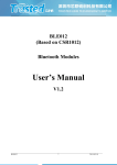
Presented by Thomas T. Smith Manager EMC Test Services Modules provide a quick and easy method to take your product wireless or does it? The focus of this presentation is to: • Briefly discuss what is considered a module • How to determine if an FCC Modular Certification exists • Discuss key items regarding the FCC Modular Certification • What if you want to make changes to the certified module • Types of modular approvals: single, split and limited • Single modular transmitters consist of a completely self-contained radiofrequency transmitter device that is typically incorporated into another product, host or device • Advantages of the Modular approval – Potentially No Additional RF testing is required (only unintentional emissions with the radio inside of your product) – Quicker time to market as design and certification process is complete – Minimal RF/Wireless expertise required if your modular partner is responsive • There are 8 key requirements that need to be met in order for a single modular approval to be allowed • The 8 key requirements can be found in CFR Title 47 Part 15.212 (a)(1) • The radio elements of the module requires a RF Shield • Module is to have buffered modulation/data inputs (need to ensure no excessive data rates or over-modulation • Power Supply regulation on the module • Meet the antenna requirements as discussed in 15.203, 15.204(b) and 15.204(c). • Tested in a Standalone configuration • Permanently affixed label • Module must comply with any other requirements the other complete radio transmitters • Module must comply with any RF Exposure requirements as outlined in 2.1091 and 2.1093 • The FCC ID Number is a unique identifier for each radio product that has been certified. • The FCC ID Number is composed of a prefix and a suffix. • The prefix is also referred to as the Grantee Code • The suffix is chosen by the end customer TFB-PROFLEX02 Suffix Grantee Code • Per the requirements for modular approval. The FCC ID number should be found on the module. • Items Typically Not under confidentiality – – – – – – – User Manual Labels External Photos Internal Photos Test Setup Photos Test Report MPE/SAR evaluation • Items Typically Held under confidentiality – Block Diagram – Schematics – Theory of Operation • Portable devices are defined as transmitting devices designated to be used so that the radiating structure(s) of the device is/are within 20cm of the body of the user • Examples: • SAR is a measure of the amount of radio frequency energy absorbed by the body. • Guidelines on SAR limits and general examples can be found in OET Bulletin 65 and Supplement C Exposure Category Low Threshold General Population (60/fGHz) mW, d < 2.5cm (120/fGHz) mW, d ≥ 2.5cm • Example Calculations: 1. 915MHz 2. 2440MHz : 65.6mW = 18.2dBm d<2.5cm :131.1mW = 21.2dBm 2.5cm<d<20cm :24.6mW = 13.9dBm d<2.5cm :49.2mW = 16.9dBm 2.5cm<d<20cm FCC LIMITS FOR SPECIFIC ABSORPTION RATE (SAR) (A) Limits for Occupational/Controlled Exposure (W/kg) Whole-Body Partial-Body Hands, Wrists, Feet and Ankles 0.4 8.0 20.0 (B) Limits for General Population/Uncontrolled Exposure (W/kg) Whole-Body Partial-Body Hands, Wrists, Feet and Ankles 0.08 1.6 4.0 NOTE 1: See Section 1 for discussion of exposure categories. NOTE 2: Whole-Body SAR is averaged over the entire body, partial-body SAR is averaged over any 1 gram of tissue defined as a tissue volume in the shape of a cube. SAR for hands, wrists, feet and ankles is averaged over any 10 grams of tissue defined as a tissue volume in the shape of a cube. NOTE 3: At frequencies above 6.0 GHz, SAR limits are not applicable and MPE limits for power density should be applied at 5 cm or more from the transmitting device. Note 4: The time averaging criteria for field strength and power density do not apply to general population SAR limit of 47 CFR §2.1093. • Mobile devices are defined as transmitting device designed to be used in other than fixed locations and to generally be used in such a way that a separation distance of at least 20cm is normally maintained between the transmitters radiating structure and the body of the user or nearby persons. • Examples: • For devices that are used in mobile applications an MPE (Maximum Permissible Exposure calculation can be performed in place of an SAR evaluation. • All MPE Calculations are performed at a 20cm separation distance S=Power Density P= Power Input to Antenna G= Power Gain of the antenna in the direction of interest relative to an isotropic radiator R=Distance to the center of radiation of the antenna FCC LIMITS FOR MAXIMUM PERMISSIBLE EXPOSURE (MPE) (A) Limits for Occupational/Controlled Exposure Frequency Range (MHz) Electric Field Strength (E) (V/m) Magnetic Field Strength (H) (A/m) Power Density (S) (mW/cm2) Averaging Time |E|2, |H|2 or S (minutes) 0.3-3.0 3.0-30 30-300 300-1500 1500-100,000 614 1842/f 61.4 --- 1.63 4.89/f 0.163 --- (100)* (900/f2)* 1.0 f/300 5 6 6 6 6 6 (B) Limits for General Population/Uncontrolled Exposure Frequency Range (MHz) Electric Field Strength (E) (V/m) Magnetic Field Strength (H) (A/m) Power Density (S) (mW/cm2) Averaging Time |E|2, |H|2 or S (minutes) 0.3-1.34 1.34-30 30-300 300-1500 1500-100,000 614 824/f 27.5 --- 1.63 2.19/f 0.073 --- (100)* (180/f2)* 0.2 f/1500 1.0 30 30 30 30 30 f = frequency in MHz *Plane-wave equivalent power density NOTE 1: See Section 1 for discussion of exposure categories. NOTE 2: THE AVERAGING TIME FOR GENERAL POPULATION/UNCONTROLLED EXPOSURE TO FIXED TRANSMITTERS IS NOT APPLICABLE FOR MOBILE AND PORTABLE TRANSMITTERS. SEE 47 CFR §§2.1091 AND 2.1093 ON SOURCEBASED TIME-AVERAGING REQUIREMENTS FOR MOBILE AND PORTABLE TRANSMITTERS. • Modifications can be made using the Permissive Change Policy as found in Part 2.1043 and KDB #178919 • Some reasons for a Permissive Change or potentially a new FCC ID Number are: – Adding New Antenna – Using Module in a portable application – Co-Location or use with Multiple radios – Change of FCC ID • No additional testing or Class II permissive Change is required if: 1. The antenna is of same type and equal or lesser gain 2. In addition the in-band and out-band characteristics of the antenna need to be similar • Reasons additional testing and modifications to the Grant would be required – Violation of 1 and 2 above – Different type of antenna Higher Gain Change in cable length or material which creates lower loss Change in layout of PCB trace antennas Antenna connector change Not Allowed: “N”-type, regular “SMA”, standard “BNC” and standard “F” Type Acceptable: Reverse polarity “SMA”, u.Fl, MMCX • Using radio that was certified for Mobile use in a portable configuration – As discussed previously the Grant may not specifically indicate mobile or portable configuration, therefore OEM needs to evaluate the documents to determine proper classification – A module that was certified for mobile use can be used in a portable application if it is evaluated for compliance to the RF Exposure requirements. Typically this would require SAR testing in the host. The Grant of Authorization is then modified using the permissive change policies Usually RF testing of the radio is not required as the procedure and limits for output power do not differ between mobile and portable. • Co-location refers to the use of 2 transmitting devices having radiating structures within 20cm of each other • In addition to the separation distance between the transmitting antennas, one also needs to verify that both transmitters are capable of transmitting at the same time • Co-location testing consists of having both Transmitters transmitting at the same time and then evaluating the spectrum for any intermodulated harmonics or additive effects. • The co-location testing is not limited to 2 radios operating in the same band (2.4GHz Bluetooth and 2.4GHz WiFi), but also in cases where the operating bands are separated (900MHz ISM radio and 2.4GHz Bluetooth) • In many cases OEM’s are using modules “off the shelf” or modules they do not own the Grant of Authorization • As a result if OEM needs to make modifications to the Grant of Authorization it may not always be in their best interest to do a Permissive Change or the Permissive Change may not be possible. – Test Software – Module manufacturer doesn’t want to make any changes – Module manufacturer receives all the benefits • One solution is to perform a Change of FCC ID – Benefits: This allows the OEM to have a unique FCC ID number for the module No RF Testing is necessary unless modifications are made to the module Prevents Module manufacturer from using new antennas or changes certified by the OEM – Additional Responsibilities: Need Permission and signed letter from Module Manufacturer Labeling New User Manual RF Testing may be required Increased cost filing and possibly for testing Need to track any changes made by the module manufacturer • Modular Approval can be a very powerful and effective method to take your product wireless • However understanding the Grant of Authorization and how the product was originally certified is critical • Modifications to the Grant of Authorization to allow for additional flexibility are possible, but they can be costly and affect the overall complexity of using a module • DA 00-1407 Part 15 Unlicensed Modular Transmitter Approval – List the 8 requirements to be compliant for Single Modular Approval • KDB #996369 D01 Module Certification Guide v01r03 – This document outlines modular certification guidelines • KDB #447498 D01 General RF Exposure Guidance v05 – This document discusses Mobile and Portable Device RF Exposure Procedures • KDB #447498 D02 SAR Procedures for Dongle Xmtr v02 – This document discusses SAR testing for dongles • KDB #178919 D01 Permissive Change Policy v05r03 – This document outlines permissive change policies for transmitting devices, including modules • Thomas T. Smith • Manager EMC Test Services • E-mail: [email protected] • Direct: (262) 421-4986 • Main: (262) 375-4400 • www.lsr.com