1
User Manual
SD-14
Sampling Head
070–8286–01
This document applies for firmware version X.XX
and above.
Warning
The servicing instructions are for use by qualified
personnel only. To avoid personal injury, do not
perform any servicing unless you are qualified to
do so. Refer to the Safety Summary prior to performing service.
Please check for change information at the rear
of this manual.
First Edition: May 1993
Last Revised: May 20, 1994
"$) *.3425-&.4 -".5'"$452&% #9 &+42/.*8 )"3 " 3&2*", .5-#&2 /. " 0".&, *.3&24 /2 4"( /2 34"-0&% /. 4)&
$)"33*3 )& '*234 ,&44&2 *. 4)& 3&2*", .5-#&2 %&3*(."4&3 4)& $/5.429 /' -".5'"$452& )& ,"34 '*6& %*(*43 /' 4)&
3&2*", .5-#&2 "2& "33*(.&% 3&15&.4*",,9 ".% "2& 5.*15& 4/ &"$) *.3425-&.4 )/3& -".5'"$452&% *. 4)&
.*4&% 4"4&3 )"6& 3*8 5.*15& %*(*43 )& $/5.429 /' -".5'"$452& *3 *%&.4*'*&% "3 '/,,/73
&+42/.*8 .$ &"6&24/. 2&(/. &+42/.*8 .*4&% *.(%/- 4% /.%/.
/.9&+42/.*8 "0".
&+42/.*8 /,,".% &&2&.6&&. )& &4)&2,".%3
.3425-&.43 -".5'"$452&% '/2 &+42/.*8 #9 &84&2.", 6&.%/23 /543*%& 4)& .*4&% 4"4&3 "2& "33*(.&% " 47/ %*(*4
",0)" $/%& 4/ *%&.4*'9 4)& $/5.429 /' -".5'"$452& &( '/2 "0". '/2 /.( /.( '/2 32"&, &4$
&+42/.*8 .$ /8 &"6&24/. 2*.4&% *. /092*()4 E &+42/.*8 .$ ,, 2*()43 2&3&26&% &+42/.*8 02/%5$43 "2& $/6&2&% #9 ".%
'/2&*(. 0"4&.43 *335&% ".% 0&.%*.( )& '/,,/7*.( "2& 2&(*34&2&% 42"%&-"2+3 ! ".% :
WARRANTY
! " " " ! ! " " ! ! "
" ! ! " " ! " ! " " " " " " ! " "
! " THIS WARRANTY IS GIVEN BY TEKTRONIX WITH RESPECT TO THIS PRODUCT IN LIEU OF ANY OTHER
WARRANTIES, EXPRESSED OR IMPLIED. TEKTRONIX AND ITS VENDORS DISCLAIM ANY IMPLIED WARRANTIES OF
MERCHANTABILITY OR FITNESS FOR A PARTICULAR PURPOSE. TEKTRONIX' RESPONSIBILITY TO REPAIR OR
REPLACE DEFECTIVE PRODUCTS IS THE SOLE AND EXCLUSIVE REMEDY PROVIDED TO THE CUSTOMER FOR
BREACH OF THIS WARRANTY. TEKTRONIX AND ITS VENDORS WILL NOT BE LIABLE FOR ANY INDIRECT, SPECIAL,
INCIDENTAL, OR CONSEQUENTIAL DAMAGES IRRESPECTIVE OF WHETHER TEKTRONIX OR THE VENDOR HAS
ADVANCE NOTICE OF THE POSSIBILITY OF SUCH DAMAGES.
Contents
SDĆ14 User Manual
List of Figures . . . . . . . . . . . . . . . . . . . . . . . . . . . . . . . . . . . . . . . . . . . . . . .
iii
List of Tables . . . . . . . . . . . . . . . . . . . . . . . . . . . . . . . . . . . . . . . . . . . . . . . .
v
Introduction . . . . . . . . . . . . . . . . . . . . . . . . . . . . . . . . . . . . . . . . . . . . . . . . .
1
Safety . . . . . . . . . . . . . . . . . . . . . . . . . . . . . . . . . . . . . . . . . . . . . . . . . . . . . .
3
Electrostatic Discharge . . . . . . . . . . . . . . . . . . . . . . . . . . . . . . . . . . . . . .
5
Probe and Probe Cable Care . . . . . . . . . . . . . . . . . . . . . . . . . . . . . . . . .
7
Installing the Sampling Head . . . . . . . . . . . . . . . . . . . . . . . . . . . . . . . . .
9
Using the Sampling Head . . . . . . . . . . . . . . . . . . . . . . . . . . . . . . . . . . . .
13
Connecting Signals . . . . . . . . . . . . . . . . . . . . . . . . . . . . . . . . . . . . . .
Buttons and Lights . . . . . . . . . . . . . . . . . . . . . . . . . . . . . . . . . . . . . . .
Instrument/Sampling Head Interaction . . . . . . . . . . . . . . . . . . . . .
Displaying a Trace . . . . . . . . . . . . . . . . . . . . . . . . . . . . . . . . . . . . . . .
Slew Rate Limitation . . . . . . . . . . . . . . . . . . . . . . . . . . . . . . . . . . . . .
14
16
17
18
19
Adjusting Parameters . . . . . . . . . . . . . . . . . . . . . . . . . . . . . . . . . . . . . . . .
21
Stored Parameters . . . . . . . . . . . . . . . . . . . . . . . . . . . . . . . . . . . . . . .
Offset Null and Offset Gain . . . . . . . . . . . . . . . . . . . . . . . . . . . . . . .
22
23
Accessories . . . . . . . . . . . . . . . . . . . . . . . . . . . . . . . . . . . . . . . . . . . . . . . . .
25
Standard Accessories . . . . . . . . . . . . . . . . . . . . . . . . . . . . . . . . . . . .
Optional Accessories . . . . . . . . . . . . . . . . . . . . . . . . . . . . . . . . . . . .
25
25
Specifications . . . . . . . . . . . . . . . . . . . . . . . . . . . . . . . . . . . . . . . . . . . . . . .
27
Glossary . . . . . . . . . . . . . . . . . . . . . . . . . . . . . . . . . . . . . . . . . . . . . . . . . . . .
31
Index . . . . . . . . . . . . . . . . . . . . . . . . . . . . . . . . . . . . . . . . . . . . . . . . . . . . . . .
33
i
ii
List of Figures
.,96* >14(0 .&,6&2 4+ 8-* "&251.3, *&) .,96* >"&251.3, *&) 425&682*387 .3 &3 &3) &
"
.,96* >#-* )*38.+< 45?$5 *39 .,96* >378&11.3, & "&251.3, *&) .3 &3 378692*38 .,96* >"? "&251.3, *&) 6438 &3*1 .,96* >"8&3)&6) =22 ((*7746.*7 +46 8-* "? "&251.3,
*&) .,96* >88&(-.3, &3) !*24:.3, 8-* %.6*?462 6493)
88&(-2*38 .,96* >$7* 4+ 8-* 496?478 4938 6493) "4(0*8 &3)
&88*63 .,96* >$7* 4+ 8-* ),*?#&' 9.(0?4938 6493) "4(0*8 .,96* >#-* "&251.3, *&) 3(7 45?$5 *39 .,96* >&1.'6&846 ".,3&1 &+8*6 6*77.3, 9847*8 ),* 4)*
:*6&,.3, 3 .,96* >)/978.3, ++7*8 911 &3) ++7*8 &.3 .,96* >"1*; !&8* .2.8&8.43 SDĆ14 User Manual
iii
iv
List of Tables
,-!% +(') %"&&"% ! &"!'%"%
% *% %&"!& " #' *' ' . ,-$(&'"! '% #'"!& ,-!)%"! !' ! ! #'"!& SDĆ14 User Manual
v
vi
Introduction
)& < ".1-*/( &"% *4 " )*()<1&3'03."/$& 130#&<&26*11&% 4".1-*/(
)&"% 5)"5 $"/ #& */45"--&% */ 5)& &3*&4 *(*5"- ".1-*/( 4$*--0<
4$01&4 5)& < 6-5*<)"//&- /*5 "/% 5)& &3*&4 0..6/*$"<
5*0/4 *(/"- /"-:;&34
NOTE
)& */4536.&/5 ."*/'3".& */ 8)*$) 5)& < *4 */45"--&% .645 )"7& '*3.<
8"3& $0.1"5*#-& 8*5) 5)& < / 4$*--04$01& 03 .645 )"7& 9&$65*7& 30$&4403 "/% *.& "4&0/530--&3 '*3.8"3& 7&34*0/
03 "#07& / 03 4$*--04$01& .645 )"7& 9&$65*7& 30<
$&4403 "/% *.& "4&0/530--&3 '*3.8"3& 7&34*0/ 03 "#07&
)& < ".1-*/( &"% 1307*%&4 5)& '0--08*/( '&"563&4
H
80 */%&1&/%&/5 130#& $)"//&-4 '03 4*(/"- "$26*4*5*0/ "/%
.&"463&.&/54
H
14 "$26*4*5*0/ 3*4& 5*.&
H
50 ; 5:1*$"- #"/%8*%5) '03 )*()<41&&% 4*(/"- $"1563&
H
,W 1 5:1*$"- 130#& -0"%*/( '03 .*/*.6. $*3$6*5 %*4563#"/$&
H
4&3<"%+645"#-& 0''4&5 "5 5)& 130#& 5*1
H
"9*.6. %*41-":&% /0*4& 0' .! 8*5) .! 5:1*$"-
H
#6550/4 '03 26*$, 53"$& "$26*4*5*0/ "/% 4&-&$5*0/
'30. 5)& 4".1-*/( )&"% '30/5 1"/&-
H
)"//&- D &-": "%+645.&/5 3"/(& 0' 14 5:1*$"- 50 "--08 $)"//&%&4,&8 8*5)*/ 5)& )&"%
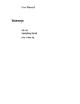
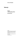
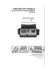
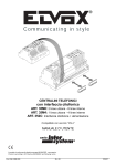
4 4)08/ */ *(63& 5)& 4".1-*/( )&"% )"4 580 */%&1&/%&/5 130#& $)"/<
/&-4 &"$) 8*5) *54 08/ "$26*4*5*0/ $*3$6*53:
)& 4530#& %3*7& 4*(/"- '30. 5)& */4536.&/5 $0/530-4 5)& 5*.*/( 0' 5)& 4530#&
"44&35*0/ 50 &"$) "$26*4*5*0/ 4:45&. 7"3*"#-& %&-": "%+645.&/5 0/ $)"/<
/&- (6"3"/5&&4 4".1-*/( $0*/$*%&/$& #&58&&/ 5)& 580 $)"//&-4 03 "--084
*/5&/5*0/"- 4,&8*/( #&58&&/ $)"//&-4
SDĆ14 User Manual
1
Introduction
#!"
%!"
" "
" $
" !
!" #"
%
#!""
#!"
%!"
Figure 1:ăBlock Diagram of the Sampling Head
!" !! ! ! " " !" ! "# " " !" #&
" " # !! " !" #" " ! " " # " " !" $!" !! #!"! % ! " !" #"
" " " !" "
2
SDĆ14 User Manual
Safety
Terms in Manuals
CAUTION WARNING Terms on Equipment
CAUTION DANGER Symbols in Manuals
Static Sensitive Devices
Symbols on Equipment
DANGER
High Voltage
Protective
ground (earth)
terminal
ATTENTION
Refer to
manual
Grounding the Instrument
SDĆ14 User Manual
3
Safety
Do Not Operate in Explosive Atmospheres
4
SDĆ14 User Manual
Electrostatic Discharge
CAUTION
SDĆ14 User Manual
5
Electrostatic Discharge
6
SDĆ14 User Manual
Probe and Probe Cable Care
$! $ !#%* "&!! (% %( $! !# $ # %% % $ $ # +!#$ $$$
(% %#% #&% $!# &% $ *# # #&%
$$* $ $ # # &$ # % !# '# +
% (# % $ * $$ % % !%& #* )!% #
# %# $ '# % '#%$$ #$ # &$% )#$ % !#'% !# #
SDĆ14 User Manual
H
% # ! !# # ( % %! % $%# # %
H
% !!* )$$' # % % %! % !# H
% # # % !# ' $ $#!# %
#&$ ' !!* )$$' $ !#$$&# % %
$& $ # # $%# '# % H
% !!* )$$' !& # % % % !& $!
$%#&% % ! $% (% !# % $! $
$% )%# % ( % $! )%# % $&$! * !# H
$ * $$ #$ % !# %!$ ! # $#!+
% $ $%# $$ #$
H
$% % !# %! !# %%' '# ('# % !# $ % &$
7
Probe and Probe Cable Care
8
SDĆ14 User Manual
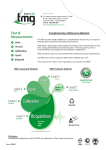
Installing the Sampling Head
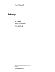
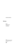
" #" # # !# # "#!$# "$
" # !" # "" ! # !"
$#" ()! $! "&" # !# # "" $#"
()! # #" # " !##" #
## # !" ( #& !##" !% " $"*
# #( #! #& !##" ( !% &! ! '
# &! #*#*#! %!#!
Sampling Head
Compartments
11801B
Sampling Head
Compartments
CSA 803A
Power Only Sampling
Head Compartments
Figure 2:ăSampling Head Compartments in an 11801B and a CSA 803A
SDĆ14 User Manual
9
Installing the Sampling Head
NOTE
2
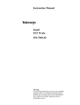
%($!& /!$$ &', '(*, /!, +'% '$* .*+!'&+ '
*!+ '* *!+ !*%/* ' # 1'-* !&+,*-%&, !*%2
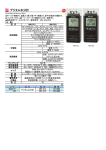
/* (*++ , UTILITY -,,'& & +$, Identify *'% , ,!$!,1 %"'*
%&- '- /!$$ + !+($1 +!%!$* ,' !-* # , 0-,!. *'+2
+'* & !% +'&,*'$$* !*%/* $.$+ !&+, $ TableĂ1:ăMainframe Executive Processor and Time Base/
Controller Firmware Versions Compatible with the SDĆ14
Mainframe Instrument
Firmware Version for SDĆ14 Operation
w
w
w
1'-* %!&*%+ !*%/* '+ &', +,!+1 , *)-!*%&,+ $!+, !&
$ '&,, 1'-* #,*'&!0 +$+ *(*+&,,!. '* -(* !&'*%,!'&
10
SDĆ14 User Manual
Installing the Sampling Head
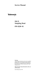
Figure 3:ăThe Identify PopĆUp Menu
! ! CAUTION
"$ ! "# ! " !
! $" " ! SDĆ14 User Manual
11
Installing the Sampling Head
Lock Down
Screw
Sampling
Head
Figure 4:ăInstalling a Sampling Head in an Instrument
12
SDĆ14 User Manual
Using the Sampling Head
%" # '# $ " $ ! $ #! $# $
%$$ # $# !" #
CAUTION
" # !"$( $$ #! !" '$ ) $!
" # !%$ %$$ ( ' $ "
$
!%$ "%$"( %# $ #! !" # # #%#!$ $ " &""& # " & $# " $" #$$ #" &"
!!( & $ %$# $ " " !"$ $ #$"%$ #! ( #$$* $" &" $ '(# %# '"#$
#$"! ' #! # " $ #
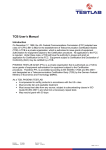
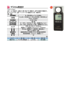
LockĆdown Screw
SELECT CHANNEL
Button
Channel Indicator
Light (Yellow)
Top Channel
Signal Probe Cable
Bottom Channel
Figure 5:ăSDĆ14 Sampling Head Front Panel
SDĆ14 User Manual
13
Using the Sampling Head
Connecting Signals
#%"& "% !! ' ,"( %', "!!' '" ' %('%, (!%
'&' !, ' & *'"(' ''! !, +'% %*% '" ' %('%, '&
/ &" & ' ""*! &'!% .
&&"%& '" ''
#%" '' !' & (% H
%/"%
%"(! '' !'
H
"(%/#"&' H
/' $(/ "(!' %"(! &"'
"(!' %"(! &"'
WireĆForm
Ground Attachment
FourĆPost ECB Mount
Ground Socket
EdgeĆTab ECB Mount
Ground Socket
Figure 6:ăStandard 4Ămm Accessories for the SDĆ14 Sampling Head
NOTE
"' '' '& .
&&"%& % !"' " #' *' "'% &&"%&
"% &( !'(% #%"& )! '"( '% ##%! & & % " !"'
'' #' '" (& ' / #%"& *' !, &&"%& "'% '! '"&
&!' & -
" '' ' *%/"% %"(! '' !' '" ' #%" '# &# ' ")% '
! " ' #%" '# ! '(%! ' & &"*! ! (% ! ! (' ' !
" ' *% '" ' ,"(% %"(! "!('"% (%! ' '' !' ! ' & %'"! '" % ") '
14
SDĆ14 User Manual
Using the Sampling Head
WireĆForm
Ground Attachment
Probe Tip
Figure 7:ăAttaching and Removing the WireĆForm Ground Attachment
FourĆPost Mount
Ground Socket
ECB Mounting Pattern
Signal
D55RD37
(.037" plated
hole)
.200"
Square
Figure 8:ăUse of the FourĆPost ECB Mount Ground Socket and ECB
Pattern
SDĆ14 User Manual
15
Using the Sampling Head
Ground Pad
Figure 9:ăUse of the EdgeĆTab ECB QuickĆMount Ground Socket
Buttons and Lights
! #"" &% "
" $ " !""! !"& " " #"" ! " !""
16
H
" &% " ! " " ! " # " " " ! !& "" " " ! &#
!! " #"" " # ! " "
!&! " ! #" "" "! "
!" " ! " &% " !
H
" &% " ! !"& " ! # " " " " ! !& ! ! " & " "
!& " %$ " " ! " " !" " "
" ! !"& &# !! " #"" "
" ! !" " " !
H
" &% " ! " ! " " !"
" " " ! &# !! " #"" " !
!& "" $ !"! #!"!
" &% " "# ! SDĆ14 User Manual
Using the Sampling Head
Instrument/Sampling
Head Interaction
" -'*&#(! " #- *,. ) &,!, -3-.' )-. ) ." -'*&#(! "
/(.#)(- , )(.,)&& /.)'.#&&3 ,)' ." #(-.,/'(. "- /(.#)(#(&/ 0,.#& -&#(! ( "),#4)(.& -'*&#(! ,. )/ ) (). #,.&3
)(.,)& ."- *,'.,-
."3 , .-%- .". ." #(-.,/'(. *, ),'-
", , .1) -'*&#(! " /(.#)(- ( .". 3)/ ( )(.,)& #,.&3 ,)' ." '#( ,' #(-.,/5
'(.
H
"((& &3 $/-.- ." .#' &3 ) ." "((& +/#-#.#)( ."
&)1, "((& 1#." ,-*. .) ." "((& +/#-#.#)( ." /**,
"((&
3)/ "(! "((& &3 3)/ -")/& &-) $/-. ) -. , .)
$/-.#(! ,'.,- )( *! ), #( ),'.#)( )( ) -.
H
2.,(& "((& ..(/.#)( (&- 3)/ .) (., (/', ,*,-(.5
#(! (3 2.,(& ..(/.#)( .". 3)/ "0 .) "((& " #(.,(& *,) ..(/.#)( .), #- &,3 )/(. ),
) (). /*
. #. #( ." 2.,(& ..(/.#)( -..#(!
) $/-. "((& &3 ), 2.,(& "((& ..(/.#)( *,-- ."
'(/ /..)( )( 3)/, '#( ,' #(-.,/'(. ( -&.
Sampling Head Fnc's ,)' ." '$), '(/ #!/, )/" ." Channel D Delay ), External Channel Attenuation -&.), .)
-. ." %()- .) )(.,)& .". *,'.,
Figure 10:ăThe Sampling Head Fnc's PopĆUp Menu
SDĆ14 User Manual
17
Using the Sampling Head
Programming Interface Commands
/--!.$3 &2/- ! 2%-/4% #/-054%2 4/ 4(% -!).&2!-% ).3425-%.4 6)! 4(%
/2 ;; .4%2&!#% #!. #/.42/, 4(% (!..%, D %,!9 !.$ 84%2.!,
(!..%, 44%.5!4)/. &5.#4)/.3 /& 4(% ;
/2 4(%3% #/--!.$3 <alpha> ).$)#!4%3 4(% 3!-0,).' (%!$ ,/#!4)/. &/2
-!).&2!-% /2 /2 &/2 !. ; 5,4);(!..%, 5.)4 &/2 4(% %2)%3 <alpha> )3 !,7!93 !.$ <ui> ).$)#!4%3 4(% #(!..%, .5-"%2 &/2
4(% #(!..%, 9/5 7!.4 4/ !$*534
H
CH<alpha><ui> CDElay: <NRx>
()3 #/--!.$ 30%#)&)%3 4(% $%,!9 /& 4(% #(!..%, !#15)3)4)/. ,/7%2
#(!..%, 2%,!4)6% 4/ #(!..%, 500%2 #(!..%, <ui> -!9 "% 1 /2 2
H
CH<alpha><ui> EXTAttenuation: <NRx>
()3 #/--!.$ 30%#)&)%3 4(% 84%2.!, (!..%, 44%.5!4)/. /& 4(% 30%#);
&)%$ #(!..%, 7(%2% <NRx> )3 ! &,/!4).';0/).4 !44%.5!4)/. &!#4/2 84%2.!,
(!..%, 44%.5!4)/. )3 ! &%!452% /& 4(% -!).&2!-% %&%2 4/ 4(% &/2 9/52 ).3425-%.4 &/2 -/2% ).&/2-!4)/. /. 4()3 &%!452%
/2 #/-0,%4% ).&/2-!4)/. !"/54 (/7 4/ 53% 4(% ;
4/ $)30,!9 42!#%3 3%%
4(% &/2 9/52 ).3425-%.4
Displaying a Trace
(% &/,,/7).' %8!-0,% 3(/73 9/5 (/7 4/ !#15)2% !.$ $)30,!9 ! 42!#% 7)4(
4(% 3!-0,).' (%!$ !.$ !. ).3425-%.4 /2 4()3 02/#%$52% 9/5 7),, .%%$ /.%
#!",% ).#(%3 /2 ,/.'%2 ! W 4%2-).!4)/. !.$ 4(% /04)/.!, 02/"%
4)0 !$!04%2 &)8452%
ăStep 1:ă.)4)!,):% 4(% ).3425-%.4 4/ $%&!5,4 3%44).'3 53).' 4(% Initialize
3%,%#4/2 7()#( !00%!23 ). 4(% -!*/2 -%.5
ăStep 2:ă/..%#4 4(% 02/"% 4)0 !$!04%2 &)8452% 4/ 4(% #!,)"2!4/2 /54054
53).' 4(% #!",%
ăStep 3:ă.34!,, 4(% W 4%2-).!4)/. /. 4(% &)8452%
ăStep 4:ă/..%#4 4(% 02/"% 4/ 4(% 02/"% 4)0 !$!04%2 &)8452%
ăStep 5:ă2/- 4(% 2)''%2 -!*/2 -%.5 3%4 4(% 42)''%2 3/52#% 4/ ).4%2.!,
ăStep 6:ă2%33 4(% "544/. .%!2%34 4(% 3!-0,).' (%!$
).054 9/5 (!6% #/..%#4%$ 4/ 4(% #!,)"2!4/2
(% 9%,,/7 ,)'(4 /. 4(% 3!-0,).' (%!$ ",).+3 ).$)#!4).' 4(!4 4(% #(!..%,
!#15)3)4)/. #)2#5)4 )3 %.!",%$ !.$ /54054 &2/- 4(% #(!..%, )3 4(% 3%,%#4%$
42!#%
ăStep 7:ă2%33 4(% "544/. !"/6% 4(% 3!-0,).' (%!$3
$)30,!9 3(/5,$ !00%!2 4(!4 )3 3)-),!2 4/ )'52% 18
SDĆ14 User Manual
Using the Sampling Head
Figure 11:ăCalibrator Signal after Pressing Autoset (Edge Mode),
Averaging On
Slew Rate Limitation
SDĆ14 User Manual
19
Using the Sampling Head
20
SDĆ14 User Manual
Adjusting Parameters
. "%!# ' %! $ %&$&"# $*& + &# $
$#($#' +( $#!, %&$ !&($# $+*& ,$) # )' ( $#(&$!'
$ ( "#&" #'(&)"#( ($ $%("- (+$ %&"(&' $# ( '"%!#
H
'( #)!!
H
'( #
$ ( ( '( )&, $&" ( . "%!# ,$) ", +#( ($
)'( '"%!# %&"(&' +#*& ,$) * "$* ( '"%!#
($ #$(& $"%&("#( ( "#( ("%&()& ' #
"
_ '# ( %&"(&' +& !'( )'( $& ##! !, '
)'( ( ( ($&, ( %&"(&' & '( # # #*&$#"#( +( #
"#( & ("%&()& $ _
NOTE
$) # )'( '"%!# %&"(&' ( #, (" $+*& )&# (
#'(&)"#(' +&".)% %&$ ( *!)' ", # ' ( ("%&()&
*&' $) '$)! )'( ( '"%!# %&"(&' $#!, (& (
#'(&)"#( ' # $# $& ( !'( "#)('
()! %&$)& $& %&$&"# (' )'("#(' %#' $# (
#'(&)"#( $& # &' '!!$'$% $& &' $"")#.
($#' #! #!,-& ,$) # )' ( ## )&, ()& ($
)'( '"%!# %&"(&'
SDĆ14 User Manual
21
Adjusting Parameters
Stored Parameters
" $ # "! $ ! "! ! ! "! #$ " $! " ! $ ! "! $ $! ! # &
$ ! ! # $! # !&
#" $! # "! !
! $ #& #&
$! % ! ! $! ! ! "! &
$! ! "! ! $ !
"! $ ! "! "! $ $! ! 22
SDĆ14 User Manual
Adjusting Parameters
Offset Null and Offset
Gain
$% & &$%% # '$ &(% $% %% * !#$%
% $! !# $ &$%% %'* +# $ % $% #&%#*
% $! !# $ %% !&% $ '#$ &%!&%
$% &$%% %$ % #"&$% $% # % &$# %
% $$%'%* % !# $% #&%
$% & $% # % % &$% ##%* $&#%$
% ( ##% $ &% ' % '&$ # * &#$ #$ $,
!* % %# ( $ ##%
Adjusting Offset Null and Offset Gain
# % $%#&% $% & $% # &$% &$ &% %,
!# &# # % &#* & $ &# % #
$&# &$% $&% &$*
&$% $% & $% % % !# %! % % )! $
## %% % &% % $% !# &# ( % $%#&% $
'
Figure 12:ăAdjusting Offset Null and Offset Gain
SDĆ14 User Manual
23
Adjusting Parameters
24
SDĆ14 User Manual
Accessories
Standard
Accessories
$! "*''*2%)# ./) - !..*-%!. -! +-*1% ! 2%/$ /$! 5
H
/$%. ()0' !&/-*)%3 +-/ )0(!
H
!&/-*)%3 +-/ )0(!
H
-*! /%+ +-*/!/%1! *1!-. !&/-*)%3 +-/ )0(!- H
'! (-&!- .!/ !&/-*)%3 +-/ )0(!- H
%-!5"*-( #-*0) //$(!)/. !&/-*)%3 +-/ )0(!- H
*0-5+*./ (*0)/ #-*0) .*&!/. !&/-*)%3 +-/ )0(!
H
#!5/ ,0%&5(*0)/ #-*0) .*&!/. !&/-*)%3 +-/ )0(!
* */%) -!+'!(!)/. -!"!- /* !&/-*)%3 +-* 0/. /'*# *- *)// 4*0'*' !&/-*)%3 "%!' -!+-!.!)//%1!
Optional Accessories
SDĆ14 User Manual
$! "*''*2%)# *+/%*)' !..*-%!. (4 ! +0-$.! "*- 0.! 2%/$ /$!
5 *- !/%'! %)"*-(/%*) ) +-%!. -!"!- /* !&/-*)%3 +-* 0/.
/'*# *- *)// 4*0- '*' !&/-*)%3 "%!' -!+-!.!)//%1!
H
'%-/%*) "%3/0-! !&/-*)%3 +-/ )0(!- H
(+'%)# $! !3/!) !- '! !&/-*)%3 +-/ )0(!- *)! (!/!- /2* (!/!-
25
Accessories
26
SDĆ14 User Manual
Specifications
TableĂ2:ăAcquisition Electrical Specifications
Characteristics
Specifications
Small Signal Rise Time
140 ps or less, 10% to 90%
Small Signal Aberrations
distal to 1.5 ns
+12% to -25% typical
1.5 ns to 4 ns
+1% to -3% typical
4 ns to 30 ns
"2% typical
after 30 ns
"1% typical
Bandwidth
3 GHz typical (-3 dB)
Sampling Repetition Rate
SDĆ14 User Manual
Maximum
200 kHz
Minimum
100 Hz
Maximum Safe Input Signal Voltage
"15 V (DC + peak AC)
Dynamic Range
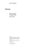
7 VpĆp AC, limited above 570 MHz
1 dB compression points are:
ą4 VpĆp AC at 1 GHz typical
ą2 VpĆp AC at 2 GHz typical
ą1.33 VpĆp AC at 3 GHz typical
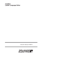
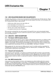
or, slew rate limited to t12.5 V/ns
typical (see Figure 13 for slew rate
limitations)
Displayed noise
8 mVRMS maximum;
7 mVRMS typical
Offset range
"3.5 V
Offset accuracy
"(20 mV + 1%)
Input Impedance
100 k typical
0.475 pF typical
Time matching
Adjustable; 350 ps range
27
Specifications
Vin
VpĆp X fGHz = 4
fGHZ
Figure 13:ăSlew Rate Limitation
28
SDĆ14 User Manual
Specifications
TableĂ3:ăEnvironmental and Mechanical Specifications
Characteristics
Specifications
$"#-
"+', )1
$"#-
'' $(
$-#
'' $(
*-#
'' $(
+) ("-#
' $(
'$ (- '* +-.+
* +-$("
_ -) _ _ -) _ )(2)* +-$("
_ -) _ _ -) _ &-$-.
* +-$("
-) %' !
-
)(2)* +-$("
-) %' !
-
.'$$-0
SDĆ14 User Manual
-) + &-$/ #.'$$-0 - .* -)
_ _
29
Specifications
30
SDĆ14 User Manual
Glossary
Autoset
! $ ! Channel
" #
Channel Number
& "$ $ &
Default Measurement Parameter
! ! ! &
Initialize
$ " Internal Clock
$% " Setting
$ ! Smoothing
$ % ! $ " %
$
Trigger
! $ Waveform
! SDĆ14 User Manual
31
Glossary
32
SDĆ14 User Manual
Index
A
#!"## "! !$#" ""!" !! "# )# $)$# !$
"# '#! $!)"# $# !$ ")
# # ! # #! '#$! ! # %!" "#! &!)! !$ ### '#! $"#
!$#!( !" # B
$!( R
F
!! "# " ! #!" ! E
)# $)$# !$
"# SDĆ14 User Manual
% " # $"# #!( $#" $!)"# $# !$ "#
!# $##" #" !" I
S
!#!"
"# "# $ "#! SELECT CHANNEL $## #! !#! %$" "# &# C
!" ! T
O
! "( "# $"# "# $
$"# "!# U
"! "##" P
!#!" $"# ! # #! '#$! W
!)! !$ ### ! # %!" 33
34