1
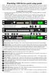
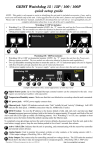
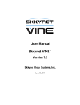
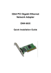
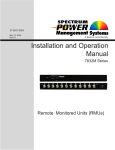
NOTE: This guide is only meant to assist in identifying your Geist GRS-series unit and its included accessories,
if any, and to assist you with initial setup of the unit. It does not describe all of the unit’s features and capabilities
in detail. Please refer to the full user’s manual, available from our web site at www.geistglobal.com, for complete
information about how to use all of the unit’s capabilities. Also note that for purposes of the following
instructions, all members of the GRS family behave identically, so “GRS-series monitoring unit” or “GRS unit”
are used generically to refer to all models, and only screenshots from the GRSE-B are shown.)
Geist GRS-series kit will include:
Ÿ GRSE-B, GRSE2X16, GRSMini163, GRSO, or GRSO-POE environmental monitor
(NOTE: GRSO-POE is a GRSO with the Power-over-Ethernet option installed. The two models are
otherwise identical in function and capabilities. The GRSO is the only model with a PoE option
available.)
Ÿ +6Vdc power supply (unless the “no power supply” option was chosen when the unit was ordered)
GRSE-B / GRSE2X16 (GRSE-B will not have LCD display or “horn off” button)
(sample illustrations only; actual
appearance of unit may vary)
1
2
3
OF
F
C
J K L
TIV
AC
E
C D
A B
C
REMOTE SENSORS
REMOTE SENSORS
GRSO / GRSO-POE
F
Analog Inputs
3
C
G H
RELAY1
RELAY2
M
IP RESET
+6VDC ON
D
RELAY3
TEMPF
74.09
OF
F
E
REBOOT
IDL
E
TIV
A
B
C
IP RESET
2
HO
RN
AC
ON +6VDC
1
IDL
E
E
GRSMini163
BO
OT
C
REMOTE SENSORS
RE
IP RESET
TEMPF
74.09
HO
RN
LIG
HT
SE
NS
OR
TIV
E
AC
ON +6VDC
IDL
E
TEMP &
AIRFLOW
SENSORS
REMOTE SENSORS
C 1 C 2 C 3 C 4 C 5 C 6
N
NN
NN
N
C C OC C OC C O
DC power jack: +6VDC power supply connects here.
Ethernet jack: Right LED indicates “link” when lit; left LED indicates network activity when blinking.
RESET button: To reset the IP address to the factory default of 192.168.123.123 and clear any User
Account username/password settings, use a pushpin or paperclip to press and hold this pinhole button for
approximately 20 seconds, until both of the red Active and Idle LEDs light up solidly (no blinking pattern).
To completely erase all settings and reset the unit to factory defaults, disconnect power from the unit, push in the
reset button, reapply power, keep the reset button pushed in for at least 5 seconds, then release.
D
E
F
G
H
REBOOT button: reboots the unit (GRSMini163, GRSO, and GRSO-POE only)
Digital Sensor jacks: Up to sixteen Digital Bus-type external sensors may be connected. (may require an
external port-splitter, sold separately)
Analog Inputs: for dry-contact switches, relay contacts, or analog sensors with 0 ~ +5Vdc output voltages.
Relay Outputs: (GRSO and GRSO-POE only) Dry-contact relays for controlling external low-voltage
devices. The LEDs under the terminal block shows the relay states: de-energized (red) or energized (green).
Active / Idle LEDs: Indicates that the unit is operating, and communicating with the sensor-bus controller
and external sensors (if any).
Temperature/Humidity/Airflow sensor: Make sure that this is not blocked or covered up when the unit
is mounted. (GRSE-B and GRSE2X16 only)
Light sensor: (GRSE-B and GRSE2X16 only) Measures ambient light level.
J
K
HORN OFF button: (GRSE2X16, GRSO, and GRSO-POE only) Silences the internal alarm buzzer even
L if the alarm condition which tripped it has not yet been cleared.
LCD status display: (GRSE2X16, GRSO, and GRSO-POE only) Displays unit status information and
M sensor
measurements.
Geist GRS-series quick-setup pack-in sheet, 130823A-GD
1
http://www.geistglobal.com/support
“QUICK-START” NETWORK SETUP:
By default, the unit’s IP address is set to 192.168.123.123 from the factory. To access the unit for the first
time, you will probably need to temporarily change your computer’s network settings to match the
192.168.123.xxx subnet.
To set up the GRS-series monitoring unit, connect it to a PC’s Ethernet port (some PC’s may require a special
“crossover” Ethernet cable to make this type of direct connection), connect the 6V power supply, then follow the
appropriate instructions for your PC’s operating system:
● FOR WINDOWS 2000 / XP / SERVER2003: Click the Start button,
choose Settings, then Network Connections.
● FOR WINDOWS 7 / SERVER2008: Click the Start button, then choose
Control Panel → Adjust Your Computer’s Settings → Network & Sharing
Center → Change Adapter Settings.
Locate the entry under LAN or High-Speed Internet which corresponds to the
network card (or “NIC”) which the GRS unit is connected to. (Most PCs only
have a single NIC installed, but a WiFi connection will also show as a NIC,
so be sure to choose the correct entry.) Double-click on the network adapter’s
entry in the Network Connections list to open its status dialog box, then click
the Properties button to open the Local Properties window (fig.1).
Find the entry titled “Internet Protocol (TCP/IP)” in the list, then click the
Properties button to open the Internet Protocol Properties window (fig.2).
If you see more than one TCP/IP entry, the PC may be configured for IPv6
support as well as IPv4; make sure to select the entry for the IPv4 protocol.
Make sure you write down any settings shown here before changing them!
(fig.1)
Choose the Use the following IP address option, then set IP address to
192.168.123.100 and Subnet Mask to 255.255.255.0. For this initial
setup, Default Gateway and the DNS Server entries can be left blank. Select
OK, then OK again to close both the Internet Protocol Properties and Local
Properties windows.
● FOR MAC OS X: Click the System Preferences icon on the Dock, and
choose Network. Select Built-in Ethernet from the Show drop-down list to
display the Mac’s Ethernet card (“NIC”) settings, then choose the TCP/IP (fig.2)
settings, as shown in (fig.3). Make sure you write down any settings shown
here before changing them!
Select Manually from the Configure IPv4 drop-down list, then set IP address
to 192.168.123.100 and Subnet Mask to 255.255.255.0. (The Router
and DNS Servers can be left blank for this initial setup.) Click Apply Now to
make the settings take effect.
Once the NIC settings are configured properly, you should be able to access
the GRS unit by typing http://192.168.123.123 into the address bar of
your web browser. The unit’s Sensors page will come up by default; click the (fig.3)
Config tab on the left-hand side of the web page to bring up the configurationsettings page, then click the Network sub-tab to set the Network parameters
(fig.4) as needed. The unit’s IP Address, Subnet Mask, Gateway, and DNS
settings can either be assigned manually, or acquired via DHCP. (For more
information, refer to “Assigning an IP Address” in the GRS-series User’s
(fig.4)
Manual, available for download from our web site at
http://www.geistglobal.com/support)
Note that the new settings will take effect instantly when Save Changes is clicked, so the browser will no longer
be able to reload the web page from the 192.168.123.123 address and will probably display a “page not found”
or “host unavailable” message. This behavior is normal. Once you have finished configuring the unit's IP
address, simply repeat the steps above, and change the PC’s NIC card settings back to the ones you wrote down
prior to changing them, to restore the PC’s normal network and internet settings.
Geist GRS-series quick-setup pack-in sheet, 130823A-GD
2
http://www.geistglobal.com/support
SETUP EXAMPLES TO TEST YOUR GEIST GRS-SERIES MONITORING UNIT:
Note: The following instructions assume that you have successfully connected the unit to a network, assigned it
an IP address, and have been able to bring up its Sensors page in your web browser using the “Quick-Start
Network Setup” instructions on the preceding page.)
Before the GRS unit can log data, its real-time clock must be set
to the correct time. The System Clock settings are on the ConfigAdmin page; click the Config tab on the left-hand side of the web
page to bring up the configuration-settings page, click the Admin
sub-tab, then scroll down the page until you find the time-settings
block, as shown here.
The clock can either be set manually, or it can be automatically
synced to an NTP time server. By default, Set Clock Method is
set to Manual-GMT; just fill in the Year, Month, Day, Hour,
Minutes, and Seconds fields, as shown here. Note that the GRS
unit uses a 24-hour clock format; i.e. 8AM would be represented
as 08:00:00, while 8PM would be 20:00:00.
The unit's time is always set in GMT (Greenwich Mean Time). To convert this to your local time, set the
appropriate GMT to local offset (specified as + or – the appropriate amount in hours and minutes, i.e. –05:00 for
U.S Eastern Standard Time, +10:00 for East Australia Time, etc.) for your particular time zone. Then click Save
Changes, and the clock will be set. If Daylight-Saving Time is in effect in your area, be sure to add +1 to the
offset, as appropriate (i.e. use –04:00 for U.S Eastern Daylight Time instead of –05:00.)
To have the unit set the time automatically via NTP, change Set Clock Method to NTP, then click Save Changes.
Note, however, that for this to work, you will need to have correctly set the Gateway and DNS Servers in the
Network settings block, so that the unit is able to reach the outside internet to look up the NTP server’s address
and communicate with it. If these settings are not correct, or if the network’s firewall settings are not set up to
allow the unit to access the outside internet, NTP mode will not work.
Next, the Email settings on the Config-Monitoring page need to
be configured, for the unit to be able to send alerts. If you plan to
use an external SMTP server or a “hosted” service such as Gmail
or AOL, you will need to obtain the correct SMTP settings for
your account from those services.
The GRS-series monitoring unit will only work with a standard
SMTP mail server. It does not support IMAP, or the proprietary
MAPI/RPC protocol used by Microsoft Exchange and Outlook.
(The unit can use an Exchange server to send e-mails, if the
Exchange server is set up to allow SMTP connections; however,
this may require some additional configuration of the Exchange server to allow the unit to connect to it properly.
Please consult Appendix B of the GRS-series User’s Manual for more information on this.) Therefore, if you
need to contact your service provider to get the correct settings, you may need to explicitly mention that you are
not setting up Outlook, or a browser-based e-mail client, on a Windows or Mac computer, in order to get the
correct “generic” SMTP settings from them.
To send e-mails through a Gmail account, for example, the settings would be programmed as follows:
Protocols:
Server:
Port:
“From” E-mail address:
Username:
Password:
ESMTP/TLS/SSL
smtp.gmail.com
587
complete Gmail e-mail address (i.e. [email protected])
complete Gmail e-mail address (i.e. [email protected])
Gmail login password
Then put the e-mail addresses you want to have e-mail alerts sent to into the To E-mail Address fields. Only one
address can be entered into each To E-mail Address field; you cannot “stack” a list of recipients, i.e.
“[email protected]; [email protected]; [email protected]”, within a single To E-mail Address entry.
Geist GRS-series quick-setup pack-in sheet, 130823A-GD
3
http://www.geistglobal.com/support
Once the correct e-mail server settings have been entered, click Save Changes, then click Send Test Email to
have the unit send a test message. If you do not receive the test message within a couple of minutes, double-check
the settings you entered above The most common issues are using the wrong login credentials (username and
password), the wrong Protocols settings, or a network problem which prevented the GRS unit from being able to
reach the e-mail server at all. Note that, as described with the NTP time settings above, the Network settings must
be correct; if the Gateway and DNS Servers settings are not set properly, the unit will not be able to reach the
SMTP mail server, and will not be able to send e-mails.
Additionally, be sure to check your e-mail client’s spam folder, to make sure the test message wasn’t accidentally
marked as spam.
Once you have gotten the GRS-series monitoring unit to send a test e-mail, you can also test its ability to send
actual alarms by setting a temperature alarm on the Alarms page, then warming the sensor to trip the alarm.
First, go to the Sensors page, and take note of the current temperature.
Next, go to the Alarms page, click Add New Alarm, then use the
drop-down boxes to select the “Temperature (F)” or
“Temperature (C)” reading (whichever scale you prefer), set Trips
if to “Above”, then set threshold to a couple of degrees higher
than the current temperature. On the right-hand side, set a
checkbox on at least one of the E-mail addresses in the list – and be sure that the actual e-mail address is shown
next to the checkbox; if the checkbox simply reads “(Email 1)”, “(Email 2)”, etc., then that checkbox doesn’t have
a valid Destination e-mail address programmed into it on the Config page yet, and putting a check in that box
won’t send any messages.
For now, leave the Alarm must remain tripped for [ ](min) before notification setting at “0” and and Repeat
every: at No Repeat, and click Save Changes.
To trip the alarm, return to the Sensors page so that you can see the
current temperature, then simply warm the GRS unit’s sensor by a
few degrees by blowing warm air at it. When the temperature
exceeds the threshold limit, the status messages in the upper-right
corner of the web page should change to show “1 Tripped” alarm,
and the temperature reading itself should turn red. (Some browsers
may require you to manually refresh the web page to see this.) If
the unit’s e-mail server settings are properly configured, within a
few moments you should also receive an e-mail which says
“GRSE: Temperature - High TRIP” in the subject line, and shows
both the alarm threshold and the current temperature in the message
body.
Allow the sensor to cool off again, and when the temperature drops a full degree below the threshold limit you
set, the “Tripped” message should disappear from the web page, the current-temperature reading will turn black
again, and you should receive an e-mail with a subject line of “GRSE: Temperature - Cleared”.
If you have successfully managed to perform the above steps, then... congratulations! The unit is now correctly
set up for your network and SMTP service, and is ready to use. More complete information about all of the unit’s
functions and capabilities can be found in the GRS-series User’s Manual. Clicking the Help tab on the unit’s web
page will open a new browser window to the “Support” area of our web site; the manual can be downloaded as a
PDF file from there.
If you have not been able to complete the above steps successfully, the full User’s Manual can be found by going
to www.geistglobal.com and looking under “Support”, then look for the “Instruction Manuals” link under the
“Monitor” category. If the information provided in the User’s Manual does not help in overcoming whatever
difficulties you may be having, technical support is available by sending an e-mail to
[email protected], and we will be glad to assist you.
Geist GRS-series quick-setup pack-in sheet, 130823A-GD
4
http://www.geistglobal.com/support