1
UM1660
User manual
Getting started with the STM32F401 Discovery kit
Introduction
This document describes the software, firmware environment and development
recommendations required to build an application around the STM32F401 Discovery kit
(32F401CDISCOVERY) with demonstration firmware (STSW-STM32136).
The STM32F401 Discovery kit is a low-cost and easy-to-use development kit to quickly
evaluate and start applications with an STM32F4 series ARM® 32-bit Cortex™-M4
high-performance microcontroller. Before installing and using the product, please accept the
Evaluation Product License Agreement from www.st.com/stm32f4-discovery.
For more information on the STM32F401 Discovery kit, visit www.st.com/stm32f4-discovery.
To order the STM32F401 Discovery kit, use the STM32F401C-DISCO order code.
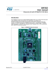
Figure 1. STM32F401 Discovery board: STM32F401C-DISCO
USB ST-LINK
STM32F401C
microcontroller
Extension headers
User button
Reset button
Audio jack
USB_OTG_FS
References
•
•
•
•
•
September 2013
STM32F401xB STM32F401xC datasheet
STM32F40xxx advanced ARM®-based 32-bit MCUs reference manual (RM0344)
Discovery kit for STM32F401 line (UM1669)
Getting started with STM32F401 Discovery software development tools (UM1671)
Forum: user question/discussion
DocID025116 Rev 1
1/11
www.st.com
Contents
UM1660
Contents
1
2
3
2/11
Hardware configuration and layout . . . . . . . . . . . . . . . . . . . . . . . . . . . . . 4
1.1
Features . . . . . . . . . . . . . . . . . . . . . . . . . . . . . . . . . . . . . . . . . . . . . . . . . . . 4
1.2
STM32F401x microcontroller . . . . . . . . . . . . . . . . . . . . . . . . . . . . . . . . . . . 4
1.3
System requirements . . . . . . . . . . . . . . . . . . . . . . . . . . . . . . . . . . . . . . . . . 5
1.4
Powering up the board . . . . . . . . . . . . . . . . . . . . . . . . . . . . . . . . . . . . . . . . 5
1.5
Reset the board . . . . . . . . . . . . . . . . . . . . . . . . . . . . . . . . . . . . . . . . . . . . . 6
1.6
Hardware block diagram . . . . . . . . . . . . . . . . . . . . . . . . . . . . . . . . . . . . . . 6
Firmware package . . . . . . . . . . . . . . . . . . . . . . . . . . . . . . . . . . . . . . . . . . . 7
2.1
Package description . . . . . . . . . . . . . . . . . . . . . . . . . . . . . . . . . . . . . . . . . . 7
2.2
Programming firmware application . . . . . . . . . . . . . . . . . . . . . . . . . . . . . . . 7
2.2.1
Programming application . . . . . . . . . . . . . . . . . . . . . . . . . . . . . . . . . . . . . 8
2.2.2
Run pre-loaded demo . . . . . . . . . . . . . . . . . . . . . . . . . . . . . . . . . . . . . . . 8
Revision history . . . . . . . . . . . . . . . . . . . . . . . . . . . . . . . . . . . . . . . . . . . 10
DocID025116 Rev 1
UM1660
List of figures
List of figures
Figure 1.
Figure 2.
Figure 3.
Figure 4.
Figure 5.
STM32F401 Discovery board: STM32F401C-DISCO . . . . . . . . . . . . . . . . . . . . . . . . . . . . . 1
STM32F401C-DISCO power sources . . . . . . . . . . . . . . . . . . . . . . . . . . . . . . . . . . . . . . . . . 5
Hardware block diagram . . . . . . . . . . . . . . . . . . . . . . . . . . . . . . . . . . . . . . . . . . . . . . . . . . . . 6
Package contents . . . . . . . . . . . . . . . . . . . . . . . . . . . . . . . . . . . . . . . . . . . . . . . . . . . . . . . . . 7
Hardware environement . . . . . . . . . . . . . . . . . . . . . . . . . . . . . . . . . . . . . . . . . . . . . . . . . . . . 8
DocID025116 Rev 1
3/11
3
Hardware configuration and layout
UM1660
1
Hardware configuration and layout
1.1
Features
The STM32F401 Discovery offers the following features:
•
STM32F401VCT6 microcontroller featuring 256 KB of Flash memory, 64 KB of RAM in
an LQFP100 package
•
On-board ST-LINK/V2 with selection mode switch to use the kit as a standalone STLINK/V2 (with SWD connector for programming and debugging)
•
Board power supply: through USB bus or from an external 5 V supply voltage
•
External application power supply: 3 V and 5 V
•
L3GD20, ST MEMS motion sensor, 3-axis digital output gyroscope.
•
LSM303DLHC, ST MEMS system-in-package featuring a 3D digital linear acceleration
sensor and a 3D digital magnetic sensor.
•
MP45DT02, ST MEMS audio sensor, omnidirectional digital microphone
•
CS43L22, audio DAC with integrated class D speaker driver
•
Eight LEDs:
–
LD1 (red/green) for USB communication
–
LD2 (red) for 3.3 V power on
–
Four user LEDs:
LD3 (orange), LD4 (green), LD5 (red) and LD6 (blue)
–
Two USB OTG LEDs:
LD7 (green) VBus and LD8 (red) over-current
•
Two pushbuttons (user and reset)
•
USB OTG with micro-AB connector
• Extension header for LQFP100 I/Os for a quick connection to the prototyping board and
an easy probing
1.2
STM32F401x microcontroller
The STM32F401x device is based on the high-performance ARM® 32-bit Cortex™-M4
RISC core operating at a frequency of up to 84 MHz. The Cortex-M4 core features a floating
point unit (FPU) single precision which supports all ARM single-precision data-processing
instructions and data types. It also implements a full set of DSP instructions and a memory
protection unit (MPU) which enhances application security.
The STM32F401x device incorporates high-speed embedded memories (Flash memory up
to 256 Kbytes, up to 64 Kbytes of SRAM), up to 4 Kbytes of backup SRAM, and an
extensive range of enhanced I/Os and peripherals connected to two APB buses,
two AHB buses and a 32-bit multi-AHB bus matrix.
4/11
DocID025116 Rev 1
UM1660
1.3
Hardware configuration and layout
System requirements
•
Windows PC (XP, Vista, 7)
•
USB type A to Mini-B cable
•
ST-LINK/V2
•
Supported IDE are EWARM (IAR Embedded Workbench®), MDK-ARM™ and
Atollic TrueSTUDIO®
Note:
Required information to download and install desired IDE and ST-LINK/V2 are detailed in
Getting started with STM32F401 Discovery software development tools (UM1671).
1.4
Powering up the board
The STM32F401C-DISCO board can be powered up from three sources.
•
USB ST-LINK: To power the board from the USB connector CN1, use the 'USB type A
to Micro-B' cable and connect it between the host and the board USB connector CN1.
•
Two external sources: DC power supply can be inserted in the GND and
3 V (or 5 V) pin.
Figure 2. STM32F401C-DISCO power sources
USB ST-LINK (CN1)
DocID025116 Rev 1
5/11
10
Hardware configuration and layout
1.5
UM1660
Reset the board
There are three ways to reset the board:
1.6
•
Push the reset button mounted on the STM32F401C-DISCO.
•
Remove and reinsert the USB cable.
•
The MCU can also be reset by debuggers.
Hardware block diagram
The STM32F401C-DISCO is designed around the STM32F401xC microcontroller in a
100-pin LQFP package. Figure 3 illustrates the connections between the STM32F401xC
and its peripherals (STLINK/V2, pushbutton, LED, USB and connectors).
Please refer to Schematic Pack on www.st.com/stm32f4-discovery for more details.
Figure 3. Hardware block diagram
Mini-USB
SWD
Embedded
ST-LINK/V2
STM32F401VGT6
I/O
I/O
RESET
LEDs
LD3...LD8
B2
RESET
MP45DT02
B1
USER
CS43L22
Mini-Jack
Micro-USB
Header
Header
I/O
L3GD20
LSM303DLHC
MS31947V1
6/11
DocID025116 Rev 1
UM1660
2
Firmware package
Firmware package
To get started with the STM32F401 Discovery kit, a firmware package that contains a set of
IPs examples and demonstrations of some features are available on
www.st.com/stm32f4-discovery.
2.1
Package description
The STM32F401 Discovery firmware applications and related documentation are provided
in one single package and supplied in one single ZIP file. The extraction of the ZIP file
generates one folder, STM32F401-Discovery_FW_VX.Y.Z, which contains the following
subfolders:
Figure 4. Package contents
You can run examples provided within this package. A set of examples for each peripheral
are ready to be run.
2.2
Programming firmware application
To start programming, user must:
•
Install the preferred Integrated Development Environment (IDE).
•
Install the ST-LINK/V2 driver from the ST web site.
DocID025116 Rev 1
7/11
10
Firmware package
2.2.1
UM1660
Programming application
To program application (demonstration or example), follow the sequence below:
1.
2.
3.
4.
5.
6.
Open the application folder
Choose the desired IDE project
Double click on the project file (ex. STM32F401-Discovery_Demo.eww for EWARM)
Rebuild all files: Project->Rebuild all
Load project image: Project->Debug
Run program: Debug->Go
Please refer to Getting started with STM32F401 Discovery software development tools
(UM1671) for more details.
2.2.2
Run pre-loaded demo
To run and develop any firmware applications on your STM32F401 Discovery board, the
minimum requirements are as follows:
–
–
Windows PC (XP, Vista, 7)
‘USB type A to Mini-B' cable, used to power the board (through USB connector
CN1) from host PC and connect to the embedded ST-LINK/V2 for debugging and
programming.
Additional hardware accessories will be needed to run some applications:
–
‘USB type A to Micro-B' cable, used to connect the board (through USB connector
CN5) as USB Device to host PC.
Establish the connection with the STM32F401 Discovery board as shown in Figure 5.
Figure 5. Hardware environement
8/11
DocID025116 Rev 1
UM1660
Firmware package
The demonstration software is already preloaded in the Flash memory on the board. The
latest versions of the demonstration source code and associated documentation can be
downloaded from www.st.com/stm32f4-discovery.
Follow the sequence below to configure the STM32F401 Discovery board and launch the
DISCOVER application:
1.
Ensure that the jumpers JP2 and CN3 are set to "on" (Discovery mode).
2.
Connect the STM32F401 Discovery board to a PC using a USB cable type A/mini-B
through the USB ST-LINK connector CN1, to power the board. The LED LD2 (PWR)
will light up and the four LEDs between the buttons B1 and B2 start blinking.
3.
Press the user button B1 to enable the MEMS sensor. The four LEDs will indicate the
board motion direction and speed. When connected to a PC with a second USB type
A/micro-B cable through CN5, the board will be recognized as a standard mouse.
4.
The demo software, as well as other software examples that allow you to discover the
STM32 F4 series features, are available on www.st.com/stm32f4-discovery.
5.
Develop your own applications starting from the examples.
DocID025116 Rev 1
9/11
10
Revision history
3
UM1660
Revision history
Table 1. Document revision history
10/11
Date
Revision
11-Sep-2013
1
Changes
Initial release.
DocID025116 Rev 1
UM1660
Please Read Carefully:
Information in this document is provided solely in connection with ST products. STMicroelectronics NV and its subsidiaries (“ST”) reserve the
right to make changes, corrections, modifications or improvements, to this document, and the products and services described herein at any
time, without notice.
All ST products are sold pursuant to ST’s terms and conditions of sale.
Purchasers are solely responsible for the choice, selection and use of the ST products and services described herein, and ST assumes no
liability whatsoever relating to the choice, selection or use of the ST products and services described herein.
No license, express or implied, by estoppel or otherwise, to any intellectual property rights is granted under this document. If any part of this
document refers to any third party products or services it shall not be deemed a license grant by ST for the use of such third party products
or services, or any intellectual property contained therein or considered as a warranty covering the use in any manner whatsoever of such
third party products or services or any intellectual property contained therein.
UNLESS OTHERWISE SET FORTH IN ST’S TERMS AND CONDITIONS OF SALE ST DISCLAIMS ANY EXPRESS OR IMPLIED
WARRANTY WITH RESPECT TO THE USE AND/OR SALE OF ST PRODUCTS INCLUDING WITHOUT LIMITATION IMPLIED
WARRANTIES OF MERCHANTABILITY, FITNESS FOR A PARTICULAR PURPOSE (AND THEIR EQUIVALENTS UNDER THE LAWS
OF ANY JURISDICTION), OR INFRINGEMENT OF ANY PATENT, COPYRIGHT OR OTHER INTELLECTUAL PROPERTY RIGHT.
ST PRODUCTS ARE NOT AUTHORIZED FOR USE IN WEAPONS. NOR ARE ST PRODUCTS DESIGNED OR AUTHORIZED FOR USE
IN: (A) SAFETY CRITICAL APPLICATIONS SUCH AS LIFE SUPPORTING, ACTIVE IMPLANTED DEVICES OR SYSTEMS WITH
PRODUCT FUNCTIONAL SAFETY REQUIREMENTS; (B) AERONAUTIC APPLICATIONS; (C) AUTOMOTIVE APPLICATIONS OR
ENVIRONMENTS, AND/OR (D) AEROSPACE APPLICATIONS OR ENVIRONMENTS. WHERE ST PRODUCTS ARE NOT DESIGNED
FOR SUCH USE, THE PURCHASER SHALL USE PRODUCTS AT PURCHASER’S SOLE RISK, EVEN IF ST HAS BEEN INFORMED IN
WRITING OF SUCH USAGE, UNLESS A PRODUCT IS EXPRESSLY DESIGNATED BY ST AS BEING INTENDED FOR “AUTOMOTIVE,
AUTOMOTIVE SAFETY OR MEDICAL” INDUSTRY DOMAINS ACCORDING TO ST PRODUCT DESIGN SPECIFICATIONS.
PRODUCTS FORMALLY ESCC, QML OR JAN QUALIFIED ARE DEEMED SUITABLE FOR USE IN AEROSPACE BY THE
CORRESPONDING GOVERNMENTAL AGENCY.
Resale of ST products with provisions different from the statements and/or technical features set forth in this document shall immediately void
any warranty granted by ST for the ST product or service described herein and shall not create or extend in any manner whatsoever, any
liability of ST.
ST and the ST logo are trademarks or registered trademarks of ST in various countries.
Information in this document supersedes and replaces all information previously supplied.
The ST logo is a registered trademark of STMicroelectronics. All other names are the property of their respective owners.
© 2013 STMicroelectronics - All rights reserved
STMicroelectronics group of companies
Australia - Belgium - Brazil - Canada - China - Czech Republic - Finland - France - Germany - Hong Kong - India - Israel - Italy - Japan Malaysia - Malta - Morocco - Philippines - Singapore - Spain - Sweden - Switzerland - United Kingdom - United States of America
www.st.com
DocID025116 Rev 1
11/11
11