1
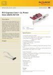
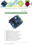
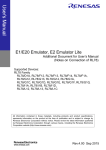
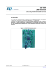
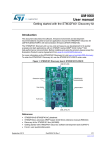
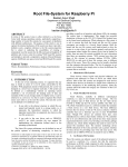
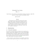
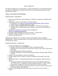
DVK512 User Manual Contents API Demo Code..................................................................................................................................................................................3 Demos................................................................................................................................................................................................. 3 3.2-inch LCD display switch to the HDMI display................................................................................................... 4 HDMI display switch to 3.2-inch LCD display......................................................................................................... 4 LED Demo..................................................................................................................................................................4 8 channel Logic Level Converter Demo.................................................................................................................... 5 74LVC8T245 Level Converter Demo........................................................................................................................5 Joystick demo............................................................................................................................................................. 6 Key Demo...................................................................................................................................................................6 Buzzer and PWM....................................................................................................................................................... 7 DS18B20 Demo..........................................................................................................................................................7 Infrared Remote Control............................................................................................................................................ 8 LCD1602 Demo......................................................................................................................................................... 8 PCF8563 RTC Demo..................................................................................................................................................9 PCF8591 AD/DA Demo...........................................................................................................................................10 Acceleration of Gravity and Magnetic Sensors LSM303DLHC............................................................................. 10 L3G4200D Angle Sensor......................................................................................................................................... 11 Serial Port Demo (the serial port works as console debug output)..........................................................................12 Serial Port Demo (control peripherals via Serial port communication).................................................................. 14 GPS Demo................................................................................................................................................................ 15 API Demo Code All the demo codes for Raspberry Pi and the corresponding Makefile are included in our configured system image: /home/pi/DVK512/. If you're using your own system instead, the demo code can be found here as well: CD_DVK512_EN/Program/ Use the following command to compile the demo code: Make Demos First write the system image we provide to your SD card, enter the system, and double click the "LXTerminal" on the desktop. Log in as root, enter username: su Then the password: raspberry Note: All the demos are running under root account, in case you happen to get stuck or any error occurred, it might be that you're not logging in as root. 3.2-inch LCD display switch to the HDMI display (The default boot mode of the image we provided is booted from 3.2-inch screen, HDMI no output. If you want to output from HDMI, you need to operate as following :) On the LXTerminal, enter HDMI-SYS-SHOW The system will load the driver( wait several minutes), when finished, the raspberry pi will re-boot automatically, after it re-booted, waiting more than 30 seconds, there will be information display on the LCD screen, and enter into startx interface. HDMI display switch to 3.2-inch LCD display Insert the LCD to the Raspberry pi board. On the LXTerminal, enter LCD32-SYS-SHOW The system will load the driver( wait several minutes), when finished, the raspberry pi will re-boot automatically, after it re-booted, waiting more than 30 seconds, there will be information display on the LCD screen, and enter into startx interface. LED Demo On the LXTerminal, enter LED_Test The 8 LEDs should light up one by one. Press "Ctrl+C" to end the demo. 8 channel Logic Level Converter Demo 1, Connect the 8 channel Logic Level Converter to the onboard 8I/Os connector (Note: The VCC1 pinheader on the Logic Level Converter should connect to the 3V3 pinheader of the 8I/Os connector on DVK512); 2, Connect the Logic Level Converter VCC2 to the DVK512 onboard 5V pinheader via DuPont wire; 3. Connect GND to GND; Then open LED JMP jumper, and connect B0-B3 to LED0-LED3 via DuPont wire, open KEY JMP jumper, and connect B4-B7 to KEY0-KEY3 via DuPont wire. On the LXTerminal, enter 8-LOGIC Press KEY0-KEY3 on DVK512, the related LEDs will light up, press “Ctrl+C“ to end the demo. 74LVC8T245 Level Converter Demo 1, Connect the 74LVC8T245 Board to the onboard 8I/Os connector (Note: The VCCA pinheader on the 74LVC8T245 Board should connect to the 3V3 pinheader of the 8I/Os connector on DVK512); 2, Connect the 74LVC8T245 Board VCCB to the DVK512 onboard 5V pinheader via DuPont wire; 3. Connect GND to GND; Then On the LXTerminal, enter 74LVC8T245_Test Open the Jumper Cap in LED JMP, then connect B0-B3 to LED0-LED3, then LEDs will be blinking; then connect B4-B7 to LED0-LED3, then LEDs will be blinking. Press “Ctrl+C” to end the demo Joystick demo (Note: When using the 3.2 inch LCD, the LCD will disturb P0 value read of the joystick, the joystick program will disturb the LCD touch.) Connect the Mix Board to the 8I/Os connector P0-P7, On the LXTerminal, enter JOYSTICK_Test Press any key button or the joystick, LXTerminal will show the one had been pressed. Key Demo (Only for Raspberry Pi Model B+. The system will crash if run on Raspberry Pi Model B) On the LXTerminal, enter KEY_Test Press any key button or the joystick, LXTerminal will show the one had been pressed. Buzzer and PWM Connect the Mix Board to the 8I/Os connector P0-P7, On the LXTerminal, enter, Buzzer_PWM_Test The buzzer will sound with decreasing volume, until no sound. DS18B20 Demo Connect the DS18B20 to Mix Board, and then connect the Mix Board to the onboard 8I/Os connector P0-P7. On the LXTerminal, enter modprobe w1-gpio modprobe w1-therm ls /sys/bus/w1/devices/ You will see a string like 28-000004379b6f, get the last 7 numbers and letters (They are different for each DS18B20, in the writer’s case, it is 4379b6f). Then enter: DS18B20_Test 4379b6f LXTerminal should print the temperature value. Infrared Remote Control Connect the LFN0038K (Infrared Receiver) to the Mix Board IRM connector, connect the Mix Board to the 8I/Os connector P0-P7, On the LXTerminal, enter IRM Press any key on the Infrared Remote Controller provided by Waveshare; The LXTerminal will print the decoded infrared signal in hexadecimal format. Press "Ctrl+C" to end the demo. LCD1602 Demo Connect the "LCD1602" to the LCD1602 connector. On the LXTerminal, enter: LCD1602_Test LCD1602 will display characters. If there is no information, please adjust the potentiometer until there is information displayed. PCF8563 RTC Demo Short the RTC JMP, On the LXTerminal, enter: i2cdetect -y 1 The LXTerminal will print the PCF8563's address, indicating that the PCF8563 has been detected. It's 51 in the writer’s case. The address might be different, depending on the Raspberry Pi's version and the concrete configuration of PCF8563. Then on the LXTerminal, enter: modprobe i2c-dev echo pcf8563 0x51 > /sys/class/i2c-adapter/i2c-1/new_device hwclock –r (for reading the time info from the connected I2C RTC hardware) The LXTerminal will print the time info of the PCF8563, which is different from the system time. Enter: hwclock –w (writing the Raspberry Pi system time info to the PCF8563) Then: hwclock –r Now the time info of Raspberry Pi system and the PCF8563 have been synchronized. hwclock –s (synchronize the system time and the hardware RTC) PCF8591 AD/DA Demo Firstly connect the PCF8591 module we provided to the I2C connector; On the LXTerminal, enter PCF8591-ADC The LXTerminal will print AD Value read from ADC0-ADC3 (pinheader AIN0-ANI3 of PCF8591 module), as the following figure: On the LXTerminal, enter PCF8591-DAC The LXTerminal starts printing digital conversion value; AOUT pinheader of PCF8591 module has a corresponding level variation Acceleration of Gravity and Magnetic Sensors LSM303DLHC Firstly open RTC JMP, exclude interference from RTC. Connect the LSM303DLHC Board to DVK512 onboard I2C connector as figure below: On the LXTerminal, enter: LSM303 Z_A is acceleration in vertical gravity direction, the module will surely to be at equilibrium state as long as the acceleration value of X_A and Y_A is 0; and equilibrium of object can be tested based on this principle North is the value gets from the test. L3G4200D Angle Sensor As the L3G4200D Board needs to use the SPI interface control, but the SPI interface was occupied by 3.2 inch LCD, so to control the L3G4200D Board, it requires to enter HDMI display mode to release the SPI interface occupied by the LCD first. Unplug the 3.2 inch LCD, on the LXTerminal, enter HDMI-SYS-SHOW The system will load the driver (wait several minutes), and release the SPI interface occupied by the LCD, when finished, the raspberry pi will re-boot automatically, after it re-boot, connect the L3G4200D Board to the DVK512 SPI interface, On the LXTerminal, enter su Then enter the password: raspberry Log in as root, and then on the LXTerminal, enter L3G4200D The program running and starts measuring the angular velocity, the greater the velocity, the greater the angular speed. Serial Port Demo (the serial port works as console debug output) The image we provided is used by taking the serial port as a terminal debugging by default; in order to make it convenient for those students who can also control the raspberry pi via serial terminal even they don’t have a screen, firstly connect the DVK512 to the PC via a USB cable, and install a driver. The simplest way is to find a ”Driver Genius Professional" software on the web directly; this software will help you install the driver automatically. Or you can also use the cp2102_Driver. Zip driver under directory "software" in the CD. Short CP_TX and RX, CP_RX and TX of the UART_JMP. Launch putty.exe under directory of “software”, select corresponding COM on”1”, and set Baud rate as 115200 on ”2”, then click “open” on “3”; Then enter the software, connect the raspberry pi to the electricity and start it, the software terminal will display system information, and then appear a pop-up window for you to enter user name and password; User name: pi Password: raspberry Now you can enter the console terminal. Serial Port Demo (control peripherals via Serial port communication) The image we provided is used by taking the serial port as a terminal debugging by default; so the serial port is occupied by the system, which cannot be worked as normal serial port, When using LCD to display, On the LXTerminal, enter: DIS_UART-LCD If use the HDMI output to display, On the LXTerminal, enter: DIS_UART-HDMI The system restarts, disable the serial port to work as terminal debugging output, now it can be used as a normal serial port. Connect the DVK512 to the PC using a mini USB cable, open the serial port monitoring software on another computer, select baud rate as 115200; On the LXTerminal, enter UART_Test A string of words will be printed on the serial port monitoring software, and what you send through the serial port monitoring software, what will be displayed on the serial port monitoring software. Press "Ctrl + C" to end the demo. If you want to turn on the terminal debugging output function of the serial port again, you can re-enter the following command on the terminal: When using LCD to display, On the LXTerminal, enter: EN_UART-LCD when using HDMI output to display, On the LXTerminal, enter: EN_UART-HDMI After entered, the system will reboot and turn on this function. GPS Demo The image we provided is used by taking the serial port as a terminal debugging by default; so to control the peripherals, it needs to disable the debugging function of the serial port first; When using LCD to display, On the LXTerminal, enter: DIS_UART-LCD when using HDMI output to display, On the LXTerminal, enter: DIS_UART-HDMI Then the system will reboot, the disabled serial port will work as terminal debugging output, and can be used as normal serial port. Connect the GPS module to the onboard UART interface and open UART JMP at the same time. On the LXTerminal, enter below to set the baud rate (The baud rate will reset to the default 115200 when the system reboots): stty -F /dev/ttyAMA0 38400 gpsd /dev/ttyAMA0 -F /var/run/gpsd.sock The specific software of the Linux system can be used for GPS positioning; On the LXTerminal, enter cgps -s Below positioning information will be generated: