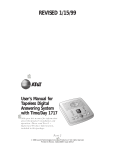
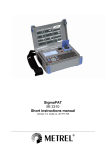
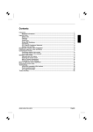
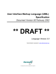
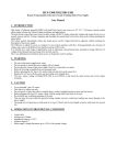
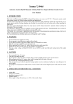
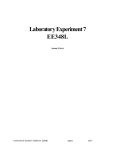
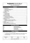
1
US 20040048573A1
(19) United States
(12) Patent Application Publication (10) Pub. No.: US 2004/0048573 A1
(43) Pub. Date:
Clark
(54)
WEATHER RADIO WITH CHANNEL
(57)
Mar. 11, 2004
ABSTRACT
ACQUISITION SYSTEM
(76) Inventor: John M. Clark, Crowley, TX (US)
AWeather radio adapted to automatically select a preferred
channel of operation. A receiver is coupled to a signal
quality circuit that outputs signal quality parameters. A
Correspondence Address:
RADIOSHACK CORPORATION
WILLIAM A. LINNELL COUNSEL
100 THROCKMORTON STREET, SUITE 1700
FORT WORTH, TX 76102 (US)
controller is coupled to control the frequency of reception of
the receiver and is coupled to receive the signal quality
parameters. A memory is used to store several signal quality
values, and is coupled to the controller. When the controller
receives a stimulus, it controls the receiver to sequentially
receive all the Weather radio frequencies of reception and
(21) Appl. No.:
10/236,743
(22) Filed:
Sep. 6, 2002
store a signal quality value for each. The controller subse
quently controls the receiver to receive one of the frequen
cies of operation based upon a comparison of the stored
Publication Classi?cation
values to select a preferred one of them. The radio is
therefore programmed to receive the preferred channel and
(51)
(52)
Int. Cl.7 ........................... .. H04B 15/00; H04B 1/18
US. Cl.
......................................... .. 455/62; 455/1611
monitor NOAA Weather Radio transmissions for the local
FIPS codes and other Weather alert messages.
SELECT DlGlTS FOR FIPS CODE
AND SAVE WHEN COMPLETE
ENTER DEFAULT
CHANNEL
LOAD PLL, READ RSS1, AND
STORE VALUE
SELECT CHANNEL BASED ON
RECEIVED SIGNAL AND SET
AS DEFAULT CHANNEL
Patent Application Publication Mar. 11, 2004 Sheet 1 0f 4
US 2004/0048573 A1
CLAY
UJQAQK
--------- __ _
Fig. l
HENDERSON
Patent Application Publication Mar. 11, 2004 Sheet 2 0f 4
Fig. 2
US 2004/0048573 A1
Patent Application Publication Mar. 11, 2004 Sheet 3 0f 4
US 2004/0048573 A1
36~\
ANTENNA
64\
‘
I66
RECEIVER
‘
RSSI CIRCUIT
A
68\
70\
AUDIO CIRCUITS
v
ANALOG
FSK DECODER
DIGITAL [72
CONVERTER
A
62\
74\ v
LOUDSPEAKER
v
CONTROLLER
‘
I76
<—>
MEMORY
1k
78\
"
USER INTERFACE
LCD DRIVER
AND DISPLAY
I80
Patent Application Publication Mar. 11, 2004 Sheet 4 0f 4
US 2004/0048573 A1
82
—ALL<
ACTIVATE MENU MODE
i
I84
1
as
SELECT LOCTIONS
>/
——>lSELECTED I88
SELECT DIGITS FOR FIPS CODE
AND SAVE WHEN COMPLETE
YES
—(
l
ANOTHER FIPS CODE?
1N0
ACTIVATE MENU MODE
<
CHANNEL SELECT?
—>lAUTO
LOAD PLL, READ RSS1, AND
90
I92
MANUAL
94
/98
STORE VALUE
<
LAST CHANNEL?
lNQ
zYi
100
INCREMENT CHANNEL
|
L102
‘____—
COMPARE RSSI VALUES
1
SELECT CHANNEL BASED ON
RECEIVED SIGNALAND SET
AS DEFAULT CHANNEL
r
TUNE TO DEFAULT CHANNEL
1104
I106
ENTER DEFAULT
CHANNEL
Mar. 11, 2004
US 2004/0048573 A1
WEATHER RADIO WITH CHANNEL
ACQUISITION SYSTEM
BACKGROUND OF THE INVENTION
[0001]
1. Field of the Invention
[0002] The present invention relates to radio communica
tions. More speci?cally, the present invention relates to
radio receivers that operate in conjunction With the National
single source for the most comprehensive Weather and
emergency information available to the public.
[0008]
In recent years, the National Weather Service has
improved the NOAA Weather Radio system to provide
localiZed information and Warning alerts, Which go beyond
the aforementioned radio coverage frequency reuse plan.
The name of this localiZed service is Speci?c Area Message
Encoding
To achieve the localiZed service, the
NWR system broadcasts speci?c SAME codes along With
Oceanic and Atmospheric Administration’s (NOAA)
National Weather Service (NWS) Weather alert broadcasting
system.
the standard Weather broadcasts from its various broadcast
stations. The SAME codes identify the type of emergency
[0003] 2. Description of the Related Art
emergency. Weather alert radios are knoWn in the art that
[0004] NOAA Weather Radio (NWR) is a United States
government service that broadcasts National Weather Ser
emergency might affect them in particular.
and the speci?c geographic area affected by a particular
receive, interpret, and display information about the
received SAME codes so that users can determine if an
vice (NWS) Warnings, Watches, forecasts and other haZard
information tWenty-four hours a day from a netWork of radio
transmitters located throughout the United States. NOAA
[0009]
Each SAME alert includes at least one Federal
Weather Radio is knoWn as the “voice of the National
Information Processing System (FIPS) code that identi?es a
speci?c geographic area, Which is de?ned by the National
Weather Service,” and is provided as a public service by the
Department of Commerce’s National Oceanic and Atmo
Weather Service. It is knoWn in the art to program Weather
radios to receive a particular NWR frequency and to activate
spheric Administration (NOAA).
an alarm consistent With a received SAME code When a
previously programmed FIPS code is received Within a
[0005] The NOAA Weather Radio netWork comprises
SAME message. Thus, the system provides geographic
more than 650 broadcasting stations located in the 50 states
and near adjacent coastal Waters, Puerto Rico, the US.
Virgin Islands and US. Paci?c Territories. The NWS
information about Which users a particular alert message is
directed to, as Well as speci?c information about the nature
of the alert. The FIPS codes are siX-digit numeric codes that
employs medium and loW poWer transmitters deployed
de?ne a geographic region, usually about the siZe of a
typical state county or parish in the US. The ?rst digit in a
according to a frequency reuse plan to provide localiZed
radio coverage Within the network. Radio coverage areas
may be in the range of approximately ?fty miles, although
actual radio coverage areas vary greatly due to the vagaries
of radio Wave propagation. Seven frequencies are set aside
FIPS code generally identi?es the county subdivision, the
neXt tWo digits identify the state, and the last three digits
identify a county or parish. For example, the FIPS code for
Tarrant County, TeXas is “048439”. A listing of all FIPS
in the frequency reuse plan, and, they are tabulated in Table
codes is available from NOAA’s NWS Internet Web site.
1 beloW.
The SAME message alert codes cover a Wide range of
Weather conditions, natural haZards, and technology haZ
TABLE 1
162.400
162.425
162.450
162.475
162.500
162.525
162.550
MHZ
MHZ
MHZ
MHZ
MHZ
MHZ
MHZ
ards. By Way of eXample, these include haZards related to
avalanches, bliZZards, civil emergencies, ?oods, ?res, haZ
ardous materials, high Winds, hurricanes, laW enforcement,
radiological haZards, severe thunderstorms, tornadoes, tsu
namis, volcanoes, Winter storms, and other haZards.
[0010]
In order for a user to bene?t from the NWR alert
broadcast system they must have a compliant radio receiver
properly programmed and in operation to receive and
[0006] Weather radios equipped With a special alarm tone
feature are knoWn in the prior art that can communicate an
alert and provide immediate information about life-threat
ening situations Whenever the alarm tone is received by the
radio. During an emergency, National Weather Service fore
casters interrupt routine Weather radio programming and
send out a special tone that is received by these radios and
used to activate an alarm in Weather radios located Within the
radio coverage area of any given NWR broadcast station.
[0007] Beyond Weather information, the NWR netWork
includes an “all haZards” capability. NOAA Weather Radio
also broadcasts Warning and post-event information for all
types of haZards both natural (such as earthquakes and
volcano activity) and technological (such as chemical
releases or oil spills). In a cooperative effort With other
Federal agencies and the Federal Communications Commis
decode SAME messages, so as to communicate alerts as
they occur from time to time. Programming requires a user
to read and understand the radio’s user manual, and to
operate the radio in such a Way as to program the proper
information into the radio. These operations are naturally
prone to human error from time to time. Since there are
plural FIPS code’s and plural radio frequencies employed by
the NWR broadcast system, it is essential that users program
their radios accurately. For eXample, it is quite common for
a radio receiver located in a particular geographic location to
receive tWo, three, or more NWR broadcast frequencies.
Each of these frequencies may transmit SAME messages
having one, tWo, or more FIPS codes encoded therein. If the
user tunes the radio to the Wrong frequency, they may not
receive their geographic FIPS encoded SAME messages.
Even if the radio has plural FIPS codes programmed therein,
sion’s Emergency Alert System (EAS), NOAA Weather
Which is knoWn in the art, tuning the radio to the Wrong
frequency may still lead to missed SAME messages. Thus
Radio is thus the “all haZards” radio netWork, making it the
there is a need in the art for an apparatus and method that
Mar. 11, 2004
US 2004/0048573 A1
BRIEF DESCRIPTION OF THE DRAWINGS
better ensures that users of NWR compliant radio receivers
are programmed and tuned to the appropriate radio fre
quency, Without the need for extensive manual programming
operations by the user.
SUMMARY OF THE INVENTION
[0011] The need in the art is addressed by the apparatus
and methods of the present invention. A radio is taught that
includes a receiver and a signal quality circuit coupled to the
receiver that has a received signal quality output. A control
ler is coupled to control the frequency of reception of the
receiver and is also coupled to the output. A memory for
storing plural signal quality values is also coupled to the
controller. In operation, upon receipt of a stimulus, the
controller controls the receiver to sequentially receive plural
[0014]
FIG. 1 is a map depicting plural NWS broadcast
transmitters located about a region in Which an illustrative
embodiment Weather radio operates.
[0015] FIG. 2 is a perspective draWing of a Weather radio
according to an illustrative embodiment of the present
invention.
[0016] FIG. 3 is a functional block diagram of a Weather
radio according to an illustrative embodiment of the present
invention.
[0017] FIG. 4 is a radio ?oW diagram according to an
illustrative embodiment of the present invention.
frequencies of reception and store plural signal quality
DESCRIPTION OF THE INVENTION
values, consistent With the signal quality circuit output, in
the memory corresponding to the plural frequencies of
operation. The controller subsequently controls the receiver
tions Will noW be described With reference to the accompa
to receive one of the plural frequencies of operation based
upon a preferred one of the plural signal quality values.
the present invention.
[0012] In a speci?c embodiment, the receiver is a Weather
radio receiver that operates to receive the frequencies of
162.400 MHZ, 162.425 MHZ, 162.450 MHZ, 162.475 MHZ,
162.500 MHZ, 162.525 MHZ, and 162.550 MHZ. In other
embodiments, the signal quality circuit outputs received
signal quality according to received signal strength or the
received signal to noise ratio. The signal quality circuit may
be a received signal strength indicator (R.S.S.I.) circuit. In
another embodiment, the radio further includes an actuator
coupled to the controller, Where activation of the actuator
acts as the stimulus. Or, the controller may execute a
softWare routine that provides the stimulus internally. In
another speci?c embodiment, the radio further includes an
analog to digital converter coupled to receive the received
signal quality output as an analog signal and then digitiZe the
analog signal prior to coupling it to the controller. In another
embodiment, the preferred one of the plural signal quality
values is the one of the plural signal values having the
greatest or least magnitude.
[0013]
In an illustrative embodiment, a Weather radio for
[0018] Illustrative embodiments and exemplary applica
nying draWings to disclose the advantageous teachings of
[0019] While the present invention is described herein
With reference to illustrative embodiments for particular
applications, it should be understood that the invention is not
limited thereto. Those having ordinary skill in the art and
access to the teachings provided herein Will recogniZe
additional modi?cations, applications, and embodiments
Within the scope thereof and additional ?elds in Which the
present invention Would be of signi?cant utility.
[0020]
FIG. 1 is a map 2 of a portion of North Texas in the
area of Dallas and Fort Worth, Which are located in Dallas
County and Tarrant County respectively. An illustrative
embodiment Weather radio 1 is located in the northWest
quadrant of Dallas County. The map 2 and Weather radio 1
Will be used to describe both the problem in the prior art and
the advantages of the present invention With respect to the
operation of Weather radios in areas receiving multiple
NWR broadcast coverage. Multiple NWR transmitters serve
North Texas. In the geographic area depicted in map 2, there
are six NWR broadcast transmitters, Which are listed in
Table 2 beloW.
receiving signals from the NOAA Weather Radio broadcast
systems is taught. The Weather radio includes a receiver
selectively tunable to receive plural frequencies in the
NOAA Weather Radio band, currently including 162.400
MHZ, 162.425 MHZ, 162.450 MHZ, 162.475 MHZ, 162.500
MHZ, 162.525 MHZ, and 162.550 MHZ. An R.S.S.I. signal
TABLE 2
Station
Ref. No.
Coverage County
Frequency
Call Sign
Dallas
12
14
Dallas
Cumby
28
30
Hopkins
162.500 MHZ KWN31
is coupled to the output and operates to convert the analog
Corsicana
Dublin
Fort
Worth
24
20
8
26
22
10
Navarro
Erath
Johnson
162.525 MHZ KXI67
162.450 MHZ KWN33
162.550 MHZ KEC55
received signal quality to a digital signal, suitable for digital
Sherman
16
18
Grayson
162.475 MHZ WXK22
quality circuit is coupled to the receiver and has an analog
received signal quality output. A digital to analog converter
162.400 MHZ KEC56
manipulation. A controller is coupled to control the fre
quency of reception of the receiver and is also coupled to
receive the digital signal. A memory for storing plural signal
[0021]
quality values is coupled to the controller as Well. The
controller, upon receipt of a stimulus, controls the receiver
station is approximated by a corresponding broken line.
to sequentially receive the plural frequencies of reception
and store plural signal quality values, consistent With the
digital signal, in the memory corresponding to the plural
frequencies of operation. Also, the controller subsequently
The radio coverage area of each NWR broadcast
With respect to Table 2, the “Ref. No.” column lists the
draWing reference numeral associated With each NWR
broadcast station and the “Coverage” column lists the draW
ing reference numeral associated With each corresponding
coverage area broken line. Those skilled in the art Will
appreciate that the vagaries of radio Wave propagation never
controls the receiver to receive one of the plural frequencies
of operation based upon a preferred one of the plural signal
quality values that is selected as having the greatest or least
de?ne a simple circular area as an actual area of radio
magnitude.
receiver sensitivity, antenna gain and elevation, and many
coverage. Rather, local terrain, vegetation, elevation,
Mar. 11, 2004
US 2004/0048573 A1
other factors de?ne a much more complex coverage map for
each transmitter. HoWever, the problem existing in the prior
art is clearly illustrated using the simple circular approxi
mation for radio coverage area. Note that the illustrative
embodiment Weather radio receiver 1 falls Within the radio
coverage area approximated for the Dallas station 12, the
Forth Worth station 8, and the Sherman station 16, having
radio coverage areas 14, 10, and 18 respectively. Prior art
Weather radios Were either manually tuned to one station,
Which is prone to selection error, or automatically tuned in
a simple sequential scan of the seven frequencies (see Table
1). In a sequential scan, the ?rst station having adequate
signal strength to quiet the receiver is selected as the default
frequency of reception. Thus, there is a signi?cant probabil
ity that a given Weather radio receiver 1 Will not be tuned to
the NWR broadcast station that is designated for the user’s
county, or other geographic subdivision de?ned by the
SAME FIPS code system. In FIG. 1, the Weather radio 1 lies
Within Dallas County and therefore is preferably tuned to the
Dallas NWR station 12. HoWever, user programming error
or a sequential tuning process may actually result in the
radio 1 being tuned to the Fort Worth station 8 or the
Sherman station 16, or perhaps some other station that
propagates a signal of suf?cient strength at location 1. This
results in the user not receiving the best Weather informa
tion, and, depending of the FIPS alert message encoding
employed at the various NWR stations, may result in com
pletely missing critical NOAA alerts.
[0022] The present invention overcomes the problems in
the prior art by employing circuitry and softWare that scans
all of the NWR broadcast frequencies, detecting the quality
of each received radio signal. Values associated With each
received signal’s quality are stored in a memory and then a
comparative process is employed to select the one of the
plural received signals that is most likely to be the local
county broadcast station signal. When this is combined With
the user programmed FIPS code, or code’s, the net result is
an improvement in the likelihood that a given user Will
receive the preferred NWR broadcast station and have the
proper FIPS code programmed.
[0023] Reference is directed to FIG. 2, Which is a per
spective draWing of a Weather radio 34 according to an
illustrative embodiment of the present invention. The
Weather radio is enclosed in a molded case, Which supports
the internal circuitry (not shoWn) and various user interface
and external functional components. A loudspeaker grill 62
alloWs sound to propagate from an internal loudspeaker (not
shoWn). A telescopic antenna 36 intercepts radio signals
broadcast from NWR broadcast stations. A“Weather” actua
tor 56 causes the radio to receive and reproduce NWR audio
broadcasts from a presently tuned default frequency With a
single actuation by a user. A “Menu” actuator 40 and four
directional actuators 42, 44, 46, and 48 provide user access
to a function menu interface that operates in conjunction
With a liquid crystal display 38. The display 38 is capable of
reproducing alpha-numeric textual messages that appear in
[0024] The display 38 is also used to display alert mes
sages and various programming data, such as FIPS codes,
broadcast frequencies, and other parameters. In addition to
textual information output, the Weather radio 34 can also
route alert tones to the loudspeaker for an audio indication.
Three dedicated alert indicator lamps, or LED’s, are also
provided. These include a “Statement” indicator 50, a
“Watch” indicator 52, and a “Warning” indicator 54. The
three alert levels re?ect the alert levels de?ned by the NWS
that are encoded into certain SAME alert messages. When a
SAME alert message having a FIPS code programmed into
the Weather radio 34 is broadcast on the presently received
frequency of the radio, the radio decodes the SAME mes
sage and outputs and alert consistent With the level of alert
decoded from the message. The appropriate indicator lamp
50, 52 or 54 is then illuminated to notify the user. The
illustrative embodiment radio also includes a data interface
60 that alloWs interconnection of the device to a personal
computer. Also, the back 58 of the radio 34 includes a DC
poWer input connector (not shoWn), an alert on/off sWitch
(not shoWn) and an alarm output connector (not shoWn).
Such connections are knoWn in the art and used in prior art
Weather radio designs.
[0025] Reference is directed to FIG. 3, Which is a func
tional block diagram of a Weather radio according to an
illustrative embodiment of the present invention. Radio
signals transmitted from a NWR broadcast station are
received by antenna 36, Which may be an internal antenna or
an externally connected antenna. The received signals are
coupled to a conventional VHF radio receiver 64 that is
selectively tunable to the seven NWS radio frequencies. In
the illustrative embodiment, a phase-locked-loop circuit is
used that employs a stable reference oscillator such that the
controller 74 is able to selectively tune the receiver 64 to any
of the seven NWS broadcast frequencies. Those skilled in
the art Will appreciate that other selectively tunable receiver
circuit topologies could readily be employed. A signal
quality circuit 66 is coupled to the receiver 64 and outputs
a signal indicative of the received signal quality. In the
illustrative embodiment, a received signal strength indica
tion circuit 66, knoWn to those skilled in the art as an R.S.S.I.
circuit, is employed. The R.S.S.I. circuit 66 outputs an
analog signal Whose magnitude is proportional to the
received signal strength. Other signal quality circuits knoWn
to those skilled in the art can also be employed as Well. For
example, a signal-to-noise circuit or a carrier-to-noise circuit
could be used. The signal quality circuit 66 may also employ
integration techniques so that the received signal quality can
be averaged over time. In the illustrative embodiment, the
analog signal output from R.S.S.I. circuit 66 is coupled to an
analog to digital converter 72 Where the analog signal is
sampled and digitiZed for later manipulation by controller
74. The demodulated received signal is output from the
receiver 64 to both a frequency shift keying (FSK) decoder
circuit 70 and to audio conditioning circuits 68.
[0026] The FSK decoder circuit 70 receives the base-band
demodulated signal from the receiver 64 and decodes the
FSK-encoded SAME messages, Which are FSK-modulated
response to user actuation of the aforementioned actuators
Within the base-band signal, as is knoWn to those skilled in
40, 42, 44, 46, and 48. Those skilled in the art are familiar
With menu driven user interface, and the general advantages
of such systems. The menu interface alloWs a large number
of features and functions to be logically organiZed and
accessible With a relatively small number of input actuators.
the art. The content of SAME messages are knoWn to those
skilled in the art and speci?cations for them are available
from NOAA and the National Weather Service. Essentially,
SAME messages include certain Warning codes and FIPS
codes. Once the SAME messages are decoded by FSK
Mar. 11, 2004
US 2004/0048573 A1
decoder 70, the contents of the SAME messages are coupled
to controller 74 Where they are interpreted, stored in memory
76, and acted upon as required from message to message,
and according to the radio programming. For example, a
SAME message might include a tornado Warning code With
a FIPS code for a particular county. AWeather radio that is
tuned to the particular broadcast, and that has the particular
FIPS code programmed for reception, Will activate a tornado
Warning in response to the received message. The base-band
received signal output from receiver 64 is also coupled to
audio conditioning circuits 68. A digital volume control is
included Within the audio circuits 68 and is controlled by
controller 74. Radio volume selection is a function of the
aforementioned menu driven user interface. When the user
desires to adjust the speaker volume of the received audio
signal, or the speaker volume of the alarm tones, the
appropriate menu selection is activated and up-doWn actua
tors are manipulated to achieve the desired volume adjust
ment. Tone generating and ?ltering circuits are also included
in audio circuits 68 so that the needed tones can be produced
and controlled by controller 74. Ultimately, the received
audio signals are coupled to loudspeaker 62 for listening by
a user.
[0027] Referring again to the analog to digital circuit 72,
this circuit outputs a digitiZed version of the signal quality
information received from the signal quality circuit 66,
Which is an R.S.S.I. circuit in the illustrative embodiment.
The digitiZed output from the analog to digital converter 72
is coupled to controller 74. The digitiZed information is
associated With the particular radio frequency being received
at the time the controller 74 reads the information and the
value is stored in memory 76 for later recollection and
analyses by controller 74. Controller 74 may be of any of the
menu mode of operation is activated. This is the aforemen
tioned menu interface of the illustrative embodiment
Weather radio. The user selects the mode of entry for FIPS
location codes as either ALL locations or speci?cally
SELECTED locations at step 86. If ALL locations are
chosen at step 86, then the radio Will respond to all of the
Weather alerts that it receives. Thus, no speci?c FIPS loca
tion codes need to be entered and How proceeds immediately
to step 92, discussed hereinafter. On the other hand, at step
86, if the user chooses to SELECT speci?c FIPS location
codes, then ?oW proceeds to step 88 Where the user enters
the required digits for the desired FIPS location code. The
required digits are available from printed literature as Well as
the NOAA NWS Internet Web site. As each code is entered
(and there may be just a single code) the user is queried at
step 90 to determine if another FIPS location code is to be
entered. If YES, ?oW returns to step 88 to alloW entry of
another FIPS location code. If NO additional codes are
desired by the user at step 90, then ?oW proceeds to step 92.
[0030]
Having entered the desired FIPS location codes at
steps 88 and 90, the process returns to an idle state until the
user again activates the menu mode at step 92 to initiate the
channel selection process. This is the process through Which
the radio determines What radio frequency, or channel, to
monitor as the local default channel. The user is queried to
choose manual or automatic channel selection at step 94. If
the user selects the MANUAL mode of channel selection,
then the user enters this information at step 96 and the
process proceeds to step 108, discussed hereinafter. On the
other hand, at step 94, if the user selects the AUTO mode of
default channel selection, then ?oW proceeds to step 98. Step
98 is the beginning of an automated iterative process that
scans all seven NOAA NWR channels and checks for signal
types knoWn and used in dedicated control applications,
quality. This is accomplished by loading the ?rst channel at
including processor, microprocessors, controllers, micro
controllers, digital signal processors and other program
step 98. In the illustrative embodiment, the channel is
mable control devices. Amemory 76 is provided for storing
signal quality information, FIPS codes, SAME messages
and alerts, executable softWare, variable, and other infor
mation that needs to be stored or recalled by controller 74
from time to time. The various functions depicted in FIG. 3
may be combined depending on the level of circuit integra
tion employed by the designer of a product.
[0028] Continuing in FIG. 3, the controller 74 is coupled
to a user interface 78, Which includes the various push
button actuators, sWitch actuators and indicator lamps
described elseWhere. In the illustrative embodiment, the key
actuators are arranged in a key matrix that is scanned by
controller 74 for detection of actuation events by a user. The
executable softWare running on controller 74 is responsive
to key actuation events and embodies the user interface
functionality of the Weather radio. An LCD driver and LCD
display 80 are also employed in the illustrative embodiment
Weather radio. The LCD display 80 is an alpha-numeric type
and serves to present menu options to the users, as Well as
communicate alerts and other operational information. Cer
tain icons are also included in the display 80 for convenient
indication of operational events. Use and implementation of
LCD displays are Well knoWn to those skilled in the art.
[0029] Reference is directed to FIG. 4, Which is a How
diagram of the radio channel selection process according to
an illustrative embodiment of the present invention. The
process starts at step 82 and proceeds to step 84 Where the
de?ned by loading the phase locked loop With the proper
channel divisor, Which tunes the receiver, and then reading
the signal quality, Which is the R.S.S.I. value. This value is
stored in the memory at a location associated With the
present radio channel. Then ?oW proceeds to step 100. Step
100 is a test to determine if the last of the seven channels has
been loaded and measured. If not, How continues to step 102
Where the channel divisor is incremented and then returns
back to step 98 to load and measure the next channel. Once
all of the channels have been measured and the associated
signal quality value stored, the last channel test is successful
at step 100 and How proceeds to step 104.
[0031] At step 104, the controller compares the stored
R.S.S.I. values. At step 106, the best channel, meaning the
channel With the strongest received signal, is selected and
de?ned as the default radio channel. This is the speci?c
embodiment of the illustrative embodiment Weather radio.
In the case Where the signal quality parameter is different,
such as signal to noise ratio, then the channel selection
algorithm is adapted accordingly. The essential process is to
check the signal quality of all the channels, and then select
the preferred one of the plural channels as the default
channel. Having selected a default channel, ?oW continues
to step 108 Where the radio is tuned to the default channel
for subsequent operation. The process returns at step 110.
[0032] Thus, the present invention has been described
herein With reference to particular embodiments for particu
lar applications. Those having ordinary skill in the art and
Mar. 11, 2004
US 2004/0048573 A1
access to the present teachings Will recognize additional
modi?cations, applications and embodiments Within the
scope thereof.
[0033]
It is therefore intended by the appended claims to
cover any and all such applications, modi?cations and
embodiments Within the scope of the present invention.
What is claimed is:
1. A radio, comprising:
a receiver;
a signal quality circuit, coupled to said receiver, having a
received signal quality output;
a controller coupled to control the frequency of reception
of said receiver and coupled to said output;
a memory for storing plural signal quality values coupled
to said controller, and Wherein
said controller, upon receipt of a stimulus, controls said
receiver to sequentially receive plural frequencies of
reception and store plural signal quality values, con
sistent With said signal quality circuit output, in said
memory corresponding to said plural frequencies of
operation, and Wherein
said controller subsequently controls said receiver to
receive one of said plural frequencies of operation
based upon a preferred one of said plural signal quality
values.
2. The apparatus of claim 1 Wherein said receiver is a
Weather radio receiver.
3. The apparatus of claim 2 Wherein said Weather radio
receiver is operable to receive frequencies in the NOAA
Weather Radio band.
4. The apparatus of claim 1 Wherein said signal quality
circuit outputs received signal quality according to received
a received signal strength indication (R.S.S.I.) signal
quality circuit, coupled to said receiver, having an
analog received signal quality output;
a digital to analog converter coupled to said output and
operable to convert said analog received signal quality
to a digital signal;
a controller coupled to control the frequency of reception
of said receiver and coupled to receive said digital
signal;
a memory for storing plural signal quality values coupled
to said controller, and Wherein
said controller, upon receipt of a stimulus, controls said
receiver to sequentially receive said plural frequencies
of reception and store plural signal quality values,
consistent With said digital signal, in said memory
corresponding to said plural frequencies of operation,
and Wherein
said controller subsequently controls said receiver to
receive one of said plural frequencies of operation
based upon a preferred one of said plural signal quality
values that is selected as having the greatest or least
magnitude.
12. Amethod of selecting a preferred frequency of recep
tion in a radio having a receiver, comprising the steps of:
sequentially tuning the receiver to receive plural frequen
cies of reception;
determining plural signal quality values corresponding to
said plural frequencies of reception;
selecting a preferred one of said plural frequencies of
signal strength.
reception based upon said plural signal quality values,
5. The apparatus of claim 1 Wherein said signal quality
circuit outputs received signal quality according to the
received signal to noise ratio.
6. The apparatus of claim 1 Wherein said signal quality
circuit is a received signal strength indication (R.S.S.I.)
and
circuit.
7. The apparatus of claim 1, further comprising:
an actuator coupled to said controller, and
Wherein activation of said actuator acts as said stimulus.
8. The apparatus of claim 1 Wherein said controller
eXecutes a softWare routine that provides said stimulus.
tuning the receiver to said preferred one of said plural
frequencies of reception.
13. The method of claim 12 Wherein said receiver is a
Weather radio receiver.
14. The method of claim 13 Wherein said plural frequen
cies of reception are in the NOAA Weather Radio band.
15. The method of claim 12 Wherein said determining step
is accomplished With a signal quality circuit in the radio that
outputs a received signal quality according to received
9. The apparatus of claim 1, further comprising:
signal strength.
an analog to digital converter coupled to receive said
16. The method of claim 12 Wherein said determining step
is accomplished With a signal quality circuit in the radio that
received signal quality output as an analog signal and
digitiZe said analog signal prior to coupling to said
controller.
10. The apparatus of claim 1 Wherein said preferred one
of said plural signal quality values is the one of said plural
signal values having the greatest or least magnitude.
11. AWeather radio for receiving signals from the NOAA
Weather Radio broadcast systems, comprising:
a receiver selectively tunable to receive plural frequen
cies, including 162.400 MHZ, 162.425 MHZ, 162.450
MHZ, 162.475 MHZ, 162.500 MHZ, 162.525 MHZ, and
162.550 MHZ;
outputs received signal quality according to the received
signal to noise ratio.
17. The method of claim 12 Wherein said determining step
is accomplished by a received signal strength indication
(R.S.S.I.) circuit in the radio.
18. The method of claim 12, Wherein the radio includes an
actuator, further comprising the steps of:
actuating the actuator, and
executing said sequentially tuning step in response to said
actuating step.
Mar. 11, 2004
US 2004/0048573 A1
19. The method of claim 12 wherein the radio has a
controller that executes a software routine, and Wherein said
sequentially tuning step occurs automatically Within the
softWare routine.
20. The method of claim 12 Wherein said selecting step
selects said preferred one of said plural signal quality values
as the one of said plural signal values having the greatest or
least magnitude.
21. The method of claim 12 Wherein the radio has a
memory, further comprising the step of:
storing said plural signal values in the memory.
*
*
*
*
*