1
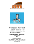
Production Screen Tester
Part No. 810-00-1
Instruction Manual
Updated 3/10/2014
Ver. 1.0
OFI Testing Equipment, Inc.
11302 Steeplecrest Dr. · Houston, Texas · 77065 · U.S.A.
Tele: 832.320.7300 · Fax: 713.880.9886 · www.ofite.com
Copyright OFITE 2015
©
Table of
Contents
Intro..................................................................................................2
Description.......................................................................................2
Specifications..................................................................................2
Components....................................................................................3
Safety................................................................................................4
Quick Start.......................................................................................5
Operation.........................................................................................6
Diagram.......................................................................................... 11
Cell Assembly............................................................................ 11
Advanced Screen Holder Assembly...........................................12
Appendix........................................................................................13
Advanced Screen Holder Assembly...........................................13
Cap Screen Assembly................................................................14
Warranty and Return Policy.........................................................15
OFITE, 11302 Steeplecrest Dr., Houston, TX 77065 USA / Tel: 832-320-7300 / Fax: 713-880-9886 / www.ofite.com
1
Intro
The flow-back characteristics of drill-in fluids are critical to the productivity
of a well. If the fluid plugs the production screen, it will not only slow down
production, but it could also lead to screen erosion and costly remediation.
The PST is designed to test flow-back of completion fluids on the rig site. It
is no longer necessary to ship fluid samples back to the lab and delay the
completion operation for days or weeks. Field fluids can be tested in real time
with samples of the actual production screen being used down hole.
The PST now makes it possible to determine if the fluid remaining in the
annulus will flow back through the production screen.
Description
Specifications
The Production Screen Tester is similar to the standard API filter press both
in appearance and operation. The user assembles a test cell with a sample of
the production screen at the bottom. After filling the cell with fluid, he applies
pressure and opens a valve at the bottom. The test will very quickly show
whether the screen and fluid are compatible, or if plugging is a possibility. And
the apparatus is simple enough that new screen samples can be installed
and tested quickly and easily.
Pressure Source: CO2
Cell Size: 3" (7.8) ID × 10.9" (27.6 cm) Long
Sample Volume: 1,000 mL
Screen Size: 1.9" (50 mm) Diameter and 2.5" (63.5 mm) Diameter
Size: 11.5" × 8" × 27" (29 × 20 × 69 cm)
Weight: 24 lb (10.9 kg)
OFITE, 11302 Steeplecrest Dr., Houston, TX 77065 USA / Tel: 832-320-7300 / Fax: 713-880-9886 / www.ofite.com
2
Components
#120-60-30
#141-05
#141-06
#141-09
#141-10
#141-22
#142-00
#153-78
#170-13
#810-00-002
#810-00-003
#810-00-005
#810-00-006
#810-00-007
#810-00-020
#810-00-021
#810-00-022
LP SS Tubing, 2" × ¼"
Neoprene Gasket; Qty. 2
Cell Pin; Qty. 2
Threaded Insert W/Set Screw
T-screw
Felt Filter
CO2 Pressuring Assembly With Top Cap
¼" Polyurethane (Flex) Tubing
O-ring Nitrile
Bottom Cap Assembly
Cell Body
O-ring Nitrile
Cap Screen
Bottom Cup Insert
Plastic Main Insert
Thick Spacer Ring
Thin Spacer Ring; Qty. 2
Optional:
#810-00-010
#810-00-010A
#810-00-010B
#810-00-010C
#810-00-010D
#810-00-020-1
Advanced Screen Holder Assembly
Advanced Screen Holder
Thick Spacer
Thin Spacer; Qty. 2
Locking Ring
Screen Tester Main Insert (SS 303)
Tools:
#120-50-076
#120-58-07
#170-27
9/16" Combination wrench; Qty. 2
5/64"Allen wrench for Threaded Insert for T-Screw
5/32" Allen wrench for Base Cap Set Screws
OFITE, 11302 Steeplecrest Dr., Houston, TX 77065 USA / Tel: 832-320-7300 / Fax: 713-880-9886 / www.ofite.com
3
Safety
Carbon Dioxide gas is normally supplied in small bulbs or cartridges, which
contain approximately 900 PSI (6,206 kPa) pressure when new. Because
they are highly portable, they are usually used in field operations. These
bulbs should not be exposed to high heat (50°C/120°F) as they can explode if
over heated.
Never transport CO2 bulbs or cartridges by airplane without proper packaging.
Cabin depressurization could cause them to explode.
OFITE, 11302 Steeplecrest Dr., Houston, TX 77065 USA / Tel: 832-320-7300 / Fax: 713-880-9886 / www.ofite.com
4
Quick Start
1. Measure the initial fluid temperature.
2. Assemble the test cell.
3. Pour the fluid into the test cell.
4. Place the top cap on the cell body.
5. Place the cell into the frame and secure it with the T-screw.
6. Apply pressure and start the timer.
7. Record temperature, time, and fluid volume.
8. Release the pressure.
9. Disassemble the cell and clean all components.
OFITE, 11302 Steeplecrest Dr., Houston, TX 77065 USA / Tel: 832-320-7300 / Fax: 713-880-9886 / www.ofite.com
5
Operation
1. Before beginning a test, make sure each part of the cell is clean and dry,
particularly the screen. Examine the gaskets for distortion and wear. Make
sure the screen is free of sharp edges, burrs, or tears.
2. Measure the initial temperature of the fluid sample and record it for later
analysis.
3. Assemble the test cell (to assemble the cap screens see 13 and 14):
a. Assemble the Bottom Cap.
i. Place a gasket in the inside groove in the bottom cap.
Bottom Cap with Gasket
ii. Apply lubrication to the inner bottom cap (#810-00-007) and place
an o-ring (#170-13) in the designated seat.
Bottom Cup Insert
Bottom Cup Insert with O-ring
iii. Place the bottom cup insert into the bottom cap. Screw the fitting
(#130-78-045) into the bottom of the bottom cup insert.
¼" NPT Fitting,
(#130-78-045)
Bottom Cup
Insert,
(#810-00-007)
Bottom Cap,
(#810-00-002)
Bottom Cup
Insert,
(#810-00-007)
OFITE, 11302 Steeplecrest Dr., Houston, TX 77065 USA / Tel: 832-320-7300 / Fax: 713-880-9886 / www.ofite.com
6
Shut Off Valve Assembly Installation
iv. Use two 9/16" wrenches to install the Shut Off Valve Assembly
(#120-910-070) to the NPT connector on the inner cap as shown
above.
b. Assemble the Main Insert (Plastic) (#810-00-020).
i. Insert an o-ring (#170-13) into the internal portion of the insert and
lubricate the o-ring as shown below (left).
ii. Install the external o-ring (#810-00-005) and lubricate the external
portion of the insert as shown below (right).
Internal O-ring
External O-ring
OFITE, 11302 Steeplecrest Dr., Houston, TX 77065 USA / Tel: 832-320-7300 / Fax: 713-880-9886 / www.ofite.com
7
iii. Place the Insert into the bottom side of the cell and press down to
sit flush inside the cell.
c. Assemble the cap screen.
i. Insert spacers and screens as needed.
ii. Place an o-ring (#810-00-004) into the plastic insert.
iii. Insert the cap screen (#810-00-006) as shown below.
i. Spacer Insert
ii. O-ring Insert
iii. Cap Screen Insert
Cap Screen Installed
OFITE, 11302 Steeplecrest Dr., Houston, TX 77065 USA / Tel: 832-320-7300 / Fax: 713-880-9886 / www.ofite.com
8
d. Place the assembled bottom cap onto the cell and turn it to lock it into
place. Use a 5/32" allen wrench to tighten the set screws which secure
the cell cap to the cell.
e. Turn the cell assembly right side up.
4. Pour the freshly stirred sample fluid into the cell, leaving 0.5" (13 mm) of
empty space at the top.
OFITE, 11302 Steeplecrest Dr., Houston, TX 77065 USA / Tel: 832-320-7300 / Fax: 713-880-9886 / www.ofite.com
9
5. Place a rubber gasket inside the top cap. Make sure it is seated all the
way around the cap. Then place the top cap onto the top of the cell body.
6. Place the entire cell into the frame and secure the cell with the T-screw.
Top Cap with Gasket
7. Place a clean, dry 1,000 mL Beaker under the filtrate tube.
8. With the regulator closed and the relief valve pushed in, place a CO2
bulb into the sleeve and screw it onto the pressure assembly. This will
puncture the bulb and release the pressure.
9. Turn the regulator T-screw clockwise to adjust the pressure. Start the
timer.
10.At the end of the test, back off the regulator and record the following:
a. If the fluid plugs the screen, record the time and the volume of fluid
collected.
b. If the fluid does not plug the screen, record the time required for all
the fluid to flow through the screen.
11.Pull the relief valve out to release any remaining pressure.
12.Remove the cell from the frame and disassemble it. Discard any
remaining fluid.
13.After each test, disassemble the test cell and thoroughly clean all
surfaces with soap and water. Make sure all parts are clean and dry
before storing the unit.
OFITE, 11302 Steeplecrest Dr., Houston, TX 77065 USA / Tel: 832-320-7300 / Fax: 713-880-9886 / www.ofite.com
10
Diagram
Cell Assembly
CO2 Pressuring
Assembly
With Top Cap
(#142-00)
Cell Body
(#810-00-003)
Cell Pin (Qty. 2)
(#141-06)
O-ring, Nitrile
(#810-00-004)
Cap Screen
(#810-00-006)
O-ring, Nitrile
(#810-00-005)
Main Insert (Plastic)
(#810-00-020)
O-ring, Nitrile
(#170-13)
Thin Spacer
(#810-00-021)
O-ring, Nitrile
(#170-13)
Bottom Cup Insert
(#810-00-007)
Thin Spacer
(#810-00-022)
O-ring, Nitrile
(#170-13)
Gasket, Neoprene
(#141-05)
Bottom Cap Assembly
(#810-00-002)
Fitting, Male Connector,
¼" (#130-78-045)
LP SS Tubing, 2" × ¼"
(#120-60-30)
Shut Off Valve ¼"
(#120-910-070)
¼" Polyurethane Tubing
(#153-78)
OFITE, 11302 Steeplecrest Dr., Houston, TX 77065 USA / Tel: 832-320-7300 / Fax: 713-880-9886 / www.ofite.com
11
Diagram
Advanced Screen
Holder Assembly
(Optional)
Locking Ring,
(#810-00-010D)
O-ring
(#810-00-004)
Thick Spacer
(#810-00-010B)
Thin Spacer
(#810-00-010C)
Screen Holder,
Advanced
(#810-00-010A)
OFITE, 11302 Steeplecrest Dr., Houston, TX 77065 USA / Tel: 832-320-7300 / Fax: 713-880-9886 / www.ofite.com
12
Appendix
Advanced Screen
Holder Assembly
(Optional)
The Advanced Screen Holder (#810-00-010) is an optional screen assembly
which includes spacers to accommodate multiple screens of varying
thickness up to ½" and 50 mm in diameter. Not all screens will require the
use of every spacer. The thickness of screens can be different which may
eliminate the use of other spacers.
Screen Holder,
Advanced
(#810-00-010A)
Thick Spacer
(#810-00-010B)
Thin Spacer
(#810-00-010C)
Locking Ring,
(#810-00-010D)
Advanced Screen Holder Assembly (#810-00-010)
1. Place spacers as needed into holder assembly.
2. Place screen into screen holder and more spacers if needed.
3. Place an o-ring (#810-00-004) into screen holder.
4. Secure screen assembly with Locking Ring (#810-00-010D)
5. Place assembled screen holder into insert.
OFITE, 11302 Steeplecrest Dr., Houston, TX 77065 USA / Tel: 832-320-7300 / Fax: 713-880-9886 / www.ofite.com
13
Appendix
Cap Screen Assembly
The Cap Screen Assembly is an optional screen assembly which includes
spacers to accommodate multiple screens of varying thickness up to ⅜" and
2.5" in diameter. Not all screens will require the use of every spacer. The
thickness of screens can be different which may eliminate the use of other
spacers.
Cap Screen
(#810-00-006)
Thin Spacer (Qty. 2)
(#810-00-022)
Thick Spacer
(#810-00-021)
Cap Screen Assembly
1. Place spacers as needed into holder assembly.
2. Place screen into screen holder and more spacers if needed.
3. Place an o-ring (#810-00-004) into screen holder.
4. Place assembled screen holder into insert.
OFITE, 11302 Steeplecrest Dr., Houston, TX 77065 USA / Tel: 832-320-7300 / Fax: 713-880-9886 / www.ofite.com
14
Warranty and
Return Policy
Warranty:
OFI Testing Equipment, Inc. (OFITE) warrants that the products shall be free from liens and defects in
title, and shall conform in all respects to the terms of the sales order and the specifications applicable
to the products. All products shall be furnished subject to OFITE’s standard manufacturing variations
and practices. Unless the warranty period is otherwise extended in writing, the following warranty shall
apply: if, at any time prior to twelve (12) months from the date of invoice, the products, or any part
thereof, do not conform to these warranties or to the specifications applicable thereto, and OFITE is
so notified in writing upon discovery, OFITE shall promptly repair or replace the defective products.
Notwithstanding the foregoing, OFITE’s warranty obligations shall not extend to any use by the buyer
of the products in conditions more severe than OFITE’s recommendations, nor to any defects which
were visually observable by the buyer but which are not promptly brought to OFITE’s attention.
In the event that the buyer has purchased installation and commissioning services on
applicable products, the above warranty shall extend for an additional period of twelve
(12) months from the date of the original warranty expiration for such products.
In the event that OFITE is requested to provide customized research and development for the buyer,
OFITE shall use its best efforts but makes no guarantees to the buyer that any products will be provided.
OFITE makes no other warranties or guarantees to the buyer, either express or implied,
and the warranties provided in this clause shall be exclusive of any other warranties
including ANY IMPLIED OR STATUTORY WARRANTIES OF FITNESS FOR PURPOSE,
MERCHANTABILITY, AND OTHER STATUTORY REMEDIES WHICH ARE WAIVED.
This limited warranty does not cover any losses or damages that occur as a result of:
•
Improper installation or maintenance of the products
•
Misuse
•
Neglect
•
Adjustment by non-authorized sources
•
Improper environment
•
Excessive or inadequate heating or air conditioning or electrical
power failures, surges, or other irregularities
•
Equipment, products, or material not manufactured by OFITE
•
Firmware or hardware that have been modified or altered by a third party
•
Consumable parts (bearings, accessories, etc.)
Returns and Repairs:
Items being returned must be carefully packaged to prevent damage in
shipment and insured against possible damage or loss. OFITE will not be
responsible for equipment damaged due to insufficient packaging.
Any non-defective items returned to OFITE within ninety (90) days of invoice are subject to a
15% restocking fee. Items returned must be received by OFITE in original condition for it to
be accepted. Reagents and special order items will not be accepted for return or refund.
OFITE employs experienced personnel to service and repair equipment manufactured by us, as
well as other companies. To help expedite the repair process, please include a repair form with all
equipment sent to OFITE for repair. Be sure to include your name, company name, phone number,
email address, detailed description of work to be done, purchase order number, and a shipping address
for returning the equipment. All repairs performed as “repair as needed” are subject to the ninety (90)
day limited warranty. All “Certified Repairs” are subject to the twelve (12) month limited warranty.
Returns and potential warranty repairs require a Return Material Authorization (RMA)
number. An RMA form is available from your sales or service representative.
Please ship all equipment (with the RMA number for returns or warranty repairs) to the following address:
OFI Testing Equipment, Inc.
Attn: Repair Department
11302 Steeplecrest Dr.
Houston, TX 77065
USA
OFITE also offers competitive service contracts for repairing and/or maintaining your lab
equipment, including equipment from other manufacturers. For more information about
our technical support and repair services, please contact [email protected].
OFITE, 11302 Steeplecrest Dr., Houston, TX 77065 USA / Tel: 832-320-7300 / Fax: 713-880-9886 / www.ofite.com
15