1
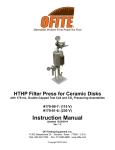
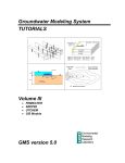
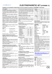
CRF-840 Rock-Fluid Centrifuge
Part No. #700-570
Instruction Manual
Updated 7/13/2015
Ver. 2.0
OFI Testing Equipment, Inc.
11302 Steeplecrest Dr. · Houston, Texas · 77065 · U.S.A.
Tele: 832.320.7300 · Fax: 713.880.9886 · www.ofite.com
Copyright OFITE 2015
©
Table of
Contents
Intro..................................................................................................2
Description.......................................................................................2
Specifications..................................................................................4
Components....................................................................................4
Procedure.........................................................................................5
Preparing the Test Cells..................................................................8
Assembly.....................................................................................8
Confining Pressure....................................................................12
Flooding the Core......................................................................14
Balancing...................................................................................15
Cell Cap Tool..............................................................................16
Software.........................................................................................17
Test Preparation.........................................................................21
Options.......................................................................................23
Tuning........................................................................................24
Strobe Calibration......................................................................26
Pixel Calibration.........................................................................28
Diagrams........................................................................................29
Warranty and Return Policy.........................................................30
OFITE, 11302 Steeplecrest Dr., Houston, TX 77065 USA / Tel: 832-320-7300 / Fax: 713-880-9886 / www.ofite.com
1
Intro
The OFITE Rock-Fluid Centrifuge simulates the effects of gravity on a core
sample. Four test cells each hold a core sample. The cells are mounted to a
rotor which spins them at up to 5,000 RPM. The centrifugal force pulls fluid
out of (or forces fluid into) the core sample. The flow of fluid is measured and
recorded over time.
Description
The Centrifuge consists of a rotor, four test cells, a vacuum chamber, a
strobe light, and a camera. The rotor and cells are housed inside the vacuum
chamber to reduce friction from air resistance.
The test cells consist of two chambers. One chamber holds the core sample
inside a rubber boot or sleeve. Outside the sleeve, the cell is capable of
holding up to 3,000 PSI of confining pressure.
The second chamber holds a clear receiver tube to hold fluid. A pair of
windows in the receiver side of the cell allow the strobe light to illuminate the
fluid inside. A camera photographs the cells as they rotate and sends the data
to a computer for analysis.
The test cell can be oriented on the rotor two ways. When the core sample
is oriented toward the rotor, fluid will drain out into the receiver tube. This is
called a Drainage test. When the core sample is oriented away from the rotor,
fluid in the receiver tube will be forced into the core sample. This is called an
Imbibition test.
As the rotor spins, the camera photographs a single line of pixels for each
cell. Each pixel is classified as either light or dark. A plastic disk floating on
top of the fluid in the receiver tube provides contrast to the interface between
the liquid and gas.
OFITE, 11302 Steeplecrest Dr., Houston, TX 77065 USA / Tel: 832-320-7300 / Fax: 713-880-9886 / www.ofite.com
2
The graph of the pixels looks similar to the image below.
C4
C2
C1
C3
Liquid
Gas
Floater
-----
C1: the liquid in the tube
C2: the floater
C3: the gas (air) in the tube
C4: the total of C1 + C2 + C3
As the test progresses and the fluid level changes, C1 and C3 will also
change. The software will record these changes and draw a graph for each
cell.
OFITE, 11302 Steeplecrest Dr., Houston, TX 77065 USA / Tel: 832-320-7300 / Fax: 713-880-9886 / www.ofite.com
3
Specifications
Components
Maximum Speed: 5,000 RPM
Maximum Temperature: 200°F (93.3°C)
Optional Maximum Temperature: 250°F (121°C)
Power Requirements: - 230 VAC, 3 Phase, Up to 30 Amp
- 230 VAC, Single Phase, 20 Amp
#127-20-004
Inlet O-ring
#700-570-015
Cell Body
#700-570-016
End Cap - Receiver Side
#700-570-017
Receiver Tube
#700-570-018Plunger
#700-570-019
Plunger End Piece
#700-570-019-2 Spacer, Rubber, ⅛"
#700-570-019-4 Spacer, Rubber, ¼"
#700-570-019-6 Spacer, Rubber, ⅜"
#700-570-020
End Cap - Core Side
#700-570-021
Locking Ring
#700-570-024
Charge Valve Assembly
#700-570-022
Valve Seat
#700-570-023
Needle Valve
#142-56O-ring
#700-570-027
Core Sleeve
#700-570-028Retainer
#700-570-030
O-ring for Cell Body
#700-570-031
O-ring for Receiver Tube
OFITE, 11302 Steeplecrest Dr., Houston, TX 77065 USA / Tel: 832-320-7300 / Fax: 713-880-9886 / www.ofite.com
4
Procedure
1. Prepare core samples 1.5" in diameter and up to 2" in length.
2. Prepare the test cells:
a. Assemble each of the four test cells with the core sample inside. See
page 8 for instructions.
b. Add confining pressure to the test cells. See page 12 for
instructions.
c. If necessary, flood the core. See page 14 for instructions.
d. Balance the test cells to prevent excessive vibration during rotation.
See page 15 for instructions.
3. Load the test cells on the rotor:
a. Choose the type of test to run. For a Drainage test, orient the cell so
that the core side is closest to the rotor. For an Imbibition test, orient
the cell so the receiver side is closest to the rotor.
b. Slide the cell into the rotor mount with the key pointed up and secure
it firmly in place with the lock.
Lock
Key
Drainage Test
Lock
Imbibition Test
OFITE, 11302 Steeplecrest Dr., Houston, TX 77065 USA / Tel: 832-320-7300 / Fax: 713-880-9886 / www.ofite.com
5
4. Close the door to the vacuum chamber and push the key forward into
position.
The Centrifuge will not operate if the key is not installed properly.
Lock
Key
5. Adjust the camera. The camera mount has two positions. For drainage
tests, position the camera away from the rotor. For imbibition tests,
position the camera close to the rotor.
a. Loosen the four locking screws (two on each side of the camera).
b. Lift the camera up out of the mounting bracket.
c. Carefully lower the camera into the correct position in the mounting
bracket.
d. Press the camera firmly down into the bracket.
e. Tighten all four locking screws.
Imbibition
Camera
Drainage
Locking Screw
Mounting Bracket
OFITE, 11302 Steeplecrest Dr., Houston, TX 77065 USA / Tel: 832-320-7300 / Fax: 713-880-9886 / www.ofite.com
6
6. Turn on the Main Power and Heat switches.
7. Close the vacuum release valve (vertical). Then turn on the Vacuum
switch.
8. Prepare the software for your test. See page 21 for instructions.
9. Make sure the Emergency Stop button is pulled out.
10.Click the “Start / Stop Test” button to begin testing.
11.When the test is complete, use the software to stop the rotor. See page
18 for instructions.
12.Turn the Vacuum and Heat switches off.
13.When the rotor has stopped spinning, open the vacuum release valve
(horizontal). This will slowly allow air back into the vacuum chamber.
14.When the pressure gauge reads 0, open the vacuum chamber and
remove the cells.
15.Disassemble the cells and clean all components thoroughly.
OFITE, 11302 Steeplecrest Dr., Houston, TX 77065 USA / Tel: 832-320-7300 / Fax: 713-880-9886 / www.ofite.com
7
Preparing the
Test Cells
Assembly
1. Prepare a core sample 1.5" (3.81 cm) in diameter and up to 2" (5.08 cm)
in length.
2. Add enough rubber spacers to the core sample to make it’s height 2". A
small overshoot is acceptable.
Rubber Spacers
Core Sample
3. Place the spacers onto the plunger end piece.
Plunger End Piece
Spacers on Plunger End Piece
4. Place the plunger on top of the rubber spacers.
Plunger
Plunger Assembly
OFITE, 11302 Steeplecrest Dr., Houston, TX 77065 USA / Tel: 832-320-7300 / Fax: 713-880-9886 / www.ofite.com
8
5. Push the core sample into the rubber sleeve.
Core Sample in Sleeve
6. On one end, push the plunger assembly into the sample boot. The
plunger end piece should be touching the core sample.
7. Press the core-side end cap into the other end of the sample boot. The
surface should be touching the core sample.
There should be no empty space inside the sample boot. Also, the
plunger should be flush with (or extend slightly beyond) the end of the
sample boot. If the plunger is recessed at all, remove it and add more
spacers.
Core-Side End Cap
Core Holder Assembly
Plunger
End Cap
OFITE, 11302 Steeplecrest Dr., Houston, TX 77065 USA / Tel: 832-320-7300 / Fax: 713-880-9886 / www.ofite.com
9
8. Stand the test cell upright with the core side facing up. Carefully lower the
core holder assembly into the test cell with the plunger pointed down. Use
the Cell Cap Tool to firmly press it into the recessed space inside the cell.
See page 16 for more information.
Core Sleeve Assembly
9. Apply Never-Seez to the threads on both the end of the test cell and the
locking ring.
10.Screw the locking ring in place on top of the end cap. Use the supplied
spanner wrench.
Be very careful not to gall the threads. If there is any resistance, slowly
unscrew the locking ring slightly and then try again. Continue working the
locking ring back and forth until it is completely tightened.
Do not use the locking ring to press the core holder assembly into
the test cell. This will damage the threads on the cell and locking
ring.
Locking Ring
OFITE, 11302 Steeplecrest Dr., Houston, TX 77065 USA / Tel: 832-320-7300 / Fax: 713-880-9886 / www.ofite.com
10
11.Turn the cell over so that the receiver side is pointing up.
12.Place a greased o-ring down into the retainer inside the cell.
Retainer
13.Carefully lower the receiver tube into the cell and gently press it into the
retainer. The retainer will center the receiver tube within the chamber
while the o-ring provides the seal.
The receiver tube is very fragile. Be very careful not to damage it.
14.Place another greased o-ring and retainer on top of the receiver tube.
This will center the tube within the chamber.
Receiver Tube
Retainer
O-ring
15.Drop the floater into the receiver tube.
16.For drainage tests, add approximately 3 mL of fluid to the receiver side
of the cell before testing. This will ensure the floater is within view of the
camera at the beginning of the test.
17.Screw the end cap into the end of the test cell to seal the receiver side of
the cell.
OFITE, 11302 Steeplecrest Dr., Houston, TX 77065 USA / Tel: 832-320-7300 / Fax: 713-880-9886 / www.ofite.com
11
Preparing the
Test Cells
Confining Pressure
For heated tests, pre-heat the cell to the test temperature before adding
confining pressure. This will prevent over-pressurization due to thermal
expansion.
1. Turn the cell so that the fluid side is pointing up.
2. Screw a charge valve into one of the ports on the end of the cell and
tighten it completely. Leave the other port open for venting.
The two ports are interchangeable.
Charge Valve
Open Valve
3. Loosen the top portion of the charge valve slightly. This will open the
valve.
4. Connect the pressure coupling to a pressure source and affix the open
end over the charge valve.
Charge Valve
Pressure Coupling
5. Slowly apply pressure to the test cell. When the pressure medium begins
venting from the other port, stop adding pressure.
OFITE, 11302 Steeplecrest Dr., Houston, TX 77065 USA / Tel: 832-320-7300 / Fax: 713-880-9886 / www.ofite.com
12
6. Screw a plug valve into the second port and tighten it completely to seal
the cell.
Charge Valve
Open Valve
7. Apply up to 3,000 PSI (20.7 MPa) to the test cell.
8. Tighten the top portion of the charge valve to close the valve and seal the
cell. Remove the pressure coupling from the charge valve.
OFITE, 11302 Steeplecrest Dr., Houston, TX 77065 USA / Tel: 832-320-7300 / Fax: 713-880-9886 / www.ofite.com
13
Preparing the
Test Cells
Flooding the Core
If the core is not already saturated, it is possible to flood the core after it is
loaded into the test cell.
1. Turn the cell so that the core side is pointing up.
2. Screw a charge valve into the port in the core-side end cap and tighten it
completely.
3. Loosen the top portion of the valve slightly to open the valve.
Fluid Return Valve
Charge Valve
4. Connect the pressure coupling to a pressure source and affix the open
end over the charge valve.
5. Apply pressure to the cell until you start to see fluid discharging into the
fluid side of the cell. This means the core sample is fully saturated.
6. Release the pressure.
7. Tighten the top portion of the charge valve to close the valve and seal the
test cell. Remove the pressure coupling from the charge valve.
8. Set the Fluid Return Valve to the correct position for your test.
Drainage: Open the Fluid Return Valve. Make sure the hole is facing
outward.
Imbibition: Close the Fluid Return Valve. Make sure the hole is facing
inward.
OFITE, 11302 Steeplecrest Dr., Houston, TX 77065 USA / Tel: 832-320-7300 / Fax: 713-880-9886 / www.ofite.com
14
Preparing the
Test Cells
Balancing
The test cells must be balanced before loading them into the centrifuge. If the
cells are out of balance, it could cause excessive vibration during testing and
possibly damage the equipment.
The cells are weighted by attaching small washers to a screw on the end of
the cell.
Screw With Washers
1. Load and assemble all four test cells. Add confining pressure and (if
necessary) flood the core.
Make sure the cell is sealed and all valves are in place before
balancing.
2. Weigh all four cells to the nearest .01 gram.
3. Place the heaviest cell on the scale and tare it.
4. Place each of the other cells on the scale (one at a time) and add weights
until the scale reads 0 ± .05 grams.
5. Weigh each cell again. Confirm that the weight of all four cells is within
.03 grams.
The closer the cells are in weight, the smoother the operation will be.
6. Do not add any more weight to any of the cells after balancing.
OFITE, 11302 Steeplecrest Dr., Houston, TX 77065 USA / Tel: 832-320-7300 / Fax: 713-880-9886 / www.ofite.com
15
Preparing the
Test Cells
Cell Cap Tool
The Cell Cap Tool is designed to help you easily insert and remove the Core
Holder Assembly into the test cell.
Insert
1. Place the test cell on the Cell Stand.
2. Gently set the Core Holder Assembly into the test cell.
3. Attach the Cell Cap Tool to the top of the test cell. Make sure the cell is
centered in the device.
4. Raise the handle and slowly press the Core Holder Assembly into the test
cell until it is completely seated.
Remove
1. Place the test cell on the Cell Stand.
2. Screw a plug into the end cap.
3. Attach the Cell Cap Tool to the top of the test cell.
Make sure the cell is centered in the device.
Plug
4. Raise the handle until the tool rests on top of the cell cap.
5. Rotate the tool until the plug engages into the hole. Then continue
rotating it until it locks in place.
6. Lower the handle slowly until the Core Holder Assembly has been
completely removed from the cell.
Plug
End Cap
OFITE, 11302 Steeplecrest Dr., Houston, TX 77065 USA / Tel: 832-320-7300 / Fax: 713-880-9886 / www.ofite.com
16
Software
To open the Rock-Fluid Centrifuge software, double-click the icon on the
computer desktop. At the bottom of the screen are five tabs that provide
access to different functions of the software. The top portion of the screen
remains the same regardless of which tab is showing.
Cell Data: Shows a real-time graph for each of the four test cells.
C1: Volume of fluid in the receiver
C2: Volume represented by the floater or two-phase interface
C3: Volume of gas (air) in the receiver
C4: Volume of the entire receiver
Valid Scans: Percentage of scans that were readable by the software
Status: Displays the current value of each of the test variables
RPM: The RPM gauge shows the RPM setpoint, the value of the
RPM Encoder, and the RPM Servo. The lines for the RPM Encoder and the
RPM Servo should coincide.
Servo Online: Turns green when the computer is successfully
communicating with the motor.
Temp Online: Turns green when the computer is successfully
communicating with the temperature controller.
OFITE, 11302 Steeplecrest Dr., Houston, TX 77065 USA / Tel: 832-320-7300 / Fax: 713-880-9886 / www.ofite.com
17
Test Control Tab
The Test Control Tab has controls for running an automatic test.
Test Header: These fields show test information you entered in the Test
Setup screen.
Test Setup Button: Click here to open the Test Editor. See page 21
for more information about the Test Editor.
Start/Stop Test Button: Click this button to start a test.
Reset Decimation Button: During a test, the software periodically takes
measurements and then delays for a period of time before measuring
again. This delay increases in length as the test progresses. This is called
Decimation. The “Reset Decimation” button sets the decimation value
back to its setting from the beginning of the test. This will provide higher
data resolution during that part of the test.
View Test Button: Click this button to view the parameters of the current
test. You can also jump to the next step or jump back to the previous step
in the test.
Comments Button: Click this button to open the Comments window.
Here you can enter comments during the test. The software will
automatically record the comments with a timestamp.
Test Setup: This field shows the protocol specified in the Test Editor.
Rotor Type: The cell orientation (Drainage / Imbibition) chosen in the
Protocol Editor
Start Date: The date and time the test was started
End Date: The date and time the test ended
OFITE, 11302 Steeplecrest Dr., Houston, TX 77065 USA / Tel: 832-320-7300 / Fax: 713-880-9886 / www.ofite.com
18
RPM Setpoint: If Manual Setpoints Mode is selected, this field sets the
motor speed. If Manual Setpoints Mode is not selected, this field shows
the current motor setpoint.
Temp Setpoint: If Manual Setpoints Mode is selected, this field sets the
temperature. If Manual Setpoints Mode is not selected, this field shows
the current temperature setpoint.
Manual Setpoints Mode: If this option is selected, the RPM Setpoint
and Temp Setpoint fields can be used to manually control the motor and
heaters.
Test Time: The elapsed time since the test was started
Estimated Completion: This field is calculated based on the test setup.
Display Mode: Select current to show the test information for the current
test. Select Archive to show test information from a previous test. To load
a previous test, select Open from the File menu.
Current File: The filename of the current test.
Archive File: The filename of the previous test that has been opened.
Export: Click this button to export the test results to Tab Separated
Values (TSV) file. This file format can be opened in MS Excel.
Summary Test Data Tab
The Summary Test Data tab shows a summary graph for each of the four
cells. Each graph plots C1, C2, and C3 with respect to time.
OFITE, 11302 Steeplecrest Dr., Houston, TX 77065 USA / Tel: 832-320-7300 / Fax: 713-880-9886 / www.ofite.com
19
Detailed Test Data Tab
The Detailed Test Data tab shows a detailed graph of one cell at a time. This
graph can plot C1, C2, C3, C4, RPM, Offset, Discriminator, Strobe Voltage,
Valid Scans, Total Scans, Temperature Control, RPM Control, Temperature
Setpoint, and RPM Setpoint.
OFITE, 11302 Steeplecrest Dr., Houston, TX 77065 USA / Tel: 832-320-7300 / Fax: 713-880-9886 / www.ofite.com
20
Software
Test Preparation
1. Open the Rock-Fluid Centrifuge software by double-clicking the icon on
the computer desktop.
2. From the Test Control tab, click the “Test Setup” button or select “Test
Editor” from the “Setup” menu.
3. Enter the test information in the fields on the left side of the screen. This
information is for display only. It does not affect the test procedure.
4. Choose a protocol.
To create or modify a protocol, click the “Protocol Editor” button.
a. To modify an existing protocol, select the name protocol name in the
list on the left. To create a new protocol, click the “New” button.
b. Enter a name in the “Name” field.
c. Under “RPM Steps”, select a duration (HH:MM:SS) and rotational
speed. Repeat this for each step in your protocol.
d. Select a Cell Position.
Drainage - The cell is positioned so that the receiver end is on the
outside. Fluid will drain out of the core sample during a test.
Imbibition - The cell is positioned with the core sample on the
outside. Fluid will be forced into the core during a test.
e. Choose a test temperature. The maximum temperature is
200°F (93.3°C) or 250°F (121°C) if the centrifuge was purchased with
the higher temperature option.
OFITE, 11302 Steeplecrest Dr., Houston, TX 77065 USA / Tel: 832-320-7300 / Fax: 713-880-9886 / www.ofite.com
21
f. If the “Wait for Temp” option is selected, the centrifuge will wait until
the temperature setpoint has been reached before beginning a test.
The “Heat-up RPM” field specifies how fast the centrifuge will spin
while waiting for the temperature.
g. Click OK.
5. Click OK.
Protocol Editor
OFITE, 11302 Steeplecrest Dr., Houston, TX 77065 USA / Tel: 832-320-7300 / Fax: 713-880-9886 / www.ofite.com
22
Software
Options
1. Click the “Options” menu at the top of the screen.
2. Enter the necessary information:
Cell Enables: Choose the cells you intend to test with. If you are only
using two cells, you can disable the other two to make data collection
more efficient.
Comm Method: Select OFIUSB
Controller CommPort: Select the COM port the controller is connected to.
RPM Conversion Factor (Hz/RPM): This number will be set at the
factory. Do not change it unless directed to by OFITE.
Pixel Conversion Factor: This value tells the software how many pixels
represent a single mL of volume in the receiver tube. To calculate this
value, use the Pixel Calibration described on page 28.
Data Period Decimation: During a test, the software periodically takes
measurements and then delays for a period of time before measuring
again. This delay increases in length as the test progresses. This is called
Decimation. The Data Period Decimation is the initial delay interval.
This value must be between 1 and 2. A value of 1 will turn off decimation
completely.
The software calculates the time of the next data collection using this
equation: (Data Decimation Period)^n Where n is a sequential number.
For example, if the Data Period Decimation is 1.25, the first data
collection will be at 1.25^1 (1.25) seconds. The second collection will
happen at 1.25^2 (1.56) seconds and the third will be at 1.25^3 (1.95)
seconds. The interval between data collections will stop increasing when
it reaches the Max Data Period (see below).
Max Data Period: This is the maximum interval the software will wait
before collecting data. This setting ensures the software continues to
collect data with a maximum delay, regardless of decimation.
Auto Inc Samp Cnt: This field sets the number of samples that are
collected in each data collection.
Eurotherm Device #: This number is set on the Eurotherm
Nominal Heat-up Rate (°C/min): Enter the approximate heat-up rate of
the instrument. The software will use this value to estimate the duration of
a test.
Archive Path: Select the folder to store test data.
3. Click “OK”.
OFITE, 11302 Steeplecrest Dr., Houston, TX 77065 USA / Tel: 832-320-7300 / Fax: 713-880-9886 / www.ofite.com
23
Software
Tuning
The Tuning tab has controls for adjusting the various instruments and running
calibration procedures. This screen includes an oscilloscope image of the test
data. Adjusting the Tuning settings will affect the oscilloscope image.
1. On the Test Control tab, check the “Manual Setpoint Mode” box, enter a
speed in the RPM Setpoint field, and hit Enter.
2. On the Tuning tab, click the Toggle Strobe button to turn on the strobe.
The oscilloscope will now display the image of the test cell.
Run State
Stop Auto / Start Auto - In Auto Mode, the instrument automatically
cycles the strobe light through each of the four test cells. It also performs
the decimation routine described on page 18. These two buttons turn
Auto Mode on and off.
Toggle Strobe - If Auto Mode is off, this button will turn the strobe light on
or off without decimation. In this mode, the strobe will only illuminate one
cell.
Reset Decimation - When Auto Mode is on, decimation is being
performed. This button resets the decimation and returns it to its original
value.
OFITE, 11302 Steeplecrest Dr., Houston, TX 77065 USA / Tel: 832-320-7300 / Fax: 713-880-9886 / www.ofite.com
24
Cells
Select Next: When Auto Mode is off but the strobe is on, only one cell is
illuminated. Click this button to cycle to the next cell.
Toggle Auto Inc: When Auto Increment is on, the strobe automatically
through each of the four cells.
Strobe Delay: Use these controls to synch the strobe with each of the four
cells. This will ensure a clear photo.
Step Negative / Positive - Adjust the timing of the strobe to fire earlier or
later in the revolution.
Reduce / Increase Step - Change the size of each adjustment.
Strobe Voltage: When testing very dark or very light fluids, it may be
necessary to adjust the strobe voltage. Dark fluids may require a higher
voltage to produce enough contrast. Light fluids may need lower voltage to
avoid washing out the image completely.
Discriminator: The discriminator is a horizontal line on the Oscilloscope
display. Any pixels that show up above this line are considered to be “light”.
Any pixels below this line are “dark”.
Increase / Decrease - Use these buttons to move the discriminator based
on the needs of your test. When using a clear sapphire receiver tube, use
a lower strobe voltage (~300V). When using the polypropylene (plastic)
receiver tube, use the maximum voltage (600V).
Rotor Type:
Drainage - Click this button if the cells are configured for drainage.
Imbibition - Click this button if the cells are configured for imbibition.
OFITE, 11302 Steeplecrest Dr., Houston, TX 77065 USA / Tel: 832-320-7300 / Fax: 713-880-9886 / www.ofite.com
25
Software
Strobe Calibration
In order to get a clear picture of the test cells, the strobe must flash when the
test cell is directly under the camera. This timing can be affected when the
instrument is moved or mechanical work is performed. The Strobe Calibration
will bring the timing back into alignment.
1. Prepare the centrifuge for testing as described on page 5.
2. On the Test Control tab, turn on Manual Setpoints Mode, enter a value in
the RPM Setpoint field, and hit Enter.
3. On the Tuning tab, click the “Toggle Strobe” button to turn the strobe on.
4. Click the “Calibrate Mode” button.
5. In the ideal Oscilloscope image, each of the four measurements (C1, C2,
C3, and C4) have well-defined boundaries that are nearly vertical and the
tops will be nearly horizontal.
Click the “Step Negative” button until the image begins to visibly degrade.
OFITE, 11302 Steeplecrest Dr., Houston, TX 77065 USA / Tel: 832-320-7300 / Fax: 713-880-9886 / www.ofite.com
26
6. Click the “Mark Left Limit” button.
7. Now click the “Step Positive” button until the image begins to degrade in
the other direction.
8. Click the “Mark Right Limit” button.
9. Click the “Send to Center” button. This will center the strobe timing
between the left and right extremes.
10.Observe the Oscilloscope. If the image appears to be of good quality,
click the “Save Period” button.
11.On the Test Control tab, enter a new value in the RPM Setpoint field and
click Enter.
12.Repeat steps 5 – 10.
13.The Centrifuge requires at least two calibration points, however more are
acceptable. Repeat this process with all the desired points.
14.Click the “Calc Fit” button. This will save the calibration and exit
Calibration Mode.
OFITE, 11302 Steeplecrest Dr., Houston, TX 77065 USA / Tel: 832-320-7300 / Fax: 713-880-9886 / www.ofite.com
27
Software
Pixel Calibration
The Pixel Calibration provides a conversion factor from pixels to volume
(mL). This value should then be entered into the Options screen so that the
software can accurately calculate the volume.
1. Prepare the centrifuge for testing as described on page 5.
2. On the Test Control tab, turn on Manual Setpoints Mode, enter a value in
the RPM Setpoint field, and hit Enter.
3. Click the “Pixel Calibration” button.
4. Click the “Toggle Strobe” button to turn on the strobe.
5. Choose a cell to test. Click the “Select Next Cell” button until that cell is
selected.
6. Enter a number in the “Number of Samples” field. A higher number of
samples with give better results.
7. Click the “Collect” button. The software will begin recording C1, C2, C3,
and C4 values and calculating the mean and standard deviation.
8. When all the data has been collected, record the C1 Mean value.
9. On the Test Control tab, enter 0 in the RPM Setpoint field and hit Enter.
10.Remove the cell from the centrifuge, add a known amount of fluid to the
receiver tube and place it back in the centrifuge.
11.Repeat steps 2 – 8.
12.When all the data has been collected, subtract the first C1 Mean from the
second C1 Mean and divide the result by the volume that was added to
the cell. This will give you the Pixel Conversion Factor.
13.Click the Options menu.
14.Enter the Pixel Conversion Factor and click OK.
OFITE, 11302 Steeplecrest Dr., Houston, TX 77065 USA / Tel: 832-320-7300 / Fax: 713-880-9886 / www.ofite.com
28
Diagrams
Locking Ring
(#700-570-021)
O-ring (#700-570-030)
End Cap - Core Side
(#700-570-020)
Core Sleeve
(#700-570-027)
Rubber Spacer
O-ring (#127-20-004)
Plunger End Piece
(#700-570-019)
Plunger
(#700-570-018)
Cell Body
(#700-570-015)
Window
O-ring (#700-570-031)
Receiver Tube
(#700-570-017)
Retainer
(#700-570-028)
End Cap - Receiver Side
(#700-570-016)
OFITE, 11302 Steeplecrest Dr., Houston, TX 77065 USA / Tel: 832-320-7300 / Fax: 713-880-9886 / www.ofite.com
29
Warranty and
Return Policy
Warranty:
OFI Testing Equipment, Inc. (OFITE) warrants that the products shall be free from liens and defects in
title, and shall conform in all respects to the terms of the sales order and the specifications applicable to
the products. All products shall be furnished subject to OFITE’s standard manufacturing variations and
practices. Unless the warranty period is otherwise extended in writing, the following warranty shall apply:
if, at any time prior to twelve (12) months from the date of invoice, the products, or any part thereof, do
not conform to these warranties or to the specifications applicable thereto, and OFITE is so notified in
writing upon discovery, OFITE shall promptly repair or replace the defective products. Notwithstanding
the foregoing, OFITE’s warranty obligations shall not extend to any use by the buyer of the products in
conditions more severe than OFITE’s recommendations, nor to any defects which were visually observable
by the buyer but which are not promptly brought to OFITE’s attention.
In the event that the buyer has purchased installation and commissioning services on applicable products,
the above warranty shall extend for an additional period of twelve (12) months from the date of the original
warranty expiration for such products.
In the event that OFITE is requested to provide customized research and development for the buyer,
OFITE shall use its best efforts but makes no guarantees to the buyer that any products will be provided.
OFITE makes no other warranties or guarantees to the buyer, either express or implied, and the warranties
provided in this clause shall be exclusive of any other warranties including ANY IMPLIED OR STATUTORY
WARRANTIES OF FITNESS FOR PURPOSE, MERCHANTABILITY, AND OTHER STATUTORY
REMEDIES WHICH ARE WAIVED.
This limited warranty does not cover any losses or damages that occur as a result of:
•
Improper installation or maintenance of the products
•
Misuse
•
Neglect
•
Adjustment by non-authorized sources
•
Improper environment
•
Excessive or inadequate heating or air conditioning or electrical power failures, surges, or other
irregularities
•
Equipment, products, or material not manufactured by OFITE
•
Firmware or hardware that have been modified or altered by a third party
•
Consumable parts (bearings, accessories, etc.)
Returns and Repairs:
Items being returned must be carefully packaged to prevent damage in shipment and insured against
possible damage or loss. OFITE will not be responsible for equipment damaged due to insufficient
packaging.
Any non-defective items returned to OFITE within ninety (90) days of invoice are subject to a 15%
restocking fee. Items returned must be received by OFITE in original condition for it to be accepted.
Reagents and special order items will not be accepted for return or refund.
OFITE employs experienced personnel to service and repair equipment manufactured by us, as well as
other companies. To help expedite the repair process, please include a repair form with all equipment
sent to OFITE for repair. Be sure to include your name, company name, phone number, email address,
detailed description of work to be done, purchase order number, and a shipping address for returning the
equipment. All repairs performed as “repair as needed” are subject to the ninety (90) day limited warranty.
All “Certified Repairs” are subject to the twelve (12) month limited warranty.
Returns and potential warranty repairs require a Return Material Authorization (RMA) number. An RMA
form is available from your sales or service representative.
Please ship all equipment (with the RMA number for returns or warranty repairs) to the following address:
OFI Testing Equipment, Inc.
Attn: Repair Department
11302 Steeplecrest Dr.
Houston, TX 77065
USA
OFITE also offers competitive service contracts for repairing and/or maintaining your lab equipment,
including equipment from other manufacturers. For more information about our technical support and
repair services, please contact [email protected].
OFITE, 11302 Steeplecrest Dr., Houston, TX 77065 USA / Tel: 832-320-7300 / Fax: 713-880-9886 / www.ofite.com
30