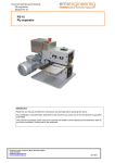
Download Model 136 Hand-Operated Bench Numbering Press
Transcript
NUMBERALL
STAMP & TOOL CO., INC.
USER MANUAL & PARTS LIST
MODEL
136
S/N:
___________________________
P.O. BOX 187, 1 HIGH ST.
SANGERVILLE, ME 04479
www.numberall.com
[email protected]
TEL: 207-876-3541
FAX: 207-876-3566
MODEL 136 HAND-OPERATED
BENCH NUMBERING PRESS
Uncrating Procedure
1. The Model 136 is shipped bolted to a wooden skid. It is covered with a
cardboard box that is stapled and banded to the wooden skid.
2. Cut the plastic shipping bands. Cut the cardboard box all the way around,
within a couple of inches of the top of the wooden skid.
3. Lift off the cardboard cover, remove the protective plastic bag and unbolt the
press.
4. The Model 136 weighs 65 pounds and should be lifted with caution.
5. Bolt the press securely to a solid bench to avoid accidental upset.
6. The Model 136 is capable of forces exceeding 2 tons. KEEP BOTH HANDS
FREE OF THE TABLE AREA WHEN OPERATING THE PRESS HANDLE.
7. Any shipping damage to the press must be reported immediately to the
common carrier and to Numberall.
Product Description
The Model 136 is a versatile and compact press designed for stamping
nameplates and small parts. The Model 136 is an ideal choice where bench
space is restricted. It is intended for continuous, heavy-duty use.
Bench area is 12” x 10” x 11-1/2” high. The handle extends upward to about 19”
above the base. The mounting base is 7” x 11-3/4” (outside dimensions). Throat
depth is 3”, maximum clearance between the ram and table is 4”, and table travel
is 2”. The optional adjustable table requires a bench area of 13” x 14-1/2” x 111/2” high.
An adjustable table is available as an option. It permits left, right, fore and aft
movement of a clamped part. An automatic tripping attachment is another option
available, which when using the Model 50 Numbering Machine, allows the Model
50 to advance to the next consecutive number.
Revision # 2.0
Maximum Character Chart
The Model 136 can easily exert a 3-ton force. The following chart depicts the
maximum number of characters the Model 136 is capable of stamping during
each impression, based on character size and type of material. The chart is
conservative, so the recommendations can be exceeded in many cases.
Variations in the hardness of a material will affect stamping results.
Character
Size
Steel RC 30
Mild Steel
Soft Brass
Aluminum
1100 H26
1/4
2
2
4
12
3/16
2
4
5
16
5/32
3
5
8
30
1/8
4
6
13
40
3/32
4
7
15
50
1/16
6
11
24
80
Note: The above chart is based upon the maximum number of characters for a
legible impression (.002”-.003” depth).
Function of Controls
1. OPERATING HANDLE (136-82) - The operating handle is located on the right
side of the press. CAUTION: When experimenting with the handle, KEEP
HANDS CLEAR OF TABLE. The handle should be cycled completely from
upper to lower stops. The handle should not be allowed to snap back, but
rather returned gently.
2. CAMSHAFT STOP ARM STOPS (136-80) - These eccentric stops located on
the right inside of the frame-casting, limit the handle travel. By loosening the
allen head cap screws, the steel eccentrics can be rotated changing the
effective stop location. Tighten the cap screws after adjustment. These stops
are pre-adjusted at the factory and normally do not need further adjustment.
3. TABLE ELEVATION NUT (136-98) - This knurled nut, located in the front
near the base of the frame casting, adjusts the height of the table. Turning the
nut counter-clockwise lowers the table. Turning the nut clockwise raises the
table.
Revision # 2.0
4. TABLE INSERT CLAMP (136-17) - This clamp located on the left hand side
of the table, secures the table insert. After loosening the brass screw, the
insert can be moved fore and aft. Engraved markings on the left hand edge of
the insert are provided for reference purposes. Each increment is 1/16”. An
arrow index is stamped on the left hand guide rail.
5. TABLE LOCKING ASSEMBLY (136-24) - The table locking assembly located
beneath the table in the front center, secures the table. After loosening the
wing nut, the table may be moved left or right. Tighten the wing nut after
adjustment.
6. MARKING DEVICE CLAMPING SCREW (136-92) - The brass screw located
on the right hand side of the dovetail ram (136-90), secures the marking
device. The dovetail and clamping screw only serve to hold the marking
device in position. The press force bears on the ram head bottom.
7. DOVETAIL RAM GIB (136-94) - This gib located between the dovetail ram
(136-90) and the frame casting (136-142) eliminates play in the ram head. If
the ram head develops left and right play, it will be necessary to tighten the
gib. While holding the two allen head setscrews (136-96) stationary, loosen
the locking nut on each. Evenly tighten the two setscrews until left and right
play is eliminated. Do not over tighten. While holding the two allen head set
screws stationary, retighten the locking nuts. This adjustment may be
required after initial break-in.
Adjustments for Stamping
1. Lower the table, by rotating the elevation nut counter-clockwise, until the
marking device can easily be inserted in the dovetail ram.
2. Place the material to be stamped or trial sample in the nameplate clamp or
fixture.
3. Grab the handle and slowly lower it watching the surface of the material to be
stamped. CAUTION: KEEP BOTH HANDS CLEAR OF THE TABLE AREA.
If the marking device begins to touch the surface, lower the table further, until
the handle reaches the lower stop and the marking device does not touch the
material.
4. With the handle held on the lower stop, raise the table until it touches the
marking device.
5. Raise the handle gently. Raise the table very slightly (1/16 of a turn at a time).
Lower the handle all the way to the lower stop and raise it gently. Check the
impression. If not deep enough keep rotating the elevation nut and checking
the impression until a satisfactory stamp is achieved. Make sure the handle
Revision # 2.0
reaches the lower stop each time. This the only way to accurately control the
depth of impression.
6. Once adjusted the Model 136 is ready for stamping. Minor adjustments may
be required due to variations in the thickness of the part.
Lubrication
1. Oil holes are provided in the following places:
a. On the top of the ram head (136-90)
b. On the rocker arm (136-40), above the rocker arm shaft (136-62).
Use a few drops of light oil in these places if the surface appears dry. Oil daily if
the press is in continuous service.
2. An oil cup (136-234) is attached to the brass rod end bearing (136-230) inside
the press. Keep the oil cup half-full with light machine oil.
3. On the table insert guides and the table dovetail guide, use graphite as a
lubricant. Oil should not be used, as it may accumulate dirt and bind the parts.
4. Place a few drops of oil on the table elevation nut if it appears dry. Oil weekly
if the press is in continuous service.
5. Place a few drops of oil on the ram head dovetail slides if the surfaces appear
dry. Oil weekly if the press is in continuous service.
Revision # 2.0
INSTALLATION OF OPTIONAL TRIPPING ATTACHMENT
The following instructions apply to any of Numberall’s bench presses: Models
131, 131A, 133, 136, 136A, and 137.
1. The tripping attachment is shipped assembled but will need adjustment. All
mounting holes in the press have been pre-drilled. The hand clearances
inside the casting are very tight and some patience is required. CAUTION:
WHEN WORKING WITH THE CASTING, MAKE SURE ALL POWER
SOURCES HAVE BEEN DISCONNECTED. The tripping attachment is easily
installed if the press is lying on its side.
2. The linkage will attach to the press with the turnbuckle assembly (*-116)
toward the rear. It is located on the right hand side of the frame casting,
bolting to the rocker arm and frame casting.
3. Loosen the two jam nuts on the turnbuckle assembly. One is a left hand
thread and one is a right hand thread.
4. Insert the 1/4” cap screw through the lower ball end and thread it into the 1/4”
hole in the right rear inside of the frame casting.
5. Insert the shoulder screw (*-114) through the tripping arm from the right. Slide
the spacer over the shoulder screw. Start the shoulder screw into the
threaded hold near the back of the rocker arm. Tighten the shoulder screw.
6. Adjust the rear turnbuckle assembly by rotating the center rod until 3/4” of
clearance exists between the tripping arm and the top of the dovetail ram.
Tighten both turnbuckle jam nuts while holding the turnbuckle rod stationary.
7. Tighten the free motion connecting link assembly into the Model 50 Automatic
Numbering Machine. Tighten the jam nut so that the ball end is aligned
vertically.
8. Start the free-motion rod into the free-motion connecting link.
9. By rotating the actuating arms away from the numbering machine, it will be
possible to simultaneously feed the free motion rod into the free motion
linkage and slide the numbering machine into the dovetail ram. Tighten the
marking device clamping screw.
10. After the press has been properly adjusted for the impression depth, cycle the
press. If the numbering machine is not advancing properly, it will be
necessary to screw the free motion rod either in or out of the upper ball end.
Loosen the jam nut first. Adjust the rod until the numbering machine clicks
into its advance position. Make sure the press makes a full cycle. If it does
Revision # 2.0
not, then the adjustment to the tripping attachment will not be correct. Tighten
the jam nut.
11. The tripping attachment is now ready for use. Do not operate a press with the
tripping attachment, unless it is connected to an automatic numbering
machine or the free motion rod and ball end have been removed, otherwise
damage to the tripping attachment may occur.
* Denotes the model number of the press for which you are installing the attachment.
Revision # 2.0
Numberall Stamp & Tool Co., Inc.
For extra copies of this manual please call or
visit our website.
P.O. BOX 187, 1 HIGH ST.
SANGERVILLE, ME 04479
www.numberall.com
[email protected]
TEL: 207-876-3541
FAX: 207-876-3566


