1
Publication: BI-IOM-008A
INSTALLATION, OPERATION
AND MAINTENANCE
MANUAL
*
* MANUFACTURED BY BEELER INDUSTRIES UNDER LICENSED AGREEMENT
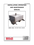
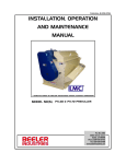
MODEL NO(S). SR-36 & SR-48 SHEAR ROLL
CR-30 & CR-42 CRACKER
30" & 42" FEEDER
P.O. Box 380
4664 Kiernan Court,
Salida, CA 95368
Phone: 209-545-0740
Fax 209-545-0768
www.beelerindustires.com
BEELER INDUSTRIES
Publication: BI-IOM-008A
IMPORTANT SAFETY INFORMATION
Before installing, operating or maintaining this machine you must read and understand the contents of
this manual. Failure to do so may result in equipment damage, injury or death.
Antes de la instalación, funcionamiento o mantenimiento de este equipo debe leer y comprender el
contenido de este manual. El no hacerlo puede resultar en daño al equipo, lesiones o la muerte.
Safety Labels
Lock Out / Tag Out
Throughout this manual and on the machine,
safety labels have been placed to bring attention
to characteristics of this equipment that warrant
particular awareness.
There are potential
hazards on any device and care should be
exercised whenever installing, operating or
maintaining any equipment.
It is the user's responsibility to ensure that proper
LOCK OUT / TAG OUT procedures are
implemented throughout the facility.
Follow
your facilities Lock Out/Tag Out procedures.
Prior to any maintenance, service or cleaning of
any equipment it should be locked out and
tagged out from all potential sources of energy
(electrical, pneumatic, hydraulic, mechanical,
etc.) Failure to do so will endanger the user and
others and may lead to damage, severe injury or
even death.
Ensure that all original labels are maintained in
good condition. In the event that labels are
rendered illegible contact Beeler Industries for
replacement labels.
Danger:
Indicates an imminently
hazardous situation, which, if
not avoided, will result in
death or serious injury. This
signal word is to be limited to
the most extreme situations.
Caution:
Indicates a potentially
hazardous situation, which, if
not avoided, may result in minor
or moderate injury. It may also
be used to alert against unsafe
practices.
Warning:
Indicates a potentiall y
hazardous situation, which, if
not avoided, could result
in death or serious injury.
Take the time to
be safe!
2
BEELER INDUSTRIES
Publication: BI-IOM-008A
SECTION 1
TABLE OF CONTENTS
GENERAL INFORMATION
SECTION 1 - GENERAL INFORMATION
1-1 Introduction
Thank you for purchasing an LMC Shear Roll/
Cracker. Your new shear roll/cracker is built to
the highest industry standards. Great care has
been taken to design and manufacture a high
quality, low maintenance product that is
economical to use and maintain.
1-1 Introduction
1-2 Contacting Beeler
Industries
1-3 Purpose and Scope
This manual is intended to assist in the
installation, operation and maintenance of your
shear roll / cracker. The instructions in this
manual are general in nature and apply to a
variety of models. Each situation dictates the
need for any special precautions, and it is the
user's responsibility to ensure that adequate
safety measures are employed in installation,
operation and maintenance. As always, follow
good safety practices around all equipment.
1-4 Receipt of Product
1-5 Precautions of Use and
Installation
SECTION 2 - OPERATION AND
MAINTENANCE
2-1 Operation and Adjustments
2-2 Lubrication
2-3 Model Variations
1-2 Contacting Beeler Industries
Beeler Industries, Incorporated
SECTION 3 - VIEWS AND PARTS LIST
3-1 Serial Number Location
3-2 Parts Location Drawing
Mail:
P.O. Box 380
Physical:
4664 Kiernan Court
Salida CA 95368
3-4 Maintenance Record Sheet
Main Office:
(209) 545-0740
Sales:
(209) 613-0407
Parts:
(209) 545-0740
Service:
(209) 613-0407
Fax:
(209) 545-0768
email: [email protected]
Website: www.beelerindustries.com
1-3 Purpose and Scope
This manual provides installation, operation and
maintenance procedures for standard shear roll /
crackers.
Due to variations in design and
manufacture for unique customer needs, not all
shear roll / crackers might be covered. For
special assistance, please contact Beeler
Industries Service for additional information.
3
BEELER INDUSTRIES
Publication: BI-IOM-008A
SECTION 2
1-4 Receipt of Product
OPERATION &
MAINTENANCE
All shipments should be immediately checked
for proper product and quantity upon receipt
and inspected for any visible defects or
damage.
Any discrepancies should
immediately be reported to Beeler Industries
and the freight provider. If installation is
provided by Beeler Industries, this inspection
may be performed by Beeler personnel.
2-1 Operation and Adjustment
Shear Roll
The shear roll splits open the two halves of the
nut shell by passing the nut between a rubber
belt and a rubber roll with different linear speeds.
1-5 Precautions of Use and Installation
The pressure with which the belt and roll hold the
shell as it passes between them is a function of
the gap between the roll and belt. The belt
support roll is spring mounted allowing a variety
of sizes as well as foreign material to pass
through without damaging the meat or the
machine.
1. Use only qualified personnel for installation
and wiring of the shear roll / cracker.
Personnel are required to be familiar with the
general use of required tools for installation
of this unit. Should you require assistance in
the installation, Beeler Industries offers such
a service.
Please contact our Service
Department for estimates and scheduling.
After shearing, the belt carries the product to the
built-in aspirator. The shell is lifted by the air
stream and the meats are dropped through to the
discharge. The lifted material may be observed at
the window above the discharge however the
airstream should be sampled using an optionally
available sample box.
2. Lifting/moving/positioning: The shear roll /
cracker assembly is top heavy however it
may be lifted with a fork truck under the
shear roll frame. Secure shear roll to forks to
prevent tipping. Move slowly and descend
grades in reverse. When moving cracker
assembly as a separate unit use lifting straps
and clevises on the three lift ears provided.
It is important that the shear roll in-feed is
metered through a feeder pan to evenly distribute
as well as control input flow. If product is not
distributed across the full width of the roll it will
wear unevenly requiring truing or replacement.
3. The standard motors specifications provided
are listed in table 1.1 unless otherwise
specified in the purchase contract. All wiring
must be run in conduit and installed per local
and state code by a qualified electrician. A
manual electrical lock-out for maintenance
must be provided by the owner prior to
operation. Typical installations include a
customer provide variable frequency drive for
the rubber roll drive motor.
MODEL
HP
V/F/PH
QTY
SR-30
3
230/460/60/3
2
SR-48
3
230/460/60/3
2
CR-30
1
230/460/60/3
1
CR-42
1.5
230/460/60/3
1
30" FEEDER
0.24
460/60/3
1
42" FEEDER
0.42
460/60/3
1
TABLE 1.1
Adjustment
1. Rotate the crank handle located on the
rubber roll bearing adjuster to raise and
lower the rubber roll. As the roll wears it will
need to be lowered to make up for wear. As
the roll wears the linear speed of the roll is
reduced therefore the customer provided
variable frequency drive should be adjusted
to increase the speed.
2. The amount and density of product that will
be lifted by the aspirator will depend on the
air flow provide by the customer's air
system. Initially the bleed on the aspirator
should be closed via the thumbwheel then
the air systems blast gate should be adjust
to just lift all the discharge. At this point the
bleed should be opened to a point that
drops the good product to the discharge
while still lifting the majority of the shell.
MOTOR SPECIFICATIONS
4
BEELER INDUSTRIES
Publication: BI-IOM-008A
This adjustment is made through iteration
and experience as well as customer
preference.
Cleaner discharge will be
produced if some good product is allowed to
be lifted with the shell. Likewise allowing
some shell in with the good product will
reduce loss of good product. By trial and
error the system blast gate may be adjusted
down to conserve system air still allowing
enough adjustment to the bleed to allow for
variations in product.
belt sag is approximately halfway up
the face of the white guide rollers on
each side of the belt. Too much
tension will shorten bearing life and
too little will cause slippage under
load.
11) Replace guards and panels. Run
machine and observe tracking.
Adjust as necessary.
Rubber roll replacement. Over time the
rubber roll will wear and become too
small to work properly. At this point it
should be replaced with a new or
reconditioned roll. To replace roll follow
these steps.
3. Shear belt adjustment is necessary when
replacing belt or when tracking problems
arise. The drive and tail pulley are designed
with a slight taper at each end. This allows
the belt to track with minimal tension and
without the problems common to straight
pulleys. To remove shear belt follow the
steps below:
1) Lock out and tag out per your facilities
procedure.
2) Remove belt guard.
1.) Lock out and tag out per your facilities
procedure.
3) Loosen adjuster cross shaft coupling
bolts and remove shaft.
2.) Remove belt guard and body panel
on opposite side.
4) Remove top cover panel exposing
rubber roll.
3.) Remove both drive v-belts.
5) Remove bearing adjuster assembly to
frame mount bolts.
4.) Loosen tail end bearing mount bolts
and adjust bearing tension bolt
counterclockwise until bearing
bottoms out in adjustment slot.
6) Using appropriate lift equipment as
well as straps and clevis lift roll with
adjusters up out of the body of the
shear roll. The adjusters may swing
down as the roll is lifted so they must
be protected from damage or from
causing damage.
5.) Starting with the tail bearing on the
non-drive side insert shaft tool into
shaft end recess. Support shaft tool
and remove bearing mount bolts on
non-drive side only.
Lower shaft
support tool until shear belt top clears
the bottom of frame rail.
7) Set roll down on work bench and
secure in place.
8) Measure and record distance from
end of shaft to edge of bearing.
6) Repeat step 4 for remaining shafts.
7) Slide belt off of pulleys. Caution! The
belt is heavy and will require a
minimum of two persons to safely
manipulate it.
9) Loosen bearing set screws and slide
bearing assemblies off of shaft.
10) If replacing roll with new shaft
mounted roll go to step 14
8) Install new genuine LMC shear belt in
reverse order of above steps.
11) Measure and record distance from
end of shaft to face of bushing.
9) Adjust tension evenly on both sides.
Use a tape measure to check
centers on tail and drive shaft.
Ensure that they are the same. A
slight variation of 3/16" is permissible
due to manufacturing tolerances of
the shear belt.
12) Loosen bushing set screws and
remove bushing mount bolts. On QD
style bushings place bolts into
threaded holes on bushing and
alternately and incrementally tighten
the bolts to extract the bushing. On
taper-lock bushings place setscrews
10) Belt tension should be set so that the
5
BEELER INDUSTRIES
Publication: BI-IOM-008A
in threaded holes on bushing and
alternately and incrementally
tighten until bushing is extracted.
Remove shaft.
re-tension. Run the rolls out all the way
and then back to recheck the gap. Repeat
above steps until proper equal
measurements are achieved. Replace all
guards, etc. prior to restarting cracker.
13) Install shaft into reconditioned
rubber roll setting bushings at
position recorded in step 11.
MEASURE
14) Install bearing adjuster assemblies
at positions recorded in step 8.
15) Lift roll into place and re-install per
steps 1-7 in reverse order.
Cracker
The cracker is used to break the shell of
hard shell varieties by passing it between
two hardened grooved rolls turning at
different speeds. The gap between the
rolls controls the pressure applied to the
shell. The adjustable roll is also spring
mounted allowing larger foreign material to
pass through without stopping or damaging
the rolls.
BEARING STOP
FIG. 2.1 CRACKER ROLL CHECK
3. Belt tensioning: Matched belts require
inspection every one thousand eighty
(1080) hours of operation. Check for
worn or frayed belts and worn sheaves.
Replace as necessary.
Tension is
determined by spring tensioner so no
adjustment is necessary or available.
Inspect spring for signs of fatigue.
Replace spring if cracked or discolored.
As with the shear roll the product entering
the cracker should be both metered and
evenly distributed.
Better results are
achieved with singulation of product at the
in-feed.
Feeders
Adjustment
The vibratory feeders are used to meter
and spread the flow of incoming product.
The feeder is compression spring mounted
and driven by an eccentric vibratory motor.
The eccentrics are factory set for correct
feeder performance.
1. Roll gap is adjusted by turning the large
hand wheel on the front of the machine.
Clockwise rotation closes the gap, counterclockwise rotation opens the gap See item
5 on figure 3.2.
2. It is critical for consistent cracking that the
rolls be parallel. Rolls should be checked
periodically to ensure an even gap. Gap
may become uneven over time as the
chain connecting the two adjusters
slackens. To re-establish proper gap turn
machine off and follow lock out / tag out
procedure. Remove the belt guard so the
bearings and shafts are visible. Turn the
roll adjustment handle clockwise until one
bearing contacts the "C" shaped stop plate.
See figure 2.1. Check the center distance
between the fixed roll shaft and the
movable roll shaft on both sides of the
machine. It is easier to check shaft edge to
shaft edge than to find centers. If there is a
significant distance (> 1/16") then remove
the chain and turn the handle to even out
the measurements. Replace the chain and
Adjustment
1. The feeder pan may be adjusted to tip the
discharge edge. Four 3/8 bolts hold the
pan spring mounts to the mounting frame.
Typically the pan is adjusted so the four
bolts are in the center of the adjustment
slots. If increased feed is desired the pan
can be adjusted to tip the discharge edge
slightly forward. Ensure the pan is free to
move without rubbing or hitting any
surrounding metal work.
2. The vibrator should be set to 50%.
Any increase in force may lead to
premature pan failure. Prior to service lock
out / tag out. The vibrator is adjusted by
removing the two end caps exposing the
eccentric weights. The outer weights may
be adjusted relative to the inner weights
6
BEELER INDUSTRIES
Publication: BI-IOM-008A
using the percentage markings on the inner
weight as a guide. See fig 2.2. It is of utmost
importance that both sides of the vibrator are
set identically. Any disparity in the weight
settings will lead to motor failure.
can be obtained through Beeler Industries
directly by contacting our Parts
Department at (209) 545-0740 or through
your Beeler Sales representative. When
ordering, please supply the nameplate
serial number information located on the
Beeler red tag secured to the frame of the
Shear roll/cracker.
Refer to section 3-2 for part identifying /
locating and for common part listing and
order identification number. Contact our
service department for required parts not
identified on those pages.
2-3 Model Variation
Standard shear roll / crackers are built with
drive components on the left as viewed in the
direction of product flow. Units may be
ordered with right hand drive. Standard
power requirements are listed in table 1.1.
Units for export may be ordered with
appropriate voltage and frequency.
FIG. 2.2 Vibrator eccentric weights
2-2 Lubrication
Contact Beeler Industries Customer Service
with any questions resulting from machine
variations.
1. Ball bearings equipped with grease (zerk)
fittings should be manually lubricated with
one half (½) pump of Food Grade NLGI 2
grease every one hundred twenty (120)
hours of operation. Bearings without fittings
should be replaced after five thousand
(5000) hours of operation.
3-1 SERIAL NUMBER LOCATION
It is important to have the serial number
information when contacting Beeler
Industries regarding service information or
parts ordering. The number is stamped on
the identification plate located per the
illustration below.
2. Chain drives require a manual application of
FDA CFR-178.3570 food grade grease
about the chain contact inner-teeth of both
drive and driven sprockets every one
hundred eighty (180) hours of operation.
ON CRACKER
3. The Shear roll is equipped with Dodge
Quantis or SEW Eurodrive gear reducers
and comes pre-lubricated from Beeler
Industries. The oil level should be flush to
the level plug located approximately one
and one half inches (1-1/2") up from the
base and checked prior to initial use and
every one hundred eighty (180) hours of
operation. Change the oil using Mobil SHC
630 every five thousand (5000) hours or
every three years whichever is less.
(on back side)
ON SHEAR ROLL
2-3 Repair Parts
FIG. 3.1 SERIAL PLATE LOCATIONS
Necessary repair and maintenance parts
7
BEELER INDUSTRIES
Publication: BI-IOM-008A
FIG. 3.2 SHEAR ROLL ASSEMBLY
8
BEELER INDUSTRIES
ITEM #REQ
DESCRIPTION
PART #
Publication: BI-IOM-008A
FIG. 3.3 CRACKER ASSEMBLY
9
BEELER INDUSTRIES
Publication: BI-IOM-008A
FIG. 3.4 FEEDER ASSEMBLY
10
BEELER INDUSTRIES
Publication: BI-IOM-008A
SECTION 3,3
NOTES
11
BEELER INDUSTRIES
Publication: BI-IOM-008A
Non-Liability
The information contained in this manual has
been compiled by Beeler Industries with high
diligence to ensure correct information.
injuries of body or health is based on deliberate
or careless delinquency of Beeler Industries.
Beeler Industries does not assume liability for
eventually wrong conclusions and results arising
from this. The notes given in the manual describe
the most common fault reasons. But often there
are further reasons for existing faults, which
cannot be listed here, or there are further
sources of error, which are unknown yet. Beeler
Industries does not assume liability for failed or
unnecessary repair work. Beeler Industries does
not assume liability for appliance of data and
information, which either turn out as wrong, were
incorrectly described or faults, which by mistake
appeared during data compilation. Without
restriction of the above mentioned facts, Beeler
Industries does not assume liability for any loss
regarding profits, company value or any other,
also economic, loss arising from this.
No matter which legal justifications are present,
Beeler Industries is liable for compensation only
in case of intention, gross negligence and in
warranty of assured quality. Warranties of
assured qualities require the explicit written
statement.
Liability according to product liability law shall
remain unaffected. Beeler Industries reserves the
right of user’s contributory negligence argument.
Beeler Industries is not liable to pay
compensation for damages, which arise from
misusage of the subject matter of the contract,
even if Beeler Industries has been informed on
the possibility of this damage. The liability of
Beeler Industries is confined to the real price paid
for the product. Beeler Industries takes no liability
for damage or operating troubles arising from
non-compliance of this user manual and the
special safety precautions mentioned there. The
burden of proof is on the user of the device, that
he has paid attention to technical explanations,
notes on operation, equipment care as well as
maintenance and safety without exception. This
non-liability does not hold, if any damage from
12