1
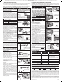
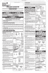
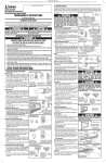
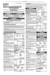
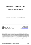
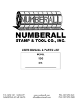
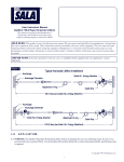
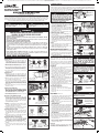
PRINTER’S INSTRUCTIONS:
INSTR,HOMEOWNERS,LDO W/MCT3; LINEAR P/N: 223710 C; INK: BLACK; MATERIAL: 20# MEAD BOND; SIZE: 11.000” x 17.000”; FOLDING: 1-FOLD VERTICAL, 1-FOLD HORIZONTAL, FINISH 8.500” X 5.500” WITH LOGO SHOWING; SCALE: 1-1; SIDE 1 OF 2
PROFESSIONAL INSTALLATION BY:
2 Remote Controls
This opener is supplied with a three-button remote control (the second and third buttons can be used to control an
additional operator or gate if it contains a Linear MegaCode™ receiver). Additional single and multi-button remote
controls can be purchased. An unlimited number of remote controls can be used with this operator. The short white
wire on the back of the operator serves as an antenna for PREPARING TO ADD A REMOTE
the remote controls. Do not cut off the white wire or the
remote controls will not operate well.
2
MODELS LDO33 & LDO50
BELT-DRIVE OR CHAIN-DRIVE
GARAGE DOOR OPENERS
HOMEOWNER’S INSTRUCTIONS
  WARNING
For Sectional and Jamb Type Doors
IMPORTANT SAFETY NOTES
Please read the instructions carefully! This garage door opener is designed to provide safe and reliable service if installed
and tested as described in these instructions. A garage door is the largest mechanical appliance in a residence. Care
must be taken to prevent injury or death during installation and operation of the garage door and garage door opener.
THE FOLLOWING FORMATS ARE USED FOR SAFETY NOTES IN THESE INSTRUCTIONS.
  WARNING
This type of warning note is used to indicate
possible mechanical hazards that may cause
serious injuries or death.
  CAUTION
This type of warning note is used to indicate
the possibility of damage to the garage door or
garage door opener.
IMPORTANT USER SAFETY INSTRUCTIONS
  WARNING
A MOVING GARAGE DOOR CAN CAUSE INJURY OR DEATH!
TO REDUCE THE RISK OF DEATH OR SEVERE INJURY:
1 READ AND FOLLOW ALL INSTRUCTIONS.
2 NEVER LET CHILDREN OPERATE, OR PLAY WITH DOOR CONTROLS! KEEP REMOTE CONTROL
AWAY FROM CHILDREN!
3 Always keep moving door in sight and away from people and objects until it is completely closed. NO
ONE SHOULD CROSS THE PATH OF THE MOVING DOOR.
4 NEVER GO UNDER A STOPPED, PARTIALLY OPEN DOOR.
5 Test door opener monthly. The garage door MUST reverse on contact with a 1-1/2 inch object (or
a 2x4 board laid flat at the center of the door) on the floor. If adjusting either the force or the limit
of travel, re-test the door opener. Failure to adjust the opener properly may cause severe injury or
death.
6 If possible, use the red emergency release handle only when the door is closed. Use caution when
using this release with the door open. Weak or broken springs may cause the door to fall rapidly,
causing injury or death.
7 KEEP GARAGE DOORS PROPERLY BALANCED. (See Garage Door Opener Maintenance) An
improperlyIFbalanced
door could cause severe injury or death. Have a qualified service person make
PROPERLY
THE
repairsDOOR
toBALANCED,
cables,
WILL
STAY AT Aspring assembly and other hardware.
8
SAVE THESE INSTRUCTIONS.
HALFWAY POSITION
1 Using the Garage Door Opener
Opening the Door
1 With the door in view, press the wall station’s UP/
DOWN ARROW button, the button assigned to the
opener on the remote control, or enter a valid access
code and press START/STOP on a remote keypad.
2 When the opener is activated, the opener’s light will
turn on and the door will begin to open.
3 The door will open until the open limit is reached. If
an obstacle is encountered (opener’s light flashes four
times) while the door is opening, the door will stop.
4 The opener’s light will stay on for about five minutes
after the door stops.
Closing the Door
1 With the door in view, press the wall station’s UP/
DOWN ARROW button or the button assigned to the
opener on the remote control, or enter a valid access
code and press START/STOP on a remote keypad.
2 When the opener is activated, the opener’s light will
turn on and the door will begin to close.
3 The door will close until the close limit is reached. If
an obstacle is encountered (opener’s light flashes four
times), or the safety beam is interrupted (opener’s light
flashes three times) during closing, the door will stop,
then re-open.
4 The opener’s light will stay on for about five minutes
after the door stops.
Stopping the Door Mid-travel
1 The door can be stopped immediately at any time
by pressing the wall station’s UP/DOWN ARROW
button, the remote control’s pushbutton, or press
the START/STOP button on a remote keypad.
2 The next time the opener is activated, the door will
move in the opposite direction.
Vacation Lock for Additional Security
1 Slide the wall station’s LOCK switch to the locked
position to prevent remote controls from opening the
door after the door is completely closed. The remotes
can close the door, but not open it. The door can
still be opened or closed by using the wall station’s
UP/DOWN ARROW pushbutton.
�NOTE: To signal that the vacation switch is locked,
the opener’s light will flash five times if a remote is
activated in an attempt to open the door.
2 Slide the wall station’s LOCK switch to the unlocked
position to return the opener to normal operation.
Controlling the Opener’s Light
1 The opener’s light can be lit by pushing the wall
station’s LIGHT button. The light will remain on until
the LIGHT button is pressed again or the opener is
cycled.
2 If the opener’s light is on, pushing the wall station’s
LIGHT button will turn the opener’s light off.
Disconnecting the Door from the Opener
1 With the door in any position (preferably closed),
carefully pull the red release handle. USE CAUTION
IF THE DOOR IS OPEN, THE DOOR MAY DROP.
2 The disconnected door can be opened or closed
manually.
3 To reconnect the opener, flip the release lever up.
Raise or lower the door manually until the opener
reconnects.
Children operating or playing with a garage door
opener can injure themselves or others. The
garage door could cause serious injury or death.
Do not allow children to operate the remote
control(s) or the wall station. A moving garage
door could injure or kill someone under it. Activate
the opener only when the door is clearly visible,
free of obstructions and adjusted properly.
To Add or Remove a Remote Control
1 Press the opener’s LEARN button. The red LEARN
light will glow. The red light will stay on for about 15
seconds. A remote must be added or removed
while the red LEARN light is still on.
2 Send a signal from a remote. The opener’s light and
the red light will flash once if a remote was added, or
the opener’s light and the red light will flash four times
if a remote was removed.
3 Repeat Steps 1 & 2 for any additional remote controls.
To Remove all Remote Controls
1 Press and hold the opener’s LEARN button for ten
seconds or more.
2 Release the LEARN button. The red LEARN light will
blink three times signaling that all of the remotes
in the opener’s memory were erased. The red
LEARN light will turn off, then turn on for 15 seconds.
A remote control can be entered during this time using
Step 2 above.
Testing
1 Before testing the remote control, straighten out the
opener’s white antenna wire so it points up.
2 Stand clear of the door, press the remote control’s
button and verify that the opener starts.
Replacing a Remote Control’s Batteries
When the red light on the remote glows dimly, or fails to light at
all when the remote is activated, the batteries need replacing.
1 Open the remote’s case and remove the circuit board.
2 Replace old batteries with two Type 2032 batteries.
3 Re-assemble the remote.
LEARN LIGHT WILL
GLOW FOR 15 SECONDS
REMOTE MUST BE
ENTERED WHILE LEARN
LIGHT IS ON
1
PRESS THE LEARN BUTTON
ADDING A REMOTE
1
SEND A SIGNAL
FROM A REMOTE
WALL STATION
REMOTE CONTROL
REMOTE
KEYPAD
ENTER AN
ACCESS CODE
PRESS THE
PRESS A REMOTE
- OR - AND PRESS
WALL STATION'S - OR CONTROL BUTTON
START/STOP
UP/DOWN ARROW
SAFETY LIGHTING
NOTE: A FLASHING
LIGHT INDICATES
TROUBLE
WHENEVER OPERATING
THE LIGHT WILL TURN ON
FOR ABOUT 5 MINUTES
Weather conditions may affect the door operation
which could require some re-setting of the opener’s
adjustments. Doors may swell and become heavier
during wet periods, door hinges and rollers might bind
during cold periods. To insure safe operation of the door,
perform the following tests, including any additional test
steps described.
Every Month
1 With the door closed, pull the red release handle to
disconnect the opener from the door.
2 From outside the garage, slowly open the door
manually all the way, and then close it all the way.
Notice if there is any binding, sticking or rubbing. The
door should move smoothly in both directions.
3 Raise the garage door about halfway up. Carefully
release the door and see if the door balances. It
should stay in place. Close the door.
UP
DOWN
UP
OPEN LIMIT
2
THE OPENER'S LIGHT AND RED
LIGHT WILL FLASH ONCE IF A
REMOTE IS ADDED, THE
ENTER A CODE
OPENER’S LIGHT AND RED
AND PRESS
LIGHT WILL FLASH FOUR TIMES
START/STOP
IF A REMOTE IS REMOVED
PRESS A
- OR BUTTON
REMOVING ALL REMOTES
2
THE LEARN LIGHT
WILL BLINK 3 TIMES
SIGNALING THAT
ALL REMOTES WERE
REMOVED
1
PRESS THE LEARN BUTTON
FOR 10 SECONDS OR MORE
REPLACING A REMOTE'S BATTERY
1
2
LIFT OFF
THE TOP OF
THE CASE
TWIST DIME IN
SLOT TO OPEN
CASE
3
CAREFULLY
REMOVE THE
CIRCUIT BOARD
NOTE: THE CIRCUIT BOARD WILL FIT ONLY ONE
WAY INTO THE CASE. ALIGN THE PLASTIC POST
IN THE CASE WITH THE HOLE IN THE CIRCUIT BOARD
4
REMOVE OLD
BATTERIES AND
DISPOSE OF THEM PROPERLY
5
INSERT TWO NEW
TYPE 2032 BATTERIES
PLUS SIDE UP THEN
REASSEMBLE UNIT
  WARNING
3 Garage Door Opener Maintenance
OPENING OR CLOSING THE DOOR
DOWN
CLOSE LIMIT
Garage door hardware (springs, cables,
brackets, pulleys, etc.) are under extreme
pressure and tension. DO NOT ATTEMPT TO
LOOSEN, TIGHTEN OR ADJUST ANY DOOR
HARDWARE. CALL A QUALIFIED GARAGE DOOR
INSTALLATION PROFESSIONAL!
  WARNING
The garage door opener must not be installed
and used on an unbalanced door. The opener’s
internal door force sensor will not function
properly on an unbalanced door. Risk of
serious injury or death may result.
TO DISCONNECT OPENER
TO RECONNECT OPENER
�NOTE: If the garage door is unbalanced or the
door travel isn’t smooth, have a qualified garage door PULL THE RED
RELEASE HANDLE
professional adjust or repair the door.
FLIP THE LEVER UP
TO DISCONNECT
AND RAISE OR
4 To reconnect the opener, flip the release lever up. THE OPENER FROM
LOWER THE DOOR
Raise the door manually until the opener reconnects. THE DOOR
TO RECONNECT
THE OPENER
5 Perform the Safety Beam Test (Section 4).
6 Perform the Safety Reversal System Test as described CHECKING THE DOOR BALANCE
in Steps 4-6 in Section 6.
After Servicing the Opener
THE DOOR SHOULD
1 Perform the Safety Beam Test (Section 4).
BALANCE WITHOUT
2 Perform the Open and Close Limit Adjustments
GOING UP OR DOWN
(Section 5).
3 Perform the entire Door Force Safety System Test
(Section 6).
Every 6 Months
Always perform the entire Door Force Safety
Check the belt or chain tension.
• For belt-drive rails, examine the length of the tension System Test (see Section 6) after making any
adjustments to the opener.
spring in the traveler. It should be about 1” long.
• For chain-drive rails, examine the spacing between TESTING THE SAFETY REVERSAL SYSTEM
TEST WITH SMALL OBSTACLE
the turnbuckle and the rail. The turnbuckle should be
slightly above the rail.
THE DOOR MUST REVERSE
NOTICE
IF DOOR BECOMES OBSTRUCTED,
PULL DOWN ON HANDLE
STOPPING THE DOOR
NOTICE
WALL
STATION
IF DOOR BECOMES OBSTRUCTED,
PULL DOWN ON HANDLE
REMOTE
KEYPAD
REMOTE
CONTROL
THE DOOR CAN BE STOPPED
AT ANY POSITION USING THE
WALL STATION, REMOTE CONTROL,
OR A REMOTE KEYPAD
PREVENTING REMOTES
FROM OPENING THE DOOR
LOCK
UNLOCK
SLIDE THE VACATION SWITCH
DOWN TO LOCK (REMOTES DISABLED)
OR UP TO UNLOCK (REMOTES NORMAL)
CONTROLLING THE
OPENER'S LIGHT
PRESS THE LIGHT
BUTTON TO TURN THE
LIGHT ON OR OFF
THE LIGHT WILL STAY ON UNTIL
THE LIGHT BUTTON IS PRESSED
OR THE OPENER IS CYCLED
IN CASE OF POWER FAILURE
OR IF DOOR BECOMES OBSTRUCTED
PULL THE RED
RELEASE HANDLE
TO DISCONNECT
THE OPENER FROM
THE DOOR
NOTICE
IF DOOR BECOMES OBSTRUCTED,
PULL DOWN ON HANDLE
FLIP THE LEVER UP
AND RAISE OR
LOWER THE DOOR
TO RECONNECT
THE OPENER
NOTICE
IF DOOR BECOMES OBSTRUCTED,
PULL DOWN ON HANDLE
  WARNING
�NOTE: Too much or too little chain tension will cause
excessive sprocket noise.
Chain Adjustment
If necessary, use the following steps to adjust the chain.
1 Hold the turnbuckle with a flat blade screwdriver and
loosen the two locknuts with a 7/16” end wrench.
2 Twist the turnbuckle to adjust the chain tension. Adjust
the chain until the turnbuckle is sightly above the rail.
3 Hold the turnbuckle with a flat blade screwdriver and
tighten the two locknuts with a 7/16” end wrench.
Belt Adjustment
The tension spring in the traveler keeps the belt taut. The
factory setting for the tension spring length is .9” long. If
the tension spring is longer than 1”, adjust the belt.
1 Hold the traveler so the adjustment wheel is visible
through the large slot.
2 Use a flat blade screwdriver to turn the adjustment
wheel to compress the tension spring until its length
is between .9” and 1” long.
Every Year
Check the door hardware for lubrication needs. Lubricate
door hinges, rollers and bearings according to door
manufacturer’s recommended procedures.
WITHIN 2-SECONDS AFTER
IMPACT WITH A 2 x 4 BOARD
2 x 4 BOARD LAID FLAT
UNDER CENTER OF DOOR
ADJUSTING A CHAIN-DRIVE
TWIST
TURNBUCKLE
CHAIN
TIGHTEN
TURNBUCKLE
LOCKNUTS
CHAIN
LOOSEN
LOCKNUTS
LOOSEN
HOLD TURNBUCKLE
TO OPENER LOCKNUTS WITH FLAT BLADE
SCREWDRIVER TO
TIGHTEN
BACKUP LOCKNUTS
ADJUSTING A BELT-DRIVE
TRAVELER
ADJUSTMENT WHEEL
LOOSEN
TIGHTEN
TURN THE ADJUSTMENT
WHEEL UNTIL THE TENSION
SPRING IS ABOUT 1" LONG
MEASURE THE TENSION
SPRING LENGTH
PRINTER’S INSTRUCTIONS:
INSTR,HOMEOWNERS,LDO W/MCT3; LINEAR P/N: 223710 C; INK: BLACK; MATERIAL: 20# MEAD BOND; SIZE: 11.000” x 17.000”; FOLDING: 1-FOLD VERTICAL, 1-FOLD HORIZONTAL, FINISH 8.500” X 5.500” WITH LOGO SHOWING; SCALE: 1-1; SIDE 2 OF 2
4 Testing the Infrared Safety Beam
The safety beam has two components, a sender and a receiver. The sender produces a narrow infrared beam that
travels across the bottom of the door opening to the infrared receiver. If an object blocks the infrared beam while the
door is closing, the door will stop, then reverse and fully open (the opener’s light will flash three times).
As a safety feature, the opener will ignore signals from all remote controls if the door is open and the
infrared safety beam is blocked or out of alignment. In this case, the door can be forced closed by pressing
and holding the wall station’s up/down arrow pushbutton (be sure the door area is in clear view).
  WARNING
  WARNING
With the door closed, disengage the trolley
from the chain during these alignment tests by
pulling the red release handle.
Safety Beam Test
1 Check that the opener has power. The green lights on
the sender and receiver should be lit.
2 If the receiver’s green light is on, but the red light is off,
the receiver has power but is not detecting the infrared
beam from the sender. The red light might flash when
the beam is partially detected. This can be caused by
mis-alignment or something blocking the beam. Adjust
the safety beam sender and receiver while watching the
receiver’s red light (stay out of the beam while aligning
it). When the red light stays on, the beam is aligned.
Serious injury or death from a closing garage
door may result because of failure to test and
adjust safety reverse system. Repeat this test
monthly and adjust as needed.
SAFETY BEAM INDICATORS
GREEN LIGHT
ON = POWER ON
OFF = POWER OFF
RED LIGHT
RED LIGHT
ON = BEAM ALIGNED, NO OBSTRUCTION
OFF = BEAM NOT ALIGNED, OR OBSTRUCTION
BLINKING = BEAM NEEDS BETTER ALIGNMENT
GREEN ON
POWER ON
GREEN OFF
POWER OFF
RED ON
BEAM OK - NO BLOCKAGE
RED OFF
BEAM BLOCKED OR MIS-ALIGNED
RED FLASHING
THE TRAVELER MUST REVERSE
WHEN THE BEAM IS INTERRUPTED
DOWN
UP
BLOCK THE BEAM
WHILE THE TRAVELER
IS MOVING DOWN
TOWARD
OPENER
TOWARD
DOOR
TRAVELER
CHECKING FORCED CLOSURE FEATURE
VERIFY THAT CONSTANT
PRESSURE IS REQUIRED
ON THE WALL STATION'S
PUSHBUTTON TO MAKE
THE TRAVELER GO DOWN
RELEASE PUSHBUTTON
BEFORE THE OPENER STOPS,
THE TRAVELER SHOULD
RETURN TO THE UP POSITION
5 Adjusting the Open and Close Limits
1 Start with the door in the closed position.
2 Activate the remote control. Wait while the door moves
to the open position and stops.
3 Examine the position of the door.
• If the door needs to open more, turn the OPEN
LIMIT adjustment clockwise ¼-turn (towards UP on
the label) to raise the open limit.
• If the door needs to open less, turn the OPEN LIMIT
adjustment counterclockwise ¼-turn (towards DOWN
on the label) to lower the open limit.
�NOTE: On jamb doors, set the open limit so the door
stops just short of level (see figure).
4 Activate the remote control. Wait for the door to move
down a few feet, then activate the remote control again
to stop the door.
5 Repeat Steps 2-4 until the open limit is properly
adjusted.
6 Activate the remote control. Wait while the door moves
to the closed position and stops.
7 Examine the position of the door.
• If the door needs to close more, turn the CLOSE
LIMIT adjustment counterclockwise ¼-turn (towards
DOWN on the label) to lower the close limit.
• If the door needs to close less, turn the CLOSE
LIMIT adjustment clockwise ¼-turn (towards UP on
the label) to raise the close limit.
8 Activate the remote control. Wait for the door to move
up a few feet, then activate the remote control again to
stop the door.
9 Repeat Steps 6-8 until the close limit is properly
adjusted.
�NOTE: If the door stops during opening or reverses
during closing before reaching the limits, the door force
adjustment needs to be set. Change the adjustment as
described in the next section then return to this step to
finish setting the limits.
UP
DOWN
Door Force Safety System Test
1 Start with the door open. Use the remote control to
cycle the door during this test.
Adjusting the Close Force
2 Turn the CLOSE FORCE adjustment 1/8-turn at a time
in the DECREASE direction (counterclockwise) until
the door stops and reverses mid travel while going
down.
3 Turn the CLOSE FORCE adjustment 1/8-turn at a time
in the INCREASE direction (clockwise) until the door
fully closes without reversing.
Safety Reversal System Test
4 Lay a 2 x 4 board flat on the floor where it will be struck
by the center of the door as it closes.
5 Verify that the door reverses when it strikes the board.
The door must reverse within two seconds after
striking the board.
�NOTE: If the door stops after encountering the board
and does not reverse, the CLOSE FORCE needs to be
DECREASED.
6 Repeat the Safety Reversal System Test until the door
reverses within two seconds of striking the board.
Adjusting the Open Force
7 Turn the OPEN FORCE adjustment 1/8-turn at a time
in the DECREASE direction (counterclockwise) until
the door stops mid travel while going up.
8 Turn the OPEN FORCE adjustment 1/8-turn at a time
in the INCREASE direction (clockwise) until the door
fully opens without stopping.
7 Replacing the Opener’s Lamp
CHECKING WHERE THE DOOR STOPS
  CAUTION
Set the open and close limits carefully. Setting
the limits beyond the distance that the door can
travel could cause damage to the door, the door
hardware, or opener.
Too much door force will interfere with the
proper operation of the safety system. SOMEONE
COULD BE SERIOUSLY INJURED OR KILLED IF THE
DOOR FORCE IS SET TOO HIGH. A closing door
might not reverse properly when required and
someone could be pinned under it. An opening
door might not stop when going up and someone
hanging on the door could get pinned between
the door and the header. Do not increase the
door force beyond what is required to move the
door. DO NOT USE THE DOOR FORCE ADJUSTMENT
TO COMPENSATE FOR A BINDING OR STICKING
GARAGE DOOR. PERFORM THE SAFETY REVERSAL
SYSTEM TEST (STEPS 4-6) MONTHLY!
EXAMINE THE SPOT WHERE
THE DOOR STOPS OPENING
SETTING THE OPEN LIMIT ON A JAMB DOOR
PROBLEM
No problem
SET THE OPEN LIMIT SO THE DOOR
STOPS JUST SHORT OF LEVEL
NOTE: SETTING THE OPEN LIMIT TOO HIGH WILL CAUSE
THE OPENER TO "BUCK" WHEN STARTING DOWN
SETTING THE OPEN LIMIT
UP
OPEN LIMIT
ADJUSTMENT
UNDER-SETTING THE CLOSE FORCE
DECREASE CLOSE FORCE
ADJUSTMENT UNTIL THE
DOOR REVERSES MIDWAY
WHILE GOING DOWN
DECREASE
USE A SCREWDRIVER
TO ADJUST THE LIMIT
CHECKING WHERE THE DOOR STOPS
CLOSE FORCE
SETTING THE CLOSE FORCE
INCREASE CLOSE FORCE
ADJUSTMENT UNTIL THE
DOOR CLOSES FULLY
WITHOUT REVERSING
INCREASE
CLOSE FORCE
TESTING THE SAFETY REVERSAL SYSTEM
TEST WITH SMALL OBSTACLE
THE DOOR MUST REVERSE
WITHIN 2-SECONDS AFTER
IMPACT WITH A 2 x 4 BOARD
2 x 4 BOARD LAID FLAT
UNDER CENTER OF DOOR
UNDER-SETTING THE OPEN FORCE
SETTING THE OPEN FORCE
DECREASE
INCREASE
OPEN FORCE
OPEN FORCE
DECREASE OPEN FORCE
ADJUSTMENT UNTIL THE
DOOR STOPS MIDWAY
WHILE GOING UP
INCREASE OPEN FORCE
ADJUSTMENT UNTIL THE
DOOR OPENS FULLY
WITHOUT STOPPING
REPLACING LAMP
SWING COVER OPEN
INSTALL NEW BULB (UP TO 100 WATTS)
8 Troubleshooting
1 FLASH
DOWN
ADJUSTING THE CLOSE FORCE
If the opener’s safety lamp fails to light manually or when
the opener is cycled, the light bulb needs replacing. Use
the following steps to replace the light bulb.
1 Swing the light cover open to expose the light bulb and
lamp socket.
2 Replace the light bulb with a 100 watt maximum rough
service bulb (sometimes called a garage door bulb).
3 Swing the light cover closed, snapping it shut.
4 Press the wall station’s lamp button to test the lamp.
LAMP FLASHES
TROUBLE CODE
JAMB DOOR
ADJUSTING THE OPEN FORCE
  WARNING
CHECKING FOR REVERSAL
PLACE AN OBJECT
IN THE BEAM'S PATH
SETTING THE DOOR FORCE
Always perform the Door Force Safety System
Test after making any adjustments to the
opener.
ADJUST THE SENDER
AND RECEIVER UNTIL
THE RED INDICATOR
LIGHTS SOLID
�NOTE: The garage door opener will not respond to a
CLOSE command from a radio transmitter if the safety
beam is blocked.
6 To reconnect the opener, flip the release lever up.
Raise the door manually until the opener reconnects.
The limit adjustments that control how far the door will
open or close are located on the side of the opener. The
limits should be adjusted so the door opens just short of
any door stops, and closes right at the floor level. Each
full turn of a limit adjustment equals about 2-½” of door
travel.
  WARNING
ADJUSTING THE BEAM
BEAM ALIGNED POORLY
�NOTE: If the receiver’s red light remains off, check
for: 1) Dirt on the receiver’s lens, 2) Sunlight shining
into the receiver’s lens, 3) A short in the safety beam
wiring (from staples or at the opener terminals).
3 With the door closed and the opener disengaged
from the door, press the wall station’s UP/DOWN
ARROW button to move the traveler (the part on the
belt or chain that the trolley engages with) to the up
position (away from the door).
4 Push the wall station’s UP/DOWN ARROW button again.
While the traveler is moving to the down position (toward
the door), block the safety beam. THE TRAVELER
MUST STOP, THEN REVERSE TO THE UP POSITION.
The opener’s light should flash three times.
5 Place an object in the path of the safety beam. Check
that constant pressure is required on the wall station’s
UP/DOWN ARROW button to cause the traveler
to move toward the down position. Release the
pushbutton before the opener stops; check that the
traveler returns to the up position.
The door force adjustments are located on the side of the opener. The door force adjustments must be properly
set at all times. The CLOSE FORCE adjustment controls how much force is required to cause the door to reverse
direction if an obstruction is encountered during closing. The OPEN FORCE adjustment controls how much force
is required to stop the door if an obstruction is encountered during opening.
�NOTE: Read the following directions carefully before
changing the door force adjustments.
GREEN LIGHT
SAFETY BEAM INDICATOR TABLE
6 Testing & Adjusting the Door Force Safety System
CAUSE
REMEDY
Remote control entered into
memory
Add any additional remote controls
(MegaCode™ type only)
2 FLASHES
Door won’t close
Shorted wall station wires
Check wall station wires. Be sure both are
connected to the terminal screws.Check for a
staple in the wall station wires. Remove any
staples compressing the wire.
3 FLASHES
Door won’t close
Safety beam obstacle
Check for obstacles. Align the safety beam
(Section 4)
4 FLASHES
Door reverses
or won’t open or
close
Open or Close force
exceeded, or motor thermal
shutdown
Check for binding or un-balanced door.
Adjust the door force (Section 6). If motor had
thermal shutdown, wait 30 minutes and retry.
5 FLASHES
Door won’t open
from transmitter
Remote was activated while
vacation switch was locked
Unlock vacation switch on wall station
6 FLASHES
Motor ran longer
than 30 seconds
Mechanical or electronic
failure
Call your local garage door professional
FCC NOTICE
Changes or modifications not expressly described in this manual or approved by the manufacturer could void the user’s authority to operate the
equipment. This device complies with FCC Part 15. Operation is subject to the following two conditions: (1) This device may not cause harmful
interference and (2) this device must accept any interference received, including interference that may cause undesired operation.
LIMITED WARRANTY
UP
EXAMINE THE SPOT WHERE
DOOR STOPS CLOSING
DOWN
SETTING THE CLOSE LIMIT
DOWN
UP
CLOSE LIMIT
ADJUSTMENT
USE A SCREWDRIVER
TO ADJUST THE LIMIT
This Linear product is warranted to the original consumer against defects in material and workmanship for:
MODEL
ELECTRONICS
MECHANICAL
MOTOR
BELT
LDO50
1 year
5 years
Lifetime
Lifetime
LDO33
1 year
5 years
10 years
Lifetime
This product is warranted to the original consumer against defects in material and workmanship for the periods mentioned above. Linear
will repair, or at its option, replace, any device that it finds requires service under this warranty, and will return the repaired or replaced
device to the consumer at Linear’s cost. Devices must be sent to Linear for service at owner’s expense. This warranty does not apply
to damage to the product from negligence, abuse, abnormal usage, misuse, accidents, normal wear or tear or due to failure to follow
Seller’s instructions, or arising from improper installation, storage or maintenance. In no event will Linear be responsible for incidental,
compensatory, punitive, consequential, indirect, special or other damages. The remedies provided by this warranty are exclusive. Some
states do not allow the exclusion or limitation of incidental and consequential damages, so the above limitation or exclusion may not apply
to you. Any warranties implied by law are limited to the time periods set forth above. Some states do not allow limitations on how long an
implied warranty lasts, so the above limitation may not apply to you. This warranty gives you specific legal rights, and you may also have
other rights which vary from state to state.
For warranty service and shipping instructions contact Linear at the phone number shown below. In order to be protected by this warranty,
save your proof of purchase and send a copy with equipment should repair be required. All products returned for warranty service require
a Return Product Authorization Number (RPA#). Contact Linear Technical Services at 1-800-421-1587 for an RPA# and other important
details.
Copyright © 2010 Linear LLC
223710 C