1
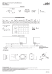
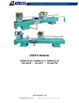
COSTRUZIONI MECCANICHE
PERSICO
S.R.L
Via Garofoli, 288 - 37057 S. Giovanni Lupatoto (VR)
Tel. +39045549535
Fax +39045545227
e.mail: [email protected] - http://www.cmpersico.com
OPERATING AND MAINTENANCE
MANUAL
THROUGHOUT FLESHING MACHINE
“SP31”
“SP34”
Manual code:
SP31istin34
INTRODUCTION
READ THE “OPERATING AND MAINTENANCE” MANUAL WITH CARE BEFORE USING
THE MACHINE. ALL OPERATING INSTRUCTIONS HAVE THE OBJECT OF PROTECTING
YOUR HEALTH AND SAFETY!
THESE INSTRUCTIONS, IN ADDITION TO SAFEGUARDING YOU AND YOUR INVESTMENT, ALSO INDICATE THE BEST PROCEDURES FOR CORRECTLY OPERATING THE
MACHINE AS CALLED FOR BY THE MANUFACTURER.
This documentation constitutes an integral part of the machine and must accompany it during all
changes of ownership or business transfers.
WHO TO CONTACT IN CASE OF BREAKDOWNS
Many technical problems can be eliminated by minor repairs. We recommend that you carefully consult this manual
before you contact our Service Department.
Turn to the manufacturer whenever the breakdown or malfunction cannot be solved.
MANUFACTURER’S DATA
Costruzioni Meccaniche Persico S.r.l.
Via Garofoli, n.288
37057 S. Giovanni Lupatoto (Verona) ITALIA
Partita IVA: 0154192 023 5
http://www.cmpersico.com
e-mail: [email protected]
Page
2
Manual code:
SP31istin34
CE statement of compliance
S. Giovanni Lupatoto
Manufacturer:
Costruzioni Meccaniche Persico S.r.l.
Via Garofoli, 288
37057 S.Giovanni Lupatoto (VR) - Italia
P. I.V.A.: 01541920235
Person in charge to keep
the technical file :
Alfredo Nieri
Via Garofoli, 288
37057 S.Giovanni Lupatoto (VR) - Italia
States under its own responsibility that the new machine
Type:Fleshing machine
Model:SP31/SP34
Serial Number:
Year of manufacture:
Described as follow: “SP31/SP34” combined hydropneumatic throughout fleshing machine for
fleshing pelt and hair hides with 3100 mm / 3400 mm useful working width and complete with electric system,
differentiated fleshing device, 1 worm screw assembly, base, 1 platform assembly, accessories.
Complies with the provisions of the European Community directives given in the publications:
· Directive 2006/42/CE
· Directive 2006/95/CE
· Directive 2004/108/CE
Legal representative of the firm specified as manufacturer:
Costruzioni Meccaniche Persico Srl
Alfredo Nieri
Page
3
Manual code:
SP31istin34
PROGRESSIVE AND ANALYTICAL TABLE OF CONTENTS
INTRODUCTION..........................................................................................................................page 02
WHO TO CONTACT IN CASE OF BREAKDOWNS ...................................................................page 02
MANUFACTURER’S DATA .........................................................................................................page 02
STRUCTURE OF THE MANUAL ................................................................................................page 05
1 - GENERAL STANDARDS AND WARNINGS .........................................................................page 05
1.1 WARNINGS ..................................................................................................................................... page 05
1.2 PRINTING CONVENTIONS............................................................................................................. page 05
2 - GENERAL INFORMATION ................................................................................................... page 05
2.1 WHAT IDENTIFIES THE MACHINE .................................................................................................page 06
2.2 WHERE THE IDENTIFICATION PLATE IS LOCATED ....................................................................page 06
2.3 GUARANTEE ...................................................................................................................................page 06
2.4 GUARANTEE DURATION ................................................................................................................page 06
2.5 EXCLUSIONS AND LIMITATIONS ...................................................................................................page 06
2.6 STATEMENT OF OBJECT AND USE OF THE MACHINE................................................................page 06
2.7 FORECAST AND NOT-FORECAST MACHINE USES ....................................................................page 10
3 - TECHNICAL DATA ................................................................................................................page 10
3.1 TECHNICAL CHARACTERISTICS ..................................................................................................page 10
4 - INSTALLATION .....................................................................................................................page 10
4.1 MACHINE PACKING AND STORAGE .............................................................................................page 10
4.2 UNPACKING ....................................................................................................................................page 11
4.3 CHECKING FOR DAMAGE .............................................................................................................page 11
4.4 MACHINE HOISTING INSTRUCTIONS .......................................................................................... page 11
4.5 HOISTING AND POSITIONING THE MACHINE..............................................................................page 11
4.6 POSITIONING ................................................................................................................................. page 11
4.7 CONNECTIONS .............................................................................................................................. page 11
4.7.1 CONNECTION TO ELECTRIC MAINS .........................................................................................page 11
4.7.2 CONNECTION TO WATER MAINS ...............................................................................................page 12
4.7.3 COMPRESSED AIR CONNECTION............................................................................................. page 12
4.7.4 CHECKS TO PERFORM BEFORE START-UP .............................................................................page 12
4.8 GENERAL SAFETY PRINCIPLES ...................................................................................................page 20
4.9 RECOMMENDATIONS .....................................................................................................................page 20
4.10 MACHINE NOISE .......................................................................................................................... page 20
4.11 RESIDUAL RISKS.......................................................................................................................... page 20
5 - OPERATING INSTRUCTIONS ..............................................................................................page 21
5.1 MAIN CONTROL BOARD ................................................................................................................page 21
5.2 OPERATING CONTROLS ............................................................................................................... page 21
5.3 SHARPENING CONTROLS ............................................................................................................ page 22
5.4 HYDRAULIC CONTROLS ............................................................................................................... page 22
5.5 PNEUMATIC CONTROLS................................................................................................................ page 23
5.6 SHARPENING THE BLADES ..........................................................................................................page 23
5.7 LIST OF ALARMS ........................................................................................................................... page 23
6 - FLESHING MACHINE START-UP ........................................................................................ page 23
6.1 MACHINE CYCLE SEQUENCES ....................................................................................................page 24
6.2 FIRST PROCESSING PHASE ........................................................................................................ page 26
6.3 SECOND PROCESSING PHASE ................................................................................................... page 26
6.4 THIRD PROCESSING PHASE ........................................................................................................page 27
6.5 FOURTH PROCESSING PHASE ....................................................................................................page 27
6.6 MONITORING AND SAFETY EQUIPMENT .................................................................................... page 28
6.6.1 CLOSURE SAFETY DEVICE ....................................................................................................... page 28
6.6.2 MACHINE ACCESS BARRIERS ...................................................................................................page 28
6.6.3 SAFETY KEY ................................................................................................................................page 28
7 - MAINTENANCE .................................................................................................................... page 28
7.1 PRECAUTIONS ...............................................................................................................................page 28
7.2. ADJUSTMENTS...............................................................................................................................page 28
7.2.1. BOLSTER POSITION AND PRESSURE ADJUSTMENTS ......................................................... page 29
7.2.1.1. UPPER BOLSTER ADJUSTMENT ...........................................................................................page 29
7.2.1.2 LOWER BOLSTER ADJUSTMENT ........................................................................................... page 29
7.2.2 OTHER BOLSTER ADJUSTMENTS ............................................................................................ page 29
7.3 LUBRICATION ................................................................................................................................. page 29
7.3.1 HYDRAULIC SYSTEM OIL AND FILTER ..................................................................................... page 29
7.4 ROUTINE PREVENTIVE MAINTENANCE SCHEDULE ................................................................. page 30
8 - REMOVAL AND REINSTALLATION OF CRITICAL COMPONENTS................................... page 30
Page
4
Manual code:
SP31istin34
8.1 POSITION AND CONVEYING ROLLER PRESSURE ADJUSTMENT ........................................... page 31
8.2 REMOVING THE UPPER BLADE ROLLER ....................................................................................page 31
8.3 REMOVING THE LOWER BLADE ROLLER ...................................................................................page 31
9 - MACHINE DISMANTLING AND DEMOLITION ....................................................................page 32
10 - DRAWINGS AND FIGURES ............................................................................................... page 32
11 - ENCLOSURES
Electrical diagram
Hydraulic diagram
Spare parts manual
Inverter’s setting manual
Page
5
Manual code:
SP31istin34
STRUCTURE OF THE MANUAL
This manual consists of eleven parts containing:
1. GENERAL STANDARDS AND WARNINGS - introductory remarks that help you understand and use the manual;
2. GENERAL INFORMATION - introductory remarks that help you identify the machine;
3. TECHNICAL DATA - information on machine characteristics;
4. INSTALLATION - notes for correctly installing the machine in the factory;
5. OPERATING INSTRUCTIONS - interface for a safe machine operation;
6. MACHINE START-UP - information on work procedures on-board the machine;
7. MAINTENANCE - tips and recommendations;
8. REMOVAL AND REINSTALLATION OF CRITICAL COMPONENTS - information on safety procedures for performing these operations;
9. MACHINE DISMANTLING AND DEMOLITION;
10. DRAWINGS AND FIGURES;
11. TECHNICAL DATA ATTACHMENTS including:
Spare parts manual;
Wiring diagram manual;
Hydraulic diagram manual.
1 - GENERAL STANDARDS AND WARNINGS
1.1 WARNINGS
This operating and maintenance manual is an integral part of technical documentation regarding the “SP31” and
“S34” throughout fleshing machine.
The manual must be kept with care and made available to all personnel involved. The manual, in harmony with the
overall machine project, has been drawn up in full compliance with European Community directives: publications No.
2006/42/EC - 2006/95/EC - 2004/108/EC.
The manual has three functions: as a tool for the machine operator, as a technical and commercial reference for the
Customer and as an in-house document for the Costruzioni Meccaniche Persico S.r.l. Company.
1.2 PRINTING CONVENTIONS
The user’s manual uses the following printing conventions:
SymbolMeaning
The notes contain important information placed outside the main text: give them your full attention.
The warning messages contain the procedures, indicated in the manual, which must be complied with to
avoid damage to the equipment.
The caution messages indicate specific procedures which must be complied with to prevent harm to the
machine operator.
2 - GENERAL INFORMATION
The following pages illustrate to the user how to identify the “SP31” or “SP34” products manufactured by Costruzioni
Meccaniche Persico S.r.l. This is particularly important in the long run to permit the manufacturer to quickly and
precisely give the customer technical information or help of any kind.
We, therefore, recommend that you do not alter or remove the information necessary for identifying the product.
2.1 WHAT IDENTIFIES THE MACHINE
The physical means of identification is the silk-screened and/or engraved and printed identification
plate that carries the information to give to Costruzioni Meccaniche Persico S.r.l. in case of need. This is the only
means recognized by the manufacturer as a valid means for identifying the product.
Page
6
Manual code:
SP31istin34
2.2 WHERE THE IDENTIFICATION PLATE IS LOCATED
The identification plate is located on the door to the electric board on the front left side of the machine (See
Figure 2).
Figure 1
Figure 2
2.3 GUARANTEE
Costruzioni Meccaniche Persico S.r.l. guarantees this machine as set forth by contract. Costruzioni Meccaniche
Persico S.r.l. replaces, under guarantee coverage, all components that are found to be defective during the guarantee
period because of evident or hidden defects in raw materials or manufacturing errors within the limits described below.
Worn or broken components must be returned to Costruzioni Meccaniche Persico S.r.l. in order to determine the
causes of the defect and be able to apply guarantee coverage to the specific problem.
The user must follow the instructions for proper machine operation and maintenance. Particular importance must be
attached to installation, start-up, lubrication, cleaning instruction and the routine maintenance schedule (chapter 7).
Failure to comply with these instructions will invalidate guarantee coverage.
The components to be replaced or repaired must be sent free to our factory in S. Giovanni Lupatoto.
Defective components must be returned free to our factory in S. Giovanni Lupatoto.
2.4 GUARANTEE DURATION
The duration of the guarantee is as set forth by the contract. This period starts from the date of shipment of the
machine.
2.5 EXCLUSIONS AND LIMITATIONS
Parts normally subject to wear are excluded. Other components such as light bulbs, fuses, etc. which have
undetermined durations are excluded from guarantee coverage.
Guarantee coverage refers exclusively to the machinery and components delivered by Costruzioni Meccaniche
Persico S.r.l. and excludes claims for consequential damages or losses.
Guarantee coverage is subject to Purchaser’s full compliance with his obligations and shall not be valid if the material
is modified or tampered with by others or if precautions for protecting the machine from operating errors have not
been adopted.
2.6 STATEMENT OF OBJECT AND USE OF THE MACHINE
“SP31” or “SP34” throughout fleshing machines are designed to process whole cowhides. The machine performs
fleshing using systems similar to traditional fleshing machines with the substantial difference that it is only necessary
to introduce the skin for the length necessary for proper conveying and the machine will then process the entire skin
without having to turn it to complete fleshing.
The skin is unloaded from the rear of the machine with the grain on top and consequently ready for any subsequent
processing by a splitting machine. “SP31” or “SP34” throughout fleshing machines have totally hydraulic drives. Use
calls for two operators on-board the machine as well as personnel at ground level to supply the skins.
The machine can be completed by several optional devices. These do not change its mode of operation or object but
permit improvement of several processing or operating characteristics.
A brief description of optional equipment follows. Refer to specific manuals for more detailed information.
Page
7
Manual code:
SP31istin34
OPTIONAL
Screw assembly - the screw assembly is installed, on request, below the fleshing rollers and consists of two stainless
steel hoppers containing a helical spiral. It conveys flesh out from the machine without using water. It is powered by a
hydraulic motor and is equipped with a hydraulic unit.
This assembly is totally independent from the machine itself and can be mounted, on request, on all machines in
place of traditional water-powered flesh discharge systems.
Flesh expulsion pump - when the screw assembly is installed the “P22” pump can also be installed.
This pump collects flesh and push it through a 120-140 mm diameter tube up to a distance of 100-150 meters.
Pneumatic skin manipulator - The “M23” manipulator conveys skins from their collection station up to the fleshing
machine for processing. It consists of two or three runways (depending on the model). Each runway consists of a
beam carrying a winch with a pneumatic clamp for hooking up the skins.
Skin manipulator support - this accessory supports the manipulator’s beams. Otherwise they must be anchored to
the ceiling. It makes it easier to move the machine about in the factory, if necessary.
Steel struts - the struts are steel bases on which the machine is anchored. They support the machine at a height
above pavement level that permits flesh to be discharged into the pump or into the collection slide. Struts also prevent
the need to build reinforced concrete walls to perform the same function. Steel struts are delivered complete of gates
connected to the safety system to prevent access below the machine during work.
Additional maintenance platforms - additional platforms consist of a set of galvanized iron catwalks around the
machine to permit safe maintenance procedures. They are delivered dismantled for shipping purposes but are all
numbered to permit easy assembly.
The following figures illustrate the various accessories available for the machine.
Complete system
Page
8
Manual code:
SP31istin34
Screw assembly equipped with a hydraulic unit
Flesh pump with hydraulic unit
Pneumatic skin manipulator with electric board
Page
9
Manual code:
SP31istin34
Pneumatic skin manipulator installed on the skin manipulator support
Steel struts
Page
10
Manual code:
SP31istin34
Additional maintenance platforms
2.7 FORECAST AND NOT-FORECAST MACHINE USES
“SP31” and “SP34” throughout fleshing machines are designed to process whole green or pelt cowhides.
Skins must have a maximum width of 3100 mm or 3400 mm depending on the model and a length that is not
less than 1200 mm.
Processing of any other material or material with unsuitable dimensions can create risk of damage to the
machinery and harm to the operator.
3 - TECHNICAL DATA
The following table gives technical characteristics for the “SP31” and “SP34” fleshing machines. Read the table with
care before performing handling and installation procedures.
3.1 TECHNICAL CHARACTERISTICS
Useful working widthmm.
3.100 3.400
Minimum length of skins to be processed
mt.
1,2
1,2
Max. variable fleshing speed mt/min 55
55
Total installed powerKw
70
80
Approximate net weightKg
20.000
21.000
Overall dimensionsmm.
6.500
6.800
Widthmm.
2.150
2.150
Heightmm.
2.750
2.750
Overall crate dimensions model S3121
mm.
2.330x7.030x2.970
Overall crate dimensions model S3421
mm.
2.330x7.330x2.970
Crate weightKg.
1.800
2.000
4 - INSTALLATION
4.1 MACHINE PACKING AND STORAGE
The machine, after factory testing, is prepared for shipment, packed and protected as agreed upon in the contract.
The machine can be shipped on truck without any packing or in a sea-packing crate. In this latter case the truck must
have a lowered bed. The machine is totally covered with a thin layer of protective product before it is packed. If the
machine will be stored in a warehouse for a long period of time it must be placed where it is protected from weather
and/or blows which could generate dangerous malfunctions or alterations.
Page
11
Manual code:
SP31istin34
In any case if storage time at the destination site will be greater than 2/3 months then the packing
should be opened and the protective film restored.
STORAGE TEMPERATURE: .................................... from -25°C to +55°C
WORKING TEMPERATURE:..................................... from 0° to +40°C
NO-CONDENSING RELATIVE HUMIDITY:............... from 5% to 90%
Inside the control junction box
4.2 UNPACKING
To unpack the machine (when it is inside packing) first remove the cover from the packing crate and then the side
walls. Be careful not to damage the machine with the tools used to unpack it.
Check that the entire machine equipment is complete and sound according to what is indicated in the packing list.
4.3 CHECKING FOR DAMAGE
ALWAYS CHECK, before doing anything else:
That no part of the machine has been subject to blows during transport and/or handling.
That no water has penetrated into the control junction box.
4.4 MACHINE HOISTING INSTRUCTIONS
Hoisting may create danger situations for exposed persons. BE SURE TO COMPLY WITH the instructions furnished
by Costruzioni Meccaniche Persico S.r.l. in this manual and to use suitable and properly checked equipment.
Hoisting personnel must be trained and authorized to use hoisting machinery and equipment.
It is the customer’s responsibility to select the hoisting equipment and the cables, chains or slings held to
be most suitable both in terms of efficiency and in terms of carrying capacity.
4.5 HOISTING AND POSITIONING THE MACHINE
When you are moving a machine that is still in its packing crate then position the sling cables at the points indicated on
the packing crate. Check the total weight of the packed machine indicated on the crate.
When you are moving a machine that has been unpacked use the two specific holes located on top of the head in
order to hoist it using the two gudgeon pins we deliver, with 75 mm. diameter and with four cables (figure 19). The
gudgeon pins must be inserted all the way into their holes.
4.6 POSITIONING
Set the machine on a solid cement base. Remember that the machine’s base has special holes for leveling and for
anchorage. If a slide and water system is used to remove flesh from the machine, then the machine must be installed
at a suitable height in order to be able to discharge the flesh at the desired distance.
If screw conveyors and an expulsion pump is used to remove flesh and to reduce water consumption to a minimum
then the machine can be installed at a lower height (1200 mm. is recommended).
Steel struts can be delivered, as shown in figures 3 and 4, to make installation easier and faster. These struts have two
sets of holes, “A” holes for anchoring the machine and “B” holes for leveling on the pavement.
These struts are installed below the machine while it is still suspended from the crane. Cement mortar must be used
to fill any cracks in the pavement when installation is completed.
The machine is equipped with a work platform and slide for exiting skins. Additional platforms with related ladders and
railings are delivered on request as shown in figure 7.
When delivery includes all this material the platforms are delivered dismantled in order to simplify transport. However
the simplicity of their design and the fact that all parts are clearly numbered makes it very simple to reassemble
them.
We strongly recommend that any trimming table or conveyor positioned near the stainless steel exiting belt
of the fleshing machine, are easy to remove, because access in that area will be required for some maintenance.
4.7 CONNECTIONS
Electrical energy, water and compressed air utilities must be prepared in advance by the customer.
4.7.1 CONNECTION TO ELECTRIC MAINS
ALWAYS CHECK, before performing any operation: that the machine’s forecast supply voltage and frequency
correspond to those of the power grid. Make sure that connection conductors are suitably sized for delivery of at least
Page
12
Manual code:
SP31istin34
80 kW of electrical power. Normally the machine is built for a 400 Volt and 50 Hz power supply. Different voltages
and frequencies can be provided on request.
A suitable magneto-thermal earth-leakage circuit breaking system, must be installed upstream from the machine
according to EC standards.
Connection to the electric grid must be done by qualified personnel. Remember that the customer is responsible for
installing the electrical supply line up to the terminal board on the machine.
Refer to figure 8 for passages for power cables.
Power conductors:
- 3 phase conductors
- 1 ground conductor
We call the customer’s attention to the need to provide all the safety conditions necessary for properly grounding
the machine.
The ground system must conform to current regulations in the country where the machine is installed and must be
checked by qualified personnel.
Turn on the door interlock switch in figure 20: light 8 in figure 21 must turn on.
All motors have preset rotation directions and are already connected to the control board. Check that the input line is
properly connected by checking the direction of rotation of the upper conveying rollers. To do this press push-button 4
in figure 21 and then push-button P7 in figure 22.
The conveying rollers must rotate so that they will pull the skin into the machine.
Follow the related instructions given in the start-up chapter in order to start the machine.
4.7.2 CONNECTION TO WATER MAINS
Connect pipe 1 in figure 27 to water mains using a 3/4¨ GAS threaded fitting.
Two handles are used to adjust water distribution to various points on the machine.
If the machine is equipped with screw evacuators for removing flesh then it only requires a minimum amount of water
to cool the oil in the hydraulic circuit.
4.7.3 COMPRESSED AIR CONNECTION
The machine must be connected to a compressed air system with a minimum constant pressure of at least 2 Bar. The
connection is a 3/8¨ GAS connection and is located at point 1 in figure 29.
The delivery rate of the compressed air system is not important: the air functions only to keep the pneumatic
bolsters pressurized.
4.7.4 CHECKS TO PERFORM BEFORE START-UP
The machine must be tested in compliance with the contract.
The following figures indicate all the overall dimensions and all dimensions held to be useful for positioning the
machine.
Page
13
Manual code:
SP31istin34
STEEL STRUTS
Figure 3
A- anchorage holes
B- leveling holes
Page
14
Manual code:
SP31istin34
SAFETY GATES
Take care to set the steel struts so that, the only gate that you can open, is under the working platform.
Figure 4
Page
15
Manual code:
SP31istin34
FLESH PUMP
Use the brackets provided to anchor the flesh pump to the steel struts, using the proper holes. It is possible to choose
the direction for the exiting flesh.
Figure 5
Page
16
Manual code:
SP31istin34
WORKING PLATFORM AND HIDE EXITING SLIDE
The working platform and slide will be delivered with the fleshing machine
Figure 6
Page
17
Manual code:
SP31istin34
COMPLETE SYSTEM
Figure 7
Page
18
Electrical
supply
Leveling plane
Leveling plane
Manual code:
SP31istin34
Figure 8
Page
19
Manual code:
SP31istin34
Figure 9
Page
20