1
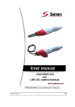
User manual
e-Jet2 equipment
SAS SAMES Technologies. 13 Chemin de Malacher 38243 Meylan Cedex
Tel. 33 (0)4 76 41 60 60 - Fax. 33 (0)4 76 41 60 90 - www.sames.com
Index revision : A
1
6428
All communication or reproduction of this document, in any form whatsoever and all use or
communication of its contents are forbidden without express written authorisation from
SAMES Technologies.
The descriptions and characteristics mentioned in this document are subject to change without prior
notice.
© SAMES Technologies 2012
WARNING : SAS Sames Technologies is registered with the Ministry of Labour as a training
institution.
Throughout the year, our company offers training courses in the operation and
maintenance of your equipment.
A catalogue is available on request. Choose from a wide range of courses to
acquire the skills or knowledge that is required to match your production
requirements and objectives.
Our training courses can be delivered at your site or in the training centre at our
Meylan head office.
Training department:
Tel. 33 (0)4 76 41 60 04
E-mail: [email protected]
SAS Sames Technologies operating manuals are written in French and translated into English, German, Spanish, Italian and
Portuguese.
The French version is deemed the official text and Sames will not be liable for the translations into other languages.
Index revision : A
2
6428
e-Jet2 equipment
1. Safety Regulations - - - - - - - - - - - - - - - - - - - - - - - - - - - - - - - - - - - - 4
2. Description - - - - - - - - - - - - - - - - - - - - - - - - - - - - - - - - - - - - - - - - - - 5
2.1. General presentation . . . . . . . . . . . . . . . . . . . . . . . . . . . . . . . . . 5
2.2. Control panel presentation . . . . . . . . . . . . . . . . . . . . . . . . . . . . 6
3. Characteristics - - - - - - - - - - - - - - - - - - - - - - - - - - - - - - - - - - - - - - - 7
3.1. General characteristics . . . . . . . . . . . . . . . . . . . . . . . . . . . . . . . 7
3.2. Pneumatic characteristics . . . . . . . . . . . . . . . . . . . . . . . . . . . . . 7
4. Operation - - - - - - - - - - - - - - - - - - - - - - - - - - - - - - - - - - - - - - - - - - - 8
4.1. With vibrating table . . . . . . . . . . . . . . . . . . . . . . . . . . . . . . . . . . 8
4.2. With fluidization tank . . . . . . . . . . . . . . . . . . . . . . . . . . . . . . . . . 8
5. Tools - - - - - - - - - - - - - - - - - - - - - - - - - - - - - - - - - - - - - - - - - - - - - - 8
6. Installation - - - - - - - - - - - - - - - - - - - - - - - - - - - - - - - - - - - - - - - - - - 9
6.1. Vibrating table version . . . . . . . . . . . . . . . . . . . . . . . . . . . . . . .
6.2. Tank version . . . . . . . . . . . . . . . . . . . . . . . . . . . . . . . . . . . . . .
6.3. Common . . . . . . . . . . . . . . . . . . . . . . . . . . . . . . . . . . . . . . . . .
6.4. Vibrating table connection . . . . . . . . . . . . . . . . . . . . . . . . . . . .
6.5. Fluidization tank connection . . . . . . . . . . . . . . . . . . . . . . . . . .
6.6. Connection of “Mach-Jet Gun” and mains plug . . . . . . . . . . . .
12
13
13
14
15
16
7. Using the equipment ”eJet2” - - - - - - - - - - - - - - - - - - - - - - - - - - - - 17
7.1. Powder coating . . . . . . . . . . . . . . . . . . . . . . . . . . . . . . . . . . . . 17
7.2. Color change . . . . . . . . . . . . . . . . . . . . . . . . . . . . . . . . . . . . . . 18
7.2.1. Vibrating table version . . . . . . . . . . . . . . . . . . . . . . . . . . . . . . . . 18
7.2.2. Tank version . . . . . . . . . . . . . . . . . . . . . . . . . . . . . . . . . . . . . . . 21
8. Maintenance - - - - - - - - - - - - - - - - - - - - - - - - - - - - - - - - - - - - - - - - 22
9. Spare parts- - - - - - - - - - - - - - - - - - - - - - - - - - - - - - - - - - - - - - - - - 23
9.1. ”e-Jet2” equipment, vibrating table version . . . . . . . . . . . . . . 23
9.1.1. Cart, vibrating table version . . . . . . . . . . . . . . . . . . . . . . . . . . . .
9.1.2. Hose and union assembly . . . . . . . . . . . . . . . . . . . . . . . . . . . . .
9.1.3. Fluidization tube . . . . . . . . . . . . . . . . . . . . . . . . . . . . . . . . . . . . .
9.1.4. Arm support . . . . . . . . . . . . . . . . . . . . . . . . . . . . . . . . . . . . . . . .
26
31
32
33
9.2. ”e-Jet2” equipment, tank version . . . . . . . . . . . . . . . . . . . . . . . 34
9.2.1. Cart, tank version . . . . . . . . . . . . . . . . . . . . . . . . . . . . . . . . . . . . 37
9.2.2. Hose and union assembly . . . . . . . . . . . . . . . . . . . . . . . . . . . . . 39
9.2.3. Tank . . . . . . . . . . . . . . . . . . . . . . . . . . . . . . . . . . . . . . . . . . . . . . 40
Index revision :
3
1. Safety Regulations
WARNING : This document contains links to the following user manuals:
• see RT Nr 6426 for the CS 130 powder pump.
• see RT Nr 6336 for the “Mach-Jet” spray gun and “CRN 457” control module.
WARNING : The ”e-Jet2” cart is designed to equip powder-paint spraying devices only.
This device may be dangerous if it is not used in compliance with the safety regulations specified
in this manual.
Operating temperature range: From 0 °C to 40 °C (32 °F to 104 °F).
• The “e-Jet2” cart and the tank must always be installed and used in areas where there is no risk
of explosion.
• It is essential to connect the ground thimble on the cart to the ground system thimble of the powdercoating installation (or powder-coating booth) to guarantee the safety of operators and correct
operation of the powder-coating equipment.
• When a fluidization tank is used, it is essential to extract fumes to an area where the powdercharged air is filtered (usually, this is the powder-coating booth).
• When a vibrating table is used, the plastic bag containing the powder must be tightly wrapped
around the plunger tube to avoid any escape of powder.
• All powder filling operations of tank must be carried out in a ventilated area designed for the
purpose and under no circumstances anywhere near the cart.
• The tank is normally used installed on the lower part of the cart. It is imperatively necessary to
connect the two banana plugs of grounding on the tank lid. The hoses of fluidization air and smoke
aspiration air also take part to connect the tank to the ground.
• If the tank is used away from the cart, it is essential to connect the tank to the ground system
electrically on the level of its lid.
• Under no circumstances may the cart be used to carry or transport loads other than the powder
tank or a powder box with a maximum weight of 30 kg on the vibrating table.
• Skin-contact or inhalation of products used with this equipment may be dangerous for
personnel (cf.: Safety sheets for products used).
Index revision : A
4
6428
2. Description
2.1. General presentation
With its compact size, the cart of the equipment ”e-Jet2” remains very stable and easy to tranport in all
circumstances thanks to its gravity center lowered, to its large back wheels and its two front directional
wheels.
The equipment ”e-Jet2” includes the CRN 457 control module with ideal height and tilted in a optimized
way for the greatest comfort of the operator. The swivelling of the screen on the operator side is done
easily thanks to the directional wheels of the cart.
The Mach-Jet gun can be hung with good height, on the two sides of the cart.
Provided with many fast couplings of air, its use and its maintenance are optimized compared to the previous generations.
Finally, numerous arrangements are planned for the various phases of use of the equipment.
Declined in two versions:
• Vibrating table: it is intended for the frequent color changes, it is then equipped with a vibrating
table, with a removable arm support and a cleaning system integrated: Fast Clean.
• Tank : it is intended for less color changes and for delicate powders which require a complete
fluidization, it is then equipped with a fluidised tank.
Equipement with tank
Equipment with vibrating table
1
2
7
3
7
4
4
5
5
8
6
6
1
2
3
4
5
6
7
8
Equipment with vibrating table
CRN 457 control module
Control panel
Arm
Powder pump
Plunger tube
Vibrating table
“Mach-Jet” spray gun
Fast Clean
Index revision : A
1
2
4
5
6
7
5
Equipment with tank
CRN 457 control module
Control panel
Powder pump
Pump (fume extraction)
Tank
“Mach-Jet” spray gun
6428
2.2. Control panel presentation
2
1
Reference
1
2
Index revision : A
Function
Fume-extraction pressure adjustment and reading
(tank)
Vibrator supply pressure adjustment and reading
(vibrating table)
Fluidization pressure adjustment and reading (tank
or plunger tube)
6
6428
3. Characteristics
3.1. General characteristics
The cart structure is designed to receive:
• A box with a maxi. weight 30 kg of powder placed in a tilted position on a vibrating table.
• A tank with a capacity of approximately 35 litres of fluidised powder.
”e-Jet2” cart dimensions (HxLxW)
Approximate weight (without powder)
1,220 x 480 x 770 mm
40 kg.
3.2. Pneumatic characteristics
Characteristics of the compressed-air supply according to standard NF ISO 8573-1:
Maximum dew point at 6 bar (90 psi)
Maximum particle-size of solid pollutants
Maximum oil concentration
Class 4, i.e. +3°C (38°F)
Class 3, i.e. 5 µm.
Class 1, i.e. 0.01 mg/m03 *
Maximum concentration of solid pollutants
Class 3, i.e. 5 mg/m03 *
* : Air flow rate values are given for a temperature of 20°C (68 °F) at atmospheric pressure of 1,013
mbar.
The filter installed on the “e-Jet2” cart is used to ensure correct operation of the equipment in the case
of accidental non-compliance with compressed-air filtering recommendations.
”e-Jet2” equipment air-supply pressure
Maximum flow rate
7 bar +/- 1 bar (*)
18 m3/h maximum
WARNING : (*) Pressure in excess of 8 bar may cause operating malfunctions.
Maximum flow rate:
Vibrating table
1 powder pump
Tank
1 powder pump + 1
fume extraction
12 m3/h maximum, of
which 0.1 m3/h for
fluidization
12 m3/h maximum, of
which 6 m3/h for
smoke aspiration
6 m3/h maximum
6 m3/h maximum
Air flow rate supplied by
CRN 457 control module
“Fluidization-air,” vibrator-air supply or fume
extraction air-flow rate
Powder “driving” air flow rate
Index revision : A
7
6428
4. Operation
4.1. With vibrating table
The powdered paint remains in its original box with a weight of approximately 30kg. The box is placed
on the vibrating table.
The vibrator vibrates the table and enables the fluidization head to reach the bottom of the powder box.
The operation of the vibrator is activated by action on the spray gun trigger. The fluidization nozzle,
supplied with compressed air, “fluidises” the powdered paint.
The powdered paint, thus fluidised, is then driven by an air jet from the powder pump to the spray gun
to which it is connected by a powder-carrying hose.
4.2. With fluidization tank
The powder contained in the tank with a capacity of approximately 35l useful or 20kg of fluidised powder,
is fluidised by an upward flow of air, distributed evenly by a porous plate located at the bottom of the tank.
The powdered paint, thus fluidised, is then driven by an air jet from the powder pump to the spray gun
to which it is connected by a powder-carrying hose. An additional pump is planned for the aspiration of
smokes generated by the fluidization of the powder.
5. Tools
No specific tools.
Index revision : A
8
6428
6. Installation
The cart is made in two parts, a base plate and a high structure.
• Step 1: Install the structure on the base plate
while having previously removed the two
screws, washers and nuts located on the base
plate.
Steps 1 and 2
• Step 2: Maintain these two parts using the two
screws, washers and nuts.
Sufficiently tighten in order to eliminate the
clearance between the structure and the base
plate without deforming the tubular elements.
Vibrating table
version
Step 3
• Step 3: Connect the main air supply hose to
the filter while passing it previously into the
guide tube.
Into the second guide tube, pass the air supply
hose of the vibrator (vibrating table version), or
the tank fluidization air hose (tank version),
and connect to the regulator corresponding.
Tank
version
Index revision : A
9
6428
• Step 4: Secure the CRN 457 control module on
the cart.
Center the screen of the module to the access
window et screw the module by its front face
using the four selftapping screws. The module
must be flushed.
Nota: The security and the remaining into
position of the module are done using the
four screws, washers and 1/4 turn nut and
an allen wrench.
Equip previously the four provided screws with
washers and 1/4 turn nut (attention: 1/4 turn
thread nut must be fitted flushed and in the
direction indicated to ensure its function; a
locating device on the cart allows to check if the
directory of nut fitting has to be respected).
Put in place the 1/4 turn nut on the screw in the
grooves of the CRN 457 box, the flat washers
being placed outside,
and move the screw at the level of the most narrow part of the print .
Tighten strongly using an allen wrench.
Check visually that the 1/4 turn nut is placed
perpendicular to the groove of the CRN 457.
Index revision : A
10
6428
• Step 5: Connect the ground cable (length: 5m)
to the grounding screw located on the side of
the cart. The other end of the ground cable has
to be imperatively connected to a part of the
booth electrically connected to the ground .
• Step 6: Connect the 220V main power cable
to the back of the CRN457 (1) (see § 6.6 page
16).
Connect the CRN457 to the ground on its
ground screw via the grounf thimble (2).
• Step 7: Connect the main pneumatic supply
union of the CRN457 (3).
Connect the pneumatic output auxiliary which
supplies the regulators to th yellow hose (4).
• Step 8: The red (air injection supply) and blue
(air dilution supply) hoses included in the hose
and union assembly provided with the cart must
be connected to the outputs of the CRN457 (5);
these two hoses as theirs quick unions must
pass by the passage of cable.
5
3
4
1
2
Ensure the positioning of these hoses in the
passage designed for this purpose using the
velcro band provided.
Index revision : A
11
6428
6.1. Vibrating table version
• Step 1: Install the arm support on the axis of the
cart.
The arm must follow the lead angle of the
vibrating table.
Step 1
• Step 2: Place the plunger tube in the arm support and install the powder pump on the
plunger tube.
• Step 3: Connect the powder pump.
The black polyurethane anti static hose is connected right side of the cart on the plunger tube
via its quick union to the output of the
corresponding regulator.
Ensure the positioning of the hose in the passage designed for this purpose using the velcro
band provided.
Index revision : A
12
Step 2
Step 3
6428
6.2. Tank version
• Step 1: Install the tank on the base plate between the centering studs.
• Step 2: Put in place the powder aspiration tube on the base of the lid, right side.
Fit the pump base without tube on the left side of the lid.
• Step 3: Install the CS130 powder pump (pump with two unions) on the right side of the tank and
the CS130 air pump (one union) on the left side.
• Step 4: Connect the lid of the tank to the ground thimble of the body and to the the thimble of the
ground strip of the cart located on the front face. It must pass through the opening designed for
this purpose so that it remains always visible.
• Step 5: Connect the quick union of fluidization air supply (black polyurethane anti static hose) at
the bottom of the tank.
The black polyurethane anti static hose of air pump supply (smoke aspiration) is connected to the
left on the cart on the air pump side injection via the quick union and on the output of the
corresponding regulator; the hose must pass by the cable passage designed for this
purpose.
Ensure the positioning of this hose using the velcro band provided.
6.3. Common
For the two versions:
• Pass the low voltage plug on the cart, connect it (see § 6.6 page 16), install the spray gun on one
of the two fixing hooks
• Roll up the low voltage cable and the powder tube assembly et tuyau poudre back side of the cart
on the roller designed for this purpose.
• Connect the powder tube between the pump and the spray gun and attach the low voltage cable
by beginning towards the spray gun using the velcro bands
The equipment is ready to operate.
Index revision : A
13
6428
6.4. Vibrating table connection
1
2
1
2
3
4
5
4
7
6
Reference
1
2
3
4
5
6
7
Index revision : A
5
Hose name
Injection air powder pump
Dilution air powder pump
General air supply
Regulator air suply
Fluidization air
Vibrator air supply
Fast Clean air supply
Hose characteristics
Red Polyurethane hose, dia: 8 mm
Blue Polyurethane hose, dia: 6 mm
Blue Polyurethane hose, dia.: 10 mm
Yellow Polyurethane hose, dia.: 8 mm
Black anti-static hose - dia: 8 mm
Blue Polyurethane hose, dia.: 8 mm
Blue Polyurethane hose, dia.: 8 mm
14
6428
6.5. Fluidization tank connection
1
2
1
2
3
4
5
6
Reference
1
2
3
4
5
6
Hose name
Injection air powder pump
Dilution air powder pump
General air supply
Regulator air suply
Fume extraction air supply
Fluidization air
Index revision : A
Hose characteristics
Red Polyurethane hose, dia: 8 mm
Blue Polyurethane hose, dia: 6 mm
Blue Polyurethane hose, dia:10 mm
Yellow Polyurethane hose, dia:: 8 mm
Black anti-static hose - dia: 8 mm
Black anti-static hose - dia: 8 mm
15
6428
6.6. Connection of “Mach-Jet Gun” and mains plug
Connect the spray gun to plug “A” on the back of the control module (see RT Nr 6336).
WARNING : To avoid damaging the plug, make sure that the spray gun positioning pin is
opposite the positioning pin on the CRN 457 base plate.
The plug is locked by pushing it into the socket; comply with positioning pins: The flat on the spray gun
cable plug must be at the top, a “click” must be heard. The click indicates that the plug is correctly
locked in position.
The plug is unlocked by pulling it out of the socket.
.
Flat
Positioning pins
The mains power cable is connected to the back of the CRN 457 module (see figure below). It is
imperative to check that the plug sector is connected to the ground.
Mains power cable
Plug “A” for the
spray gun
Index revision : A
16
6428
7. Using the equipment ”eJet2”
7.1. Powder coating
The equipment has previously been installed according to the safety rules (see § 1 page 4) and the
instructions indicated (see § 6 page 9), follow the steps described below:
• Step 1: Connect the ground cable of the cart to a conducting and connected ground part of the
application booth; the ground potential must be equal to the potential of the part to be painted.
• Step 2: Supply electrically and pneumatically the equipment.
• Step 3: Place an open powder box on the vibrating table or fill the tank with powder.
• Step 4: Put in operation the CRN 457 control module (see RT Nr 6336) (switch located in the back
of the module). Configure the CRN 457 control module (see RT Nr 6336), operation with vibrating
table or tank.
• Step 5: Choose the type of needle and select on the spray gun or on the control module the suitable high voltage charcteristic.
• Step 6: Choisir au pistolet ou à l’écran un débit poudre.
• Step 7: Direct the needle of the spray gun towards the booth and the part to be painted and
activate the trigger; adjust the regulator of the vibrator (recommended pressure between 1 and 3
bar maximum) and the fluidization (pressure approximately of about 0,2 bar and 2 bar) of the
plunger tube for the vibrating table version and the regulator of smoke aspiration and tank fluidization for the tank version.
• Step 8: Wrap the plastic bag containing the powder around the plunger tube (see § 1 page 4).
• Step 9: (see RT Nr 6336) Adjust the required powder flow rate on the spray gun or on the control
module.
Note: For tank version only, after releasing the spray gun trigger, the smoke aspiration and the
fluidization systems are supplied with air approximately 30 minutes.
Index revision : A
17
6428
7.2. Color change
7.2.1. Vibrating table version
• Step 1: Extract the fluidization tube from the
box by leaving it in the arm support and swivel
the arm support on the outside of the cart.
• Step 2: Place the spray gun in the directory of
the ventilated booth.
• Step 3: Select the cleaning mode either from
the spray gun or from the control module.
Activate the cleaning mode to the screen.
Index revision : A
18
6428
• Step 4: Once the emptied hose, the cleaning
mode remaining activate, take out the fluidization tube equipped with the pump and connect
the bottom of the tube on the Fast-Clean.
• Step 5: Press several time in a prolonged way
until there is no more powder in the spray gun
needle. The whole of the paint circuit is rinsed.
• Step 6: Disactivate the cleaning mode to the
screen. Disconnect the pump from the fluidization tube and leave the pump connected on the
cart.
• Step 7: Take down the arm support from the
cart then clean the arm support as well as the
outside of the tube of fluidization into the booth
using an air blower assembly.
• Step 8: Remove the powder box and install the
box of following color.
• Step 9: Re-install the arm, the fluidization tube,
the pump and plunge the arm in the new color.
Index revision : A
19
6428
Summary:
Fluidization Tube in
the powder box
Color 1
Color 2
Fluidization Tube out
of powder box
Entry/Exit the cleaning
mode (from the spray
gun or the control
module)
Activate / Disactivate
the cleaning mode
(from the control
module)
Action Fast Clean
Blowing the outside of
the fluidization tube
and the arm
WARNING : Not disconnect the supply as well as the unions from the pump during the cleaning
mode activated.
Index revision : A
20
6428
7.2.2. Tank version
• Step 1: Disconnect the pumps from the tank.
• Step 2: Disconnect the ground thimbles from the lid.
• Step 3: Disconnect the fluidizaton air supply from the tank.
• Step 4: Remove the lid equipped with its plunger tube.
• Step 5: Empty the tank.
• Step 6: Clean using an air blower assembly then a clean rag, the lid, the plunger tube, the tank
body and the porous plate.
• Step 7: If necessary, disassemble the low part of the tank by actuating the flange for a separate
and complete cleaning of the porous palte and its seal.
• Step 8: Place the spray gun in the directory of the ventilated booth.
• Step 9: Select the cleaning mode either from the spray gun or from the control module.
Activate the cleaning mode to the screen.
• Step 10: Disactivate the cleaning mode to the screen.
• Step 11: With an air blower assembly, clean the air and powder pumps as well as the hoses associated.
• Step 12: Re-install the assembly.
• Step 13: Fill the tank with a new color passing through the access traps of the lid.
Index revision : A
21
6428
8. Maintenance
WARNING : Cleaning operations must only be carried out using compressed air (maximum
pressure: 2.5 bar) (an air blower can be fitted to the cart as an option) and a wet cloth. Neither
water nor solvents must be used to clean the equipment (spray gun and control module). The
equipment must be cleaned at the end of each shift.
• Check regularly the air filter cartridge replace if necessary.
• If there is water or oil in the filter, dump the bowl and check the air dryer or oil remover in the
installation. To dump the bowl, unscrew the black plastic part located underneath the filter bowl.
Index revision : A
22
6428
9. Spare parts
9.1. ”e-Jet2” equipment, vibrating table version
1
2
8
3
7
4
5
6
Index revision : A
23
6428
Europe version
Description
Qty
Sale
unit
Maintenance
level for Spare
part (*)
910014683
e-Jet2 equipped with vibrating table 6m
1
1
3
910014684
e-Jet2 equipped with vibrating table
12m
1
1
3
1
-
Cart (see § 9.1.1 page 26)
1
-
-
2
1523297
1
1
3
3
910014736
1
1
2
4
910013775
Powder pump (see RT Nr 6426)
1
1
3
5
910013650
Arm support (see § 9.1.4 page 33)
1
1
3
6
910013651
Fluidization Tube (see § 9.1.3 page 32)
1
1
3
1
1
3
1
1
3
1
1
3
Item
Part Number
1524463
7
1524463-12
8
910015302
CRN 457 control module
(see RT Nr 6336)
Hose and union assembly
(see § 9.1.2 page 31)
“Mach-Jet Gun” spray gun
(see RT Nr 6336)
“Mach-Jet Gun” spray gun
(see RT Nr 6336)
CRN 457 securing kit on cart
Not shown
E4PCAL206
Main power cable 10A 250V
1
1
3
842635
5-metre ground cable, thimble dia.: 6
1
1
3
(*)
Level 1: Standard preventive maintenance
Level 2: Corrective maintenance
Level 3: Exceptional maintenance
Index revision : A
24
6428
”US” Version
Item
Part Number
910014687
910014688
Description
Qty
Sale
unit
Maintenance
level for Spare
part (*)
e-Jet2 equipped with vibrating table 6m
1
1
3
1
1
3
1
-
-
1
1
3
1
1
2
1
1
3
e-Jet2 equipped with vibrating table
12m
Cart (see § 9.1.1 page 26)
1
-
2
1523297
3
910014736
4
910013775
CRN 457 control module
(see RT Nr 6336)
Hose and union assembly
(see § 9.1.2 page 31)
Powder pump (see RT Nr 6426)
5
910013650
Arm support (see § 9.1.4 page 33)
1
1
3
6
910013651
Fluidizing Tube (see § 9.1.3 page 32)
1
1
3
1
1
3
1
1
3
1524463
7
1524463-12
8
“Mach-Jet Gun” spray gun
(see RT Nr 6336)
“Mach-Jet Gun” spray gun
(see RT Nr 6336)
910015302
CRN 457 securing kit on e-Jet2 cart
1
1
3
E4PCAL459
842635
F6RLHG362
Not shown
”US” Main power cable
5-metre ground cable, thimble dia.: 6
Conical adapter G 1/4-NPT 1/4
1
1
1
1
1
1
3
3
3
(*)
Level 1: Standard preventive maintenance
Level 2: Corrective maintenance
Level 3: Exceptional maintenance
Index revision : A
25
6428
9.1.1. Cart, vibrating table version
1
1
12 13
10
11
14
13
14
14
15
9
8
6
7
2
3
5
4
22
18
16
19
20
11
21
10
Index revision : A
26
23
DES05504
17
6428
24
25
31
25
26
29
30
30
Index revision : A
28
29
27
27
6428
Qty
Sale
unit
Maintenance
level for Spare
part (*)
1
2
1
1
1
1
1
3
3
3
1
4
4
1
1
1
1
1
1
1
3
3
3
3
3
1
1
2
2
2
2
1
1
1
1
1
1
3
3
3
3
3
3
2
2
1
1
3
3
2
2
2
1
1
1
3
3
3
4
4
1
1
3
3
X7CVHA228
X7CEHU006
X7DDZU006
EU9000835
Vibrating table (see § 9.1.1.1 page 29)
Pressure gauge 4 bar
Dual banjo fitting
Quick release reducer
Fast clean and securing
Fast clean (see § 9.1.1.2 page 30)
Zinc coated Chc M6 x 16 screw
Fan washer Dia.: 6
Zinc coated H M8 x 16 screw
Fan washer Dia.: 8
Rollers and securing
Pivoting roller
Conductive pivoting roller
Black Chc M10 x 30 screw
Fan washer Dia.:10
Zinc coated Z10 U washer
Zinc coated M 10 U nylstop nut
Securing of arm support on cart
Fan washer Dia.: 8
Zinc coated Chc M8 x20 screw
Securing high and low parts
Zinc coated Chc M8 x 40 screw
Zinc coated M 8 U nylstop nut
Zinc coated Z 8 U washer
Securing back cover
Zinc coated Chc M6 x16 screw
Fan washer Dia:6
Ground screw on cart
Brass H M6 x 30 screw
Brass H M6 U nut
Brass Z6 U washer
Fan washer Dia:6
1
2
3
1
1
1
1
1
3
3
3
3
910014956
910014955
F6RLCS016
910014735
F6RLCS008
F6RLUS225
160000152
F6RLTS416
F6RLDS145
Ground strip
Ground wire CRN e-Jet2
Female elbow fitting
Regulator assembly (see § 9.1.1.3 page 30)
Male elbow fitting
Male union
Filtering cartridge - 5 µm
Tee fitting
Quick release elbow fitting (back of CRN)
1
1
2
2
1
1
1
1
1
1
1
1
1
1
1
1
1
1
3
3
3
2
3
3
1
3
3
Item
Part Number
1
2
3
EU9001879
130001161
F6RPRR150
6
10
11
16
17
1527409
X3AVSY223
EU9000835
X2BVHA280
EU9000847
4
5
18
19
20
21
EU9000065
EU9000064
EU9000760
EU9000837
X2BDZU010
X2BEHS010
29
30
EU9000847
X3AVSY283
7
8
9
250000166
X2BEHS008
X2BDZU008
10
11
X3AVSY223
EU9000835
12
13
14
15
22
23
24
25
26
27
28
31
Description
(*) Level 1: Standard preventive maintenance
Level 2: Corrective maintenance
Level 3: Exceptional maintenance
Index revision : A
28
6428
9.1.1.1. Vibrating table
1
2
10
A
3
4 5
9
8
7
6
Item
Part Number
Description
Qty
Sale
unit
Maintenance
level for Spare
part (*)
-
Vibrating table
1
-
-
1
F6RLUS199
Male simple union
1
1
3
2
910014952
Ground strip
1
1
3
3
180000061
Pneumatic vibrator
1
1
2
4
X2BVHA286
White zinc coated H M 8x 35 8/8 screw
2
1
1
5
EU9000847
Zinc coated M 8 U washer
2
1
1
6
EU9000660
Chc M 6 x 10 screw
(securing screw of damper on table)
3
1
3
7
EU9000835
Fan washer Dia.:6
3
1
3
8
X2BEHS006
M6 Nylstop nut
3
1
1
9
X2BDMU006
Zinc coated M 6 U washer
3
1
1
10
EU9000355
Damper
3
1
3
EU9000835
Fan washer Dia.:6
1
1
3
X3AVSY223
Zinc coated Chc M 6 x 16 screw
1
1
3
X2BDMU006
Zinc coated M6 U washer
1
1
3
X2BEHS006
Zinc coated nylstop M6 U nut
1
1
3
A
Index revision : A
29
6428
9.1.1.2. Fast Clean
1
Item
Part Number
1
1527409
F1VPDC132
Description
Fast Clean
Distributor
Qty
Sale
unit
Maintenance
level for Spare
part (*)
1
1
1
1
3
2
Qty
Sale
unit
Maintenance
level for Spare
part (*)
2
1
1
1
1
1
1
1
1
1
2
3
3
2
3
9.1.1.3. Regulator assembly
1
4
DES05497
3
2
Item
Part Number
1
2
3
4
910014735
F6RLCS411
130001160
EU5000050
EU9000062
Description
Regulator assembly
Male elbow fitting
Swivel fitting
Porous ring
Male elbow fitting
(*)
Level 1: Standard preventive maintenance
Level 2: Corrective maintenance
Level 3: Exceptional maintenance
Index revision : A
30
6428
9.1.2. Hose and union assembly
1
2
6
3
5
4
Item
Part Number
910014736
1
2
3
4
5
6
U1GRBW197
U1GLBT152
130001142
F6RAJR026
130000624
130001143
Description
Hose and union assembly - vibrating
table
Red polyurethane hose - Dia.: 8 mm
Blue polyurethane hose - Dia.: 6 mm
Male quick union with spring
Coupling union
Black polyurethane anti static hose
Female quick union with spring
Qty
Sale
unit
Maintenance
level for Spare
part (*)
1
1
3
1.25
1.3
1
1
1.3
1
m
m
1
1
m
1
1
2
3
3
3
3
(*)
Level 1: Standard preventive maintenance
Level 2: Corrective maintenance
Level 3: Exceptional maintenance
Index revision : A
31
6428
9.1.3. Fluidization tube
1
8
2
3
7
3
2
4
5
DES05496
6
Item
Part Number
Description
Qty
Sale
unit
Maintenance
level for Spare
part (*)
910013651
Fluidization tube
1
1
3
1
J2CTPB253
O-ring black
2
1
1
2
J2FTDF341
O-ring - viton
2
1
1
3
J2FTDF177
O-ring - viton
2
1
1
4
900009302
Porous washer
1
1
1
5
J2FTDF160
O-ring - viton
1
1
1
6
900009303
Suction nozzle
1
1
2
7
EU9000855
Black washer
1
1
3
8
EU9001083
Quick release union
1
1
3
(*)
Level 1: Standard preventive maintenance
Level 2: Corrective maintenance
Level 3: Exceptional maintenance
Index revision : A
32
6428
9.1.4. Arm support
1
2
Item
Part Number
Description
Qty
Sale
unit
Maintenance
level for Spare
part (*)
910013650
Arm support
1
1
3
1
J2CTPB253
Plunger tube ring
1
1
2
2
E3RPCN036
Rilsan nut
1
1
2
(*)
Level 1: Standard preventive maintenance
Level 2: Corrective maintenance
Level 3: Exceptional maintenance
Index revision : A
33
6428
9.2. ”e-Jet2” equipment, tank version
1
2
8
3
7
4
5
6
Index revision : A
34
6428
Europe version
Item
Part Number
Description
Qty
Sale
unit
Maintenance
level for Spare
part (*)
910014685
e-Jet2 equipped with tank 6m
1
1
3
910014686
e-Jet2 equipped with tank 12m
1
1
3
1
-
Cart (see § 9.2.1 page 37)
1
-
-
2
1523297
1
1
3
3
910014737
1
1
2
4
910013775
Powder pump (see RT Nr 6426)
1
1
3
5
910014738
Tank (see § 9.2.3 page 40)
1
1
3
6
910014333
1
1
3
1
1
3
1
1
3
1524463
7
1524463-12
8
CRN 457 control module
(see RT Nr 6336)
Hose and union assembly
(see § 9.2.2 page 39)
Air pump (smoke aspiration)
(see RT Nr 6426)
“Mach-Jet Gun” spray gun
(see RT Nr 6336)
“Mach-Jet Gun” spray gun
(see RT Nr 6336)
910015302
CRN 457 securing kit on cart
1
1
3
E4PCAL206
842635
Not shown
Main power cable 10A 250V
5-metre ground cable, thimble dia.: 6
1
1
1
1
3
3
(*)
Level 1: Standard preventive maintenance
Level 2: Corrective maintenance
Level 3: Exceptional maintenance
Index revision : A
35
6428
”US” Version
Item
Part Number
Description
Qty
Sale
unit
Maintenance
level for Spare
part (*)
910014689
e-Jet2 equipped with tank 6m
1
1
3
910014690
e-Jet2 equipped with tank 12m
1
1
3
1
-
Cart (see § 9.2.1 page 37)
1
-
-
2
1523297
1
1
3
3
910014737
1
1
2
4
5
910013775
910014738
1
1
1
1
3
3
6
910014333
1
1
3
1
1
3
1
1
3
1524463
7
1524463-12
8
CRN 457 control module
(see RT Nr 6336)
Hose and union assembly
(see § 9.2.2 page 39)
Powder pump (see RT Nr 6426)
Tank (see § 9.2.3 page 40)
Air pump (smoke aspiration)
(see RT Nr 6426)
“Mach-Jet Gun” spray gun
(see RT Nr 6336)
“Mach-Jet Gun” spray gun
(see RT Nr 6336)
910015302
CRN 457 securing kit on cart
1
1
3
E4PCAL459
842635
F6RLHG362
Not shown
US Main power cable
5-metre ground cable, thimble dia.: 6
Conical adapter
1
1
1
1
1
1
3
3
3
(*)
Level 1: Standard preventive maintenance
Level 2: Corrective maintenance
Level 3: Exceptional maintenance
Index revision : A
36
6428
9.2.1. Cart, tank version
1
17
16
15
14
18
17 18
19
18
2
22
3
21
20
4
5
8
6
10
11
7
12
9
23
13
24
25
26
27
30
28
29
Index revision : A
37
DES05506
26
6428
Item
Part Number
1
2
3
4
5
6
7
EU9001879
910015323
F6RLCS204
EU9000563
EU9001915
X4KDMU005
X2BEHS005
8
9
10
11
12
13
EU9000064
EU9000065
EU9000760
EU9000837
X2BDZU010
X2BEHS010
14
15
X3AVSY223
EU9000835
16
17
18
19
X7CVHA228
X7CEHU006
X7DDZU006
EU9000835
20
21
22
250000166
X2BEHS008
X2BDZU008
23
24
25
910014956
910014955
F6RLCS016
26
910014735
27
28
29
30
-
F6RLCS008
F6RLUS225
160000152
F6RLTS416
F6RLDS145
F6RAJR026
Qty
Sale
unit
Maintenance
level for
Spare part
(*)
Pressure gauge 4 bars
Ground strip
Elbow union
HC M5 x 20 screw
Positioning stud
Stainless steel M5 U washer
M5 nylstop nut
Rollers and securing
Conductive pivoting roller
Pivoting roller
Black Chc M10 x 30 screw
Fan washer Dia.:10
Zinc coated Z10 U washer
Zinc coated M 10 U nylstop nut
Securing back cover
Zinc coated Chc M6 x16 screw
Fan washer Dia:6
Ground screw on cart
Brass H M6 x 30 screw
Brass H M6 U nut
Brass Z6 U washer
Fan washer Dia:6
Securing high and low parts
Zinc coated Chc M8 x 40 screw
Zinc coated M 8 U nylstop nut
Zinc coated Z 8 U washer
2
1
1
3
3
3
3
1
1
1
1
1
1
1
3
3
3
3
2
3
3
1
1
2
2
2
2
1
1
1
1
1
1
3
3
3
3
3
3
4
4
1
1
3
3
1
2
3
1
1
1
1
1
3
3
3
3
2
2
2
1
1
1
3
3
3
Ground strip
Ground wire CRN e-Jet2
Female elbow fitting
Regulator assembly
(see § 9.1.1.3 page 30)
Male elbow fitting
Male union
Filtering cartridge - 5 µm
Tee fitting
Quick release elbow fitting (back of CRN)
Coupling union 8 mm
1
1
2
1
1
1
3
3
3
2
1
2
1
1
1
1
1
1
1
1
1
1
1
1
3
3
1
3
3
3
Description
(*)
Level 1: Standard preventive maintenance
Level 2: Corrective maintenance
Level 3: Exceptional maintenance
Index revision : A
38
6428
9.2.2. Hose and union assembly
1
5
2
3
3
4
Item
Part Number
Description
Qty
Sale
unit
Maintenance
level for Spare
part (*)
1
1
3
910014737
Hose and union assembly - tank
1
U1GRBW197
Red polyurethane hose - Dia.: 8 mm
0,7
m
1
2
U1GLBT152
Blue polyurethane hose - Dia.: 6 mm
0,7
m
2
3
130001143
Female quick union with spring
2
1
3
4
130001142
Male quick union with spring
1
1
3
5
130000624
Black polyurethane anti static hose
1,3
m
3
(*)
Level 1: Standard preventive maintenance
Level 2: Corrective maintenance
Level 3: Exceptional maintenance
Index revision : A
39
6428
9.2.3. Tank
Item
Part Number
Description
Qty
Sale
unit
Maintenance
level for Spare
part (*)
910014738
Tank
1
1
3
EU75000006
Porous plate
1
1
1
EU75000033
Fluidizing seal
1
1
1
EU9000852
White ring 1/8
1
1
2
EU9001083
Quick union 1/8
1
1
3
EU9000189
Elbow union 1/8 BSP
1
1
3
EU9000113
Ground thimble
1
1
3
E4CSPR080
Blue thimble
1
1
3
130000818
Male female reduction
1
1
3
EU9000114
4 mm green banana plug
1
1
3
EU9001064
Ground strip
1
1
3
J2CTCN052
O-ring - black
2
1
3
J2CTPB253
O-ring - black
2
1
3
547866
Support tube
1
1
3
910008159
450 mm Tube for pump
1
1
3
(*)
Level 1: Standard preventive maintenance
Level 2: Corrective maintenance
Level 3: Exceptional maintenance
Index revision : A
40
6428