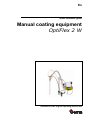
1
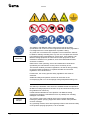
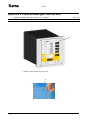
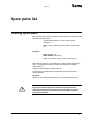
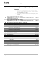
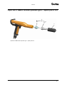
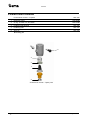
En
Quick reference guide
Manual coating equipment
OptiFlex 2 W
Translation of the original operating instructions
V 03/13
Documentation OptiFlex 2 W
© Copyright 2010 Gema Switzerland GmbH
All rights reserved.
This publication is protected by copyright. Unauthorized copying is
prohibited by law. No part of this publication may be reproduced,
photocopied, translated, stored on a retrieval system or transmitted in
any form or by any means for any purpose, neither as a whole nor
partially, without the express written consent of Gema Switzerland
GmbH.
OptiFlex, OptiTronic, OptiGun, EasyTronic, EasySelect, EasyFlow,
OptiStar, OptiSelect, OptiFlow and SuperCorona are registered
trademarks of Gema Switzerland GmbH.
OptiMatic, OptiMove, OptiMaster, OptiPlus, PowerClean, Precise Charge
Control (PCC), MultiTronic and Gematic are trademarks of Gema
Switzerland GmbH.
All other product names are trademarks or registered trademarks of their
respective holders.
Reference is made in this manual to different trademarks or registered
trademarks. Such references do not mean that the manufacturers
concerned approve of or are bound in any form by this manual. We have
endeavored to retain the preferred spelling of the trademarks, and
registered trademarks of the copyright holders.
To the best of our knowledge and belief, the information contained in this
publication was correct and valid on the date of publication. Gema
Switzerland GmbH makes no representations or warranties with respect
to the contents or use of this publication, and reserves the right to revise
this publication and make changes to its content without prior notice.
Printed in Switzerland
Gema Switzerland GmbH
Mövenstrasse 17
9015 St.Gallen
Switzerland
Phone: +41-71-313 83 00
Fax.: +41-71-313 83 83
E-Mail: [email protected]
Homepage: www.gemapowdercoating.com
V 03/13
Table of contents
General safety regulations
3
OptiFlex 2 W
9
Technical data .......................................................................................................11
Start-up ..................................................................................................................14
Initial start-up .........................................................................................................17
Operation ...............................................................................................................19
Color change .........................................................................................................25
Cleaning and maintenance....................................................................................29
Troubleshooting .....................................................................................................33
Spare parts list ......................................................................................................35
OptiFlex 2 CG09
39
Troubleshooting .....................................................................................................43
Spare parts list ......................................................................................................45
OptiFlex 2 GM03
47
Cleaning and maintenance....................................................................................51
Troubleshooting .....................................................................................................55
Spare parts list ......................................................................................................57
OptiFlow injector
68
Cleaning and maintenance....................................................................................70
Troubleshooting guide ...........................................................................................72
Spare parts list ......................................................................................................73
OptiFlex 2 W
Table of contents • 1
V 03/13
General safety regulations
This chapter sets out the fundamental safety regulations that must be
followed by the user and any third parties using OptiFlex 2 W manual
coating equipment.
These safety regulations must be read and understood in full before the
OptiFlex 2 W is put into operation.
Safety symbols (pictograms)
The following warnings with their meanings can be found in the Gema
operating instructions. The general safety precautions must also be
followed as well as the regulations in the operating instructions.
DANGER!
Danger due to live electricity or moving parts. Possible consequences:
death or serious injury
WARNING!
Improper use of the equipment could damage the machine or cause it to
malfunction. Possible consequences: light injuries or damage to the
equipment
INFORMATION!
Useful tips and other information
OptiFlex 2 W
• 3
V 03/13
The OptiFlex 2 W Manual coating equipment is built to the latest
specification and conforms to the recognized technical safety regulations.
It is designed for the normal application of powder coating.
General
information
Any other use is considered non-compliant. The manufacturer shall not
be liable for damage resulting from any such non-compliant use and the
user shall bear sole responsibility for such actions. If the OptiFlex 2 W
Manual coating equipment is to be used for other purposes or other
substances outside of our guidelines, then Gema Switzerland GmbH
should be consulted.
Observance of the operating, service and maintenance instructions
specified by the manufacturer is also part of conformity of use.
The relevant accident prevention regulations, as well as other generally
recognized safety regulations, occupational health and structural
regulations are to be observed.
Furthermore, the country-specific safety regulations also must be
observed.
Additional safety and operation notices can be found on the
accompanying CD or on the homepage www.gemapowdercoating.com.
The start-up is forbidden until it has been established that the OptiFlex 2
W Manual coating equipment has been set up and wired according to the
EU guidelines for machinery.
Unauthorized modifications to the OptiFlex 2 W Manual coating
equipment exempts the manufacturer from any liability from resulting
damages or accidents.
General
dangers
The operator must ensure that all users have received appropriate
training for powder spraying equipment and are aware of the possible
sources of danger.
Any operating method, which will negatively influence the technical safety
of the powder spraying equipment, is to be avoided.
4 •
OptiFlex 2 W
V 03/13
For your own safety, only use accessories and attachments listed in the
operating instructions. The use of other parts can lead to risk of injury.
Only original Gema spare parts should be used!
Repairs must only be carried out by specialists or by authorized Gema
service centers. Unauthorized conversions and modifications can lead to
injuries and damage to the equipment and invalidate the Gema
Switzerland GmbH guarantee.
The connecting cables between the control unit and the spray gun must
be installed so as to eliminate the possibility of damage during the
operation. Safety precautions specified by local legislation must be
observed!
The plug connections between the powder spraying equipment and the
mains should only be removed when the power supply is switched off.
Electrical
danger
All maintenance activities must take place when the powder spraying
equipment is switched off.
The powder coating equipment may not be switched on until the booth is
in operation. If the booth stops, the powder coating device must switch off
too.
The control units for the spray guns must be installed and used in zone
22. Spray guns are allowed in zone 21.
Only original Gema OEM parts are guaranteed to maintain the explosion
protection rating. If damages occur related to the use of spare parts from
other manufacturers, all relevant warranty or compensation claims are
void!
Explosion hazard
Conditions leading to dangerous levels of dust concentration in the
powder spraying booths or in the powder spraying areas must be
avoided. There must be sufficient technical ventilation available, to
prevent a dust concentration of greater than 50% of the lower explosion
limit (UEG = max. permissible powder/air concentration). If the UEG is
not known, then a value of 10 g/m³ should be considered (see EN
50177).
All unauthorized conversions and modifications to the electrostatic
spraying equipment are forbidden for safety reasons.
The safety devices may not be dismantled or put out of operation.
Mandatory operational and workplace notices from the operating
company must be written in a comprehensible manner in the language of
equipment operators and posted in a suitable place.
Powder lying on the floor around the powder spraying equipment is a
potentially dangerous source of slipping. Booths may be entered only in
the places designed for this purpose.
Slip hazard
OptiFlex 2 W
• 5
V 03/13
Static charges
Static charges can have the following consequences: Charges to people,
electric shocks, sparking. Proper grounding must be in place to prevent
objects from becoming charged.
Grounding
All electrically conductive parts found within 5 meters around each booth
opening, and in particularly the objects to be coated, must be grounded.
The grounding resistance of each object must amount to maximally 1
MOhm. This resistance must be checked/tested regularly when starting
work.
Observe the
grounding
regulations
The condition of the work piece attachments, as well as the hangers,
must guarantee that the work pieces remain grounded. The appropriate
measuring devices must be kept ready in the workplace, in order to
check the grounding.
The floor of the coating area must conduct electricity (normal concrete is
generally conductive).
The supplied grounding cable (green/yellow) must be connected to the
grounding screw of the electrostatic manual powder coating equipment.
The grounding cable must have a good metallic connection with the
coating booth, the recovery unit and the conveyor chain, respectively with
the suspension arrangement of the objects.
Smoking and open flames are forbidden in the entire plant area! No work
that could potentially produce sparks is allowed!
Fire and smoke
prohibition
6 •
OptiFlex 2 W
V 03/13
The stay for persons
with cardiac
pacemakers is
forbidden
Photographing with
flashlight is
forbidden
As a general rule for all powder spraying installations, persons with
pacemakers should never enter high voltage areas or areas with
electromagnetic fields. Persons with pacemakers should not enter areas
with powder spraying installations!
Photographing with flashlight can lead to unnecessary releases and/or
disconnections by safety devices.
Disconnect the plugs before the machines are opened for maintenance
or repair.
Disconnect from
mains before
maintenance works
take place
The plug connections between the powder spraying equipment and the
mains should only be removed when the power supply is switched off.
As far as it is necessary, the operating firm must ensure that the
operating personnel wear protective clothing (e.g. facemasks).
A dust mask corresponding to filter class FFP2 at minimum must be worn
during any cleaning work.
The operating personnel must wear electrically conductive, steel-toe
footwear (e.g. leather soles).
The operating personnel should hold the gun with bare hands. If gloves
are worn, these must also conduct electricity.
These general safety regulations must
be read and understood in all cases
prior to start-up!
OptiFlex 2 W
• 7
V 03/13
OptiFlex 2 W
Note:
For further information, see the corresponding operating manual,
which can be found on the accompanying CD.
Structure
12
11
3
2
13
1
5
14
10
4
OptiFlex 2 W manual coating equipment - Structure
OptiFlex 2 W
1 OptiFlex 2 CG09 control unit
10 Filter unit
2 OptiFlex 2 GM03 manual powder gun
11 Gun holder
3 OptiFlow injector
12 Hose holder
4 Wall bracket
13 PowerClean module
5 Suction tube
14 Shelf
• 9
V 03/13
Scope of delivery
10 •
-
OptiFlex 2 CG09 control unit in a metal case with power
supply cable
-
Wall bracket with gun/hose holder filter unit
-
Suction tube
-
plug-in OptiFlow injector
-
OptiFlex 2 CM03 manual powder gun with gun cable,
powder hose, rinsing air hose and standard nozzle set
(For more on this, see the operating manual for the
OptiFlex 2 CM03 manual powder gun)
-
Pneumatic hoses for conveying air (red), supplementary
air (black), fluidizing air (black) and rinsing air (black)
-
Operating manual
-
Short instructions
OptiFlex 2 W
V 03/13
Technical data
OptiFlex 2 W
Connectable guns
OptiFlex 2 F
OptiFlex 2 GM03
connectable
yes
Warning:
The OptiFlex F manual coating equipment can only be used with the
specified gun type!
Electrical data
OptiFlex 2 W
Nominal input voltage
Frequency
Connected load
50 -60 Hz
40 VA
Nominal output voltage (to the gun)
eff.10 V
Nominal output current (to the gun)
max. 1.2 A
Connection and output for vibrator (on Aux
output)
Connection for rinsing function (valve)
110/230 VAC
max. 100 W
24 VDC
max. 3 W
Temperature range
0 °C - +40 °C
(+32 °F - +104 °F)
Max. surface temperature
100 °C (+212 °F)
Approvals
OptiFlex 2 W
100-240 VAC
II 3 D IP54 100 °C
• 11
V 03/13
Pneumatic data
OptiFlex 2 W
Max. input pressure
10 bar
Min. input pressure
6 bar
Input pressure (Dynamic based on pressure
regulator setting)
5.5 bar / 80 psi
Max. water vapor content of the compressed
air
1.3 g/m³
Max. oil vapor content of the compressed air
0.1 mg/m³
Max. compressed air consumption
8 Nm³/h
Dimensions
OptiFlex 2 W
Width
333 mm
Depth
460 mm
Height
697 mm
Weight
13 kg
Processible powders
OptiFlex 2 W
Plastic powder
yes
Metallic powder
yes
Enamel powder
no
Powder output (guide values)
General conditions for the OptiFlow Injector
Powder type
Powder hose length (m)
6
Powder hose Ø (mm)
10
Powder hose type
POE with guide strips
Input pressure (bar)
5,5
Conveying air nozzle Ø (mm)
1,6
Correction value C0
12 •
Epoxy/polyester
Powder output zeroing adjustment
OptiFlex 2 W
V 03/13
Guide values for OptiFlex 2 CG09 with the OptiFlow IG06
injector
All values in these tables are guide values. Differing environmental
conditions, wear and different powder types can affect the table values.
3 Nm³/h
Total air
4 Nm³/h
5 Nm³/h
Powder output (g/min)
Powder output
(%)
20
40
60
80
100
85
150
210
270
300
100
185
255
320
360
120
210
280
350
395
Air flow rates
The total air consists of conveying air and supplementary air, in relation
to the selected powder quantity (in %). As a result the total air volume is
maintained constant.
OptiFlex 2 CG09
Range
Factory
setting
Flow rate - fluidizing air
- OptiFlex F (without AirMover air
requirements)
0-5.0 Nm³/h
1.0 Nm³/h
Electrode rinsing air flow rate
0-3.0 Nm³/h
0.1 Nm³/h
Flow rate total air (at 5.5 bar)
1.8-6.5 Nm³/h
Note:
The total air consumption for the device is determined for each
device type based on the 3 configured air values (without AirMover
air value for OptiFlex F).
These values apply for an internal control pressure of 5.5 bar!
OptiFlex 2 W
• 13
V 03/13
Start-up
Connection instructions
The OptiFlex 2 W manual coating equipment must be connected in
accordance with the setup and connection instructions (Please also
review the operating instructions for the OptiFlex 2 CG09 manual gun
control unit).
Gun
Maintenance unit
5.5 bar
Injector
Airmover
PowerClean module
Fluidized
powder hopper
Connection instructions - overview
Note:
The compressed air must be free of oil and water!
14 •
OptiFlex 2 W
V 03/13
Connections
Compressed air hoses / cables
Connections – Compressed air hoses / cables
Connection
Description
1.1 Main air IN
Connection compressed air (5.5 bar / 80 PSI)
2.1 Power IN
Mains cable connection (100-240 VAC)
2.2 Aux
Vibration motor connection for OptiFlex B
2.3 Gun
Gun cable connection
2.4 Purge
Connection to rinsing module
1.5
Fluidizing air connection
1.4
Electrode rinsing air connection
1.3
Supplementary air connection
1.2
Conveying air connection
Grounding connection
Pin assignment
Power IN connection
2
PE
3
1
Neutral conductor (power supply)
2
Phase (100-240 VAC)
3
Output vibrator or stirrer
PE
Grounding PE
1
OptiFlex 2 W
• 15
V 03/13
Initial start-up
Note:
If a malfunction occurs, see the troubleshooting guide, as well as
the gun control unit operating manual!
Note:
The remainder of the start-up procedure for the OptiFlex 2 GM03
manual powder gun is explicitly described in the operating
instructions for the OptiFlex 2 CG09 manual powder gun control
unit (chapter "Initial start-up" and "Daily start-up")!
OptiFlex 2 W
• 17
V 03/13
Setting the device type
Note:
If the control unit is delivered as a integral component of an
OptiFlex apparatus, then the system parameters will have been
factory preconfigured for optimal use (For more on this, please also
see the operating instructions for the OptiFlex 2 CG09 manual gun
control unit)!
NOTE!
The manual gun control unit always starts up to the last configured
settings.
18 •
OptiFlex 2 W
V 03/13
Operation
Coating
DANGER!
During the coating process, the gun can discharge along the body
of the coating person if not held using its intended handle, which
has been grounded
- Always hold gun only by the handle!
- Do not touch any other parts of the gun!
WARNING:
If the manual equipment is not being used for coating in
conjunction with a sufficiently powerful suction unit, then the
stirred-up dust from the coating powder can cause respiratory
issues or cause a slippage/falling hazard.
- The manual equipment may only be operated in conjunction with a
sufficiently powerful suction unit (such as Gema Classic Open
booth).
1. Turn on the gun control unit with the ON key
The displays illuminate and the control unit is ready for operation
2. Place powder hopper on the mobile trolley
WARNING:
When setting the powder hopper onto the mobile trolley of the
manual equipment, the hopper/trolley zone represents a threat of
crushed toes
- Wear safety shoes with steel toecaps
3. Set the ventilation (Airmover)
a) Open the ball valve completely
b) Calibrate with the throttle valve
4. Fill in powder
a) Open the powder hoper filling cover
b) Fill with maximum 25 kg (50 l) powder or the powder must
reach to a maximum of 5-10 cm below the handles of the
powder hopper, otherwise the fluidized powder can escape
from the cover
OptiFlex 2 W
• 19
V 03/13
c) Close the filling cover of the powder hopper again
5. Set coating parameters:
6. Press the application button for the appropriate preset mode:
flat parts
complicated parts
overcoat
The arrow above the desired button lights up
OR
7. Press
program key
c) Select desired program (01-20)
d) Change coating parameters as required
Note:
Programs 01-20 are preset at the factory but can be modified at any
time, after which they are automatically stored.
Description
Presetting
Powder output
50%
Total air
4.0 Nm³/h
High voltage
80 kV
Spray current
80 μA
Electrode rinsing air
0.1 Nm³/h
Fluidizing air
0.1 Nm³/h (for OptiFlex-B and S)
8. Setting the total air volume
20 •
OptiFlex 2 W
V 03/13
correct powder cloud
too little total air
Note:
A total air volume of 4 Nm³/h and a 50% powder share are
recommended as the base values.
9. Adjust the powder output volume (e.g. according to the desired
coating thickness)
or
much powder
little powder
Note:
To achieve maximum efficiency, we recommend avoided an overly
high powder volume where possible! The standard setting of 50%
and a total air volume of 4 Nm³/h is recommended at the start. The
total air volume is thereby kept constant automatically by the
control unit.
If values are entered that the equipment cannot implement, then the
operator is informed of this by a blinking in the relevant display and
a temporary error message!
10. Setting the electrode rinsing air
a) Press the key
The second display level will be shown
b)
OptiFlex 2 W
• 21
V 03/13
approx.
0.1 Nm³/h
approx.
0.5 Nm³/h
too much electrode rinsing air
11. Setting the fluidization
a)
Press the key
The second display level will be shown
b)
c) Check the powder fluidization in the powder container
The powder fluidization in the powder containers depends on
the powder characteristics, the humidity and the ambient air
temperature. Fluidizing and vibration start by switching on
the control unit.
WARNING:
If the ventilation has been incorrectly adjusted, then the coating
powder can create a dust cloud capable of causing respiratory
problems.
- Ensure proper setting of ventilation
12. Point the gun into the booth (not at the object to be coated),
press the gun trigger and visually check the powder output
13. Check whether everything is functioning correctly
14. Coating
15. Adjust the coating parameters as necessary
16. Activate the rinsing function periodically
Note:
It prevents the bridging phenomena that can lead to short circuiting
when handling powders such as metallic powders.
In moist or tropical environments, any moisture is driven from the
injector, powder hose and powder gun.
a)
-
22 •
The LCD segments begin to move on the CG09 display
OptiFlex 2 W
V 03/13
Note:
The PowerClean function can be stopped as required using the P
key.
= automatically
= manually
b)
Procedure
Effect
- The automatic rinsing process is started
automatic
manual
- Injector, powder hose, gun and spray nozzle are purged
using compressed air
- The automated PowerClean function enables parallel
cleaning of other components, such as the fluid intake
unit, powder container, etc.
- The operator controls the number and length of the
PowerClean impulse by pressing the pistol trigger a
second time
After completion of the PowerClean procedure, the controller switches
back to coating mode.
OptiFlex 2 W
• 23
V 03/13
Color change
General information
When a color change takes place, the individual components of the
manual coating equipment must be cleaned carefully. All powder
particles of the former color must be removed during this process!
The following describes an 'extreme' color change (light to dark).
OptiFlex 2 W
1.
2.
3.
4.
5.
6.
7.
8.
• 25
V 03/13
Remove and clean the nozzle,
purge gun using air
9.
10.
11.
12.
13.
14.
15. Separate fluidized air cable
16. Remove cover, purge with compressed air and clean with a clean, dry
brush and cloth
17. Clean suction intake pipe
18. Empty remaining powder into a container
19. Vacuum up container and in particular the bottom
20. Clean container with a cloth
21. Reconstruct the powder container
22. Fill with new powder
26 •
23.
24.
25.
26.
OptiFlex 2 W
V 03/13
27.
28.
29.
30.
Shutdown
1. Release gun trigger
2. Switch off the control unit
Note:
The adjustments for high voltage, powder output, electrode rinsing
air and fluidizing remain stored!
If in disuse for several days
1. Separate from power mains
2. Clean the coating equipment (see the corresponding
operating manual)
3. Turn off the compressed air main supply
OptiFlex 2 W
• 27
V 03/13
Cleaning and maintenance
Note:
Regular and conscientious maintenance increases the service life of
the OptiFlex 2 W manual coating equipment and provides for a
longer continuous coating quality!
The parts, which are to be replaced during maintenance work, are
available as spare parts. These parts will be found in the
corresponding spare parts list!
Daily maintenance
1. Clean the injector (see therefore the user manual of the OptiFlow
injector)
2. Clean the powder gun (For more on this, please also review the
user manual for the OptiFlex 2 GM03 manual powder gun)
3. Clean the powder hose; Please also review the section "Color
change"
Weekly maintenance
1. Clean fluidizing/suction unit, injector, rinsing module and powder
gun. The fluidizing/suction unit is placed back into the powder
shortly before restarting operation
2. Check the control unit grounding connections to the coating
booth, the suspension devices of the work pieces, or the
conveyor chain
If in disuse for several days
1. Separate from power mains
2. Clean the coating equipment
3. Turn off the compressed air main supply
Powder hose rinsing
If longer downtimes take place, the powder hose has to be cleaned.
Procedure:
1. Disconnect the powder hose from the hose connection on the
injector
2. Point the gun into the booth
3. Blow through the hose manually with a compressed air gun
4. Connect the powder hose again to the hose connection on the
injector
OptiFlex 2 W
• 29
V 03/13
Cleaning
WARNING:
If no dust mask or one of an insufficient filter class is worn when
cleaning the manual equipment, then the dust that is stirred up from
the coating powder can cause respiratory problems.
- The ventilation system must be turned on for all cleaning work.
- A dust mask corresponding to filter class FFP2 at minimum must
be worn during any cleaning work.
Cleaning the powder container
1. Separate fluidized air cable
2. Remove the injector
3. Remove rinsing module
4. Remove cover, purge with compressed air and clean with a
clean, dry brush and cloth
5. Clean the injector and suction intake pipe (Please review injector
manual for more on this)
6. Clean rinsing module
7. Empty remaining powder into a container
8. Vacuum up container and in particular the bottom
9. Clean container with a cloth
10. Reconstruct the powder container
Note:
Do not refill the powder container until just before the next use!
Never clean the powder container with solvents or water!
Cleaning the OptiFlex 2 GM03 manual powder
gun
Frequent cleaning of the gun helps to guarantee the coating quality.
Note:
Before cleaning the powder gun, switch off the control unit. The
compressed air used for cleaning must be free of oil and water!
Daily:
1. Blow off the outside of the gun and wipe, clean etc.
Weekly:
2. Remove the powder hose from the connection
3. Remove the spray nozzle from the gun and clean it
4. Blow out the gun from the connection in flow direction with
compressed air
30 •
OptiFlex 2 W
V 03/13
5. Clean the integrated gun tube with the provided gun brush
6. Blow through the gun with compressed air again
7. Clean the powder hose
8. Reassemble the gun and connect it
Note:
Please also review the user manual for the OptiFlex 2 GM03 manual
powder gun!
OptiFlex 2 W
• 31
V 03/13
Troubleshooting
General information
Note:
Prior to any troubleshooting measures, always check whether the
equipment parameters (P0) as configured in the control unit are
correct (See operating instructions for the OptiFlex 2 CG09 manual
gun control unit, Chapter "Initial Start-up – Setting Equipment
Type")
Fault
Causes
Troubleshooting
Control unit displays
remain dark, although
the control unit is
switched on
Control unit is not
connected to the mains
Connect the equipment
with the mains cable
Power pack fuse
defective
Replace the fuse
Power pack defective
Contact local Gema
representative
Compressed air not
present
Connect the equipment
to the compressed air
Injector, throttle motor or
nozzle on injector,
powder hose or powder
gun are clogged
Clean the corresponding
part
Insert sleeve in the
injector is clogged
Replace
Insert sleeve is not
installed
Mount insert sleeve
Fluidization not running
see below
Total air incorrectly
configured
Set total air correctly
(Default value 4 Nm³/h)
The gun does not
spray powder,
although the control
unit is switched on and
the gun trigger is
pressed
Gun LED remains
dark, although the gun
is triggered
OptiFlex 2 W
Main valve defective
Replace main valve
Gun not connected
Connect the gun
Gun plug, gun cable or
gun cable connection
defective
Contact local Gema
representative
Remote control on
powder gun defective
Contact local Gema
representative
• 33
V 03/13
Fault
Causes
Troubleshooting
Powder does not
adhere to object,
although the gun is
triggered and sprays
powder
The objects are
improperly or
insufficiently grounded
Check grounding,
reground at better
quality
High voltage and current
deactivated
Press the selection key
(application key)
High voltage cascade
defective
Contact local Gema
representative
Compressed air not
present
Connect the equipment
to the compressed air
Fluidizing air is set too
low on the control unit
Set the fluidizing air
correctly
Throttle motor defective
Contact local Gema
representative
Rinsing air throttle motor
defective
Contact local Gema
representative
The powder is not
fluidized
No electrode rinsing air
34 •
OptiFlex 2 W
V 03/13
Spare parts list
Ordering spare parts
When ordering spare parts for powder coating equipment, please indicate
the following specifications:
-
Type and serial number of your powder coating
equipment
-
Order number, quantity and description of each spare
part
-
Type OptiFlex 2 W
Serial number 1234 5678
-
Order no. 203 386, 1 piece, Clamp - Ø 18/15 mm
Example:
When ordering cable or hose material, the required length must also be
given. The spare part numbers for this kind of bulk stock is always
marked with an *.
Wearing parts are always marked with a #.
All dimensions of plastic hoses are specified with the external and
internal diameter:
Example:
Ø 8/6 mm, 8 mm outside diameter (o/d) / 6 mm inside diameter (i/d)
WARNING!
Only original Gema spare parts should be used, because the
explosion protection will also be preserved that way. The use of
spare parts from other manufacturers will invalidate the Gema
guarantee conditions!
OptiFlex 2 W
• 35
V 03/13
OptiFlex 2 W manual coating equipment – Spare Parts
1
CG09 gun control unit - complete (see corresponding operating manual)
1007 018
2
GM03 manual powder gun - complete (see corresponding user manual)
1008 070
3
IG06 injector - complete (see corresponding user manual)
1007 780
4
Pneumatic connection for conveying air
4.1
Quick release connection - NW5, Ø 8 mm, red
261 645
4.2
Nut with kink protection – M12x1 mm, Ø 8 mm
201 316
4.3
Plastic tube - Ø 8/6 mm, red
5
103 500*
Pneumatic connection for supplementary air
5.1
Quick release connection - NW5, Ø 8 mm, black
261 637
5.2
Nut with kink protection – M12x1 mm, Ø 8 mm
201 316
5.3
Plastic tube - Ø 8/6 mm, black, with white strip marking
1008 038*
6
Rinsing module – complete (See operating instructions OptiFlex 2 GM03 manual
powder gun)
1007 362
7
Pneumatic connection for PowerClean air
7.1
Quick release connection - NW5, Ø 8 mm
1008 027
7.2
Plastic tube - Ø 8/6 mm, black
103 152*
8
Suction tube - complete
339 130
9
Grounding cable - complete
301 140
10
Pneumatic group - complete (see corresponding spare parts list)
11
Quick release connection - NW7.8 - Ø 13 mm
243 647
12
Locknut - PG21
234 869
14
Powder hose – Ø 15/10 mm, 6m
1001 673
15
Short instructions
1007 143
16
Operating manual
1007 141
* Please indicate length
36 •
OptiFlex 2 W
V 03/13
OptiFlex 2 W manual coating equipment – Spare Parts
14
5
16
15
2
1
4
3
6
7
12
8
10
11
9
OptiFlex 2 W manual coating equipment – Spare Parts
OptiFlex 2 W
• 37
V 03/13
OptiFlex 2 W - Pneumatic group
Pneumatic group - complete
1
1008 889
Filter cartridge - 20 μm
1008 239#
# Wearing part
1
OptiFlex 2 W - Pneumatic group
38 •
OptiFlex 2 W
V 03/13
OptiFlex 2 CG09
Note:
For further information, see the corresponding operating manual,
which can be found on the accompanying CD.
Structure
General view
3
2
1
OptiFlex 2 W
1
Front plate with control and
display elements
2
Enclosure
3 Back panel with interfaces
• 39
V 03/13
Operating elements
Display and input buttons
Note:
For easier operation of the control unit, the preset and actual values
are distributed across several levels. The "sel" key is used to switch
between the levels. If no controls are used within 6 s, the device
automatically returns to level 1.
A1 – A4
S1
S4
S7
S9
S15
A5
Displays, Level 1
40 •
Designation
Function
A1-A4
Display of actual values, preset values and system
parameters
A5
Display of program numbers, error diagnosis codes and
status information
S1
Powder output (display in %)
S4
Total air volume (display in Nm³/h)
S7
High voltage (display in kV)
S9
Spraying current (display in μA)
S4
Fluidizing (display in Nm³/h)
S6
Electrode rinsing air (display in Nm³/h)
S7
Activation of vibration/fluidization
S15
Application mode for flat parts is activated
S16
Application mode for complicated parts is activated
S17
Application mode for recoating parts already coated is
activated
OptiFlex 2 W
V 03/13
S3
S6
S19
S13
Displays and LEDs, Level 2
OptiFlex 2 W
Designation
Function
S3
Electrode rinsing air display (in Nm³/h)
S6
Fluidizing air display (in Nm³/h)
S13
Activation of vibration/fluidization
S19
Display illumination (0-8)
• 41
V 03/13
Input keys and switches
T1 / T4
T9
T3 / T4
T5 / T6
T7 / T8
T12
T10/T11
T16/T17
T13
T14
T15
Input keys and switches
Designation
Function
T1-T8
Input keys for preset values and system parameters
T9 (Select)
Switch between display levels
T10-T11
Program change
Switching on and off the fluidization (OptiFlex F)
Switch on/off for vibration and fluidization (OptiFlex B)
T12
Switching on and off the stirrer (OptiFlex S)
Switchover to system parameter mode (Press for at least 5
secs.)
42 •
T13
Preset mode for flat parts (fixed values)
T14
Preset mode for complex parts with depressions (fixed
values)
T15
Preset mode for overcoating parts already coated (fixed
values)
T16/T17
Power switch On/Off
OptiFlex 2 W
V 03/13
Troubleshooting
Error diagnosis of the software
General information
The OptiFlex 2 CG09 manual gun control unit is constantly monitored for
correct functionality. If the equipment software determines a fault, an
error message is indicated with a help code. Following is monitored:
-
High voltage technology
-
Pneumatic system
-
Power supply
Help codes
The error diagnosis codes (help codes) are shown in rot on the A5
display.
T10/T11
The help codes are stored in an error list in the order of their appearance.
Each error in the list must be individually acknowledged with the keys
T10 or T11.
The errors are displayed in the order of their appearance. The T10 and
T11 keys cannot be used for other functions, as long as an error code is
still shown.
Here is a list of all possible error functions for the OptiFlex 2 CG09
manual gun control unit:
Code
Description
Criteria
Remedy
H05
Purge valve
Valve defective, hardware
defective
contact Gema Service
H06
Trigger valve
Valve defective, main board or
cable defective
contact Gema Service
H07
Supplementary air flow
too high
(Setting of supplementary
air on the display)
The preset value for
supplementary air is too high
compared to the conveying air
setting
Lower supplementary air value
or increase value for conveying
air to equalize air volumes to the
injector, delete error code
Pneumatics:
OptiFlex 2 W
• 43
V 03/13
H08
H09
H10
Conveying air volume too
high (setting of powder
share on the display)
Powder output higher
than 100%
Conveying air range
lower deviation
The preset value for conveying
air is too high compared to the
supplementary air setting
Lower conveying air value or
increase value for
supplementary air to equalize air
volumes to the injector, delete
error code
The powder output multiplied by
the powder hose length factor
and daily correction value is
greater than 100%
Reduce powder output
Daily correction value too large
Reduce daily correction value
The theoretical value for
conveying air falls below
minimum
Limit conveying air to their
minimum value
Total air is smaller than
minimum
High voltage:
H11
Gun error
contact Gema Service
H14
Grounded current measurement
contact Gema Service
H20
Power pack defective or
overloaded
contact Gema Service
H21
Power pack defective or
overloaded
contact Gema Service
EEPROM error
contact Gema Service
Throttle motor error
contact Gema Service
Power supply:
EEPROM (equipment memory):
H24 - H27
Throttle motors:
H60 - H71
Help codes list
The last appeared four errors are stored in a list by the software. If an
error appears, which is already in the list, he will not be listed again.
Appearance of errors
It is possible that an error is only displayed for a short time, but after the
acknowledgement it will disappear. In this case, it's recommended to
switch off the control unit and switch it on again (reset by restarting).
44 •
OptiFlex 2 W
V 03/13
Spare parts list
Ordering spare parts
When ordering spare parts for powder coating equipment, please indicate
the following specifications:
-
Type and serial number of your powder coating
equipment
-
Order number, quantity and description of each spare
part
-
Type OptiFlex 2 W
Serial number 1234 5678
-
Order no. 203 386, 1 piece, Clamp - Ø 18/15 mm
Example:
When ordering cable or hose material, the required length must also be
given. The spare part numbers for this kind of bulk stock is always
marked with an *.
Wearing parts are always marked with a #.
All dimensions of plastic hoses are specified with the external and
internal diameter:
Example:
Ø 8/6 mm, 8 mm outside diameter (o/d) / 6 mm inside diameter (i/d)
WARNING!
Only original Gema spare parts should be used, because the
explosion protection will also be preserved that way. The use of
spare parts from other manufacturers will invalidate the Gema
guarantee conditions!
OptiFlex 2 W
• 45
V 03/13
OptiFlex 2 CG09 manual gun control unit
1
OptiFlex 2 CG09 manual gun control unit - complete
1007 018
2
Cover
1008 301
1
OptiFlex 2 CG09 manual gun control unit
2
46 •
OptiFlex 2 W
V 03/13
OptiFlex 2 GM03
Note:
For further information, see the corresponding operating manual,
which can be found on the accompanying CD.
Technical data
Electrical data
OptiFlex 2 GM03
Nominal input voltage
Frequency
Nominal output voltage
Polarity
eff. 10 V
18 kHz (average)
100 kV
negative
(optional positive)
Max. output current
100 μA
High voltage display
with LED
Ignition protection
Temperature range
Max. surface temperature
Protection type
Approvals
Ex 2 mJ T6
0 °C - +40 °C
(+32 °F - +104 °F)
85 °C (+185 °F)
IP64
0102
II 2 D
PTB11 ATEX 5006
Dimensions
OptiFlex 2 GM03
Weight
520 g
Processible powders
OptiFlex 2 GM03
OptiFlex 2 W
Plastic powder
yes
Metallic powder
yes
Enamel powder
no
• 47
V 03/13
Structure
General view
6
1
2
3
7
17
20
9
16
19
11
48 •
15
1
Spray nozzle system
11
Gun cable
2
Threaded sleeve
15
Powder hose connection
3
Shaft
16
Rinsing air connection
6
Cover with remote control and
hooks
17
Trigger
7
Remote control
19
Powder hose quick release
connection
9
Gun handle
20
SuperCorona - connection
OptiFlex 2 W
V 03/13
Operating elements
LED and remote control buttons
L1
T1
T2
T3
Operating elements
Designation
Function
L1
Display High voltage (intensity)
T1
Powder output + key
T2
Powder output - key
T3
Activate/stop rinsing process key
Scope of delivery
-
OptiFlex 2 GM03 manual powder gun with gun cable
(6 m), negative polarity
-
Powder hose (6 m, ID 10 mm)
-
Rinsing air hose (6 m)
-
Flat jet nozzle NF20, complete (incl. electrode holder)
-
Flat jet nozzle NF21
-
Cable tie with Velcro closure
-
Gun cleaning brush
-
Spare parts kit
-
Operating manual
Available accessories*
*for more information, see spare parts list
OptiFlex 2 W
• 49
V 03/13
Cleaning and maintenance
NOTE!
Regular, careful cleaning and maintenance extends the service life
of the OptiFlex 2 GM03 manual powder gun and ensures longlasting, uniform coating quality!
The parts, which are to be replaced during maintenance work, are
available as spare parts. These parts will be found in the
corresponding spare parts list!
Cleaning
Cleaning the manual powder gun
NOTE!
Before cleaning the powder gun, switch off the control unit. The
compressed air used for cleaning must be free of oil and water!
Daily:
1. Blow off the outside of the gun and wipe, clean etc.
Weekly:
2. Remove powder hose
3. Remove the spray nozzle from the gun and clean it with
compressed air
4. Blow through the gun with compressed air, beginning from the
connection in flow direction
5. Clean the integrated gun tube with the brush supplied, if
necessary
6. Blow through the gun with compressed air again
7. Clean the powder hose
8. Reassemble the gun and connect it
WARNING
The following solvents may not be used to clean the OptiFlex 2
manual powder gun:
Ethylene chloride, acetone, ethyl acetate, methyl ethyl ketone,
methylene chloride, premium gasoline, turpentine,
tetrachloromethane, toluene, trichloroethylene, xylene!
OptiFlex 2 W
• 51
V 03/13
NOTE!
Only cleaning agents with a flash point of a least 5 Kelvin above the
ambient temperature, or cleaning places with technical ventilation
are allowed!
Cleaning the spray nozzle
Daily or after every shift
-
Clean the inside and outside of the spray nozzle with
compressed air.
Never immerse the parts in solvents!
-
Check the seating of the spray nozzles.
WARNING
Make sure that the threaded sleeve is always tightened well. If the
spray nozzle is just fitted loosely, there is danger of a flash-over of
the gun high voltage, which can damage the gun!
Weekly:
-
Remove the spray nozzle and clean on the inside with
compressed air. If sinterings should have formed, then
they have to be removed!
-
Check spray nozzle for wear
Monthly
The flat jet nozzle is to be replaced, if:
-
the spray pattern is no longer a regular oval
-
deeper grooves are in the nozzle slot, or even the wall
thickness is no longer recognizable
-
the wedge of the electrode holder is worn
Nozzles with deflectors:
-
if the wedge of the electrode holder is worn down, then
the electrode holder is to be replaced
Maintenance
The OptiFlex 2 GM03 is designed to require only a minimum amount of
maintenance.
1. Clean gun with dry cloth, see chapter "Maintenance"
2. Check connection points to powder house.
3. Replace the powder hoses, if necessary.
52 •
OptiFlex 2 W
V 03/13
Replacing parts
Except for the replacement of possible defective parts, there are very few
repairs to be made.
NOTE!
The replacement of the cascade and the repair of the powder gun
cable connection is only permitted by an authorized Gema Service
center! Contact your Gema representative for details!
OptiFlex 2 W
• 53
V 03/13
Troubleshooting
General information
Event
Causes
Corrective action
H11 (Help code on
control unit)
Gun not connected
Connect the gun
Gun plug or gun cable
defective
Contact local Gema
representative
Remote control on
powder gun defective
Contact local Gema
representative
High voltage adjustment
is set too low
Increase high voltage
Gun plug or gun cable
defective
Contact local Gema
representative
LED on gun defective
Contact local Gema
representative
High voltage and current
deactivated
Check the high voltage
and current setting
High voltage cascade
defective
Contact local Gema
representative
The objects are not
properly grounded
Check the grounding
Compressed air not
present
Connect the equipment
to the compressed air
Injector or nozzle on the
injector, powder hose or
powder gun clogged
Clean the corresponding
part
Insert sleeve in the
injector is clogged
Clean/replace
Gun LED remains
dark, although the gun
is triggered
Powder does not
adhere to object,
although the gun is
triggered and sprays
powder
The gun does not
spray powder,
although the control
unit is switched on and
the gun trigger is
pressed
No conveying air:
- Throttle motor
defective
Contact local Gema
representative
- Solenoid valve
defective
Front plate defective
OptiFlex 2 W
Contact local Gema
representative
• 55
V 03/13
56 •
Event
Causes
Corrective action
Gun achieving only
poor spray profile
Total air incorrectly
configured
Increase the powder
quantity and/or total air
volume on the control
unit
Bend or damage to air
lines to injector
Check air lines to
injector
Insert sleeve in the
injector worn or not
inserted
Replace or insert it
Fluidization not running
see above
OptiFlex 2 W
V 03/13
Spare parts list
Ordering spare parts
When ordering spare parts for powder coating equipment, please indicate
the following specifications:
-
Type and serial number of your powder coating
equipment
-
Order number, quantity and description of each spare
part
-
Type OptiFlex 2 W
Serial number 1234 5678
-
Order no. 203 386, 1 piece, Clamp - Ø 18/15 mm
Example:
When ordering cable or hose material, the required length must also be
given. The spare part numbers for this kind of bulk stock is always
marked with an *.
Wearing parts are always marked with a #.
All dimensions of plastic hoses are specified with the external and
internal diameter:
Example:
Ø 8/6 mm, 8 mm outside diameter (o/d) / 6 mm inside diameter (i/d)
WARNING!
Only original Gema spare parts should be used, because the
explosion protection will also be preserved that way. The use of
spare parts from other manufacturers will invalidate the Gema
guarantee conditions!
OptiFlex 2 W
• 57
V 03/13
OptiFlex 2 GM03 manual powder gun - Spare parts list
Remarks
1. If a part of the gun body should be broken, or the high voltage
cascade in the gun body should be defective, then the whole gun
body has to be sent in for repair!
2. If the powder gun cable is defective, it is to be completely sent in
for repair!
A
B
OptiFlex 2 GM03 manual powder gun - complete
negative polarity, incl. gun cable - 6 m, rinsing air hose - 6 m, flat jet nozzle, brush
and parts kit, without powder hose
1008 070
OptiFlex 2 GM03 manual powder gun - complete
positive polarity, incl. gun cable - 6 m, rinsing air hose - 6 m, flat jet nozzle, brush
and parts kit, without powder hose
1008 073
Manual powder gun shaft OptiFlex 2 GM03 (incl. cascade) with:
Gun cable 2 m, negative polarity (–)
1007 971
Gun cable 6 m, negative polarity (–)
1007 972
Gun cable 12 m, negative polarity (–)
1007 973
Gun cable 2 m, positive polarity (+)
1007 974
Gun cable 6 m, positive polarity (+)
1007 975
Gun cable 12 m, positive polarity (+)
1007 968
1
Threaded sleeve - complete
1007 229#
2
Flat jet nozzle NF20 - complete
1007 931#
2.1
Electrode holder - complete
1007 683#
2.2
Flat jet nozzle NF20
1007 934#
Parts set (not shown), consisting of:
Cleaning brush - Ø 12 mm
Flat jet nozzle NF21
Cable clamp
Hose connector – complete, for hose interior Ø 11-12 mm
1002 359
389 765
1007 935#
303 070
1001 340
Powder hose - Ø 10 mm (not shown)
1001 673*#
Powder hose - Ø 11 mm (not shown)
105 139*#
# Wearing part
58 •
OptiFlex 2 W
V 03/13
OptiFlex 2 GM03 manual powder gun - Spare parts list
2
2.1
2.2
1
OptiFlex 2 GM03 manual powder gun – spare parts list
OptiFlex 2 W
• 59
V 03/13
PowerClean module
PowerClean module - complete
1007 362
1
Elastomer valve
1000 089#
2
O ring - Ø 16x2 mm, anti-static
1007 794#
3
Fluidizing tube bearing
1007 356
4
Fluidizing tube
1007 355
5
Stop pin
1007 359
# Wearing part
5
4
3
1
2
PowerClean module – Spare parts
60 •
OptiFlex 2 W
V 03/13
OptiFlex 2 GM03 manual powder gun - SuperCorona
1
SuperCorona PC05
1008 165#
# Wearing part
1
SuperCorona –spare parts
OptiFlex 2 W
• 61
V 03/13
OptiFlex 2 GM03 manual powder gun - accessories
OptiFlex 2 GM03 flat spray nozzles – overview (wearing parts)
Field of
application
A
B
Threaded sleeve
NF20
Profiles/flat parts
(standard nozzle)
1007 931
NF20
1007 934
NF21
Complex profiles
and depressions
1007 932
NF21
1007 935
1007 229
1007 683
NF24
Large surfaces
1008 142
NF24
62 •
A+B
1008 147
1008 326
OptiFlex 2 W
V 03/13
OptiFlex 2 GM03 rounded spray nozzles – overview (wearing parts)
Field of
application
A
B
Suitable for large
surfaces
Threaded sleeve
NS04
1008 150
NS04
OptiFlex 2 W
A+B
1008 151
1008 152
1007 229
Deflectors
Ø 16 mm
331 341
Ø 24 mm
331 333
Ø 32 mm
331 325
Ø 50 mm
345 822
• 63
V 03/13
OptiFlex 2 GM03 gun extensions
Gun extensions
L = 150 mm
L = 300 mm
1007 718
1007 719
1007 746
1007 747
1007 748
1007 749
without nozzle
flat jet
NF25
with deflector Ø 24 mm
64 •
OptiFlex 2 W
V 03/13
OptiFlex 2 GM03 spray nozzles for extensions – overview (wearing parts)
Field of
application
A
B
Threaded sleeve
Deflectors
NF25
Profiles/flat parts
--
1007 743
NF25
1007 735
1007 684
Complex profiles
and depressions
NF26
--
1007 744
NF26
1007 742
1007 740
Suitable for large
surfaces
NS09
1008 259
NS09
OptiFlex 2 W
A+B
1008 257
1008 258
Ø 16 mm
331 341
Ø 24 mm
331 333
Ø 32 mm
331 325
Ø 50 mm
345 822
• 65
V 03/13
Powder hoses - overview
Powder hose
66 •
Field of application
Diameter
Parts No.
Material
Type
Remarks
Fast color switches
Ø 11/16 mm
105 139
POE
66
antistatic
Fast color switches –
low powder flow
Ø 10/15 mm
1001 673
POE
74
antistatic
Fast color switches –
High powder flow
Ø 12/18 mm
1001 674
POE
75
antistatic
OptiFlex 2 W
V 03/13
Other accessories
150 ml
500 ml
1004 552
1002 069
Application cup
Gun extension
cables
L=6 m
L=14 m
1002 161
1002 162
Antistatic gloves
(1 pair)
800 254
OptiFlex 2 W
• 67
V 03/13
OptiFlow injector
Structure
OptiFlow Powder injector (type IG06) with coded quick release connections
Note:
The injector is certified for using in the following zone, if powder
hoses with conductive strips are used, and the earthing resistance
is less than 1 MOhm!
Explosion protection
II 3 D
68 •
Zone
22
OptiFlex 2 W
V 03/13
Powder volume setting for OptiFlow Injector
In order to set the ideal powder volume on the gun control unit, it is
recommended to select the firmness of the powder cloud or the total air
first. As guide values for different powder hoses, the following can be
assumed:
•
Powder hose 74 type, Ø 10 mm, 3-5 m³/h
•
Powder hose 66 type, Ø 11 mm, 4-5 m³/h
According to the prevailing conditions (powder, powder hose layout, the
parts to be coated) a low to lowest total air can also be set with the
standard hose 74 type, Ø 10 mm.
If a very large powder output is required, it is recommended to select a
larger powder hose internal diameter (Ø 12 mm).
Note:
It should to be noted, that if irregular or pumping conveying occurs,
as a rule, the total air is set too low!
OptiFlex 2 W
• 69
V 03/13
Cleaning and maintenance
Cleaning the injector
1. Remove the injector
2. Remove the powder hose from hose connection (4)
3. Clean the hose connection (4) with compressed air which is
free of oil and water, and check for wear
4. Clean the injector body (1) with compressed air which is free
of oil and water Possible contaminations are visible through
the opening of the powder hopper connection (2)
5. Reinsert the injector and fix it
WARNING!
If the injector is severely contaminated, it must be dismantled.
Remove the non-return valve units (6 and 7) with the correct sized
spanner. Clean the component parts with compressed air and, if
necessary, dissolve sintered deposits with nitro-thinner. Do not use
acetone, do not scrape!
7
6
4
1
2
70 •
1
Injector housing
6
2
Powder hopper connection 7
4
Powder hose connection
Non-return valve unit (conveying air)
Non-return valve unit (supplementary air)
OptiFlex 2 W
V 03/13
Cleaning the non-return valve units
Note:
Take care when dismantling the non-return valve units!
Blow off the filter elements from the inside to the outside!
1
2
3
1
Connection/plug
2
O-ring
3
Filter element
Note:
Do not immerse the filter elements in fluidities or solvents!!!
Replacing the insert sleeve
OptiFlex 2 W
1.
2.
3.
4.
• 71
V 03/13
Troubleshooting guide
Problem fixing
If the powder gun does not spray powder although the control unit is
switched on, then the injector can be dirty or clogged.
72 •
Error/cause
Troubleshooting
Injector nozzle, non-return valve
unit, powder hose or powder gun
are clogged
Clean the corresponding parts
and if necessary, replace them
Conveying vacuum too low
Increase the powder quantity
and/or total air volume on the
control unit
Insert sleeve worn, not or incorrect
inserted
Replace or insert it, observe the
indexing cam
Insert sleeve is worn after a short
operating duration
Clean the nozzle, if damaged,
replace it
OptiFlex 2 W
V 03/13
Spare parts list
Ordering spare parts
When ordering spare parts for powder coating equipment, please indicate
the following specifications:
-
Type and serial number of your powder coating
equipment
-
Order number, quantity and description of each spare
part
-
Type OptiFlex 2 W
Serial number 1234 5678
-
Order no. 203 386, 1 piece, Clamp - Ø 18/15 mm
Example:
When ordering cable or hose material, the required length must also be
given. The spare part numbers for this kind of bulk stock is always
marked with an *.
Wearing parts are always marked with a #.
All dimensions of plastic hoses are specified with the external and
internal diameter:
Example:
Ø 8/6 mm, 8 mm outside diameter (o/d) / 6 mm inside diameter (i/d)
WARNING!
Only original Gema spare parts should be used, because the
explosion protection will also be preserved that way. The use of
spare parts from other manufacturers will invalidate the Gema
guarantee conditions!
OptiFlex 2 W
• 73
V 03/13
OptiFlow Powder injector (type IG06)
OptiFlow IG06 Powder injector - complete (pos. 1-13)
1007 780
A
Conveying air check valve unit (red marking) - complete (incl. pos. 6, 8, 9 and 12)
1005 589
B
Supplementary air check valve unit (black marking) - complete (incl. pos. 7, 8, 9 and
13)
1005 590
C
Injector body - complete (incl. pos. 1, 2, 10 and 11)
1006 530
1
Injector body (without pos. 2)
1006 484
2
O-ring - Ø 16x2 mm
1007 794#
3
Insert sleeve - PTFE, complete
1006 485#
4
Hose connection - Ø 10-12 mm, complete (incl. pos 4.1)
1006 531
O-ring - Ø 16x1.5 mm
205 141#
5
Threaded sleeve
1006 483
6
Connector (conveying air) - NW 5.5
1004 366
7
Connector (supplementary air) - NW 5.5
1004 367
8
O-ring - Ø 11x1.5 mm
9
Filter element - Ø 9/4x27 mm
1003 698
10
Nozzle
1006 488
11
Nozzle fixation - complete (incl. pos. 11.1)
1007 792
4.1
11.1
O-ring - Ø 8x1 mm
1000 532#
1007 793#
12
Body (red)
1004 369
13
Body (black)
1004 370
16
Conveying air hose - Ø 8/6 mm (red)
103 500*
17
Supplementary air hose - Ø 8/6 mm (black)
18
Quick release coupling for conveying air hose - NW5-Ø 8 mm
261 645
19
Quick release coupling for supplementary air hose - NW5-Ø 8 mm
261 637
Powder hose - 66 type, POE, Ø 16/11 mm, with conductive strip (standard)
1008 038*
105 139*#
Powder hose - 74 type, POE, Ø 15/10 mm, with conductive strip
1001 673*#
Powder hose - 75 type, POE, Ø 18/12 mm, with conductive strip
1001 674*#
* Please indicate length
# Wearing part
74 •
OptiFlex 2 W
V 03/13
OptiFlow Powder injector (type IG06)
16
17
18
18
19
7
6
B
A
8
8
9
9
5
13
11
4
3
12
11.1
4.1
10
1
2
OptiFlow Powder injector (type IG06)
OptiFlex 2 W
• 75