Download Miller 400A User Manual
Transcript
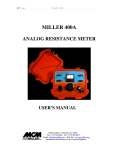
Page 1 of 14 MILLER 400A ANALOG RESISTANCE METER PART # 44500 USER’S MANUAL M. C. Miller Co., Inc. 11640 U.S. Highway 1, Sebastian, FL 32958 U.S.A. Telephone: 772 794 9448; Website: www.mcmiller.com Page 2 of 14 CONTENTS Page Description ………………………………………………………….. 3 Operating Instructions ……………………………………………… 4 Applications ………………………………………………………… 5 4-Electrode Applications ..…………………………………… Earth Resistivity Measurement ………………………... Electrolyte (Soil) Box Measurement …………………... 5 5 8 3-Electrode Application ……………………………………… 9 2-Electrode Application ……………………………………… 12 Maintenance & Calibration ………………………………………… 14 Page 3 of 14 DESCRIPTION When combined with appropriate electrodes (pins) and test leads, the MILLER-400A can be used to measure earth resistance or the resistance-toearth of a buried electrode, such as a ground rod or an anode, for example. Depending on the application, 4-Electrode, 3-Electrode or 2-Electrode, the MILLER-400A can be used to determine the following: The average earth resistivity to a specific depth (with the application of an appropriate multiplier to convert resistance to resistivity, based on the electrode separation distance) – 4-Electrode Application The resistivity of a soil sample, or of a liquid, via an electrolyte (soil/liquid) box (with the application of an appropriate multiplier to convert resistance to resistivity, depending on the box geometry) – 4-Electrode Application The resistance-to-earth of a buried electrode, such as a ground rod, or an anode, for example – 3-Electrode Application The resistance between two buried electrodes, such as two ground rods, or two anodes – 2-Electrode Application The current source in the MILLER-400A, which supplies current between the C1 and C2 terminals (with a load applied), is a 12V(rms) crystalcontrolled 97Hz square wave oscillator and the voltmeter inside the unit, which senses the potential difference (voltage drop) appearing across the P1 and P2 terminals, employs a very narrow band-pass filter centered at 97Hz What this means is that resistance measurements taken by the MILLER400A are unaffected by any stray interference signals (having frequencies other than 97Hz) that may be present in the earth during a measurement. The MILLER-400A has a resistance measurement range from 0.01Ohm (0.01Ω) to 1.1 MOhm (1.1MΩ) that is achieved by means of a set of 8 range settings and a system of internal “standard” resistors. External resistances (resistance values under test) are compared against the internal “standards, via a null balancing system, resulting in a determination of the external resistance values. The MILLER-400A runs on a set of replaceable C-size alkaline batteries, so there is no requirement to periodically re-charge the unit or to plug the unit Page 4 of 14 into a power source. Please see the “Maintenance” section for information on how to replace the batteries. OPERATING INSTRUCTIONS The test lead connections that are made to the “Current” terminals, C1 and C2, and the “Potential” terminals, P1 and P2, depend on the particular application of the MILLER-400A. The various connection requirements, as well as the various accessories required in each application are detailed in the “Applications” section. Regarding the applications that involve inserting electrodes (pins) into the earth, it is recommended that the electrodes (pins) be firmly driven into the earth (pins cannot be loose). Also, in dry soils, it is recommended that the soil around the pins be moistened in order that reliable (low resistance) contact is made to the surrounding soil. How to take a resistance reading: 1) Connect the test leads and set up the electrodes (pins) as outlined in the Applications section for your particular application. 2) When the approximate resistance (say of the local soil) is not known, move the range selector switch (labeled “Ohms Multiply By”) to the 100K setting and position the “Balance Dial” knob at “10”. 3) Pull the “Null Sensitivity” switch down to the “Low” position and note that the null indicating meter needle moves to the right, indicating too high a resistance setting. 4) While holding the “Null Sensitivity” switch in the “Low” position, step down through the resistance ranges (10K, 1K, 100Ω etc.) until the needle moves to the left of the null position (left of the center position) and then step back up one range. 5) Adjust the position of the “Balance Dial” until the needle is positioned at the null (center) location on the meter. 6) Multiply the “Balance Dial” setting by the range setting (setting on the switch labeled “Ohms Multiply By”) to obtain the resistance value. For example, for a “Balance Dial” setting of 4.5 and a range switch setting of 100Ω, the resistance value is 450Ω 7) Apply the resistance value to the calculation of resistivity using the appropriate formula for your application (see the Applications section below). Page 5 of 14 Note: You can increase the sensitivity of the resistance reading by holding the “Null Sensitivity” switch in the “High” position and fine tuning the balance, after finding the balance point in the “Low” sensitivity position. APPLICATIONS 4-ELECTRODE APPLICATIONS 1. Earth Resistivity Measurement This application uses 4 electrodes (pins). The electrodes are driven down into the earth the same distance and are evenly spaced in a straight line. A schematic of this arrangement is illustrated in Figure 1 below. Figure 1 Page 6 of 14 The MILLER-400A can be used in conjunction with M. C. Miller’s 4-lead (color-coded) test reel (catalog # 44700) and four heavy-duty (stainless steel) electrodes (soil pins) – catalog # 44720. The test leads are connected to the MILLER-400A as shown in Figure 1. With this arrangement, the MILLER-400A effectively measures the earth’s average resistance to a depth equal to the electrode spacing (S). Dr. Frank Wenner of the U.S. Bureau of Standards developed the theory behind this test in 1915 [1]. He showed that, if the electrode (pin) depth (d) is kept small relative to the separation between the electrodes (S), the earth’s average resistivity to a depth equal to the electrode spacing (S) can be obtained by applying the following formula: ρ =2πSR where R is the resistance value in ohms as determined using the MILLER400A, ρ is the resistivity in ohm.cm, π is the constant 3.1416, and S is the electrode separation in cm. Typically, the electrode (pin) spacing is not measured in centimeters but, rather, in feet (in the U.S.) or in meters (in most other countries). U.S. Example (electrode spacing measured in feet): Since there are 30.38 centimeters in 1 foot, the above formula can be written as: ρ (Ω.cm) = 2π x 30.38 x (electrode spacing in feet) x R (ohms) or, ρ (Ω.cm) = 191.5 x (electrode spacing in feet) x R (ohms) So, for example, if the MILLER-400A produces a resistance value of 15 ohms for an electrode (pin) spacing of 20 feet, the earth’s average resistivity value to a depth of 20 feet would be: ρ = 191.5 x 20 x 15 = 57,450 ohm.cm If the resistivity value is required to be expressed in ohm.m, rather than ohm.cm, the ohm.cm value is divided by 100. In the above example, the resistivity would be 574.5 ohm.m Page 7 of 14 Metric Example (electrode spacing measured in meters): Since there are 100 centimeters in 1 meter, the above formula can be written as: ρ (Ω.cm) = 2π x 100 x (electrode spacing in meters) x R (ohms) or, ρ (Ω.cm) = 628.32 x (electrode spacing in meters) x R (ohms) So, for example, if the MILLER-400A produces a resistance value of 15 ohms for an electrode (pin) spacing of 7 meters, the earth’s average resistivity value to a depth of 7 meters would be: ρ = 628.32 x 7 x 15 = 65,973.6 ohm.cm If the resistivity value is required to be expressed in ohm.m, rather than ohm.cm, the ohm.cm value is divided by 100. In the above example, the resistivity would be 659.73 ohm.m Note: The above formula is accurate only if the electrode depth (d) is small relative to the electrode spacing (S). An “S” value equal to, or greater than, 20 times the “d” value is recommended. This means that if d is 1 foot, for example, then S has to be at least 20 feet (or, if d is 0.3 meter, then S has to be at least 6 meters) The Wenner Method is the basis of an ASTM Standard Test Method (ASTM G57-78). 2. Soil Sample (or Liquid) Resistivity Measurement This application also uses 4 electrodes, however, in this case, the electrodes are an integral part of an electrolyte box, which is more commonly referred to as a soil box. For this application, the MILLER-400A can be used in conjunction with one of M. C. Miller’s soil boxes (catalog # 37008 or catalog # 37006) and 4 test leads (catalog # 37009). A schematic of the test arrangement is illustrated in Figure 2 below. Page 8 of 14 Figure 2 For this application, the test leads are connected to the MILLER-400A as shown in Figure 2. With this arrangement, the MILLER-400A determines the resistance of the soil sample, or of the liquid that fills the electrolyte box. In general, for a particular volume of soil sample (or liquid), as defined by the geometric constraints of the electrolyte box, the sample’s resistivity can be calculated from the resistance value determined using the MILLER-400A by applying the following formula: ρ = R A/L where ρ is the resistivity in ohm.cm, R is the resistance in ohms, A is the cross-sectional area of the current electrodes in cm squared, and L is the separation between the potential electrodes in cm. Page 9 of 14 Consequently, the ratio A/L represents a multiplication factor that needs to be applied to the resistance reading in order to obtain the sample’s resistivity value. Conveniently, for both M. C. Miller soil boxes, the A/L ratio is exactly 1cm. Consequently, when M. C. Miller soil boxes are used, the resistance reading in ohms determined using the MILLER-400A becomes the resistivity value in ohm.cm. If the resistivity value is required to be expressed in ohm.m, rather than ohm.cm, the ohm.cm value is divided by 100. For example a resistivity value of 2500 ohm.cm would be equivalent to 25 ohm.m 3-ELECTRODE APPLICATION The 3-Electrode Application can be used to measure the resistance-to-earth of a buried electrode, such as a buried ground rod or a buried anode. In this case, two of the electrodes are pins driven into the earth and the third electrode is the test electrode itself, for example, a ground rod or an anode. A resistance-to-earth measurement will actually comprise 3 components; the resistance of the electrode itself (the resistance of the ground rod or anode material, for example) including test leads, the electrode-earth contact resistance and the resistance of the surrounding earth. Typically, the resistance of the surrounding earth is the largest component of the resistance-to-earth measurement. The three electrodes are positioned in a straight line (ideally) as indicated in Figure 3 below. Page 10 of 14 Figure 3 As indicated in Figure 3, a jumper wire is connected between the C1 and P1 terminals on the MILLER-400A and test leads connect the “Potential Electrode” and the “Current Electrode” to terminals P2 and C2, respectively. Finally, a test lead connects the electrode under test (a ground rod or an anode, for example) to the C1 terminal. With this configuration, the MILLER-400A passes a current between the test electrode and the “Current Electrode” and generates a resistance reading based on the voltage dropped between the electrode under test and the “Potential Electrode”. The magnitude of the resistance reading will be a function of the separation (distance) between the electrode under test and the “Potential Electrode”, with respect to a fixed position for the “Current Electrode”. Page 11 of 14 A characteristic “resistance versus distance” plot is illustrated in Figure 4 below. Figure 4 This type of plot assumes that the “Current Electrode” (see Figure 3) is positioned far enough away from the electrode under test so that a “plateau” region is obtained in the plot. A 100 foot separation is typically recommended. However, it is suggested that a resistance versus distance curve be generated for any given situation in order to verify the existence of a plateau-type region which will allow an accurate determination of the electrode-to-earth resistance. Assuming that a plateau-type region is obtained, the resistance-to-earth value for the electrode under test will be the resistance value on the plot corresponding to the plateau region as illustrated in Figure 4. A general rule-of-thumb, which assumes that the “Current Electrode” is positioned sufficiently far away from the electrode under test, is that if the Page 12 of 14 “Potential Electrode” is positioned at a distance from the test electrode of 0.62 x D, where D is the distance between the electrode under test and the “Current Electrode”, the resistance reading observed will correspond to the resistance-to-earth value for the electrode under test. This particular configuration is illustrated in Figure 3. For example, if the distance between the electrode under test and the “Current Electrode” is 100 feet, the “Potential Electrode” should be positioned 62 feet from the electrode under test. However, again, it is suggested that resistance versus distance plots be generated in each instance. 2-ELECTRODE APPLICATION The 2-Electrode Application can be used to measure the resistance between two buried electrodes, such as two ground rods, or two anodes, for example. In this case, the two electrodes are the two buried components. Figure 5 below illustrates the measurement configuration. Page 13 of 14 Figure 5 As indicated in Figure 5, in this configuration, jumper wires are connected between terminals C1 and P1 and between terminals C2 and P2. In addition, test leads connect one of the electrodes to terminal C1 and the other electrode to terminal C2. Another configuration option, which is recommended for use when measuring small resistances, is to connect the potential terminals (P1 and P2) directly to the electrodes with separate test leads, thus eliminating the jumper wires. Such a configuration eliminates any voltage drop in the test leads due to current flow in the leads which would appear in series with the voltage drop occurring between the electrodes in the case of the configuration shown in Figure 5. The resistance reading determined by the MILLER-400A will be a direct measurement of resistance comprising 2 components; the resistance-to-earth contribution of each electrode (which itself comprises 3 components (see the Page 14 of 14 “3-Electrode Application” section above) and the earth’s resistance between the two electrodes. MAINTENANCE & CALIBRATION Other than changing the batteries, the MILLER-400A requires no maintenance. When the “Low Battery” indicator lights up (and remains ON) during a balancing procedure, the batteries should be replaced. The procedure to change the 8 C-size alkaline batteries in the unit is as follows: 1) Remove the 4 screws on the front panel and lift the panel out of the plastic case. 2) Turn the panel upside down and place on a clean (and dry) surface 3) Undo the four retaining clips and remove the two sets of 4 old batteries from their holder tubes. 4) Insert 4 new C-size alkaline batteries into each holder tube and reinstall the tubes making sure that the battery polarity is correct (as labeled) in each case. 5) Re-install the retaining clips. 6) Re-install the panel into its plastic case and re-install the 4 screws on the front side of the panel. With respect to calibration, it is recommended that the MILLER-400A be returned to M. C. Miller for re-calibration on an annual basis. Reference: [1] F. Wenner, “A Method of Measuring Earth Resistivity”, Bulletin of Bureau of Standards, Report # 258, Vol. 12, No. 3, Oct. 11, 1915 February 18, 2011


