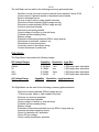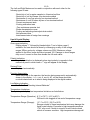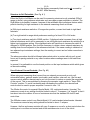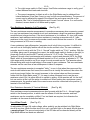
1
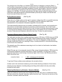
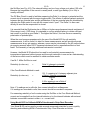
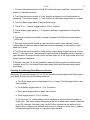
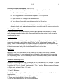
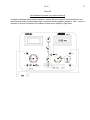
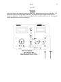
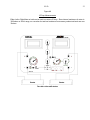
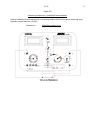
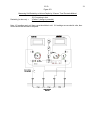
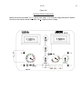
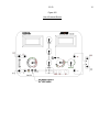
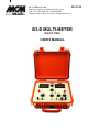
M. C. Miller Co., Inc.
MAN110
11640 U.S. Highway 1, Sebastian, Florida, U.S. A.
Tele: 1 (772) 794-9448; Fax: 1 (772) 589-9072
Website: www.mcmiller.com; email: [email protected]
B3-D MULTI-METER
(Part # 1106)
USER’S MANUAL
B3-D
2
MANUAL CONTENTS
Topic
Page
Left and Right Meters-Description & Uses
Liquid Crystal Digital Display
Structure-to-Soil Potentials
Use of Internal Current Controls
Use of Internal Batteries & Current Controls
Null Ammeter Current Measurements
Zero Resistance Ammeter
Bias Circuit
IR Drop Measurements
Resistance Measurements (Contact Checking)
Measuring Resistance by Voltmeter/Ammeter Method
Calibrating MCM’s Strip-Chart Recorder
Checking or Calibrating other Meters or Devices
Accuracy Check of Instruments
Checking Internal Batteries
Use of External Shunts
Maintenance of Panel and Case
3, 4, 5
5
6
6, 7
7, 8
8, 9
9
9, 10
10
10
10, 11, 12
12, 13
13
14
15
15
15
Figure #
1
2
3
4
5, 6
7
8
9
12, 13
14
15
B3-D
3
Left and Right Side Meters
The B3-D multi-meter is a digital version of the B3-A2 analog multi-meter. The left and right
side digital meters are of the liquid crystal type and are easy to read under outdoor lighting
conditions without the use of sunshades. The numeric displays are complete with automatic
decimal point, automatic polarity indication, automatic zeroing, automatic overrange indication,
automatic low battery indication and automatic function indicators (annunciators). The net
result of all these automatic features is greatly simplified operation with very little likelihood of
damage through accidental overload. Errors caused by misinterpretation of scales are almost
impossible.
Model B3-D has all of the functionality of the B3-A2 plus a 200V AC range and three direct
reading resistance ranges which take the place of the contact check circuit and permits easy
measurement of resistance of test leads, bonding resistors, etc.
When the B3-D is not in actual use, all pointed knobs should be pointing straight down. This
will conserve batteries and prevent accidental overload of metering circuits.
Left Meter (L Meter):
The Left Meter incorporates the following ranges:
D C Ammeter Ranges*
20mA
200mA
2A
20A
Capability
0-19.99mA
0-199.9mA
0-1.999A
0-19.99A
Resolution
.01mA
.1mA
1mA
10mA
*(all shunts have 20mV full scale IR drop)
DC Voltage Ranges
20mV
200mV
2V
20V
200V
Capability
0-19.99mV
0-199.9mV
0-1.999V
0-19.99V
0-199.9V
Resolution
.01mV
.1mV
1mV
10mV
.1V
Resistance Ranges
20ohms
2Kohms
2Mohms
Capability
0-19.99ohms
0-1.999Kohms
0-1.999Mohms
Resolution
.01ohm
1ohm
1Kohms
Input Res.
1000 ohms
10 mega-ohms
10 mega-ohms
10 mega-ohms
10 mega-ohms
B3-D
The Left Meter can be used for the following commonly performed tests:
-Rectifier or solar cell output current (external shunt required if above 2.0A)
-Output current of galvanic anode or impressed current anode
-Bond or drainage current
-IR drop on pipe, cable or other metallic structure
-Structure-to-earth potential (200mV range and up)
-Structure-to-water potential (200mV range and up)
-Anode-to-structure potential
-Structure-to-structure potential
-Output voltage of rectifier or solar cell array
-Potential across insulating fitting
-Battery voltage
-Electrode-to-electrode potentials (200mV range and up)
-Resistance of test leads, resistors, etc.
-Resistance of bond connections
-Continuity check of test station wiring
-Contact resistance of probe bars
Right Meter:
The Right Meter incorporates the following ranges:
DC Voltage Ranges
20mV
200mV
2V
20V
200V
AC Voltage Range
200V
Capability
0-19.99mV
0-199.9mV
0-1.999V
0-19.99V
0-199.9V
Capability
0-199.9V
Resolution
01mv
.1mv
1mv
10mv
.1V
Input Res.
1000 ohms
1-200 mega-ohms selectable
1-200 mega-ohms selectable
1-200 mega-ohms selectable
1-200 mega-ohms selectable
Resolution Input Impedance
.1V
450Kohms
The Right Meter can be used for the following commonly performed tests:
-Structure-to-earth potentials (200mV range and up)
- IR drop on pipe, cable or other metallic structure)
-Structure -to-structure potentials
-Anode-to-structure potentials
-Output voltage of rectifier or solar cell array
-Potential across insulating fitting
-Battery voltage
-Electrode-to-electrode potentials (use only 200mV range and up)
-Ammeter (requires accessory shunt)
-Check for hazardous AC potentials
-Check AC line voltage
-Check rectifier transformer operation
4
B3-D
The Left and Right Meters can be used in conjunction with each other for the
following types of tests:
5
-Resistivity of soil or water samples in 4-terminal soil box
-Resistivity of soil by Wenner four electrode method
-Resistance of very low value by four terminal method
-Resistance of over 2K ohms by two or four terminal method
-Current requirement tests
-Coating evaluation tests
- Zero resistance ammeter test
-Diode characteristic curves
-Testing and adjusting electrolysis drain switch
-Null ammeter tests
-Interference tests at foreign line crossings
Liquid Crystal Display:
Over-range Indication:
Display shows "1" followed by blanked digits. Turn to higher range if
available. No harm should be done by overranging on any of the voltage
ranges 200mv and up by voltages unless over 200V. Maximum voltage
applied to the 20mv range should not exceed 10V. Damage to shunt ranges
may occur if current is more than double the full scale value.
Polarity Indication:
No polarity indication is displayed unless input polarity is opposite to that
marked on panel in which case a "-" sign will appear in the display.
Decimal Point:
Displayed automatically.
Function Annunciator:
As an extra help to the operator, the function being measured is automatically
shown in the display - i. e. v, mv, A, ma, Ω, AC, so that there should be
no doubt whatsoever as to what is being displayed in the digital readout.
Low Battery Indication:
"Lo Bat" - See "Checking Internal Batteries"
Temperature Limitations:
The liquid crystal display has temperature limitations as listed below:
Temperature Range (Operation): 8° F to l76°F (-14°C to 80°C)
Will tend to be sluggish at low end of temperature range.
Temperature Range (Storage):
-37° F to l76°F (-35°C to 80°C)
Storage outside of these temperature limits may damage the
liquid crystal display. Exposure to high temperatures above
176°F may occur if meter is stored in truck of dark colored
vehicle in summer sunshine. High temperature damage will
B3-D
turn the display permanently black and is not covered by
the M.C. Miller warranty.
6
Structure-to-Soil Potentials: (See Fig. # 1)
Either the Right or Left Meter can be used for measuring structure-to-soil potentials (200mV
range or above) using reference electrodes such as copper-copper sulphate or calomel. The
Right Meter is preferable, however, because of the selectable input resistance feature which
permits checking for high resistance in the external measuring circuit as follows:
(a) With input resistance switch on 10 mega-ohm position, connect test leads to right hand
terminals.
(b) Turn right switch to range which produces a reading of at least 10% of full scale.
(c) Turn input resistance switch to 25MΩ position. If displayed value increases, there is high
external resistance and it will be necessary to use still higher input resistance by switching to a
higher input resistance setting. If the displayed value still continues to increase as switch is
changed to 200MΩ position, then it will be necessary to obtain a lower external resistance by
wetting down the soil adjacent to the reference electrode. If the same reading is obtained on
two adjacent input resistance settings, then the reading is correct and no further correction is
necessary.
The above procedure should be followed where electrode is in contact with dry soil, gravel,
frozen soil or paving material or any other locations where readings seem to be lower than
expected.
In general, it is preferable to use the lowest position on the input resistance switch which gives
an accurate reading.
Use of Internal Current Controls: (See Fig. #2)
When using and measuring direct current from an external source such as a dry cell,
automobile battery, galvanic anode, bond cable, small rectifier, solar cell, etc., the fine and
coarse controls and the rheostat can be cut into the circuit to reduce or control the magnitude
of the current. This is accomplished by throwing the ammeter toggle switch to "Amps With
Controls" position. To avoid overloading and overheating the controls, the rheostat and
controls must be used in proper sequence if current is over .3 A.
The 20ohm fine control is a special Ohmite Model J 50 -watt potentiometer / rheostat. The
maximum current at any setting should be limited to about 1. 5 amperes. It is "special" in that it
has about twice the number of turns of resistance wire that the standard 20 ohm 50 watt
control has.
The 500ohm coarse control is an Ohmite Model J 50 -watt standard potentiometer /rheostat.
The maximum current at any setting should be limited to about .3 ampere.
However, the fine and coarse controls will carry 5 amperes or more for a short period when the
rotating arm is on either end contact and all the resistance wire is out of the circuit.
B3-D
7
With the rheostat and the fine and coarse knobs in the counter clockwise position, the
resistance is at a minimum. NOTE that when measuring current from an external source the
current usually is slightly less when the amps toggle switch
is thrown to the left than it is when the toggle switch is thrown to the right. This is due to the
additional wiring and the resistance of the rheostat together with the slight resistance of the
end contacts of the fine and coarse controls.
Considering the maximum carrying capacity of the controls, it is obvious that if the current
exceeds 1.5 amperes, the rheostat must be used first to reduce the current to below 1.0
amperes, then use the fine control to further reduce the current value to the value desired or to
below. 3 ampere when it is safe to use the coarse control. It is safe to overload the se controls
by a factor of 2 for a few seconds (enough time to get a reading).
If the current is initially small (below 1.5 amperes), the fine control can be used. However,
when the current is between 4 amperes and 1. 5 ampere, the fine control may produce "jumpy"
control as the fine and coarse controls are wire-wound and each wire passed over by a
rotating arm results in a relatively large change in resistance. Therefore, use the rheostat for
smooth control is suggested. These factors will soon become apparent with use of the B-3D.
Use of Internal Batteries and Current Controls: (See Fig. #3)
The internal batteries may be used in series with an external source of direct current either to
increase or decrease the current. The internal batteries with controls can be connected in
series with a galvanic anode connected to a structure, to increase the output current of the
anode (as an example, to determine the amount of current needed to provide protection). Or
the internal batteries with controls can be connected in series, but bucking the external current
flow to reduce the magnitude of current and in some cases even to reverse the direction of
flow.
Also, internal batteries with controls can be used (without any external DC source) to supply
test current from a few milliamperes to about 2 amperes (or slightly more for a few seconds
testing). The magnitude of the current supplied from internal batteries can be adjusted with
internal controls, and can be switched on and off for testing by using the amps toggle switch or
the BAT toggle switch (depending on whether it is desired to completely open the current
circuit or merely disconnect the batteries leaving the current circuit closed through the shunt
and controls circuit). There are many uses for both types of testing.
When supplying test current from the internal batteries, it is essential that the sequence of use
of the RHEOSTAT, FINE Control and COARSE Control be carefully followed to avoid
overloading and overheating the controls. The following sequence is recommended:
(a) Be sure all knobs are in the normal vertical position.
(b) Connect test leads of circuit to be tested.
(c) Turn left range switch to ampere or milliampere range desired, depending on the value of
the current desired for testing.
(d) Throw AMPS toggle switch to AMPS WITH CONTROLS. Turn BAT toggle switch to 1.5 or
3 volts, depending on circuit resistance and value of current desired. If only a few milliamperes
B3-D
8
are desired; (1) turn FINE control slowly. If this does not provide sufficient current, return the
control to normal position and (2) turn COARSE control slowly and watch ammeter. Turn
control until most sufficient current is provided and then adjust the desired value with the FINE
control
If .3 ampere or more current is desired; (1) turn COARSE control slowly until almost the
desired value of current is obtained, then (2) turn F INE control to adjust to desired value. If
turning COARSE control to the maximum clockwise position does not provide sufficient
current, leave the COARSE control in the MAXIMUM position (where the slider is on the
maximum end contact) and then turn the FINE control. Note that if the current is above
approximately .5 ampere, the adjustment is "jumpy" because of the wire - wound control. Turn
the FINE control to provide slightly more current than is desired, and then (3) turn RHEOSTAT
clockwise which increases the resistance in the circuit and thus reduces the current. Again,
note that the RHEOSTAT is normally left in the counterclockwise position with minimum
resistance. Test current can be turned on and off with the AMPS toggle switch and the effects
of the test current can be measured on the right meter.
NOTE: When using the internal batteries and controls in series with an external DC source,
such as galvanic anode connected to a structure, it often will be found that when the AMPS
toggle switch is first thrown to AMPS WITH CONTROLS, the ammeter will show the galvanic
current flowing. When the battery is connected and the COARSE control is turned clockwise,
the current will first be reduced but when the COARSE control is turned further, the current will
increase up to the original value, then further increase when the potential of the battery being
applied by the position of the control exceeds the additional resistance put into the circuit. This
is somewhat difficult to understand, but a study of the method of connecting the controls and
the battery in the circuit will show the reason.
As soon as tests have been completed, turn off left and right meters, turn BATT and AMPS
toggle switches to OFF, return control knobs to normal position, THEN disconnect leads.
Null-Ammeter Method: (See Fig. #4)
The primary use of the Null-Ammeter circuit is for the measurement of direct current flowing on
structures such as metal-sheathed cables, pipelines and galvanic anode or impressed current
anode circuits. This method is especially valuable in locations where it is difficult or impossible
to open up a circuit to connect an ammeter in series and it eliminates having to calculate
current flow based on IR drop. The Null-Ammeter method of current measurement consists of
forcing (by means of batteries and controls) a measured amount of current through an
ammeter connected across a short section of the structure under test. The test current is
gradually increased until the IR drop on the section of structure becomes zero (null). This
indicates that the current flowing through the ammeter is exactly equal to the amount which
was formerly flowing along the structure. See "Wiring Diagram for Null-Ammeter Current
Measurements". Fig. #4 .
How To Measure DC Current by Null-Ammeter Method:
a. Make connections as shown in " Wiring Diagram for Null-Ammeter Current
Measurements", Fig. #4. Make sure that the ammeter and millivoltmeter test connection
points on the structure are kept from touching one another. Test leads should not be
less than # 16 AWG wire.
B3-D
9
b. Turn right range switch to 20mV range. Use 20ohm resistance range to verify good
contact between test leads and structure.
c. The current necessary to obtain a null on the Right Meter may be obtained from
internal batteries (if less than 2 amp) or may be from an external battery. The amount of
current may be adjusted by means of the internal fine and coarse controls on the
rheostat. See "Use of Internal Batteries and Current Controls" above. If no null can be
obtained, reverse leads to Left Meter and try again.
Zero-Resistance Ammeter (Left Terminals):
(See Fig. #5 )
The zero-resistance ammeter measurement is sometimes necessary when measuring current
in a very low resistance low potential circuit such as between a large low resistance galvanic
anode bed and a large structure. If the circuit resistance is, for instance, 0.1 ohm total (anode
resistance, lead resistance and structure resistance), inserting an ammeter with 0.1 ohm
resistance in the circuit to measure the anode current would reduce the current to 1/ 2 while
being measured; a 50% error in reading.
A zero-resistance type milliammeter / ammeter circuit is built into your meter. It is difficult to
use until one is thoroughly familiar with all the circuits and their uses. The zero-resistance
ammeter circuit is set up with the "R to L - Normal" toggle switch on "R to L" position. With the
Left Meter being used to measure the current, the amps toggle switch is thrown to the right (to
Amps with Controls) and the BATT switch is closed to 1.5 or 3 volts. The current is then
"pumped" through circuit and ammeter with batteries, controls and rheostat UNTIL the Right
Meter, which is connected across left-hand terminal on R to L position, is adjusted to "0". The
right range switch should be on 20 mv range for most accurate resuIts. The ammeter shunt,
internal wiring with controls and battery is then equal to zero resistance. This zero-resistance
ammeter can be used from a few milliamperes to about 2 amperes.
The zero-resistance ammeter is somewhat "tricky " to use, in that when the coarse and fine
controls with batteries are first turned, the current flow is usually first reduced, then when the
controls are turned further, the current increases to the original value and then increases
further Until the Right Meter reads "0". It is easy to show someone how to use the zeroresistance circuit, but it is rather difficult to explain in writing. A little practice will “do the trick",
but use caution at first until the action is understood. When making zero-resistance current
measurements, the positive lead of the current source must be connected to the positive (+)
terminal of the Left Meter.
Zero-Resistance Ammeter (4 Terminal Method):
(See Fig. #6)
Zero-resistance current measurements can also be made with the R to L – Normal toggle
switch in the Normal position, in which case the effects of both the ammeter and lead
resistances can be completely nullified. Four test leads are required, but otherwise the
procedure is the same as described above.
Use of Bias Circuit:
(See Fig. #7)
An adjustable DC bias (full scale voltage, either polarity) can be switched into Right Meter
circuit at any time. When the bias circuit is in use, a red pilot light on the panel should glow as
a warning signal. The amount and polarity of the DC bias can be observed directly on the
Right Meter before test leads are attached.
B3-D
10
The principal use of the Bias is to facilitate measurement of changes in potential (Delta V),
such as when measuring the change in a structure-to-soil potential during cathodic protection
current requirement tests; measuring resistance of anode, ground bed or structure to remote
earth or measuring soil resistivity by the 4-pin (Wenner) method, either in place to various
depths or in a Soil Box. For these resistivity tests the bias serves to offset the effects of both
polarization and residual galvanic potential between potential pins. Make sure that the bias
circuit is turned off when not in use.
IR Drop Measurements:
(See Fig. #8)
Either the Left or Right meter can be used to measure voltage drop (IR) on a metallic structure
such as a pipe, cable, steel piling, etc. The reading is used in conjunction with known
characteristics of the material to calculate magnitude of current flow.
Test leads should be kept as short as possible, preferably #16 or heavier, and connections to
the structure must be bright and shiny to insure low contact resistance. Use of the 20 ohm
resistance measuring circuit which is built into the Left meter is strongly recommended in order
to avoid erroneous readings caused by broken wires in test stations or poor contact with the
structure. External circuit resistance should be less than 10 ohms for good accuracy.
Resistance Measurements (Contact Check Circuit):
(See Fig. #9)
The Left meter has three direct reading resistance ranges; 0-20 ohms, 0-2000 ohms and 0-2M
ohms. Placing the Left range switch on either of these positions permits reading resistances
without making any adjustments or calculations. The circuit is designed to obtain accurate
enough results when there is an existing IR drop or similar potential of a few millivolts existing
in the circuit to be measured.
The principle use of the resistance measuring circuit is to check out test leads or test station
wiring for continuity.
When IR drops are to be measured using the 20mv range (internal resistance 1000 ohms) the
total external resistance should be kept below 10 ohms if possible. If a long piece of small
gauge test lead wire is used having a resistance higher than 2 ohms, the following correction
factor should be used:
correction factor
=
1, 000 + external circuit resistance
1,000
To get true IR drop multiply meter reading by the correction factor.
Another use for the resistance measuring circuit include checking resistance of bond wires,
checking for short between insulating flange and flange bolts (when bolts are presumably
insulated at both ends).
Measuring Resistance by Voltmeter / Ammeter Method:
(See Fig. # 10)
There are situations involving very low resistance (less than .001 ohm) or resistances above
2M ohms where the voltmeter / ammeter method must be used. There are two versions of the
voltmeter / ammeter method as follows:
B3-D
11
a. Two Terminal Method:
When the "R to L - Normal" toggle switch, which is located below the Right meter, is
thrown to the "R to L" position, the Right meter is connected to the left terminals of the
Multi- Combination Meter. This permits easy measurement of the resistance of any test
lead, resistor, bond wire or other device which is connected to the left hand terminals.
The necessary test current can be supplied from the internal 1. 5 or 3 volt batteries and
controlled to any value from less than one milliampere to about 2 amperes . The desired
value of test current is supplied and adjusted as outlined in the section "Amps With
Internal Controls and Batteries". It is desirable to use multiples of one such as 1mA,
10mA, .1amp, etc. to facilitate calculations in the field.
.
The disadvantage of this method is that it includes the resistance of the test
leads which may be large in comparison to the resistance of the unknown resistor
under test.
b.
Four Terminal Method:
When the "R to L - Normal" toggle switch is in the "Normal" position the Right meter
operates from the right hand terminals, which permits resistance measurement by the
four terminal method. This method is used where the effects of test lead and contact
resistance must be eliminated. Typical examples are as follows:
- Calibration of 4 lead test stations on pipe or cable
- Resistance-to-earth of structures such as grounding facilities
- Pipe-to-casing resistance
Except as noted above, test procedure is the same as for the two terminal method. Care
must be taken to make sure test clips from current and potential leads do not touch
each other.
voltmeter reading*
Regardless of which version is employed, resistance= ammeter reading*
*When voltmeter reading is in volts, ammeter reading must be in amperes. When
voltmeter reading is in millivolts, ammeter reading must be in milliamperes.
Electrode-to-Electrode Measurements (Soil Gradients): (See Fig. #11)
The voltage drop in the earth caused by cathodic protection currents, corrosion currents or DC
stray currents can be easily measured by using two matched copper sulphate electrodes
placed on the surface of the ground at desired spacing (usually between 5 ft. and 100 ft. ). The
preferred method is to use the Right meter as outlined above (making use of the variable input
resistance feature as necessary). Use only the ranges 200mv and above.
Soil Resistivity Measurements: (See Fig. #12 & 13)
Your Model B-3D can be used to measure soil resistivity over a very wide range of values over a much wider range than can be covered by any other soil resistivity measuring
instrument, by using external batteries or a dynamotor when needed. Connections are shown
in Fig. # 13 for use with the 4-pin method for measuring resistivity of soil in place to various
depths, or samples of soil or water in
B3-D
12
the Soil Box (see Fig. #12). The external battery can be of any voltage up to about 100 volts.
Because the magnitude of the current is usually small, a radio type battery (6v to 24v) is
usually sufficient.
The DC Bias Circuit is used to facilitate measuring the Delta V or change in potential and the
current circuit is opened with the amps toggle switch. The effects of residual galvanic potential
between the two potential pins and the polarization of the two potential pins are eliminated by
adjusting the Right meter to zero with the current circuit "open". The Delta V is then read
directly as soon as the amps switch is closed.
It is essential that the Right meter be on 200mv or higher range because internal resistance of
20mv range is only 1,000 ohms. It is desirable to use an external battery to obtain sufficient
test current to provide a good Delta V. The higher the Delta V, the less the error caused by
polarization of potential pins.
When the user becomes experienced in the use of the Model B-3D for soil resistivity
measurements, it will be found it is ideal for these measurements and will provide accurate
measurements at any pin spacing, whereas, errors may be introduced by the AC method when
pin spacing exceeds about 100 ft. because inductance and/ or capacitance effects of test
leads. The necessity of carrying additional instruments is avoided.
However, the Model B-3D should not be used for soil resistivity measurements by
inexperienced personnel without proper and thorough instruction in use and an understanding
of the factors which must be watched to obtain accurate results.
If an M. C. Miller Soil Box is used:
Resistivity (in ohm-cm)
=
Delta V (change in potential)
Current
If the Four-Electrode Method is used:
Resistivity (in ohm-cm)
=
=
191. 5 x spacing in ft. between adjacent pins
x Delta V (change in potential)
Current
Or
6.28 x spacing in cm x Delta V
Current
Note: If V readings are in millivolts, then current should be in milliamperes.
If V readings are recorded in volts, then current should be recorded in amperes.
For measuring resistivity of soil or water using the Soil Box or the Four-Electrode Method,
current can be supplied from the internal batteries or by the internal batteries with external
batteries connected in series in either + or - current lead.
Using Model B-3D to Calibrate MCM's Potentiometric Strip-Chart Recorder:
Your Model B-3D can be used to provide accurate measured potentials for use in quickly
checking and calibrating MCM's Potentiometric Strip- Chart Recorder as follows:
B3-D
13
1. Connect Left meter terminals of the B-3D to Recorder input terminals (- terminal of Left
meter to + Recorder terminal).
2. Turn Recorder function switch to "zero" position and adjust to mid scale position as
necessary. Turn function switch to "use" position and Recorder range switch to 1v range.
3. Turn Left Meter range switch to any ammeter range.
4. Throw "R to L - Normal" toggle switch to "R to L" position.
5. Throw battery toggle switch to 1. 5 V position and amps toggle switch to Amps with
Controls.
6. Turn large fine and coarse battery controls clockwise until Right meter reads exactly
-1.000 volts.
7. Recorder stylus should now be at right hand end of scale. Adjust calibrate control
(located behind right hand side of Recorder panel) as necessary to bring stylus to right
hand end of scale.
8. Turn Recorder function switch to Calib position. Adjust stylus to right hand end of scale
using "2. 5mV Adj Control" (located behind right hand side of Recorder panel). Recorder is
now calibrated. All ranges should now be accurate within 2% of full scale unless one of the
range resistors is defective.
9. Ranges other than 1V can be checked by adjusting battery controls to desired value
(between 0 and 3V ) and turning Right meter range switch and Recorder range switch
accordingly .
Checking or Calibrating Other Meters or Devices:
Almost any DC voltmeter range from 0 to 3V can be easily checked against the Right meter of
your Model B-3D by using the following technique:
a. Turn Right range switch to appropriate mV or V range; Turn left range switch to any
Amps position.
b. Throw battery toggle switch to 1.5 or 3V position.
c. Throw Amps toggle switch to Amps with Controls.
d. Throw toggle switch to "R to L" position.
e. Turn fine and / or coarse battery controls clockwise to produce desired reading on
Right meter. This same voltage will appear at the left terminals which can be connected
to any DC voltmeter, Recorder, relay, diode or other electrical device which is to be
tested. When using internal batteries as a source of voltage or current, the (-) negative
left hand terminal functions as a (+) positive output terminal.
B3-D
14
Accuracy Check of Instruments: (See Fig. # l4)
A comparison of the Left and Right meters can be easily accomplished as follows:
a. Throw left and right range switches to same range.
b. Throw toggle switch at bottom center of panel to "R to L" position.
c. Apply unknown DC voltage to left hand terminals.
d. Throw Amps - Amps with Controls toggle switch to left position.
e. Both meters should indicate within 1 % of each other ± one digit. If there is a greater
disparity check meter against known voltage to see which meter is reading erroneously.
Checking Internal Batteries:
All internal batteries should be frequently checked and replaced when necessary to avoid
costly damage caused by leaking cells. Remove all batteries when meter is to be stored for
more than a few days.
Amplifier Batteries:
Each meter uses one 9V battery, Eveready or equivalent. These are checked automatically
when meter is turned on and if below about 7V the "Lo Bat" indication will appear in the
display. When "Lo Bat" indication first appears there is only a few hours left before meter will
beg in to give erroneous readings. It is suggested that a spare be carried along when working
in remote rural areas. Battery life should exceed 150 hours of "on" time.
Bias Circuit:
Bias circuit uses one 3 volt lithium coil cell located on RH meter switch board, Eveready
#CR2032 is preferred. To check cell push bias or/off switch. If bias warning light glows, bias
cell is satisfactory. Note: It is not necessary to remove this battery for any reason other than
termination of Life.
Resistance Measuring Circuit:
Resistance measuring circuit uses one Alkaline AA cell, Eveready No. E-91 or equal. To check
this battery, place Left meter on 20 ohm or 2K ohm position, throw right meter range switch to
2v position and "R to L – Normal” toggle switch to “R to L” position. Battery voltage will appear
on Right meter; replace if below 1.30 volts.
1. 5 and 3V Batteries:
Three " D" cell, Eveready No. 950 or equivalent, are used with internal controls. To check
these batteries:
1. Turn left and right range switches to 20V range position.
2. Throw Amps toggle switch to Amps with Controls.
3 'Turn fine and coarse controls to full clockwise position.
B3-D
4. Throw "R to L - Normal" toggle switch to "R to L" position.
5. Throw Bat toggle switch to 1.5V position.
6. The sum of both meters should indicate at least 1. 4V.
7. Throw Bat toggle switch to 3V position.
8. The sum of both meters should indicate at least 2. 8V.
15
Battery Life:
Under average temperature and use, the batteries should last about six months. Storage or
use in high temperature environments tends to shorten battery life. Under low temperature use
conditions (below freezing) battery life will be somewhat less.
Use of External Shunts:
(See Fig. #15)
The use of an external shunt such as MCM's 100 Ampere Shunt permits either the Left or
Right meter to be used as an ammeter. The 100 Ampere Shunt has a resistance of .001 ohm,
which means that current flowing through the shunt will produce 1mv drop per ampere. This
millivolt drop can be measured by either the Left or Right meter. The 200mV range will make
either instrument serve as a 100 ampere ammeter. When using an external shunt with the Left
meter, the toggle switch below the left range switch must be in the "Amps, Volts, Ohms"
position.
The 100 Ampere Shunt can be mounted directly on the Left or Right hand terminals or can be
used several feet away from the Multi-Combination Meter by using suitable test leads
connected to the knurled potential terminals of the shunts.
Maintenance of Panel and Case:
Both the meter panel and the "Ruggedized Pelican" case are resistant to wear and tear
resulting from normal use. For appearances sake and to prevent possible surface leakage of
electrical currents, we recommend that the panel be kept clean and free of dirt by use of a
small folded cloth dampened with denatured alcohol or soap and water. Panel should be
allowed to dry thoroughly before use. Similar treatment of Orange Pelican case will keep it
clean and attractive.
B3-D
16
Figure #1
Structure-to-Soil Potentials
Do NOT use 20mV range for this range. Although Right Meter is preferred for this purpose (because of
variable input resistance), the Left Meter can also be used if the 10 mega-ohm internal resistance is
sufficient.
B3-D
Figure #2
Use of internal controls to control current from an external battery or other source of current.
17
B3-D
Figure #3
Use of Internal Batteries and Controls
18
B3-D
Figure #4
Null Ammeter Current Measurement
19
B3-D
Figure #5
Zero Resistance Ammeter (two terminal method)
20
B3-D
21
Figure #6
Zero Resistance Ammeter (four terminal method)
Completely eliminates effects of lead resistance. Used to find out how much current would flow if two
structures were solidly bonded together with a connection having negligible resistance. Note: It may be
necessary to reverse connections to Left Meter to obtain a zero reading on right meter.
B3-D
22
Figure #7
Bias Circuit
Use of bias to block out unwanted galvanic potentials such as between two soil pins or electrodes. The
adjust knob is turned until Right Meter reads zero. Any further change in reading can then be read
directly on Right Meter. Caution: Make sure that bias circuit is turned off when not in use. Warning light
should glow red when bias circuit is turned on.
B3-D
23
Figure #8
IR Drop Measurements
Either Left or Right Meter or both can be used to measure IR drop. Since internal resistance of meter is
1000ohms on 20mV range, no correction for test lead resistance is necessary unless test leads are over
10ohms.
B3-D
24
Figure #9
Resistance Measurements (also contact or continuity check)
If meter reads “1” followed by blank digits then the resistance exceeds the range; change to next higher
resistance range. This circuit is handy for checking continuity of test leads, test stations and resistance
of bond wires. Note: This circuit is designed to tolerate several mv of existing IR drop without causing
significant error in reading.
B3-D
Figure #10
Measuring Resistance by Voltmeter/Ammeter Method
Used for calibrating IR drop test stations or measuring resistors which are too low to measuring using
ohmmeter ranges (less than .01ohm).
Resistance =
Right Meter reading in mv
Left Meter reading in ma
25
B3-D
26
Figure #11
Electrode-to-Electrode Measurements (soil gradients)
Use Right Meter with range switch on any voltage range except the 20mv range. Use input resistance
switch as necessary to detect and/or eliminate effects of high contact resistance of electrodes.
B3-D
Figure #12
Measuring Resistivity of Sample Soil or Water in MCM “Soil Box”
Resistivity (in ohm-cm) =Delta V (change in potentials) x 1cm
Current
Use bias circuit to bring Right Meter to zero before closing ammeter switch. Note: If V reading is
recorded in mV, then current should be recorded in mA. If V reading is in volts then current reading
should be in amperes.
27
B3-D
Figure #13
Measuring Soil Resistivity to Various Depths by “Wenner” Four Electrode Method
Resistivity (in ohm-cm) =
191.5 x spacing in feet
X Delta V (change in potential)
Current
Note: If V readings are in mV then current should be in mA. If V readings are recorded in volts, then
current should be recorded in amperes.
28
B3-D
Figure #14
Accuracy Check of instruments
Meters should be read within 1% (+ 1 digit of each other). If an accurate voltage standard is used as
the source then meters should read within 1% (+ 1 digit) of source voltage.
29
B3-D
Figure #15
Use of External Shunts
30
B3-D
31