1
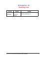
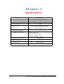
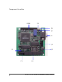
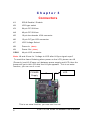
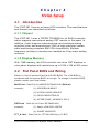
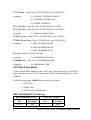
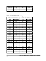
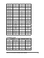
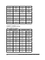
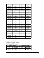
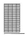
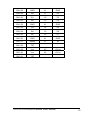
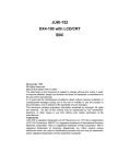
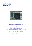
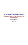
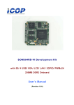
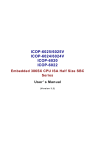
ICOP-2811 PC/104 VGA/LCD Module User’s Manual (Version 1.0) Copyright Notice This document is copyrighted, 2002 by ICOP Technology Inc. All rights are reserved. The information in the manual is subject to change without notice in order to improving products. No part of this manual may be reproduced, copied, translated or transmitted in any form or by any means without the prior written permission of the manufacturer. ICOP Technology Inc. assumes no responsibility for any inaccuracies that may be contained in this document. ICOP Technology Inc. makes no commitment to update or to keep current the information contained in this manual. Copyright 2002 by ICOP Technology Inc. All rights reserved. Ver.1.0 2002, Printed in Taiwan Trademarks Acknowledgments All brand names and trademarks are the properties and registered brands of their respective owners. ii Table of Contents Table of Contents Chapter 0 Packing List........................................... 1 Chapter 1 Specifications........................................ 2 Chapter 2 Jumper Setting ...................................... 5 Chapter 3 Connectors ............................................ 6 Chapter 4 SVGA Setup ........................................... 7 Warranty ............................................................................16 iii Chapter 0 Packing List Function ICOP-2811 Function VGA/LCD Module Package ICOP-2811 PC/104 VGA Module Utility and Drivers x 1 ICOP PC/104 VGA/LCD Module User's Manual 1 Chapter 1 Specifications Features Chipset Bus Interface Video Memory Resolution ICOP-2811 TOPRO (HMC) TP6508IQ PC/104 standard compliant 1MB Up to 1024X768 @ 256 colors or 1280X1024 @ 16 colors 1 VGA BIOS Socket Display Connector 15-Pin D-type VGA, 10-Pin box-header VGA 44-pin box-header LCD) Power Requirement Board Weight Board Size Storage Temperature 2 +5V @ 200mA 75 g 96mm X 90 mm 0 ~ +60°C ICOP PC/104 VGA/LCD Module User's Manual Description The TP6508IQ is an advanced single-chip flat panel VGA controller. It’s used for small-size computer or notebook computer system with simple operation and powerful features. Also it contains all of the functions and supports logic required to implement the IBM VGA display standards and enhanced display modes on LCD, PLASMA, EL panel and TV display at register and BIOS level compatiable. A simultaneous display technology is implemented in TP6508IQ to be used for CRT/Flat panel, LCD/TV display. For minimum chip-count or board-space, it can design to complete a video subsystem with only one 256kx16 DRAM (512k Bytes). This video subsystem can support all panel type without any glue logic or external frame buffer. Display memory With 1 MB memory, the VGA controller can drive CRT displays with resolutions up to 1024 x 768 at 256 colors (or 1280 X 1024 at 16 colors). Resolution 1280x1024 @ 16 colors 1024x768 @ 256 colors 800x600 @ 64K colors 640x480 @ 16.7M colors Software Support/Application Drivers: Windows 3.1/ 95/ 98/ NT Interface PC/104 standard compliant Connector: 15-pin D-Type VGA external connector 10-pin box header VGA connector 44-pin box header for LCD connector ICOP PC/104 VGA/LCD Module User's Manual 3 Component Location CON1 J9 J8 J7 J6 J5 J1 J2 J3 4 J4 ICOP PC/104 VGA/LCD Module User's Manual Chapter 2 Jumper Setting IRQ 9 Select (J1) Close: ENABLE Open: DISABLE LCD Type Select (J2) Type of Display 1-2 3-4 5-6 7-8 Address of VGA BIOS 1 Standard CRT C C C C 00000~07FFF Hex 2 Mono DSTN 640x480 C C C O 08000~0FFFF Hex 3 Color DSTN 640x480 C C O C 10000~17FFF Hex 4 16-bit TFT 640x480 C C O O 18000~1FFFF Hex 5 18/24-bit TFT 640x480 C O C C 20000~27FFF Hex 6 16-bit TFT 800x600 C O C O 28000~2FFFF Hex 7 18/24-bit TFT 800x600 C O O C 30000~37FFF Hex 8 EL 640x480 C O O O 38000~3FFFF Hex * Note: “C” means “close”; “O” means “open” LCD Voltage Select (J7) 1-2: 5V 2-3: 3.3V ICOP PC/104 VGA/LCD Module User's Manual 5 Chapter 3 Connectors J1 IRQ 9 Enable / Disable J2 LCD type select J3 64-pin PC/104 bus J4 40-pin PC/104 bus J5 10-pin box-header VGA connector J6 15-pin D-Type VGA connector J7 LCD Voltage Select J8 Power In (Note) J9 Power Out (Note) CON1 44-pin LCD connector Note: J8 and J9 are for “Voltage to LCD after H-Sync signal ouput” To avoid the frame flickering when power on the LCD, please use J8 (Power In) and J9 (Power out) between power supply and LCD, then the power will get in the LCD after the H-Sync appears. This is an extra function, you can use it or not. POWER Supply J8 J9 LCD This is an extra function, you can use it or not. 6 ICOP PC/104 VGA/LCD Module User's Manual Chapter 4 SVGA Setup 4.1 Introduction The ICOP-2811 has an on-board VGA interface. The specifications and features are described as follows: 4.1.1 Chipset The ICOP-2811 uses a TOPRO TP6508IQ for its SVGA controller, which supports conventional analog CRT monitor or flat panel. In addition, it also supports interlaced and non-interlaced analog monitors (color and monochrome VGA) in high-resolution modes while maintaining complete IBM VGA compatibility. Multiple frequency (multisync) monitors are handled as if they were analog monitors. 4.1.2 Display Memory With 1 MB memory, the VGA controller can drive CRT displays or color panel displays with resolutions up to 1024 x 768 at 256 colors. 4.2 Flat Panel BIOS and Wiring Below is a list of optional Flat Panel SVGA BIOS. The VGA BIOS is combined with the system BIOS in a single. To change to another BIOS please contact your local dealer. MLCD.dat - Data File for MONO DSTN640*480 (Default) example : (1) HOSIDEN HLM6667 (2) HITACHI LMG5160XUFC (3) CASIO MD650TS00-01 (4) OPTREX DMF_50260NFU-FW-8 DSTN.dat - Data file for Color DSTN640*480 example : (1) Sanyo LCM-5331-22NTK (2) SHARP LM64C35P TFT_S1.dat - Data File for TFT640*480-Sync (16 BIT) ICOP PC/104 VGA/LCD Module User's Manual 7 TFT_S2.dat - Data File for TFT640*480-Sync (18/24 BIT) example : (1) HITACHI TX26D60/TX24D55 (2) TOSHIBA LTM09C015A (3) SHARP LQ10D321 TFT_LP1.dat - Data File For TFT640*480-LP (16 BIT) TFT_LP2.dat - Data File For TFT640*480-LP (18/24 BIT) example : (1) Toshiba LTM09c015A) TFT86_S1.dat - Data File for TFT800*600_sync (16 BIT) TFT86_S2.dat Data File for TFT800*600_sync (18/24 BIT) example : (1) NEC NL8060AC26-05 (2) NEC NL8060AC26-04 (3) NEC NL8060BC31-02 EL.dat - Data File for EL640*480 example : (1) PLANAR EL640.480-A PLASMA.dat - Data File for PLASMA640*480 example : (1) PANASONIC S817 CRT/Flat Panel Mode All the above BIOS support either CRT only, Flat Panel only or CRT/Flat Panel simultaneously. To set the mode a Panel Switching Utility is used. USAGE: At DOS prompt type >SW508 then Screen will show 1. CRT Only 2. Panel Only 3. CRT/Panel Simutaneous NEC NL6448AC33-18 wiring NEC NL6448AC33-18 8 ICOP-2811 CON1 Pin Pin Name Pin Pin Name CN1-1 GND 3 GND ICOP PC/104 VGA/LCD Module User's Manual CN1-2 CLK 35 SHFCLK CN1-3 Hsync 38 LP CN1-4 Vsync 36 FLM CN1-5 GND 4 - CN1-6 R0 27 P18 CN1-7 R1 28 P19 CN1-8 R2 29 P20 CN1-9 R3 30 P21 CN1-10 R4 31 P22 CN1-11 R5 32 P23 CN1-12 GND 33 - CN1-13 G0 19 P10 CN1-14 G1 20 P11 CN1-15 G2 21 P12 CN1-16 G3 22 P13 CN1-17 G4 23 P14 CN1-18 G5 24 P15 CN1-19 GND 34 - CN1-20 B0 11 P2 CN1-21 B1 12 P3 CN1-22 B2 13 P4 CN1-23 B3 14 P5 CN1-24 B4 15 P6 CN1-25 B5 16 P7 CN1-26 GND 39 - CN1-27 ENAB 37 MDE CN1-28 Vcc 43 Vcc ICOP PC/104 VGA/LCD Module User's Manual 9 CN1-29 Vcc 44 Vcc CN1-30 NC - - CN1-31 NC - - NEC NL6448AC30-10 wiring NEC NL6448AC30-10 10 ICOP-2811 CON1 Pin Pin Name Pin Pin Name CN1-1 CLK 42 SHFCLK CN1-2 Hsync 38 LP CN1-3 Vsync 36 FLM CN1-4 DE 37 MDE CN1-5 - - P0 CN1-6 B0 10 P1 CN1-7 B1 11 P2 CN1-8 B2 12 P3 CN1-9 B3 13 P4 CN1-10 - 14 P5 CN1-11 - 15 P6 CN1-12 G0 16 P7 CN1-13 G1 17 P8 CN1-14 G2 18 P9 CN1-15 G3 19 P10 CN1-16 - 20 P11 CN1-17 R0 21 P12 CN1-18 R1 22 P13 ICOP PC/104 VGA/LCD Module User's Manual CN1-19 R2 23 P14 CN1-20 R3 24 P15 CN1-21 - - P16 CN1-22 - - P17 CN1-23 - 27 P18 CN1-24 - 28 P19 CN1-25 - 29 P20 CN1-26 - 30 P21 CN1-27 - 31 P22 CN1-28 - 32 P23 CN1-29 PVcc 5 LCD Vdd CN1-30 Vcc 43 Vcc CN1-31 MODE 44 Vcc CN1-32 GND 3 GND CN1-33 GND 4 GND CN1-34 Vdd +12 1 +12 CN1-35 ENABKL 40 ENABKL CN1-36 GND 39 GND LJ32H028 wiring LJ32H028 ICOP-2811 CON1 Pin Pin Name Pin Pin Name CN1-1 D1 11 P2 CN1-2 D0 12 P3 CN1-3 D3 9 P0 CN1-4 D2 10 P1 CN1-5 CP2 35 SHF_CLK ICOP PC/104 VGA/LCD Module User's Manual 11 CN1-6 GND 3,4 GND CN1-7 CP1 38 LP CN1-8 GND 33,34 GND CN1-9 S 36 FLM CN1-10 - - - CN1-11 - - - CN1-12 - - - CN1-13 +5V 43,44 +5V(Vdd) CN1-14 - - - CN1-15 +12V 1,2 +12V SHARP LQ10D42 wiring (640 X 480 TFT Color) 12 SHARP LQ10D42 ICOP-2811 CON1 Pin Pin Name Pin Pin Name CN1-1 GND 3,4 GND CN1-2 CLK 42 SHFCLK CN1-3 Hsync 38 LP CN1-4 Vsync 36 FLM CN1-5 GND 3,4 GND CN1-6 R0 21 P12 CN1-7 R1 22 P13 CN1-8 R2 23 P14 CN1-9 R3 24 P15 CN1-10 R4 25 P16 CN1-11 R5 26 P17 ICOP PC/104 VGA/LCD Module User's Manual CN1-12 GND 3,4 GND CN1-13 G0 15 P6 CN1-14 G1 16 P7 CN1-15 G2 17 P8 CN1-16 G3 18 P9 CN1-17 G4 19 P10 CN1-18 G5 20 P11 CN1-19 GND 3,4 GND CN1-20 B0 9 P0 CN1-21 B1 10 P1 CN1-22 B2 11 P2 CN1-23 B3 12 P3 CN1-24 B4 13 P4 CN1-25 B5 14 P5 CN1-26 GND 3,4 GND CN1-27 ENAB 40 M CN1-28 Vcc 43,44 Vcc +5V CN1-29 Vcc 43,44 Vcc +5V CN1-30 R/L - - CN1-31 U/D - - SHARP LQ12S31 wiring (800 X 600 TFT Color) SHARP LQ12S31 ICOP-6052V CON1 Pin Pin Name Pin Pin Name CN1-1 GND 3 GND ICOP PC/104 VGA/LCD Module User's Manual 13 14 CN1-2 CLK 35 SHFCLK CN1-3 GND 4 GND CN1-4 Hsync 38 LP CN1-5 Vsync 36 FLM CN1-6 GND 8 GND CN1-7 GND 8 GND CN1-8 GND 8 GND CN1-9 R0 27 P18 CN1-10 R1 28 P19 CN1-11 R2 29 P20 CN1-12 GND 8 GND CN1-13 R3 30 P21 CN1-14 R4 31 P22 CN1-15 R5 32 P23 CN1-16 GND 39 GND CN1-17 GND 39 GND CN1-18 GND 39 GND CN1-19 G0 19 P10 CN1-20 G1 20 P11 CN1-21 G2 21 P12 CN1-22 GND 39 CN1-23 G3 22 P13 CN1-24 G4 23 P14 CN1-25 G5 24 P15 CN1-26 GND 41 GND CN1-27 GND 41 GND ICOP PC/104 VGA/LCD Module User's Manual CN1-28 GND 41 GND CN1-29 B0 11 P2 CN1-30 B1 12 P3 CN1-31 B2 13 P4 CN1-32 GND 41 GND CN1-33 B3 14 P5 CN1-34 B4 15 P6 CN1-35 B5 16 P7 CN1-36 GND 41 GND CN1-37 ENAR 37 M CN1-38 TST - - CN1-39 Vcc 43 +5Vcc CN1-40 Vcc 44 +5Vcc CN1-41 TST - - ICOP PC/104 VGA/LCD Module User's Manual 15 Warranty This product is warranted to be in good working order for a period of one year from the date of purchase. Should this product fail to be in good working order at any time during this period, we will, at our option, replace or repair it at no additional charge except as set forth in the following terms. This warranty does not apply to products damaged by misuse, modifications, accident or disaster. Vendor assumes no liability for any damages, lost profits, lost savings or any other incidental or consequential damage resulting from the use, misuse of, or inability to use this product. Vendor will not be liable for any claim made by any other related party. Return authorization must be obtained from the vendor before returned merchandise will be accepted. Authorization can be obtained by calling or faxing the vendor and requesting a Return Merchandise Authorization (RMA) number. Returned goods should always be accompanied by a clear problem description. 16 ICOP PC/104 VGA/LCD Module User's Manual