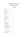
1
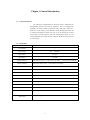
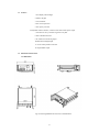
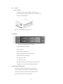
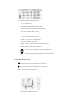
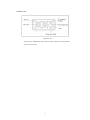
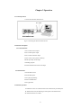
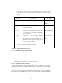
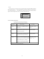
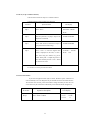
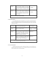
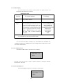
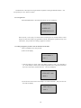
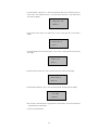
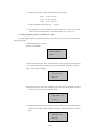
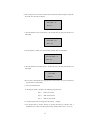
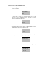
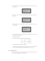
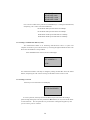
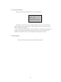
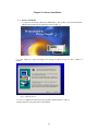
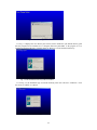
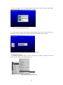
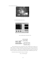
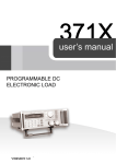
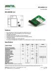
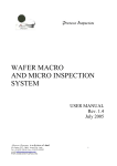
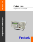
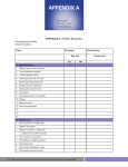
Programmable DC Electronic Load
L300 user manual
CONTENTS
CAUTION...................................……...........................2
SAFETY NOTES......................….................................2
Chapter 1 General Introduction……...........................3
1.1 General Introduction............……..........................3
1.2 Specification...............................….......................3
1.3 Features...........................................…..................3
1.4 Dimension and Structure......................….............3
1.4.1 Dimensions...........................................…..........3
1.4.2 Structure....................................…..........….....5
1.4.2.1 Front view.................................................….5
1.4.2.2 Rear view..................................................….…7
Chapter 2 Operation...........................................……8
2.1 General Operation...................................................8
2.2 Function Introduction.............................................8
2.2.1. Main functions....................................................8
2.2.2 Sub-functions.......................................................8
2.3 The Operation of the Functions.............................8
2.3.1 I-set......................................................................9
2.3.2 P-set....................................................................10
2.3.3 R-set....................................................................11
2.3.4 Store Data Function............................................11
2.3.5 Recall Data Function..........................................12
2.3.6 OUT ON/OFF key………….….............….......12
2.3.7 The Menu. Operation…….................................13
2.3.7.1 Set Max Current………..................................13
2.3.7.2 Set Max Power…………................................13
2.3.7.3 Program Set.....................................................11
2.3.7.4 Set up the Communication............................19
2.3.7.5 Set up Communication Address (0~254)...….20
2.3.7.6 Setting a Pass word…… ............................…20
2.3.7.7 Set up SAVE OPTION...............................…21
2.3.7.8 EXIT Function..........................................…..21
Electronic Load Software
Chapter 3 Software Installation...............................22
3.1 Installation................................................…..........22
3.2 Starting the program......….....................................24
3.3 Uninstalling the program.......................................26
CAUTION
Before switching on the DC Electronic load, the protective earth terminal
of this instrument must be connected to the protective conductor of the AC line
power cord. The AC line plug shall be inserted only in a socket outlet provided
with a negated by the use of an extension cord (or power cable) without a
protective grounding conductor.
SAFETY NOTES
The following general safety precautions must be observed during all
phases of operation, service, and repair of this instrument. Failure to comply with
these precautions or with specific warnings elsewhere in this manual violates
safety standards of design, manufacture, and intended use of the instrument. The
Manufacturer assumes no liability for the customer’s failure to comply with these
requirements.
Grounding the Instrument
This product is provided with a protective ground terminal. To minimize
shock hazard, the instrument chassis and cabinet mush be connected to an
electrical ground. The instrument must be connected to the AC Electronic Load
mains through a three-conductor power cable, with the third wire firmly
connected to an electrical ground (safety ground) at the power outlet. For
instruments designed to be hard-wired to the AC power lines, connect the
protective ground terminal to a protective conductor before any other connection
is made. Any interruption of the ground conductor or disconnection of the
protective ground terminal will cause a potential shock hazard that could result in
personal injury. If the instrument is to be energized via an external
autotransformer for voltage reduction, be certain that the autotransformer
common terminal is connected to the neutral of the AC power lines..
Keep Away From Live Circuits
Operating personnel must not remove instrument covers. Component
replacement and internal adjustments must be made by a qualified service
personnel. Do not touch components with power cable connected. Under certain
conditions, dangerous voltages may exist even with the power cable removed. To
avoid injuries, always disconnect power, discharge circuits and remove external
voltage sources before touching components. Do not substitute parts or modify
the Instrument in any way that may introduce additional hazards. Do not install
substitute parts or perform any unauthorized modification to the instrument.
Return the instrument to a qualified dealer for service and repair to ensure that
safety features are maintained.
2
Chapter 1 General Introduction
1.1
General Introduction
The L300 Series Programmable DC Electronic Load is small-sized DC
programmable electronic load. with nice appearance. Also it is equipped with
backlight LCD display, Numeric keypad and rotary code switch, which let it
much easier to use. Voltage, current and power can all be displayed on the LCD
or computer and tableau is distinct and clear. It can be operated at con stant
current mode, constant resistance mode and constant power mode. It is an
essential instrument for scientific research, education, laboratory, test, service and
so on institutions.
1.2
Specifications
Model
L 300
No. of Inputs
1
Input voltage
DC
0 to 360V
Input current
0 to 30A
Input power
0 to 300W
Voltage resolution
0.000-3.999±(0.2%+3mV); 4.00-35.999±(0.2%+30mV); 36.0-360.0V±(0.3%+300mV)
Current resolution
0.000-2.999±(0.2%+3mA); 3.00-30.00±(0.2%+30mA)
Lowest Conductive Resistance
≤ 0.08Ω
Ripple
≤ 10mVpp
Communication
RS232
Monitor software
Includes VC++ / VB / DELPHI / LABVIEW / COM Modules
Memory
Protective mode
Power voltage
Weight
Accessories
Option Parts
10 location EEPROM
Over voltage, over current, over power, over heating and polarity-reversing
AC 110/220 @ 60/50HZ
11 lbs
Software, users manual, AC power cable, handlebars, RS232 cables
Rack mounting hardware
3
1.3
Features
1. LCD display with backlight.
2. Numeric keypad.
3. 1mV resolution
4. Over current protection
5. Over power protection
6. Adjustable constant resistance, constant current and constant power output.
7. All values are set by a numeric keypad or rotary dial.
8. Power shutdown function
9. PC software for monitoring output
10 Small sized and lightweight.
11. Can be used in parallel connection.
12. Programmable output.
1.4
Dimensions and Structure
1.4.1 Dimensions
Fig 1 EL 300 Programmable DC Electronic Load Dimensions
4
1.4.2
Structure
1.4.2.1
Front view
Front panel consists of the LCD display, numeric keypad
and the rotary dial for entering current, power or resistance values.
Please see the diagrams below.
Fig2. Front view of L300 DC electronic load
1. LCD display
Fig3. EL 300 electronic load LCD Display
The upper half of the LCD display:
The current value,
Voltage value and output status
(ON/OFF represent power source output status)
The lower half of the LCD display:
The output power value.
The current preset value
Operating mode: (IS, PS, RS, SW represents constant current,
constant power, constant resistance and program output).
2. Arrangement of the Keyboard
When in the input state, the keyboards enters the numeric
value that is printed on the Keypads. When in the command
Mode (Store, Recall, etc) the Keypad when pressed will enter
the function written in blue above the Keypad.
5
Fig4. L300 Electronic load Keyboard layout
0~9: The Numeric keys
Out ON/OFF: Switches the output ON or OFF
Store: Saves the present operating values in memory
R-set: Sets a constant resistance value
START: Starts a previously entered program
I-set: Sets the constant current value
STOP: Stops a previously entered program
P-set Sets a constant power value
Recall: Recalls a previously stored set of operating values.
Menu: Displays the Menu items on the LCD
: The up arrow key scrolls through the menu items upward
: The down arrow key scrolls through the menu items downward
3. Rotary dial and function keys
: The left arrow key moves the display cursor to the left
: The right arrow key moves the display cursor to the right
ESC: exits a menu item or setup screen
OK: Enters a menu value or selects a menu item
Fig5. Rotary dial and function keys
6
1.4.2.2 Rear view
Fig6. Back view
The fuse can be changed easily using a small screwdriver. Please use a fuse within the
range of 0.3-0.5A./250V
7
Chapter 2 Operation
2.1 General operation
1. Connect the electronic load to the PC
Fig 2.1 Connecting the electronic load to the PC
2.2 Function descriptions
2.2.1. Main functions
1. Set a constant current output
2. Set a constant power output
4. Set a constant resistance output
5. Store 10 sets of setup values in memory
6. Recall previously stored setups
7. Start/Stop program
8. Switch ON/OFF the electronic load output
2.2.2 Sub-functions
1. Set maximum current
2. Set maximum power
3. Set up the programming
4. Set PC communication
5. Set up password
2.3 Function operation:
As stated above there are 8 main functions and 5 sub-functions provided by the
EL 300 electronic load, the following is a description of the functions and
sub-functions and how to us them..
8
2.3.1 I-set (setting a constant current value )
Setting a constant DC current output is the first main function of the L300 programmable
DC electronic load, The two methods to set a constant DC current input value is using the
Numeric keyboard or the rotary button. Please see the following chart for the operation
procedure.
Procedure
Step 1
Operation details
Press “ I-set ”
LCD display
SET CURR=0.00A
NEW=
Step 2
Enter the password (Or jump to step 4 if there is
no keyboard pass word)
ENTER PASS WORD
Step 3
Press the “ OK ” button (the LCD will return to step
2 if you entered the wrong password. Reenter the
correct Password
ENTER PASS WORD
Step 4
Press “ I-set ” to enter the original current value
displayed on the LCD, or enter a new value by using
the numeric key pad or rotate the “ Rotary SW ” to
adjust the current to a new value and then press the
“ I-set ” to enter the new value
SET CURR = 2.00A
NEW=
To exit the I set setup screen press the ESC button
Example:
Setting the input current to 3.12A
1. To set a constant current using Numeric keyboard
Step1. Press “ I-set ” key,
Step2. Enter the password using the Numeric keyboard (if the keyboard is unlocked, go to step 4)
Step3. Press “ OK ” button (if the password is wrong, go to step2 and enter the correct password)
Step4. Press “ 3 ”, “ . ”, “ 1 ” and “ 2 ” keys to enter the new voltage value,
Step5. Press the “ I-set ” button to enter the new current value.
2. To set a constant current using the Rotary dial
Step1 If the keyboard has no password, rotate the “ Rotary Dial", and the current will continuously
changed from its previous value according the direction rotation. (Clockwise increases, counter clockwise
decreases).
When I-Set set button is pressed the, cursor will initially be displayed under the least significant digit as
shown on the LCD, Pressing the ◄ button moves the cursor to the digit to the left. Pressing the. ► Button
moves the cursor to the next digit to the right.
9
Example:
To set the current to 3.12A: move the cursor to the left most digit by pressing the ◄ button. Rotate the
Rotary dial until the digit is a 3. Then press the ► button the select the next digit on the right. Rotate the
rotary dial until the digit is a 1. Press the ► button a third time and then rotate the rotary dial until the
digit is a 2. Please see figures below. Press “ I-set ” button to enter the new value.
0.000A 0.000V OF
0.0W 3.12A IS
2.3.2 P-set (setting a constant power)
EL 300 electronic load can be set a constant power .
The Constant power setup procedure is as following:
Procedure
Operation details
LCD display
Step 1
Press “ P-set ” to display the initial
power setting
SET POWER = 30.0W
NEW=
Step 2
Enter the password ( Or jump to step 4 if the
ENTER PASWORD
keyboard has no password)
Step 3
Press “ OK ” button ( it will return to step 2
ENTER PASWORD
if your password is wrong for reentering)
Step 4
Press “ P-set ” to enter the original value which SET POWER = 30.0W
displayed on the LCD, or enter a new value by
using the numeric keypad or rotate the
“ Rotary dial ” to the new power value and
then press P-SET to enter the new value
To exit the P- set screen press the ESC button
10
NEW=
72.2
2.3.3 R-set (set up a constant resistance)
L300 electronic load can be setup for a constant resistance.
Constant resistance setup procedure is as following:
Procedure
Step 1
Operation details
Press “ R-set ”
LCD display
SET RISIS = 200.0Ω
NEW=
Step 2
Enter the password ( Or jump to step 4 if the
ENTER PASWORD
Keyboard is unlocked)
Step 3
Press “ OK ” button ( it will return to step 2 if
ENTER PASWORD
your password is entered wrong)
Step 4
Press “ R-set ” to enter the original value
ET RISIS = 200.0 Ω
which is displayed on the LCD, or enter a
NEW=
50.0
new value using the numeric key pad or
rotate “ Rotary SW ” to adjust the power to a
new value and then press the “ R-set ” button
to enter the new value
To exit the P- set screen press the ESC button
2.3.4 Store data function
If you have and application that requires Current, Resistance power values that are
used continuously or are not changed. It may be desirable to use the Store Data Function.
This function stores Current, power and resistance settings in memory for later use. Ten
sets of values may be stored in the L300 memory with a location number assigned to it .
Procedure.
Step 1
Operation description
Press “ Store ” button
11
LCD display
****V
****A
****W
**
Step 2
Enter the memory number you want to
store the values in (from 1 to 10) using
the numeric keypad or rotating the rotary
dial
Step 3
Press the “ OK ” button to confirm the
values, if the number is out of the range of
1 to 10, the display will return to Step 2
for reentering
STORE 1
STORE *
To exit the store menu press the ESC button
2.3.5 Recall data function
The 10 settings which where saved in memory (2.3.4) can now be retrieved from memory
by pressing the Recall button and the numeric keypad number associated with the memory
location. This eliminates the need to set up the L300 every time it is used... The recall
operation is as follows.
Procedure
The operation Description
LCD display
Step 1
Press the “ Recall ” button
****V
****A
Step 2
Enter the memory number which has
the previously stored values you want to
recall.(from 1 to 10) using the numeric
keypad or rotating the rotary dial
RECALL 1
Step 3
Press the “ OK” button to confirm. If the
number is out of the range from 1 to 10, it
will return to Step 2 for reentering
RECALL *
****W
**
To exit the Recall menu press the ESC button
2.3.6 OUT ON/OFF Button
This button turns the input of the EL 300 electronic load on or off. If the Load is off,
pressing this button again will turn it off. As a precaution always have the load turned off
before connecting a device to the input terminals.
12
2.3.7 The Menu Display
The L300 electronic load provides a Menu operation for special functions. The
descriptions of these functions are as follows:
Displaying the menu:
Procedure
The operation Methods
Step 1
Press “ Menu ” button
Step 2
The LCD displays the menu items as a list
To scroll through the menu press the,. An
arrow (→) on the left hand side of the
LCD will point to a menu item. Move the
arrow to the desired menu item with the
▲UP or ▼DOWN buttons or the rotary
dial. Press “ OK ” to select the desired
menu item.
LCD display
→MAX CURRENT SET
MAX POWER SE
T PROGRAM SET
COMMUNICATION SET
ADRESS SET
SAVE OPTION
KEY LOCK
EXIT
To exit the Menu at any time press ESC button
The menu items include MAX CURRENT SET, MAX POWER SET, PROGRAM SET,
COMMUNICATION SET, ADDRESS SET, SAVE OPTION, KEY LOCK Function. These
items will be described below.
2.3.7.1 Set Maximum current
When MAX CURRENT SET is selected, the LCD will display :
MAX CURR= **** A
NEW=
The Max. current value may be set using the Numeric keyboard or rotating the ROTARY.
Dial then Press “ OK button.
2.3.7.2 Set the maximum power
When MAX POWER SET function is selected the LCD will display:
MAX POWER =**** W
NEW=
13
The MAX Power value maybe set using the Numeric keyboard or rotating the ROTARY button and
then pressing the “ OK ” button to confirm.
2.3.7.3 Program Set
When PROGRAM SET is selected from the menu, the LCD will display:
CURRENT OUT
POWER OUT
RESISTANCE OUT
When selected, a series (steps) of constant current, constant power or constant resistance values
along with a time interval may be programmed in to the EL 300 using the up and down keys or the
rotary button,. The procedure for creating a program is as follows:
1. Creating a program to provide a series of constant Current values
1) Select CURRENT OUT, then press OK
2) The LCD will display
STEP NUMBER= **
NEW= 3
3) Enter the number of current values (The number of values is from 1 to a maximum of
11). , In this example 3 values (steps) will be programmed, enter 3 using the up and down
keys or the rotary button, and then press OK. The LCD will display
STEP 1 SET = 0.00
NEW= 1
4) Enter the first current value. This example 1 A will be entered as 1, then press OK. The
LCD will now display:
STEP 1 TIM= 1S
NEW= 2
14
5) A time duration value from 1 to 7200 seconds (Max) must now be entered for the first
current value. This example the time is 2 seconds and is entered as 2, press OK and the
LCD will now display
STEP 2 SET= 0.00
NEW= 2
6) The second current value to be entered is 2A, enter 2, then press OK, LCD will now
display
STEP 2 TIM= 1S
NEW= 5
7) The time duration for the second current is 5 sec, enter 5, then press OK, the LCD will
now display
STEP 3= 0.00
NEW= 3
8) The third current value is 3A, enter 3, then press OK, the LCD will now display
STEP 3 TIM= 1S
NEW= 10
9) The third time duration is 10 sec, enter 10, then press OK, the LCD will now display
ONE TIME
REPEAT
10) If one time is selected the above program will be executed once. If repeat is selected the
program will loop continuously.
11) Press exit when finished.
15
12) Pressing the start Key (keypad 7) the following program will run
Step 1
1A for 2 seconds
Step 2
2A for 5 seconds
Step 3
3A for 10 seconds
To stop the program, Press the Stop key. (. keypad)
13 this program may be stored in memory by pressing the Store key, then enter a location
between 1 and 9 from the keypad or rotary dial Press OK to enter (see 2.3.4).
2. Creating a program to provide a constant Power Output
A program using a sequence of constant power values (steps) with a time interval may me entered using the
following procedure:
1) Select POWER OUT, press OK
2) The LCD will display
STEP NJUMBER = 1
NEW= 3
3) Enter the number of power values, in this example 3 power steps will be used Note: (from
1 to 11 power values may be entered). Enter 3 from the keypad or rotary dial, and then press
OK. The LCD will now display
STEP 1 SET = 0.0
NEW= 50
4) Enter the first power value. In this example 50 watts, Enter 50 from the numeric keypad or
the rotary dial, press OK, the LCD will now display
STEP 1 TIME = 1S
NEW=30
5) Enter the time duration for the first power (from 1 to 7200 seconds). In this example 30
seconds, enter 30 from the numeric keypad or rotary dial, then press OK the LCD will now
display
STEP 2 SET = 0.0
NEW=100
16
6) The second power to be entered is 100W, Enter 100 from the numeric keypad or rotary dial.
Press OK, The LCD will now display
STEP TIME = 1S
NEW= 60
7) The time duration for the second power is 60 seconds, enter 60, then press OK the LCD
will display
STEP 3 SET = 0.0
NEW= 150
8) The third power is 150W, enter 150, and then press OK, the LCD will display
STE STEP TIME = 1S
NEW= 120
9) The time duration for the third power is 120 seconds, enter 120, then press OK the LCD
will display
ONE TIME
REPEAT
10) If one time is selected the above program will be executed once. If repeat is selected the
program will loop continuously.
11) Press exit when finished.
12) Pressing the start Key (keypad 7) the following program will run
Step 1
50W for 30 seconds
Step 2
100W for 60 seconds
Step 3
150W for 120 seconds
To stop the program from executing, Press the Stop key. (. keypad)
13 this program may be stored in memory by pressing the Store key, and then enter a
location between 1 and 9 from the keypad or rotary dial Press OK to enter (see 2.3.4).
17
3Creating a program to provide a constant Resistance output
1) From the Programs menu select RESISTANCE OUT, press OK
2) The LCD will display
STEP NUMBER = 1
NEW=
3
3) Enter the number of resistance values, in this example 3 resistance steps will be used.
Enter 3 from the keypad or rotary dial, and then press OK. Note: (from 1 to 11 resistance
values may be entered. The LCD will now display
STEP 1 SET = 500.0
NEW= 100
4) Enter the first resistance value. In this example it is 500Ω, Enter 500 from the numeric
keypad or the rotary dial, press OK, the LCD will now display
STEP 1 TIM= ****
NEW=30
5) Enter the time duration for the first resistance (from 1 to 7200 seconds). In this example 30
seconds, enter 30 from the numeric keypad or rotary dial, then press OK the LCD will now
display
STEP 2 SET = 200.0
NEW= 200
6) The second resistance to be entered is 200Ω, Enter 200 from the numeric keypad or rotary
dial. Press OK, The LCD will now display
STEP 2 TIME = 1S
NEW= 60
18
7) The time duration for the second resistance is 60 seconds, enter 60, then press OK the LCD
will now display
STEP 3 SET = 300.0
NEW= 300
8) The third resistance value is 300Ω, enter 300, and then press OK to confirm, and then LCD
will display
ST STEP 3 TIME = 1S
NEW= 120
9) The time duration for the third resistance is 120 seconds, enter 120, then press OK the
LCD will display
ONE TIME
REPEAT
10) If one time is selected the above program will be executed once. If repeat is selected the
program will loop continuously.
11) Press exit when finished.
12) Pressing the start Key (keypad 7) the following program will run
Step 1
100 Ω
Step 2
200 Ω
for 60 seconds
Step 3
300 Ω
for 120 seconds
for 30 seconds
To stop this program, Press the Stop key. (. Keypad)
13 this program may be stored in memory by pressing the Store key, then enter a location
between 1 and 9 from the keypad or rotary dial Press OK to enter (see 2.3.4).
2.3.7.4 Communication Setup
This function is for monitoring the output data of the electronic load with a computer. When
you select COMMUNICATION, the LCD will display as:
19
BUAD RATE=4800
BUAD RATE=9600
BUAD RATE=19200
BUAD RATE=38400
Users can select a Baud rate by with the UP and DOWN keys or rotating the ROTARY dial ,
and pressing “ OK ” button on the selected Baud rate.
BUAD RATE 4800 represents BUAD rate=4800bps
BUAD RATE 9600 represents BUAD rate=9600bps
BUAD RATE 19200 represents BUAD rate=19200bps
BUAD RATE 38400 represents BUAD rate=38400bps
2.3.7.5 Setting a communication address (0~254)
The communication address is for monitoring multi-electronic loads in a system. One
computer can monitor up to 255 DC electronic by connecting through the RS232 interface. Each
Electronic load should have a unique address.
When ADDRESS SET is selected, the LCD will displays:
SET ADDRESS * *
NEW=
The communication address value may be changed by rotating the ROTARY dial to the desired
address, and pressing the“ OK ” button. The range of the address values is from 0 to 254.
2.3.7.6 Setting a Password
When Key lock is selected the LCD will display
ENTER PASSWORD
To create a password, select key lock from the Menu and press OK. Enter the four-digit
password using the Keypad, or the rotary dial and the ◄ ► buttons (see 2.0). Press the OK button
to set the Password. Once the password is set you must enter it through the keypad every time
you set a current, power or resistance.
20
2.3.7.7 Set up SAVE OPTION
When you select the SAVE OPTION function, the LCD will display as:
SAVE I,P,R
DON T SAVE VOLT ***
This function is convenient if you use the same settings day to day. It saves the last Power,
Current or Resistance setting before the unit is shut off. When the unit is power on, the last setting
before powering off will be displayed..
Users can changed this selection using the UP and DOWN keys or rotating the ROTARY dial, and
pressing the “ OK ” button. Selecting SAVE I, P,R you save the last set up of current, power and
resistance. Selecting DON T SAVE *** the last setting before powering off is not saved.
2.3.7.8 EXIT function
When the EXIT function is selected, you will exit the Menu operation.
21
Chapter 3 software Installation
3. 1
Software Installation
3.1.1 Insert the monitoring CD into the CDROM drive. The CD Drive will start automatically
and the initial window will be displayed as shown in Fig. 3-1.
Fig.3-1 The Installation Initial Interface
3.1.2 The “Welcome” Screen will display the message as shown in Fig. 3-2. Press “NEXT” to
continue.
Fig. 3-2 Welcome Screen
3.1.3 Fig. 3-3 displays the software license agreement. Read it and press “YES” to
continue, Otherwise, the install will be discontinued.
22
Fig. 3-3 The License agreement window
3.1.4 Fig. 3-4 displays the user directory the software will be installed in. The default directory path
that the program will be installed in is C:\Program Files\Array\PowerMS” If the program is to be
installed in a different directory, Click the mouse on “Browse” to locate the desired directory.
Fig. 3-4 The Installation Directory Path Set window
3.1.5 In Fig. 3-5, the installation type is selected. Normally, most users will select “TYPICAL”. Click
the mouse on “NEXT” to continue.
Fig. 3-5 The Installation Window
23
3.1.6 Fig. 3-6 displays a list of existing program folders and the default program folder named
“ARRAY/ELECTONIC” where the program will be installed.
Fig. 3-6 The Program Folder window
3.1.7 Generally, click “NEXT” and accept the default program folder. Please wait until the files are
copied. Fig 3-7 displays the files being installed. The software installation is now complete.
Fig. 3-7 The Installation window showing the files being installed
3.2. Starting the Program
3.2.1 In Fig. 3-8, click the mouse on “Start | Program | Array” and then “electronic”. The initial
program start up window will be displayed in fig 3.9
Fig. 3-8 The System Start Interface
24
3.2.2 The start screen is display:
Fig.3-9 System Start Diagram
3.2.3 Enter the Main Interface screen
Fig.3-10 Main Interface of Electronic Load
These two lights may be on at the same time. And it is possible that one of them is on or
neither of them is on. That the PC/Self light is on means the PC is in the charge of the Electronic
Load. Conversely it is in charge of its panel. That the Power State light is on means the power of
the Electronic Load is on. Conversely it is off. (Before exiting the run program, the control of the
Electronic Load must be reurned to the machine itself and it must confirmed that the power is off.)
The functions of the seven buttons in the up are as follows:
“ Run ” : Run the Program
25
“ Pause ” : Stop Running
“ COM Setting ” : COM Port Set
“ Program Setting ” : Program Set
“ Send Data ” : Send Data
“ Stop Send ” : Stop Sending Data
“ Close ” : Stop Communication
3.3 Uninstall the System
It will be OK to select “ Uninstall Elect ” from the system start menu. Remember to
close the system before uninstalling; otherwise it will be no way to run the command.
26
Mouser Electronics
Authorized Distributor
Click to View Pricing, Inventory, Delivery & Lifecycle Information:
Protek:
L300