1
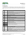
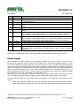
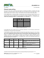
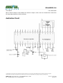
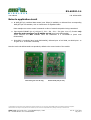
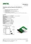
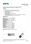
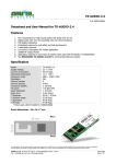
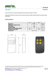
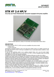
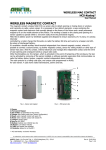
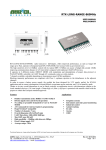
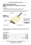
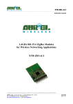
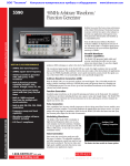
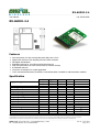
RX-AUDIO-2.4
---------------------------------------------------------------------------------------------------------------------------------------------------
User Manual
P.N. 650201005G
RX-AUDIO-2.4
Features
Non-compression for high sound quality with delay time 0.5 ms.
Digital audio with 44.1 KHz sampling rate and 16-bit resolution.
FSK digital demodulation
Embedded antenna for cost-effect and fast development
Improved performance in harsh environment by antenna diversity
8 selectable channels
Low power consumption for mobile application
To be used with 650201004G TX-AUDIO-2.4 and 650201062G TX-AUDIO-2.4/AE transmitter modules
Specification
Supply Voltage
Current Consumption
Operating temperature
Modulation
Frequency range
Channel number
Channel spacing
Frequency stability
Sensitivity
Output impedance
Output level
Response
Dynamic Range
Separation
SN radio
Board dimensions
Min
4,9
2,2
Typical
5,0
Max
5,1
3,6
+60
Unit
VDC
VDC
mA
°C
2483.5
MHz
65
-10
Notes
headphones side
FSK
2400
8
9
-100
+100
-83
12
1,8
20.000
20
92
80
87
47 x 32 x 7
MHz
KHz
dBm
ohm
VPP
Hz
dB
dB
dB
mm
headphones side
headphones side
(1)
(1)
(1)
(1)
NOTE 1: When used with TX-AUDIO-2.4 650201004G
Le caratteristiche tecniche possono subire variazioni senza preavviso. AUREL S.p.A non si assume la responsabilità di danni causati dall’uso improprio del dispositivo.
Technical features are subject to change without notice. AUREL S.p.A. does not assume responsibilities for any damages caused by the device’s misuse.
--------------------------------------------------------------------------------------------------------------------------------------------------------------------AUREL S.p.A. Via Foro dei Tigli, 4 - 47015 Modigliana (FC) – ITALY
Rev. B – 07.10.2009
Pag 1 di 7
Tel.: +39.0546.941124 Fax: +39.0546.941660
RX-AUDIO-2.4
---------------------------------------------------------------------------------------------------------------------------------------------------
User Manual
P.N. 650201005G
Pin description
The RX-AUDIO-2.4 module can be ideally divided into two sections: the first oriented to be plugged with an
usual power supply (pin 1 to 20), the other optimized to meet the needs of portable devices (pin 21 to 36).
This is the reason why pins do not follow an usual ordering, but it's like having two devices arranged side by
side.
Pin
1
Name
PWR ON
2
MUTE
3
USER_BIT
4
5
FORMAT
OB
6
TACT_SW
7
8
VCC
DAC_L
9
10
GND
DAC_R
11
12
13
14
15
16
17
18
SW2
SW1
SW0
ID3
ID2
ID1
ID0
CH_MODE
19
20
Description
The level is logical high (at least 2.7V) 1-2 seconds after DC power supply is applied
to the module. It can be used to turn on the audio power amplifier to prevent popnoise turning on RX module (2)
The voltage level equals Vsupply (see Power Supply section) while receiving a radio
signal and logical low during poor receiving condition. It can be used for receiving
indicator, extra noise reduction when TX is turn off, etc… (2)
Data stream output, correspondent to the data stream applied to USER_BIT signal of
TX module (Max data rate: 5Kbps) (2)
Pull down to use scrambling digital audio (internal pull up)
Forced down enables Out of Band channel, recommended for testing purposes only
(nternal pull up)
Switch / scan / automatically scan channel, requires a low impulse (internal pull up),
see channel mode setting table for details (3)
5 ± 0.1VDC
Left channel of audio output from DAC directly. Useful to feed audio signal to a
power amplifier. A DC blocking capacitor (>10 uF) should be added, unless the load
is high-impedance than 10Kohm
Ground
Right channel of audio output from DAC directly. Useful to feed audio signal to a
power amplifier. A DC blocking capacitor (>10 uF) should be added, unless the load
is high-impedance than 10Kohm
In DIP MODE used to manually select the channel (internal pull up),
see DIP MODE selection table for details
ID selection, low active (internal pull up). Only receiver(s) with the same transmitter
ID combination can reproduce transmitted audio.
Channel mode setting: ‘0’ for DIP mode, ‘1’ for TACT mode (internal pull up), see
channel mode setting table for details.
TACT_SCAN TACT mode switch / scan channel: ‘0’ to switch channel by channel each lowimpulse is applied on TACT_SW pin; ‘1’ to automatically search transmission channel
when a low-impulse is applied on TACT_SW pin (internal pull up), see channel mode
setting table for details.
CT_INU
Automatically scan procedure enable: ‘0’ to start channel scan when a low-impulse is
applied to TACT_SW; ‘1’ to automatically search channel when poor receiving
condition is verified (internal pull up), see channel mode setting table for details.
NOTE 2: PWR ON, MUTE and USER_BIT outputs can each deliver a current up to 25mA.
NOTE 3: Input is catched on the TACT_SW rising edge, we recommend to apply a negative pulse with a duration of at least 10ms.
Le caratteristiche tecniche possono subire variazioni senza preavviso. AUREL S.p.A non si assume la responsabilità di danni causati dall’uso improprio del dispositivo.
Technical features are subject to change without notice. AUREL S.p.A. does not assume responsibilities for any damages caused by the device’s misuse.
--------------------------------------------------------------------------------------------------------------------------------------------------------------------AUREL S.p.A. Via Foro dei Tigli, 4 - 47015 Modigliana (FC) – ITALY
Rev. B – 07.10.2009
Pag 2 di 7
Tel.: +39.0546.941124 Fax: +39.0546.941660
RX-AUDIO-2.4
---------------------------------------------------------------------------------------------------------------------------------------------------
User Manual
Pin
21
22
Name
GND
DC_IN
23
24
GND
CH_R
25
26
GND
CH_L
27
DAC_L
28
DAC_R
29
30
31
32
AMP_R
AMP_L
GND
TACT_SW
P.N. 650201005G
Description
Ground
Headphone amplifier supply voltage, if less than 2.2VDC the receiver goes in “batterylow” protection mode
Ground
Right channel audio headphone driver. A DC blocking capacitor (>100 uF) should be
added.
Ground
Left channel audio headphone driver. A DC blocking capacitor (>100 uF) should be
added.
Left channel of audio output from DAC directly. Useful to feed audio signal to a
power amplifier. A DC blocking capacitor (>10 uF) should be added, unless the load
is high-impedance than 10Kohm (same as pin 8, which is internally connected).
Right channel of audio output from DAC directly. Useful to feed audio signal to a
power amplifier. A DC blocking capacitor (>10 uF) should be added, unless the load
is high-impedance than 10Kohm (same as pin 10, which is internally connected).
Headphone driver Right channel input (volume adjust)
Headphone driver Left channel input (volume adjust)
Ground
Switch / scan / automatically scan channel, requires a low impulse (internal pull up),
see channel mode setting table for details (same as pin 6, which is internally
connected) (3)
NOTE 3: Input is catched on the TACT_SW rising edge, we recommend to apply a negative pulse with a duration of at least 10ms.
All inputs are in CMOS logic, with Vsupply/2 threshold value to discriminate between high or low level.
Power Supply
The RX-AUDIO-2.4 receiver module has two alternative supply ways: 5V to VCC (pin 7) or 2.2 to 3.6V to
DC_IN (pin 22). Whatever source is used, the circuit make use of an internally regulated voltage, Vsupply, of
3V. The low voltage power supply input DC_IN (pin 22) allows to connect a portable device and acquire the
power from that. When the radio signal is too weak to be played, a circuit protection is activate to safeguard
energy consumption and unnecessary battery current drainage, at the same time audio outputs AMP_R and
AMP_L are brought to logic level low. The receiver module operates up to a lower limit voltage of 1.6 V on
pin DC_IN, below which it turns off. To return to have a running device DC_IN must be brought to a voltage
level sufficient to restart the microcontroller on board (about 3V).
With a 5V power on VCC input (pin 7) there is no control of the supply voltage, and if it drops too low (below
3V) none audio get out from the outputs but only a DC voltage which comes from the power supply.
The ripple power immunity of audio outputs signals (corresponding to a voltage that varies between 2.2 and
3.6V) is:
• 100mV ripple voltage at 100Hz, with volume up to the limit, generates an output variation of 10mVPP
• 700mV ripple voltage at 100Hz, with volume up to the limit, generates an output variation of 20mVPP
Le caratteristiche tecniche possono subire variazioni senza preavviso. AUREL S.p.A non si assume la responsabilità di danni causati dall’uso improprio del dispositivo.
Technical features are subject to change without notice. AUREL S.p.A. does not assume responsibilities for any damages caused by the device’s misuse.
--------------------------------------------------------------------------------------------------------------------------------------------------------------------AUREL S.p.A. Via Foro dei Tigli, 4 - 47015 Modigliana (FC) – ITALY
Rev. B – 07.10.2009
Pag 3 di 7
Tel.: +39.0546.941124 Fax: +39.0546.941660
RX-AUDIO-2.4
---------------------------------------------------------------------------------------------------------------------------------------------------
User Manual
P.N. 650201005G
Channel mode setting
There are two main ways to change the audio channel in use between 8 availables: a manually mode, called
DIP MODE, or automatic switches, called TACT MODE. When CH_MODE (pin 18) input signal value is ‘0’ DIP
MODE is selected, when it’s value is a logic ‘1’ TACT MODE is active (see channel mode setting table).
In DIP MODE channel is selected manually by setting SW2, SW1 and SW0 input signals. Inputs are low
active and SW2 is the most significant bit of the hexadecimal negated combination: it means that a 1-1-1
configuration correspond to channel ‘0’, at lowest frequency; 1-1-0 is for the channel ‘1’, immediately above,
until to 0-0-0 that select the channel ‘7’, at higher frequency, as in table below:
channel SW2 SW1 SW0 Carrier frequency
7
0
0
0
2473 MHz
6
0
0
1
2464 MHz
5
0
1
0
2455 MHz
4
0
1
1
2446 MHz
3
1
0
0
2437 MHz
2
1
0
1
2428 MHz
1
1
1
0
2419 MHz
0
1
1
1
2410 MHz
NOTE 4: SW2, SW1 and SW0 inputs are internally pulled up.
Table 1 – DIP MODE selecting channel
In DIP MODE SW2, SW1 and SW0 inputs are continuously monitored, so is not necessary to switch values
simultaneously or doing any kind of syncronization.
In TACT MODE is possible to change channel by the single input signal TACT_SW (on pin 6 or 32). The way
used to do the change depends by the settings of two more input signals: TACT_SCAN (pin 19) and CT_INU
(pin 20). The configuration of that three inputs select in which mode the channel will change after the low
impulse on TACT_SW: switching channel by channel until reaching the desired transmission (useful
especially when there are more broadcasts on multiple channels), starting an automatic search through all
channels to find the only one transmitting, or automatically start a search of the transmitting channel when
poor receiving condition are detected.
Channel
CH_MODE TACT_SCAN
change mode
(pin 18)
(pin 19)
DIP
GND
x
CT_INU
(pin 20)
x
TACT
x
GND
x
TACT
SCAN
TACT
AUTO SCAN
x
x
GND
x
x
x
Function
Manual mode: set SW2, SW1 and SW0 to choose
the channel
Switch channel by channel when each lowimpulse is applied to TACT_SW (pin 6)
Automatically search channel when low-impulse is
applied to TACT_SW (pin 6)
Automatically search channel when poor receiving
condition
NOTE 3: X indicate a floating pin, internally pulled up.
Table 2 – Channel mode setting table
Le caratteristiche tecniche possono subire variazioni senza preavviso. AUREL S.p.A non si assume la responsabilità di danni causati dall’uso improprio del dispositivo.
Technical features are subject to change without notice. AUREL S.p.A. does not assume responsibilities for any damages caused by the device’s misuse.
--------------------------------------------------------------------------------------------------------------------------------------------------------------------AUREL S.p.A. Via Foro dei Tigli, 4 - 47015 Modigliana (FC) – ITALY
Rev. B – 07.10.2009
Pag 4 di 7
Tel.: +39.0546.941124 Fax: +39.0546.941660
RX-AUDIO-2.4
---------------------------------------------------------------------------------------------------------------------------------------------------
User Manual
P.N. 650201005G
After a channel change in TACT MODE, the module is ready to work on the new channel after 100ms from
the rising edge detected on TACT_SW input.
Application Circuit
Le caratteristiche tecniche possono subire variazioni senza preavviso. AUREL S.p.A non si assume la responsabilità di danni causati dall’uso improprio del dispositivo.
Technical features are subject to change without notice. AUREL S.p.A. does not assume responsibilities for any damages caused by the device’s misuse.
--------------------------------------------------------------------------------------------------------------------------------------------------------------------AUREL S.p.A. Via Foro dei Tigli, 4 - 47015 Modigliana (FC) – ITALY
Rev. B – 07.10.2009
Pag 5 di 7
Tel.: +39.0546.941124 Fax: +39.0546.941660
RX-AUDIO-2.4
---------------------------------------------------------------------------------------------------------------------------------------------------
User Manual
P.N. 650201005G
Notes to application circuit
At USER_BIT pin, serialized data stream (max. 5Kbps) is available, as delivered from corresponding
USER_BIT pin of transmitter, with no interference on digitalized audio.
Data examples are remote control commands or titles of musical composition being transmitted.
Input signals FORMAT (pin 4), OB (pin 5), ID3 – ID2 – ID1 – ID0 (pins 14 to 17) function only
when the used transmitter is a TX-AUDIO-2.4/AE (Aurel code 650201062G).
Those functions are NOT available when the transmitter is a TX-AUDIO-2.4 (Aurel code
650201004G).
RX AUDIO 2.4 modules (Aurel code 650201005G), delivered prior of mid 2008, use ONLY pins 1 to
20 (pins 21 to 32 are NOT connected)
Now the Aurel code 650201004G corresponds by default to the second series of the module.
First series (pins 1 to 20 only)
Second series (full pin-out)
Le caratteristiche tecniche possono subire variazioni senza preavviso. AUREL S.p.A non si assume la responsabilità di danni causati dall’uso improprio del dispositivo.
Technical features are subject to change without notice. AUREL S.p.A. does not assume responsibilities for any damages caused by the device’s misuse.
--------------------------------------------------------------------------------------------------------------------------------------------------------------------AUREL S.p.A. Via Foro dei Tigli, 4 - 47015 Modigliana (FC) – ITALY
Rev. B – 07.10.2009
Pag 6 di 7
Tel.: +39.0546.941124 Fax: +39.0546.941660
RX-AUDIO-2.4
---------------------------------------------------------------------------------------------------------------------------------------------------
User Manual
P.N. 650201005G
Application information
Designing the transmitter module in wireless speakers and headphones, must pay attention to the following
considerations:
Do not let any metal objects too close to antenna
Figure 1 - Antenna area (marked by diagonal lines)
Receiver module must be kept over 3 cm away from speakers to avoid magnetic interference
Power supply to receiver module must be independent, separate from the power of amplifier
Avoid to put any cable or circuit nearby antenna (1-2 cm)
Le caratteristiche tecniche possono subire variazioni senza preavviso. AUREL S.p.A non si assume la responsabilità di danni causati dall’uso improprio del dispositivo.
Technical features are subject to change without notice. AUREL S.p.A. does not assume responsibilities for any damages caused by the device’s misuse.
--------------------------------------------------------------------------------------------------------------------------------------------------------------------AUREL S.p.A. Via Foro dei Tigli, 4 - 47015 Modigliana (FC) – ITALY
Rev. B – 07.10.2009
Pag 7 di 7
Tel.: +39.0546.941124 Fax: +39.0546.941660