1
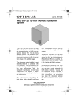
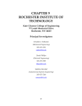
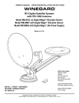
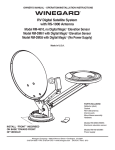
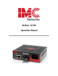
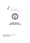
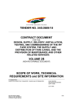
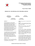
CellSense
User’s Manual
Cell Voltage Monitor (CVM)
October 2007
Contents
Introduction
Application
Technology
CVM schematics
CVM specifications
Installation
Assembly
Connecting the powder supply
Connecting the CAN bus
Allocating a Node number
Baptizing procedure
Connecting the stack
Connecting the alarm relay
Connections in case of more stacks
Basic settings
Advanced settings and possibilities
Message type : detailed or summary
Extra idle time
Stack ID
Led and relay
Time counters
CVM/CAN protocol
Software
References
CellSense User’s Manual
June 2006
3
3
3
4
5
5
5
6
6
6
6
7
7
7
8
9
9
9
9
9
10
11
14
15
2/15/
Introduction
Cell Voltage Monitor (CVM) has been designed to measure all individual cell voltages
of a fuel cell stack. The measurements are processed into a summarizing message, that is
sent over a serial connection to a system controller, allowing to react on decreasing cell
voltages.
Application
This concept is meant to be part of a control and monitoring circuit of a commercial fuel
cell stack. The accuracy and the rate of the measurements are based upon this target,
resulting in a significant cost reduction compared to classic cell voltage measuring
systems.
The performance of the system allows to obtain polarisation curves of individual cells or
to detect low cell voltages in an early stage. Detection of low voltages can be followed
by e.g. increasing gas flows, or in worse cases, switching off the load.
Possible advantages:
• lower gas stochiometry (lower λ)
• higher availability, better quality of electric power
• less chance of damage
• increased life expectancy
• fast diagnosis in case of damage
Technology
A detailed description of the technology can be found in the patent text.
The system consist of two components : the voltage scanning unit and the central unit.
The voltage scanning unit (VSU) measures the voltages of 4 cells. Any number of VSUs
are connected through a galvanic isolation to a common data bus and a voltage supply
line. The central unit takes care of the data communication with the VSUs, the power
supply to the VSUs and the communication to the outside world, e.g. via CAN bus.
The central unit can pre-process the measured data, so that only relevant data will be
sent, limiting the data stream on the communication bus and by that also the work load
on the receivers of the data. The pre-processing is completely implemented in software
and therefore it can be adapted according to the application. The pre-processing sends a
CAN message with the maximum, the minimum and the average cell voltage and the
corresponding numbers of the cells where the maximum and minimum voltage occur and
it controls two digital outputs pointing out an alarm status.
CellSense User’s Manual
June 2006
3/15/
CVM schematics
Data
bus
Power
bus
Stack
VSU
Main
Controller
COM PORT
PWM
Internal
comm. port
Figure 1 : Schematics
CellSense User’s Manual
June 2006
4/15/
CVM specifications
Parameter
Supply voltage
Power consumption
Measuring range
Accuracy
Resolution
Conversion rate
Maximum number of cells
Galvanic isolation between cell groups and central unit
Galvanic isolation over power supply
Galvanic isolation of the CAN bus
Table 1: Specifications
Value
20..30 VDC
1 W + 50 mW / cell
-0,1...1,1V
± 10 mV
2,5 mV
900 cells / sec.
270
300 VDC
1500 VDC
2500 VAC
Installation
Programming
connector
Alarm LED
CAN bus
NO Com NC
Relay
+24V GND
Power spply
Figure 2 : Connections
Assembly
The system is delivered in order to be mounted on a fuel cell stack and can be considered
as a part of the stack.
Fuel cells can generate dangerous voltages. In order to avoid dangerous
situations, the assembly must be carried out when the stack has no
voltage. The assembly has to be carried out by skilled persons able to
detect this safe situation.
The dimensions of the printed circuit board (PCB) fit to a stack with 73 – 76 cells.
Smaller stacks down to 28 cells can be equipped with the same system, cutting off the
PCB between two VSU’s: minimum 7 VSU’s have to be kept intact. The two long sides
of the PCB have a strip (5 mm) in order to assemble the PCB on top of the stack.
The assembly must guarantee protection against:
CellSense User’s Manual
June 2006
5/15/
* radiation/reception of EMI, also via cables
* mechanical stress
* contact or electric shock
* isolation failure in case of high voltages, especially when connecting more stacks in
series
Connecting the power supply
Power to the system is supplied by a 24 VDC isolated power supply or grid adaptor. The
connection is on the terminals of the PCB. Several CVMs may be connected to one
power supply provided isolation limits are not exceeded.
Connecting the CAN bus
The CAN bus is connected by a DB9
connector. The connections are
according to the recommendations
CiA DS 102.
1
2
3
4
5
6
7
8
9
CAN_L
CAN_GND
CAN_SHLD
The power supply of the galvanic
GND
isolation of the CAN bus can be
CAN_H
passed from an external source over Figure 3 :DB9 CAN
this connector. In this case the jumper bus connector
CAN_V+
at the CAN interface should be
removed.
In the other case the
galvanic isolation will be powered from the CVM and no supply lines should be
connected.
Allocate Node number
The CVM communicates over a CAN bus with its own protocol that can coexist with
CANOpen. This allows connecting several participants (nodes) on the bus, such as other
CVM’s, invertors, PLCs, sensors, etc.. Every participant (node) receives a node number
between 1 and 127. In order to adjust the node number of the CVM, a point to point
CAN connection has to be made and the node number has to be adjusted following the
CVM/CAN protocol (see lower). As soon as the CVM has received its node number it
can be connected to a CAN bus
The supplied LabView interface can be used to adjust the
node number.
Baptizing procedure
Before connecting a stack every VSU has to receive an unique (within one CVM)
address. This address is an increasing number between 0 and 220. The VSU of the first
cell group (cell 1 to cell 4), receives the address 0, the VSU of cells 5 to 8 receive address
1, etc. Adjusting the addresses is called ‘baptizing’ and is necessary to be able to make
the correct link between each VSU and its physical connection to the stack.
CAN communication has to be active. Clear all existing addresses in the VSU’s (function
code 9) and start the baptizing procedure (function code 7) Supply a voltage of 2,2 – 4,5
V between two terminals of the first VSU . As soon as this voltage has been measured by
CellSense User’s Manual
June 2006
6/15/
the VSU, this VSU receives address 0. This is
reported over the CAN bus (function code 8), and
the first VSU has been baptized. Move the voltage
supply to the following VSU for baptizing. After
each confirmation over the CAN bus the supply
voltage can be moved to the next VSU.
Scrupulously respect the physical sequence of the
VSUs. If the last VSU has been baptized, the
baptizing procedure should be stopped (function
code 7) and one can start connecting the stack.
In the CVM every cell has a shunt resistance of 100 Ohm. In the worst case the supply
voltage has to have the capacity to deliver 45 mA (4,5 V / 100 Ohm), in the best case 8
mA (2,2 V / 300 Ohm) need to be delivered. The voltage source can be a 9V battery with
, at least, a suitable resistance (470 Ohm in case of 8 mA).
The accompanying LabView interface can be used for
baptizing the VSU’s (‘Baptize’ tab); the progress of the
process can be followed interactively.
Figure 4: Baptizing
Connecting the stack
-stack +cell1 +cell2 +cell3 +cell4 +cell5....
Figure 5 :stack connections
The negative terminal of the stack must be connected to the first connection (closest to
the corner of the print) of the first VSU. This VSU has 5 connections. The remaining four
connections are the positive terminals of the first four cells of the stack. All following
VSU’s have four connections for the positive terminal of each of the four cells of a group
of cells.
Connecting the alarm relay
The alarm relay switches if the voltage of at least one cell drops below a set value and
remains low for several consecutive measurement cycles (function code 13 to 15). A NO
CellSense User’s Manual
June 2006
7/15/
(normally open) and NC (normally closed) contact are available. The operating mode of
the relay can be programmed to :
1. be exited in case
a. of fault
b. of no fault
2. change state when
a. a cell voltage becomes low only
b. a cell voltage becomes low and an internal fault was detected
3. signal a low cell voltage when the lowest cell voltage
a. drops below a fixed threshold
b. deviates from the average cell voltage
These options allow the user to set up the system and use the relay for fail-safe operation.
Connections in case of more stacks
Fuel cells connected in series can generate dangerous voltages, even if
the stack that one is working on, has no voltage. In order to avoid
dangerous situations the assembly has to be carried out if the complete
installation has no voltage and has to be carried out by persons with the
necessary knowledge to make sure that the work situation is safe.
If several stacks are connected in series and each stack has its own CVM, differences in
potential occur over the different CVM’s. The magnitude of these potential differences is
a function of the number of stacks in series and can be present over the isolation of the
power supply, the CAN bus and, potentially, the alarm relay. The user should take care of
the fact that the different CVMs should not have the same potential via the power supply.
In this case, each CVM needs its own galvanic isolated power supply. An individual
adaptor with the corresponding isolation potential will be sufficient.
Basic settings
Before doing the first test at least the number of cells for a stack (function code 1) and
the offset voltage of the A/D converters in the VSU’s (function code 6) have to be set.
In case of a stack with 50 cells, one has to send following CAN message to the CVM:
ID = 600 + NN
set 50 cells
func.c.
01h
data 1
0
data 2
32h
data 3
0
Table 2 : set the number of cells via the CAN bus
Each A/D converter has an offset voltage that allows measuring negative voltages. This
voltage is in principle 400 mV, but can vary slightly between different VSU’s. Therefore
this offset can be individually programmed. It consists of the sum of two parts: a
common part (e.g. 350 mV) and an individual part (e.g. 47 mV, 50 mV, 49 mV,….) for
each VSU. The common part should be selected in a way that each individual part is
between 0 mV and 250 mV.
CellSense User’s Manual
June 2006
8/15/
The CVM can be instructed to calculate the individual offsets. To do this it is required
that all cell voltage inputs are at the same potential. If the CVM is equipped with cell
shunt resistors, this can be achieved by leaving the terminals unconnected. In the other
case all terminals should be shorted to each other. It is necessary to wait 10 seconds for
the cell voltage inputs to stabilize at 0V. Then the CAN message can be sent to instruct
the CVM to calculate and store the offsets.
Initially the common part is set to 350 mV and all individual are automatically calculated
by sending following two CAN messages to the CVM
ID = 600 + NN
set 350mV
calculate offsets
func.c.
06h
06h
data 1
FFh
FDh
data 2
1
data 3
5Eh
Table 3 : Set offsets via the CAN bus
Additional settings are explained in more detail in the description of the protocol.
The supplied Labview interface can be used to set the
number of cells the offsets (‘Setup’ tab)
Advanced settings and possibilities
Message type: detailed or summary
The CVM measures all cell voltages almost simultaneously (less than 300 µsec). The
measurements are than read from the VSU’s.
As soon as all measurements have been read (one cycle) a CAN message is sent with
ID=180+node number containing the minimum, maximum and average cell voltage and
the cells in which the minimum and maximum voltages occurred.
It is also possible to obtain a detailed picture of all cell voltages by programming the
CVM to send a message with all individual cell voltages after reading each VSU
(function code 1). These messages have a lower priority, ID=280+node number.
Retrieving these details significantly slows down the system and generates a lot of data
traffic on the CAN bus.
Extra idle time
In order to limit CAN bus traffic or to slow down the conversion rate of the CVM, an
additional delay of 2 to 425ms can be programmed after each conversion. The CVM will
not perform any action during this delay.
Stack ID
Each CVM belongs to a stack. An individual identification of the stack and CVM can be
stored in the CVM (function code 12) and can be read (function code 11). The maximum
length of this identification is 7 characters.
Led and relay
A red LED and a relay are provided for detecting low cell voltages. The operation mode
and the cell voltage for switching the LED and the cell voltage for switching the relay
can be set each (function code 15) or read (function code 13 and 14). The LED operation
is similar to the relay operation as explained in “connecting the stack” except that it
CellSense User’s Manual
June 2006
9/15/
changes state after only one error was detected. On the other hand the relay switches only
if and error condition persists during a programmed number of consecutive cycles. A
relay contact can be e.g. part of a emergency shut down circuit or can be part of the
signal enabling the load.
Time counters
The CVM includes two time counters counting the seconds that the stack is operated
under open circuit conditions and under load condition. These conditions are recognised
by comparing the average cell voltage to two thresholds.
Ucel_average > Uopen_circuit_threshold : the open-circuit counter
increments
Uoperation_threshold < Ucel_average < Uopen_circuit_threshold : the in-operation counter
Ucel_average < Uoperation_threshold
increments
: no counter increments
The counters can be reset or preset via the CAN bus interface.
The counters are saved in permanent memory every 256 seconds or when Ucel_average
drops below Uoperation_threshold. Interrupting the power supply to the CVM while the
fuels cell stack is in operation may cause loss of maximum 256 seconds.
Whenever the sum of the counters reaches approximately 5000 hours or any of its
multiples, an memory refresh procedure should be executed. The user should request this
procedure by sending an appropriate CAN message (function code 21) to the CVM at a
convenient moment (e.g. after shutting down the fuel cell stack). The procedure needs 1
second to complete. While it is running, the CVM can not operate normally.
The accompanying LabView interface can be used to set
and read the stack ID (‘Stack ID’ tab), to set an read
alarm levels (‘Alarms’ tab) and to set and read time
counters (‘Hour counter’ tab).
CellSense User’s Manual
June 2006
10/15/
CVM/CAN protocol
The protocol used by the CVM on the CAN bus can coexist with CANOpen. With
CANOpen each node in the network requires an unique node number (NN) between 1
and 127. This is also the case for the CVM. The message IDs used by a CAN node, are
derived from the NN (see next table). In addition one fixed message ID is used to set the
NN of a node. Therefore this can only be done in a point-to-point connection.
CAN ID
direction, length en frequency
Contents
0
Receive 2 bytes
180 + NN
(hex)
Send 8 bytes
at the end of e cycle
280 + NN
(hex)
Send 8 bytes
After reading of one cell
group
Send 8 bytes
Set node number :
Byte 0 : 10(hex) : program node number
Byte 1 : NN for one CVM
Send summary of cell voltages :
Byte 0 : cell number met highest voltage
Byte 1..2 : highest voltage [mV]
Byte 3 : cell number met lowest voltage
Byte 4..5 : lowest voltage [mV]
Byte 6..7 : average voltage [mV]
Send details of all cell voltages :
Byte 0 : cell group to which data belongs
Byte 1..4 : cell voltages as 4 x 12 bits [mV](2)
Send status and settings :
Byte 0 : function code
Byte 1..7 : see next table
Receive settings :
Byte 0 : function code
Byte 1..7 : see next table
580 + NN
(hex)
600 + NN
(hex)
Receive 8 bytes
Table 4 : Different CAN messages
The messages with ID-180+NN and 280+NN can be compared with the PDOs defined in
CANOpen. The other messages, 580+NN and 600+NN are comparable with SDOs. In
these messages the first byte of the data block is reserved for a function code, that
determines the contents of the remaining bytes of the data block. Next table specifies
what function codes are defined and how to interpret the contents of the data block.
Rows with <-- as direction (from CVM to PC or PLC) are related to messages with ID =
580+NN, the remaining are related to messages with ID = 600+NN.
Function code
(Byte 0)
0
status message
1
--> CVM
PLC <-<-spontaneous
in case of error
set number of
cells, data
stream type and
additional delay
CellSense User’s Manual
-->
Contents of van byte 1..7(filled up with 00s)
Byte 1 :failure code
0 = no failure
1 = no VSU found
2 = data line continuously high
3 = data line continuously low
4 = no data received or failure in data van 1 VSU
Byte 2 : cell group (VSU) with last failure
Byte 3 : number measured cell groups
Byte 1..2 : number of cells in system
Byte 3 : 0=send only min/max.. (ID=180+NN)
1=send each cell data (ID=180+NN en
ID=280+NN)
Byte 4 : additional delay after measurement cycle
June 2006
11/15/
2
2
request number
of cells, data
stream type and
additional delay
reply number of
cells, data
stream type and
additional delay
-->
<-reply to
function code
2
4
5
request Voffset
reply Voffset
6
set Voffset
7
baptize VSUs
-->
8
baptized VSU
9
reset all VSU to
default
request stack ID
<-at detection of
baptizing
conditions
-->
10
0Ah
11
0Bh
reply stack ID
12
0Ch
13
0Dh
14
0Eh
set stack_ID
15
0Fh
set alarm trip cell
voltage
16
10h
17
11h
request software
version
reply software
version
19
13h
20
14h
set time counter
thresholds
request time
counter
thresholds
reply time
counter
thresholds
20
14h
request alarm
trip cell voltage
reply alarm trip
cell voltage
-->
<-reply to
function code
4
-->
Byte 1..2 : number of cells in system
Byte 3 : 0=send only min/max.. (ID=180+NN)
1=send each cell data (ID=180+NN en
ID=280+NN)
Byte 4 : additional delay after measurement cycle
Byte 1 : cell group number (5)
Byte 1 : cell group number (5)
Byte 2..3 : Voffset
Byte 4..5 : Vsupply in 0.01V
Byte 1 : cell group number (5)
Byte 2..3 : Voffset in mV
Byte 1 : 0=stop procedure
1=start procedure
Byte 1 : cell group number of baptized VSU
Byte 1..4 : AAh 55h 33h CCh
-->
<-reply to
function code
10
-->
Byte 1..7 : ID in ASCII
Byte 1..7 : ID in ASCII
-->
<-reply to
function code
13
-->
Byte 1..2 : min cell voltage for LED on [mV]
Byte 3..4 : min cell voltage for relay on [mV]
Byte 5 : number of failures before relay switches
Byte 6 : alarm operating mode (4)
Byte 1..2 : min cel voltage for LED on [mv]
Byte 3..4 : min cell voltage for relay on [mv]
Byte 5 : number of failures before relay switches
Byte 6 : alarm operating mode (4)
-->
<-reply to
function code
16
-->
Byte 1 : major version number
Byte 2 : minor version nummer
Byte 1..2 : Vopen circuit threshold [mV]
Byte 3..4 : Voperation threshold [mV]
-->
<-reply to
function code
20
CellSense User’s Manual
Byte 1..2 : Vopen circuit threshold [mV]
Byte 3..4 : Voperation threshold [mV]
June 2006
12/15/
21
15h
21
15h
request time
counter values
reply time
counter values
22
16h
set time counter
values
-->
<-reply to
function code
20
-->
Byte 1 : counter number
1 = open circuit counter, 2 = operation counter
Byte 1 : counter number
Byte 2..5 : counter value in seconds
Byte 1 : counter number
Byte 2..5 : counter value in seconds
Table 5 : protocol on the CAN bus
(2) 4x12 bits refers to a compression method in which four 12bit numbers are
concatenated into six data bytes
(3) Cell groups are numbered between 0 en 220 (00h to DCh).
(4) The alarm operating mode is a byte composed or interpreted as eight bits with these
functions :
bit 0 : relay coil excitation
0 = relay coil excited if fault
1 = relay coil excited if no fault
bit 1 : relay fault definition
0 = cell voltage only
1 = cell voltage and internal function
bit 2 : relay cell voltage fault definition
0 = compare to constant
1= compare to average cell voltage
bit 3 : not used
bit 4 : led on
0= led on if fault
1= led on if no fault
bit 5 : led fault definition
0 = cell voltage only
1 = cell voltage and internal function
bit 6 : led cell voltage fault definition
0 = compare to constant
1= compare to average cell voltage
bit 7 : not used
(5) Voffset consists of the sum of two components: a common part for all cell groups and
an individual part for each cell group. Cell group number FFh refers to the common
component. Cell group number FEh collectively refers to all individual parts. Cell
group number FDh instructs the CVM to automatically calculate and store the
individual offsets.
CellSense User’s Manual
June 2006
13/15/
Software
The CVM contains following software :
• microcontroller firmware on each VSU :
o converts individual cell voltages
o communicates with the main controller
• microcontroller firmware on the main controller of the CVM
o communicates with de VSUs
o processes the data of the VSUs into easily interpretable information
o communicates on the CAN bus
o holds all measurements
• LabView driver example (PC, Windows, LabView 7.1 required)
o can be used as user interface to the CVM over the CAN bus for starting
up, commissioning and for adjusting settings
o can be used as a driver or as an example for data-acquisition code in
Labview with the CVM
The Labview interface consists of a number of tab sheets. The functionalities of the
interface with the CVM are grouped per sheet. The relation to the earlier described
functions and possibilities is unambiguous. The diagram (source code) can be used as-is
or can serve as inspiration to build, if desired, your own interface or data-acquisition.
Moreover the interface is an illustration of the protocol description that can be useful
when programming of an interface for other hardware, e.g. a PLC.
In order to communicate via the LabView interface with the CVM, first the node number
of the CVM to which we want to connect, has to be set on the main screen. In this way
one can communicate with one single CVM, even though several CVMs are connected to
the same CAN bus. As soon as the node number has been set the functions on the sheets
can be used and they relate only to the selected CVM.
Selecting
the node
number
Figure 6 : LabView interface example
CellSense User’s Manual
June 2006
14/15/
It is recommended not to set the CVM to sending individual cell voltages (detailed data
stream type) for general use, especially in the case that several CVMs are connected to
the same bus. The large amount of data will inevitable lead to overloading the CAN bus.
References
[1] NI-CAN Hardware and Software Manual, National Instruments
Using CAN in LabView
[2] http://www.can-cia.org/
Official CANOpen standards
[3] http://atlas.web.cern.ch/Atlas/GROUPS/DAQTRIG/DCS/CANINFO/canproto.html
Practical CANOpen standards
[4] Controller Area Network, a Serial Bus System – Not Just for Vehicles, ESD gmbh
CAN bus documentation: principle and operation
CellSense User’s Manual
June 2006
15/15/