1
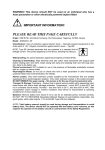
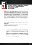
TL6000 Remote Users Manual Intercomp Co. 3839 County Road 116 Medina, MN 55340, U.S.A. (763)-476-2531 1-800-328-3336 Fax: 763-476-2613 www.intercompcompany.com Manual #: 700173-G TL6000 Remote, Users Rev G, June 2009 Table of Contents INTRODUCTION .......................................................................................................................................................3 SPECIFICATIONS .........................................................................................................................................................3 Controls................................................................................................................................................................3 Electrical..............................................................................................................................................................3 Range ................................................................................................................... Error! Bookmark not defined. Environmental......................................................................................................................................................3 Physical................................................................................................................................................................3 Radio (applies to wireless versions only).............................................................................................................3 OPERATIONS.............................................................................................................................................................4 OPERATING PRACTICES..............................................................................................................................................4 DISPLAY ....................................................................................................................................................................5 Multiple Channel Display ....................................................................................................................................5 CONTROLS.................................................................................................................................................................6 ON/OFF ...............................................................................................................................................................6 MODE ..................................................................................................................................................................6 PRINT.................................................................................................................................................................................... 7 AUTO OFF ............................................................................................................................................................................ 7 SERIAL DATA OUT............................................................................................................................................................. 7 BAUD RATE......................................................................................................................................................................... 8 SCALES ................................................................................................................................................................................ 8 2nd Remote ............................................................................................................................................................................. 8 ZERO....................................................................................................................................................................9 TARE ....................................................................................................................................................................9 PEAK....................................................................................................................................................................9 POWER/BATTERIES ....................................................................................................................................................9 SET POINT OUTPUT .....................................................................................................................................................9 MAINTENANCE.......................................................................................................................................................10 PERIODIC INSPECTION ..............................................................................................................................................10 Service Categories .............................................................................................................................................10 Inspection Requirements ....................................................................................................................................10 Removal from Service Criteria...........................................................................................................................11 CALIBRATION...........................................................................................................................................................11 ERROR MESSAGES ................................................................................................................................................12 SERIAL OUTPUT.....................................................................................................................................................13 SCOREBOARD ..........................................................................................................................................................14 HOW TO REACH INTERCOMP SERVICE.........................................................................................................15 "This document is the property of Intercomp Co. It contains material and information that is confidential and protected under federal and/or state trade secret, unfair competition, and copyright law. Any reproduction, use or disclosure without written permission from Intercomp Co. is prohibited". Page 2 of 15 TL6000 Remote, Users Rev G, June 2009 Introduction This manual contains specifications, operation instructions, and calibration instructions for Intercomp's model TL6000 tension link remote. Specifications Controls General: Display: Indicators: On/Off, Mode, Zero, Peak, Tare 5 digit LCD. 1.2” 9 display icons Electrical Batteries: Battery life: Auto off: Outputs: Inputs: 1 or 2 alkaline 9V cells. Cabled version: 300 hours on (2) batteries; 150 hours/battery Wireless version: 50 hours on (2) batteries; 25 hours/battery Low battery, or after adjustable time without use or motion. RS232, RS485, 2 Set Points (3.3V logic level) Wireless: up to 20 multiple channels Cabled: 2-way connection to a TL6000 scale. Environmental Humidity: Temperature: 10 to 95% Non-Condensing. Operating: +14°F to +104°F / -10°C to +40°C Storage: -40°F to +170°F / -40°C to +75°C Physical Dimensions: Weight: 7.1” x 5.7” x 2.8” / 18 x 14.5 x 7cm 2.6 lb / 1.2 kg (without cable) Radio (applies to wireless versions only) Radio frequency (US/Canada) Radio frequency (Europe) License requirements Range 902 -928 MHz, 100mW max output power, FHSS 869.7 - 870 MHz, 5mW max output power, FSK None. Pre-approved US/FCC, CAN/IC, EUR/EN 200’ / 60m indoor, 400’ / 120m line of sight WARNING: This equipment has been approved for mobile applications ! where the equipment should be used at distances greater than 20cm from the human body (with the exception of hands, wrists, feet, and ankles. Operation at distances less than 20cm is strictly prohibited. Page 3 of 15 TL6000 Remote, Users Rev G, June 2009 Operations Operating Practices Warning: The crane scale will be operated by qualified designated persons, trainees under the direct supervision of designated persons, maintenance and test personnel when in performance of their assigned duties, or lifting device inspectors. Warning: Do not exceed the rated load limit of the crane scale. Warning: The crane scale shall be applied to the load in accordance with the instruction manual. Warning: Prior to lifting the operator shall make sure that all ropes or chains are not kinked and if multiple lines are used they are not twisted around each other. Warning: Ensure that the load is correctly distributed for crane scale use. Warning: Ensure the temperature of the load does not exceed the maximum temperature limits of the crane scale. Warning: Ensure that swinging of the crane scale is minimized when positioning it over the load. Warning: Avoid any sudden acceleration of deceleration when moving the load. Warning: Do not allow the crane scale or the lifter to come into contact with any obstruction when moving the load. Warning: Do not operate the crane scale if it has damaged, malfunctioning or missing parts. Warning: Do not lift people with the crane scale. Warning: Do not lift suspended loads over people. Warning: Do not use the crane scale to pull side loads or to slide loads unless specifically authorized by a qualified person. Warning: Do not leave suspended loads unattended. Warning: Do not remove or obscure warning labels. Warning: Do not operate the crane scale without having read and understood the operating manual. Page 4 of 15 TL6000 Remote, Users Rev G, June 2009 Warning: Stay clear of suspended loads. Warning: Do not lift loads higher than necessary. Warning: Do not make alterations or modifications to the crane scale. Warning: Ensure all portions of the human body are kept clear of all device involved with the rigging during the lift. Display Multiple Channel Display The TL6000 Remote can display and operate up to 20 scales. The remote can display a specific scale, or it can display the total weight of the scales that you have chosen to be actively displayed. To control the multiple channel display, simultaneously press the MODE and TARE keys. The display will show “0101- Y” 01-no”. 01- Y” Y or “01-no 01-no “01Y means the weight of scale 01 is will be added to the total, “01-no 01-no” 01-no means the weight of scale 01 will not be added to total. Press the PEAK or ZERO keys to toggle between “Y Y” or “no no”, no then press the MODE and TARE keys to complete the setting for scale 01 and scroll to the next scale. The display will show “0202- Y” 02-no” Y or “02-no 02-no (if you have more than one scale in your system). Repeat the procedure explained above until you are finished with the last scale in your system. The TL6000 remote will return to displaying the total weight after you have scrolled through all of the scales in your system. The following diagram shows what was explained in this paragraph: Page 5 of 15 TL6000 Remote, Users Rev G, June 2009 total number of scales Displayed weight total XX- Y Using the diagram above as an example: If the total number of scales in the system is 4, then we have: Total weight (or displayed weight) = scale 01 + scale 03 + scale 04 01-y 02-No 03-y Controls ON/OFF Press this key to turn the remote on. The remote tests itself; when these tests have completed successfully, the system waits for the incoming signal. Press this key to turn the remote off. MODE Some of the internal parameters can be adjusted through the mode function. All other internal parameters are adjusted with the TL6000 tension link itself (see TL6000 tension link manual). There are 5 modes that are accessible: Print, Auto-off, Serial data output, Baud rate. Mode Description Notes Print AOFF S Out Print ticket Auto off Serial data out Baud baud rate SCLS scales 2nd r nd 2 remote Hold MODE to print 1 to 180 (min.) 0 = disable 0 = on demand print 1 = continuous 300, 600, 1200, 2400, 4800, 9600, 19000 Enter the total number of scales in your system set to ‘1’ if you have a second remote Default 60 0 9600 1 0 Press the MODE key to sequentially toggle through the modes. To edit a mode press and hold the MODE key until the display changes. The value can be changed by using the arrow keys: ↑ ↓ ← → MODE TARE PEAK ZERO Please see the information on the following pages for specific instructions on editing each mode. To save the information you edited, press and hold the MODE key until the display reads ‘Save Save’. Save Page 6 of 15 TL6000 Remote, Users Rev G, June 2009 PRINT This feature allows the net weight to be printed. See “Serial Data Out” section for more information. To print ticket: Press the MODE key until the display reads “Print Print”. Print Press and hold the MODE key until the display reads “Edit Edit”. Edit The net weight will be printed and the remote returns to normal operating mode. (If multiple units are connected to the remote the ticket will print 1 line for each scale connected and a total weight) Example with one scale: S01: 12500 lb Example with two scales: S01: 12500 lb S02: 20080 lb TOT: 32580 lb AUTO OFF The TL6000 remote will automatically shut off if it does not experience any activity for a predetermined amount of time. Adjusting Auto Off: Press the MODE key until the display reads ‘AoFF AoFF’. AoFF Press and hold the MODE key until the display reads ‘Edit Edit’. Edit Change the value (the unit is minutes) using the arrow keys. To disable the auto off feature enter 0. To save your data, press and hold the MODE key until the display reads ‘Save Save’. Save The system will return to measurement mode. Default = 60. SERIAL DATA OUT The TL6000 remote has a RS232 and a RS485 output so the scale may be connected to a computer or other external device. This (continuous) output will transmit one weight message per second. The weight transmitted will be whatever weight is currently on the display. See “Serial Output” section for more information. Note: Serial data does not transmit during sleep mode. Sleep mode is set on the TL6000 scale. Page 7 of 15 TL6000 Remote, Users Rev G, June 2009 Enabling/Disabling Serial data out: Press the MODE key until the display reads ‘S S Out’. Out Press and hold the MODE key until the display reads ‘Edit Edit’. Edit If the serial data out is disabled, the user can still print (on demand). Disabled Serial data out (continuous) 0 1 To save your data, press and hold the MODE key until the display reads ‘Save Save’. Save The system will return to measurement mode. BAUD RATE The baud rate is the frequency at which the serial data output is sent. Operational baud rates: 300, 600, 1200, 2400, 4800, 9600, 19200 The default value for the baud rate is 9600 baud (bits/sec). Changing the baud rate: Press the MODE key until the display reads ‘b b rt’. rt Press and hold the MODE key until the display reads ‘Edit Edit’. Edit Change the value using the arrow keys. To save your data, press and hold the MODE key until the display reads ‘Save Save’. The system will return to measurement mode. Save SCALES Enter the total number of scales in your system. This must be correct in order for the wireless link/s to operate properly. 2nd Remote For most systems this parameter normally should be left at ‘0’. Only set this parameter to ‘1’ if there are two or more TL6000 active in your area and then only if communication problems arise. Setting this parameter to ‘1’ makes the remote a ‘slave’ remote. This can allow multiple remotes to operate on a system without interfering with each other. Note that at least one remote must be set to ‘0’ (master) and turned on for the wireless network to function. Page 8 of 15 TL6000 Remote, Users Rev G, June 2009 ZERO Tells the scale to display a zero weight. This key is used any time the scale shows a non-zero value with no weight on the scale. If you press ZERO with weight on the hook, that weight becomes the zero condition for the scale. This can be useful to cancel the weight of chains or cables. When this weight is removed, a negative weight shows until the system is zeroed again. The scale contains a feature called Auto Zero Tracking (AZT), which corrects for slight zero changes during normal operation. If small weights are added slowly, the scale could zero them off. TARE Pressing the TARE key will set the scale’s tare equal to the current gross weight and switch the display to net weight. The display will read ‘nEt nEt’ nEt when the TARE button is released. The net weight is equal to the gross weight minus the tare weight. The tare weight will only be set if the current gross weight is positive. Clearing the tare: Pressing the ZERO and TARE key together will reset the tare to zero. The display will read ‘GroSS GroSS’ GroSS when the keys are released. This signifies that the scale will now display gross weight, which is equal to the net weight when tare = 0. PEAK The peak hold feature will remember the maximum weight applied to the scale. While in peak mode it will not display any weight less than the maximum weight. To turn on the peak mode press PEAK, to turn off the peak mode press PEAK again. To clear the peak weight, press the ZERO key. Note: When you turn off the peak mode, the current peak weight will still be remembered internally. This will show up if you then turn the peak mode back on. Press ZERO (or turn the scale off) to clear the peak weight. Power/Batteries Lift up and out on the battery receptacle located on each side of the remote. Replace the battery with rechargeable Nickel-Cadmium 9VDC cells or standard alkaline 9VDC cells. Set point output The TL6000 remote can output a logic ‘high’ when Set Point #1 or Set Point #2 are reached. The set points are established on TL6000 scale. Please refer to the TL6000 User Manual on how to set these points. See the table on page 9 for the connector pin designations. Page 9 of 15 TL6000 Remote, Users Rev G, June 2009 Maintenance Periodic Inspection The crane scale and all associated adaptive devices require periodic inspection and maintenance. The frequency and recording of the inspection requirements are found in service categories below and are dependant on the type of service that the equipment is used in as described below. Service Categories Normal Service – Crane scale is operated at less than 85% of it’s capacity except for isolated instances. Complete the frequent service inspection monthly and record the periodic service inspection annually. Heavy Service – Crane scale is operated at 85% - 100% of it’s capacity as part of normal usage. Complete the frequent service inspection weekly to monthly and record the periodic service inspection semi-annually. Severe Service – Crane scale is operated at 85% - 100% of it’s capacity and used in environmental conditions that are unfavorable, harmful or detrimental to the use of the crane scale. Complete the frequent service inspection daily to weekly and record the periodic service inspection quarterly. Inspection Requirements Frequent Service Inspection (records not required) A frequent visual inspection is completed at intervals indicated by the service category above by the operator or designated person of the following. 1. Inspect for structural deformation, cracks or excessive wear of any part of the crane scale or associated adaptive devices. 2. Inspect for loose or missing guards, fasteners, covers, stops, or nameplates. 3. Inspect all functional operating mechanisms and automatic hold and release mechanisms for improper adjustments interfering with operation of the crane scale or associated adaptive devices. 4. Inspect for distortion such as bending, twisting, or increased throat opening (if applicable) Periodic Service Inspection (records required) A periodic visual inspection is completed at intervals indicated by the service category above by the operator or designated person and documented to provide the basis for continuing evaluation. The periodic inspection will cover areas in the frequent service inspection above and the following. 1. Inspect for loose bolts or fasteners. 2. Inspect for cracked or worn gears, pulleys, sheaves, sprockets, bearings, chains, and belts. 3. Inspect for excessive wear of linkages and other mechanical parts. Page 10 of 15 TL6000 Remote, Users Rev G, June 2009 4. Inspect for excessive wear at hoist hooking points and load support clevices or pins. 5. Inspect for any visible bends or twists of all used rigging devices. 6. Inspect all latches and locks for proper operation (if applicable) Removal from Service Criteria Note: Replacement parts of any device or parts of any device used in any aspect of rigging to lift a load shall be at least equal to the original manufacture’s specifications Hooks Hooks shall be removed from service if damage such as the following is found and shall only be returned to service if a qualified person approves their continued use and initiates corrective action. 1. Hooks show cracks, nicks, or gouges. 2. Hook has wear exceeding 10% of the original sectional dimension. 3. Hook has any visible bend or twist from the plane of the unbent hook. 4. Hook has an increase in throat opening of 5% not to exceed ¼ of an inch. 5. If self-locking hooks have the inability to lock. 6. A hook latch that is inoperable (if applicable) Shackles Shackles shall be removed from service if damage such as the following is visible and shall only be returned to service when approved by a qualified person. 1. If the manufacturers name or trademark and / or the rated load identification is missing or illegible. 2. The device shows signs of heat damage including weld spatter or arc strikes. 3. The device shows excessive pitting or corrosion. 4. The device is bent, twisted, distorted, stretched, elongated, cracked, or has broken load-bearing components. 5. The device has excessive nicks or gouges. 6. The device has a 10% reduction of the original or catalog dimension at any point around the body or pin. 7. The device has incomplete pin engagement. 8. The device has excessive thread damage. 9. The device shows evidence of unauthorized welding. 10. Any other condition including visible damage that causes doubt to the continued use of the shackle. Calibration The TL6000 cannot be calibrated through the remote. Please see the TL6000 Users Manual to calibrate the scale. Page 11 of 15 TL6000 Remote, Users Rev G, June 2009 Error Messages C Err OvER OE dISP -dISP EEPE Err 2 Err 4 Communication error. Check the connection from the remote to the scale. If you have the wireless version, you may be out of range. Make sure the ‘scales’ and ‘2nd remote’ parameters are set correctly. This error message could occasionally be displayed if the remote is close to being out of range. The scale is over capacity. Reduce the weight applied to the scale. The scale is outside the internal A/D converter range. Reduce the weight applied to the scale. Display error. Value is too large to fit on the display. Reduce the weight applied to the scale, or try changing graduations. Display error. Value is too negative to fit on the display. Press ZERO to zero the scale. EEPROM error. The internal settings may need to be reset. EEPROM error. The scale is unable to read the EEPROM. EEPROM error. The scale is unable to write to the EEPROM. Page 12 of 15 TL6000 Remote, Users Rev G, June 2009 Serial Output The TL6000 remote can be set to output (continuous) to a scoreboard or other external devices using RS232 or RS485 formats. See mode menu / serial data out. The TL6000 can also be set to output (on demand) to a printer. The signal comes out of the 8-pin Serial I/O connector located on the right side of the unit. The connector has the following pinout: G F E A H D B C Signal RS232 – TXD GND Set Point #1 (3.3V logic level) Set Point #2 (3.3V logic level) RS485 – A RS485 – B Direct Power (optional) GND (optional) The transmitted signal has the following characteristics: Fixed 8 Data bits, no parity, 1 stop bit. Baud rate is configurable. See Mode section. The output swings from -6 VDC to 6 VDC. Page 13 of 15 Pin F B H D A G E C TL6000 Remote, Users Rev G, June 2009 Scoreboard The scoreboard output is an externally available signal designed to drive a numeric overhead display board or a computer's RS-232 input. Transmitted data: SXX: xxxxxxx lb ↑ ↑ (or current unit) SXX (where X is 01-20) or TOT The net weight field is seven characters long and could contain preceding spaces, a decimal point, and/or a minus sign. The connection to a 9-pin PC communication port is: Signal PC 9-pin TXD (F) 2 GND (B) 5 NOTE: For some setups it may be necessary to jump pins [6, 1, and 4] together, and pins [7 and 8] together on the PC port connector. The connection to a 25-pin PC communication port is: Signal PC 25-pin TXD (F) 3 GND (B) 7 NOTE: For some setups it may be necessary to jump pins [6, 8, and 20] together, and pins [4 and 5] together on the PC port connector Page 14 of 15 TL6000 Remote, Users Rev G, June 2009 How to reach Intercomp Service Things to know: When did you purchase your remote? What is your serial number? Whom did you purchase the remote through? For Intercomp Service call or fax: FAX # (763)-476-2613 (763)-476-2531 1-800-328-3336 or fill out Service Support from at : www.intercompcompany.com Copyright Intercomp Company 2009 All rights reserved Page 15 of 15