1
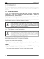
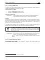
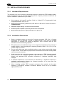
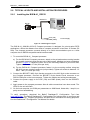
BIS M-41_ Processor Unit
Technical Description, Manual
CONTENTS
REFERENCES ..........................................................................................................vi
Conventions ............................................................................................................... vi
Reference Documentation ......................................................................................... vi
Services and Support ................................................................................................. vi
REGULATORY AND COMPLIANCE NOTICES ....................................................... vii
Power Supply ............................................................................................................ vii
GENERAL VIEW ..................................................................................................... viii
1
1.1
1.2
1.3
1.3.1
1.3.2
1.4
1.5
OVERVIEW ................................................................................................................2
Introduction .................................................................................................................2
BIS M-41_ series Features .........................................................................................2
About this Manual .......................................................................................................2
Who Should Read This Manual? .................................................................................3
HEX Notation ..............................................................................................................3
Models and Accessories .............................................................................................3
Balluff RFID Tags........................................................................................................4
2
2.1
2.1.1
2.1.2
2.1.3
2.2
2.2.1
2.2.2
2.3
2.3.1
2.3.2
2.3.3
2.3.4
2.4
2.4.1
2.4.2
2.4.3
2.4.4
2.5
2.5.1
2.5.2
2.6
2.6.1
2.6.2
2.6.3
2.6.4
INSTALLATION..........................................................................................................5
Mechanical Dimensions ..............................................................................................5
BIS M-410 (All Models) ...............................................................................................5
BIS M-410 Mounting (All Models) ................................................................................5
BIS M-411 (All Models) ...............................................................................................6
Antenna to Tag Range ................................................................................................6
BIS M-410-Series Typical Reading Ranges ................................................................7
BIS M-411-Series Typical Reading Ranges ................................................................9
Electrical Connectors ................................................................................................11
RS232 .......................................................................................................................11
RS485 .......................................................................................................................12
RS422 .......................................................................................................................13
USB ..........................................................................................................................14
Power & Wiring .........................................................................................................15
Power Requirements.................................................................................................15
Total System Current Consumption .......................................................................... 15
Cable Voltage Drop ...................................................................................................16
Current Rating for Cables .........................................................................................16
Installation Guidelines ...............................................................................................17
Hardware Requirements ...........................................................................................17
Installation Precautions .............................................................................................17
Typical Layouts and Installation Procedures ............................................................. 18
Installing the BIS M-41_ RS232 ................................................................................18
Installing the BIS M-41_ RS485 ................................................................................19
Installing the BIS M-41_ RS422 ................................................................................20
Installing the BIS M-41_ USB ....................................................................................21
3
3.1
LED INDICATORS ...................................................................................................22
Front Panel LEDs......................................................................................................22
4
4.1
CONFIGURATION METHODS .................................................................................23
Configuration Tag .....................................................................................................23
iv
4.1.1
4.2
4.2.1
4.2.2
4.3
4.4
Node ID Configuration Using Configuration Tags ...................................................... 23
Configuration Tools ...................................................................................................24
Configuration using Balluff Dashboard™ Configuration Tool ..................................... 25
Creating and Using RFID Macros with C-Macro Builder™ ........................................ 27
Command Protocols..................................................................................................29
USB Driver Installation ..............................................................................................30
5
TECHNICAL FEATURES ...........................................................................................1
v
REFERENCES
CONVENTIONS
This manual uses the following conventions:
“User” or “Operator” refers to anyone using a BIS M-41_ Processor.
“Device” refers to the BIS M-41_ Processor.
“You” refers to the System Administrator or Technical Support person using this manual to
install, mount, operate, maintain or troubleshoot a BIS M-41_ Processor.
BIS M-41_ , BIS M-62_ and BIS U-62_ RFID Processors are referred to as Processors, or
just “the Processor ”.
In addition, the terms “Subnet Node Number”, “Node ID” and “Processor ID” are used
interchangeably.
BIS M-410 correspond to the old name C-0405 unit
BIS M-411 correspond to the old name C-1007 unit
REFERENCE DOCUMENTATION
The documentation related to the BIS M-41_ Processor management is available at the
website:
www.Balluff.com
SERVICES AND SUPPORT
Balluff provides several services as well as technical support through its website. Log on to
www.balluff.com and click on the links indicated for further information including:
• PRODUCTS
Search through the links to arrive at your product page which describes specific Info,
Features, Applications, Models, Accessories, and Downloads including:
- Dashboard™: a Windows-based utility program, which allows system testing,
monitoring, and configuration using a PC. It provides Serial (RS232 or USB) and
Ethernet interface configuration.
- C-Macro Builder™: an easy to use GUI-driven utility for Windows. This software tool
allows users with minimal programming experience to “build” their own macro programs
(which are stored internally on and executed directly by RFID Processors).
vi
REGULATORY AND COMPLIANCE NOTICES
Installation and startup
Installation and startup are to be performed by trained technical personnel only. Any damage
resulting from unauthorized manipulation or improper use voids the manufacturer's
guarantee and warranty.
When connecting the processor unit to an external controller, observe proper selection and
polarity of the connection as well as the power supply (see „Installation“ on page 4).The
processor
unit
may
only
be
used
with
an
approved
power
supply
(see „Technical data“ on page 34).
Conformity
This product was developed and produced in accordance with applicable
European directives. CE conformity has been verified.
All approvals and certifications are no longer valid if:
– Components are used that are not part of the BIS Identification System,
– Components are used that have not been explicitly approved by Balluff.
Operation and testing
The operator is responsible for ensuring that local safety regulations are observed.
In the event of defects and non-correctable faults in the identification system, take the
system out of service and secure it from unauthorized use.
POWER SUPPLY
This product is intended to be installed by Qualified Personnel only.
This device is intended to be supplied by a UL Listed or CSA Certified Power Unit with
«Class 2» or LPS power source.
vii
GENERAL VIEW
BIS M-410 Models
2
3
1
4
2
Figure A
1
Comunication Interface Connector*
2
Mounting Holes
1
3
Antenna
4
LED Indicators*2
*1 = See par. 2.3
*2 = See Chapter 3
BIS M-411 Models
2
1
3
4
2
Figure B
1
Comunication Interface Connector*1
3
Antenna
2
Mounting Holes
4
LED Indicators*2
*1 = See par. 2.3
*2 = See Chapter 3
viii
1
1
OVERVIEW
BIS M-41_ TECHNICAL DESCRIPTION, USER’S GUIDE
1
1 OVERVIEW
1.1 INTRODUCTION
Welcome to the BIS M-41_ seriesRFID Processor User’s Guide. This manual will assist
you in the installation, configuration and operation of Balluff BIS M-41_ seriesRFID
Processor.
The BIS M-41_ seriesis a complete line of feature-rich, passive, high frequency, read/write
Radio-Frequency Identification devices that provide RFID data collection and control
solutions to shop floor, item-level tracking and material handling applications. BIS M-41_
seriesProcessor are designed to be compact, rugged and reliable, in order to meet and
exceed the requirements of the industrial automation industry.
1.2 BIS M-41_ SERIES FEATURES
•
Supports multiple interface connections: RS232, RS485, RS422, USB
•
Reads/Writes ISO 14443A and ISO 15693 compliant RFID tags
•
Compatible with BIS M-13_ tags from Balluff
•
Supports ABx Fast & CBx RFID command protocols
•
Operates at the internationally recognized ISM frequency of 13.56 MHz
•
Housed in rugged IP65 rated enclosure
•
LED status indicators display READY status, COM activity, RF activity, and depending on
the model, Subnet16 Node ID
•
Auto configurable and software programmable, contains flash memory for firmware
upgrades and internal configuration storage.
1.3 ABOUT THIS MANUAL
This manual provides guidelines and instructions for installing, configuring and operating
BIS M41_ Processor.
This document does NOT include explicit details regarding the BIS M-41_ Processor
commands. Specific RFID command related information such as: the process of issuing
commands from a host PC or Programmable Logic Controller (PLC) to the BIS M-41_
Processor is available in the CBx Command Protocol – User’s Guide, which is available at
www.balluff.com.
2
OVERVIEW
1
1.3.1
Who Should Read This Manual?
This manual should be read by those who will be installing, configuring and operating the
Controller. This may include the following people:
•
Hardware Installers
•
System Integrators
•
Project Managers
•
IT Personnel
•
System and Database Administrators
•
Software Application Engineers
•
Service and Maintenance Engineers
1.3.2
HEX Notation
Throughout this manual, numbers expressed in Hexadecimal notation are prefaced with “0x”.
For example, the number "10" in decimal is expressed as "0x0A" in hexadecimal.
1.4 MODELS AND ACCESSORIES
Balluff designs, manufactures and distributes a wide range of RFID equipment including
RFID Processor, network interface modules (Gateways and Hubs), RFID tags and the cables
needed to make it all work.
Listed here are the products and accessories relative to the BIS M-41_ Processor. For a
complete list of products and accessories relative to the Subnet16™ Gateway see the
Gateway User’s Guide.
To purchase any of the Balluff products listed below contact your Balluff distributor or visit
our Web site: http://www.balluff.com.
Name
Description
Order
Code
Compact processors- 4x5 cm w/Antenna RS232
Compact processors- 4x5 cm w/Antenna Subnet16™
Compact processors- 4x5 cm w/Antenna USB
Compact processors- 4x5 cm w/Antenna RS422
Compact processors- 10x7 cm w/Antenna RS232
Compact processors- 10x7 cm w/Antenna Subnet16™
Compact processors- 10x7 cm w/Antenna USB
Compact processors- 10x7 cm w/Antenna RS422
BIS00W2
BIS00W1
BIS00W4
BIS00W3
BIS00W6
BIS00W5
BIS00W8
BIS00W7
BIS M-41-Series Processor
BIS M-410-068-001-00-S115
BIS M-410-067-001-04-S92
BIS M-410-068-001-09-S72
BIS M-410-068-001-02-S115
BIS M-411-068-001-00-S115
BIS M-411-067-001-04-S92
BIS M-411-068-001-09-S72
BIS M-411-068-001-02-S115
3
BIS M-41_ TECHNICAL DESCRIPTION, USER’S GUIDE
Name
Description
1
Order
Code
Cables & Connectors
BCC M418-D279-BF-701-PS0825-020
BCC M415-M415-3A-330-PS85N6-003
BCC M415-M415-3A-330-PS85N6-010
BCC M415-M415-3A-330-PS85N6-020
BCC M415-M415-3A-330-PS85N6-050
BCC M415-M415-6A-330-PS85N6-002
BCC M415-M415-6A-330-PS85N6-010
BCC M415-M415-6A-330-PS85N6-020
BCC A315-A315-30-330-PS85N4-020
BCC A315-A315-30-330-PS85N4-050
BCC M415-0000-1A-030-PS85N6-020
BCC M415-0000-1A-030-PS85N6-050
BCC A315-0000-10-030-PS85N4-050
BCC A315-0000-10-030-PS85N6-050
BCC M414-E834-8G-672-ES64N8-050
RS232 Cable: M12, DB9-pin, PS wires
Cable: M12, 5-pin, Male/Female, ThinNet, 0.3 m
Cable: M12, 5-pin, Male/Female, ThinNet, 1 m
Cable: M12, 5-pin, Male/Female, ThinNet, 2 m
Cable: M12, 5-pin, Male/Female, ThinNet, 5 m
Cable: M12, 5-pin, Male/Male, ThinNet, 0.2 m
(Gateway to Drop-T)
Cable: M12, 5-pin, Male/Male, ThinNet, 1 m
(Gateway to Drop-T)
Cable: M12, 5-pin, Male/Male, ThinNet 2 m
(Gateway to Drop-T)
Cable: 7/8–16, 5-pin, Male/Female, ThickNet, 2 m
Cable: 7/8–16, 5-pin, Male/Female, ThickNet, 5 m
Cable: M12, 5-pin, Female / Bare Wires, ThinNet, 2 m
Cable: M12, 5-pin, Female / Bare Wires, ThinNet, 5 m
Cable: 7/8-16, 5-pin, Female / Bare Wires, 5M
Cable: M12, 5-pin, Male / Bare Wires, ThinNet, 5M
Industrial Ethernet Cable: M12, RJ45 5 m
BCC0ETJ
BCC0ERY
BCC0ERZ
BCC0ET0
BCC0ET1
BCC0ET2
BCC0ET3
BCC0ET4
BCC095A
BCC095F
BCC0ETA
BCC0ETC
BCC096Y
BCC08WT
BCC0CT1
Subnet16™ Ts, Terminators,
Connectors
BDN T-DTE-AD-01
BDN T-DTN-DD-01
BCC M435-0000-1A-000-41X575-000
BCC A315-0000-2A-R04
BCC M415-0000-2A-R04
BCC M438-0000-1A-000-51X850-000
BCC A315-0000-1A-R04
BCC M415-0000-1A-R04
BCC A335-0000-10-000-61X5A5-000
BDN T-DTE-AA-01
Drop-T Connector: 5-pin, 7/8-16 F / M12 F / 7/8-16 M
(ThickNet to ThinNet)
Drop-T Connector: M12, 5-pin, F/F/M (ThinNet to ThinNet)
Field Mountable Connector: M12, 5-pin, Female, Straight
Termination Resistor Plug: 7/8-16, 5-pin, Male, (ThickNet)
Termination Resistor Plug: M12, 5-pin, Male, (ThinNet)
RS232 Connector: M12, 8-pin, Female
Plug: Termination Resistor, M12, 5-pin, Female (ThinNet)
Plug: Termination Resistor, 7/8-16, 5-pin, Female (ThickNet)
Field Mountable Connector: 7/8-16, 5-pin, Female, Straight
T Connector: 7/8-16/5P M/F/F (ThickNet to ThickNet)
BCC07WZ
BCC07WR
BCC06ZF
BCC0A09
BCC09MR
BCC0A03
BCC0A0A
BCC0A08
BCC070F
BCC07WP
1.5 BALLUFF RFID TAGS
Balluff designs and manufactures several lines of RFID tags.
BIS M-13_ passive read/write RFID tags are especially suited for Balluff HF RFID Processor.
Tag Mounting Kits are also available.
4
INSTALLATION
2
2 INSTALLATION
2.1 MECHANICAL DIMENSIONS
2.1.1
BIS M-410 (All Models)
39.2
[1.54]
24
[0.94]
14.3
[0.56]
15.5
[0.61]
12.5
[0.49]
67
[2.64]
40
[1.57]
28
[1.10]
Ø4.5
MOUNTING HOLE 2X
[Ø.18]
Figure 1 - BIS M-410 Dimensions
2.1.2
BIS M-410 Mounting (All Models)
Figure 2 - BIS M-410 Mounting to Polycarbonate Bracket
5
mm
[in]
BIS M-41_ USER'S GUIDE
2.1.3
2
BIS M-411 (All Models)
mm
[in]
Figure 3 - BIS M-411 Dimensions
2.2 ANTENNA TO TAG RANGE
RF read/write range can be adversely affected by many environmental factors,
including electrical noise, metallic objects and liquids. The tag ranges below are
provided for design purposes only. Testing should be performed in the actual
environment for more precise range results.
Tag range values are listed in mm / inches.
Balluff Tag Model
BIS M-410
BIS M-411
Testing Environment
BIS M-132
38 / 1.49
BIS M-135
60 / 2.36
BIS M-136
70 / 2.75
Free Air
BIS M-132
25 / 0.98
Free Air
BIS M-134
45 / 1.77
Free Air
160 / 6.30
60 / 2.36
Free Air
Free Air
For further information regarding the Antenna-to-Tag Ranges, please refer to
the specific Tag’s Datasheet.
NOTE
6
INSTALLATION
2
2.2.1
BIS M-410-Series Typical Reading Ranges
Figure 4 – BIS M-410 Reading Range for Tags Type 03- Front View
Figure 5 – BIS M-410 Reading Range for Tags Type 03- Side View
7
BIS M-41_ USER'S GUIDE
2
Mifare ICCredit
Card Tag
BIS M-134
BIS M-132
Figure 6 - BIS M-410 Reading Range for Tags Type 10- Front View
Mifare ICCredit
Card Tag
BIS M-134
BIS M-132
Figure 7 - BIS M-410 Reading Range for Tags Type 10- Side View
8
INSTALLATION
2
2.2.2
BIS M-411-Series Typical Reading Ranges
Figure 8 - BIS M-411 Reading Range for BIS M-135 - Top View
Figure 9 - BIS M-411 Reading Range for BIS M-135 - Front View
9
BIS M-41_ USER'S GUIDE
2
Figure 10 - BIS M-411 Reading Range for BIS M-134 - Top View
Figure 11 - BIS M-411 Reading Range for BIS M-134 - Front View
10
INSTALLATION
2
2.3 ELECTRICAL CONNECTORS
2.3.1
RS232
The RS232 Connector (M12 8-pin, Male) is used for a point-to-point serial connection
between a host computer and the BIS M-41_ RFID compact processor.
Figure 12 - RS232 Interface M12 8-pin Male Connector
Pin
1
2
3
4
5
6
7
8
11
Name
Vdc
GND
nc
nc
nc
RX
TX
SGND
Function
Input Power
Power Ground
RS232 Receive Data
RS232 Transmit Data
Signal Ground
BIS M-41_ USER'S GUIDE
2.3.2
2
RS485
The Subnet16™ RS485 Connector (M12 5-pin, Male) is used for connecting the BIS M-41_
RFID compact processors to a Subnet16™ network.
The RFID compact processors are powered from the Subnet16™ network power.
PIN 5:
TX/RX-
PIN 4:
TX/RX+
PIN 3:
GND
PIN 1:
SIGNAL
GND
PIN 2:
VDC
Figure 13 - RS485 Subnet16™ Interface M12 5-pin Male Connector
Pin
1
2
3
4
5
Name
SGND
Vdc
GND
TX/RX+
TX/RX-
Function
Signal Ground
Subnet16™ Bus Power
Subnet16™ Bus Ground
Receive/Transmit Data positive
Receive/Transmit Data negative
12
INSTALLATION
2
2.3.3
RS422
The RS422 Connector (M12 8-pin, Male) is used for a point-to-point serial connection
between a host computer and the BIS M-41_ RFID compact processor. It offers longer
distance connections than standard RS232 and better noise protection.
Figure 14 - RS422 Interface M12 8-pin Male Connector
Pin
1
2
3
4
5
6
7
8
13
Name
Vdc
GND
TX+
TXRX+
RXnc
SGND
Function
Input Power
Power Ground
RS422 Transmit Data positive
RS422 Transmit Data negative
RS422 Receive Data positive
RS422 Receive Data negative
Signal Ground
BIS M-41_ USER'S GUIDE
2.3.4
2
USB
The BIS M-41_ USB Connector (M12 Reverse Keyed 5-pin, Male) is used for a point-to-point
serial connection between a host computer and the BIS M-41_ RFID compact processor.
PIN 5:
SHIELD
PIN 4:
GND
PIN 3:
D+
PIN 1:
V+
PIN 2:
D-
Figure 15 - USB Interface M12 Reverse Keyed 5-pin Male Connector
Pin
1
2
3
4
Name
Vdc
DD+
GND
Function
5 + Vdc USB Power Source
Data negative
Data positive
USB Power Source Ground
14
INSTALLATION
2
2.4 POWER & WIRING
The information presented below is provided to assist the installer in determining the amount
of power that will be required by the BIS M-41_ Compact processor depending on the
application.
2.4.1
Power Requirements
The BIS M-41_ Compact Processor (except USB models), requires an electrical supply
voltage of 10 to 30 Vdc. Use a regulated power supply that is capable of delivering the
requirements listed in the Technical Features.
For point-to-point or individually powered slave nodes, the calculation is straight forward. The
calculation becomes more complex for network power sources.
The following information is provided to assist you in determining the power requirements of
an RFID network application, in particular a Subnet16™ network.
NOTE
2.4.2
Power is applied directly to the Subnet16™ Network trunk and distributed
through drop cables to the Gateway and RFID compact processors. By
positioning the power supply near the middle of the network, you can limit
voltage drop at the ends, (see par. Fehler! Verweisquelle konnte nicht
gefunden werden. for network layout diagrams).
Total System Current Consumption
NOTE
The current consumption values of each product are given in the Technical
Features paragraph of the relative Installation manual and refer to the min
and max input voltage range. These values already include an adequate
safety margin. The consumption values given in the following examples have
been interpolated for an input voltage of 24 Vdc.
Max Gateway Current: 200 mA @ 12 Vdc (133 mA @ 24 Vdc).
Max Compact Processor Current: 87 mA @ 24 Vdc for BIS M-41_
Calculating Total System Current Consumption:
Total System Current Consumption = [Max Gateway Current + (Max Compact Processor
Current x Number of Compact Processors)]
Example
A Subnet16™ network powered at 24 Vdc is composed of a BIS Z-GW-001_ connecting
eight BIS M-410-067-001-04-S92 Compact Processors.
Total System Current Consumption = [0.133 A + (0.087 A X 8)] = 0.829 A
15
BIS M-41_ USER'S GUIDE
2.4.3
2
Cable Voltage Drop
In addition, each RFID compact processor on the Subnet will experience a certain amount of
voltage drop depending on the length of the cable.
Cable Resistance per Meter
•
ThinNet = 0.058 ohms per meter per wire
•
ThickNet = 0.0105 ohms per meter per wire
Calculating Voltage Drop
Voltage Drop =
(Max Compact Processor Current x Number of Compact processors) x
(Cable Resistance per Meter per Wire1 x Cable length in Meters)
Example
A Subnet16™ network is composed of a BIS Z-GW-001_ connecting eight BIS M-410-067001-04-S92 compact processors (87 mA each @ 24 Vdc). A total of 20 meters of ThinNet
cables are used to connect the devices, which have Cable Resistance = 0.058 Ohms per
meter per wire. The network power is 24 Vdc.
The voltage drop calculation must be conducted on the RFID compact processor that is
farthest from the Power Supply, as it will experience the greatest voltage drop.
NOTE
It is always recommended to power the network from the middle (Tconfiguration), to reduce total voltage drop at the ends. In the example below
this allows the fourth compact processor and not the eighth to be the furthest
from the power supply.
Voltage Drop =
[0.133 A GWY + (0.087 A x 8 compact processors)] x [(0.058 x 2) x 20
meters] = 1.92 Vdc total voltage drop for 8 compact processors
24 Vdc - 1.92/2 = 23.04 Vdc at compact processor number 4 of each
branch
2.4.4
Current Rating for Cables
The maximum current rating for the Subnet16™ network using Balluff cables and
accessories (BCCxxxx), is 4.0 A.
1
The resistance calculation must include both wires (Vdc and GND).
16
INSTALLATION
2
2.5 INSTALLATION GUIDELINES
2.5.1
Hardware Requirements
The following is a list of minimum components required to create an RFID reading system.
Other components may be required depending on the compact processor model, see the
specific installation procedure for your model.
•
Host computer with specific interface (Serial, or Subnet16™); Programmable Logic
Compact processor (PLC) or PC
•
RFID compact processor(s) BIS M-41x, BIS M-62x or BIS U-62x- Series Processors –
(RS485 models)
•
Adequate length cabling, connectors and terminators
•
Sufficient power capable of powering all the RFID components
•
Balluff RFID data carrier or labels: BIS M-1xx or BIS U-1xx
2.5.2
17
Installation Precautions
•
Select a suitable location to mount the Compact processor. BIS M-41_ Compact
processors can be mounted to wood or plastic fixtures. They may be mounted
horizontally or vertically, but should be aligned in such a manner that the LED
indicators can be seen during operation.
•
RF performance and read/write range can be negatively impacted by the proximity of
metallic objects. Avoid mounting the compact processor within 5 cm (2 in.) of any
metallic object or surface.
•
Do not route cables near other unshielded cables or near wiring carrying high voltage
or high current. Cross cables at perpendicular intersections and avoid routing cables
near motors and solenoids.
•
Avoid mounting the compact processor near sources of EMI (electro-magnetic
interference) or near devices that generate high ESD (electro-static discharge) levels.
Always use adequate ESD prevention measures to dissipate potentially high
voltages.
•
If electrical interference is encountered (as indicated by a significant reduction in
read/write performance), relocate the compact processor to an area free from
potential sources of interference.
•
When installing multiple RFID compact processors that operate at the same
frequency (13.56 MHz), maintain a minimum distance of 20 cm (8 in.) between
adjacent RF devices.
BIS M-41_ USER'S GUIDE
2
2.6 TYPICAL LAYOUTS AND INSTALLATION PROCEDURES
2.6.1
Installing the BIS M-41_ RS232
BCC0ETJ
BIS M410
Host
VDC (red)
GND (black)
Power Supply
Figure 16 - RS232 Typical Layout
The BIS M-41_-068-001-00-S115 Compact processor is designed for point-to-point RFID
applications, where the distance from host to compact processor is less than 15 meters (50
feet). The compact processor connects directly to a serial communications port on a host
computer via an RS232-compatible serial interface cable.
1. To mount the BIS M-41_ Compact processor:
a) For the BIS M-410 Compact processor, attach to the polycarbonate mounting bracket
(for metallic isolation) using the two sets of M4 screws, washers and nuts provided as
shown in Figure 2. Fasten the other end of the mounting bracket to your work area.
Tighten all screws to 0.7 Nm (6 lbs per inch).
b) For the BIS M-411 Compact processor, fasten it to the mounting surface using two
M5 (#10) screws, washers and nuts (not provided). Tighten all screws to between 1.3
and 1.7 Nm (12-15 lbs per inch).
2. Connect the BCC0ETJ M12 8-pin female connector to the M12 8-pin male connector on
the Compact processor. Connect the BCC0ETJ 9-pin female D-sub connector to an
RS232 COM port on the host computer. Tighten the cable’s two locking thumbscrews.
3. Connect the power supply to the VDC (red) and GND (black) wires on the BCC0ETJ
cable.
4. Apply power to the compact processor after all cable connections have been made. The
LEDs on the unit will flash.
5. On the host computer, set COM port parameters to: 9600 baud, 8 data bits, 1 stop bit, no
parity and no handshaking.
To verify operations, download the Balluff Dashboard™ Configuration Tool from
www.balluff.com. The Balluff Dashboard™ Configuration Tool allows users to configure and
control their BIS M-41_ compact processors and send RFID commands for testing purposes.
See the Dashboard™ Configuration Tool Manual for details.
18
INSTALLATION
2
Installing the BIS M-41_ RS485
BCC07WR
BCC0ET0
BCC07WR
BCC0ETJ
BCC09MR
BCC0ET0
BCC0ET4
BCC0ET0
BCC09MR
BCC0ET0
BCC07WR
BCC0ET0
BCC07WR
BCC0ET0
2.6.2
BIS M-410
BIS M-411
BIS M-411
Gateway
VDC GND
to Power Supply
to Host
to
Configuration PC
Figure 17 - RS485 Typical Layouts
The BIS M-41_-067-001-04-S92 Compact processor is designed for Subnet16™ RFID
applications, where the compact processor is connected in an RS485 network via
Subnet16™-compatible cables to the host through a Gateway or Hub.
1. To mount the BIS M-41_ Compact processor:
a) For the BIS M-410 Compact processor, attach to the polycarbonate mounting bracket
(for metallic isolation) using the two sets of M4 screws, washers and nuts provided as
shown in Figure 2. Fasten the other end of the mounting bracket to your work area.
Tighten all screws to 0.7 Nm (6 lbs per inch).
b) For the BIS M-411 Compact processor, fasten it to the mounting surface using two
M5 (#10) screws, washers and nuts (not provided). Tighten all screws to between 1.3
and 1.7 Nm (12-15 lbs per inch).
2. Attach a Subnet16™ compatible cable (i.e. BCC0ET0) to the M12 5-pin male Subnet16™
connector on the compact processor. Connect the other end of this cable to your
Subnet16™ network.
3. To complete the Subnet16™ network installation, including power supply wiring, trunk
wiring, network termination, Gateway/Hub wiring, and for a complete list of compatible
accessory cables and Subnet16™ network layout examples, see the Subnet16™
Gateway or Subnet16™ Hub Manuals.
After installation, the Subnet16™ network can be configured through the Subnet16™
Gateway/Hub using the Balluff Dashboard™ Configuration Tool. See the Dashboard™
Configuration Tool Manual for details.
19
BIS M-41_ USER'S GUIDE
2.6.3
2
Installing the BIS M-41_ RS422
BCC0A03
Host
BIS M-410
Power Supply
Figure 18 - RS422 Typical Layout
The BIS M-41_-068-001-02-S115 Compact processor is designed for point-to-point RFID
applications, where the distance from host to compact processor can be up to 1200 meters
(3940 feet), depending on the baud rate used. It therefore supports longer distances than
those acceptable for RS232 communications and it is also suggested in electrically noisy
environments. The compact processor connects directly to an RS422 serial communications
port on a host computer (or PLC) via an RS422-compatible cable. Ensure that an RS422
port is installed on the host or that an RS232/RS422 converter is connected to an
RS232 COM port on the host.
1. To mount the BIS M-41_ Compact processor:
a) For the BIS M-410 Compact processor, attach to the polycarbonate mounting bracket
(for metallic isolation) using the two sets of M4 screws, washers and nuts provided as
shown in Figure 2. Fasten the other end of the mounting bracket to your work area.
Tighten all screws to 0.7 Nm (6 lbs per inch).
b) For the BIS M-411 Compact processor, fasten it to the mounting surface using two
M5 (#10) screws, washers and nuts (not provided). Tighten all screws to between 1.3
and 1.7 Nm (12-15 lbs per inch).
2. Build an RS422 compatible cable using the BCC0A03 M12 8-pin female connector. Use
suitable shielded twisted-pair wires for RS422 connection and power supply signals
according to the connector pinout (see Figure 14). Connect the BCC0A03 M12 8-pin
female connector to the M12 8-pin male connector on the Compact processor. Connect
the other end of the cable (wires or user-supplied connectors) to the host (PLC) and
power supply.
3. Apply power to the compact processor after all cable connections have been made. The
LEDs on the unit will flash.
4. On the host computer, set COM port parameters to: 9600 baud, 8 data bits, 1 stop bit, no
parity and no handshaking.
To verify operations, download the Balluff Dashboard™ Configuration Tool from
www.balluff.com. The Balluff Dashboard™ Configuration Tool allows users to configure and
control their BIS M-41_ compact processors and send RFID commands for testing purposes.
See the Dashboard™ Configuration Tool Manual for details.
NOTE
If the host does not support the Windows environment, configuration must be
made by sending the configuration command protocol strings, refer to the
ABx Fast Command Protocol Manual.
20
INSTALLATION
2
2.6.4
Installing the BIS M-41_ USB
BCC0ETF
Host
BIS M-410
Figure 19 - USB Typical Layout
The BIS M-41_--68-001-09-S72 Compact processor is designed for point-to-point RFID
applications, where the distance from host to compact processor is less than 15 meters (50
feet). The compact processor connects directly to a serial communications port on a host
computer via a USB-compatible interface cable.
1. To mount the BIS M-41_ Compact processor:
a) For the BIS M-410 Compact processor, attach to the polycarbonate mounting bracket
(for metallic isolation) using the two sets of M4 screws, washers and nuts provided as
shown in Figure 2. Fasten the other end of the mounting bracket to your work area.
Tighten all screws to 0.7 Nm (6 lbs per inch).
b) For the BIS M-411 Compact processor, fasten it to the mounting surface using two
M5 (#10) screws, washers and nuts (not provided). Tighten all screws to between 1.3
and 1.7 Nm (12-15 lbs per inch).
2. Download the „Bis4D_com“ USB driver archive from www.balluff.com and extract the
archive to a separate folder on the host computer.
3. Connect the BCC0ETF M12 reverse keyed 5-pin female connector to the M12 reverse
keyed 5-pin male connector on the product.
4. Connect the BCC0ETF USB Type A connector to a USB COM port on the host computer.
The LEDs on the compact processor will flash. At this point, Windows will detect the new
hardware device and request the location of the „Bis4D_com“ USB driver files.
5. Browse to the folder containing the „Bis4D_com“ USB driver files. Refer to the
instructions included with the „Bis4D_com“ USB driver download or to par. 4.4, to
complete the installation of the „Bis4D_com“ USB driver.
To verify operations, download the Balluff Dashboard™ Configuration Tool from
www.balluff.com. The Balluff Dashboard™ Configuration Tool allows users to configure and
control their BIS M-41_ compact processors and send RFID commands for testing purposes.
See the Dashboard™ Configuration Tool Manual for details.
21
BIS M-41_ USER'S GUIDE
3
3 LED INDICATORS
3.1 FRONT PANEL LEDS
LED Name
LED Color
LED Description
POWER
GREEN
The READY LED is ON whenever power
is applied to the Balluff.
RF
RED
The RF LED illuminates when RF power
is being transmitted by the antenna.
COM
GREEN
The COM (communications) LED flashes
ON and OFF when data is being
transmitted between the antenna and a
tag.
When in Continuous Read mode, the
COM LED will remain ON and will turn
OFF briefly only while data is being read
from or written to a tag.
RS232
AMBER
This LED indicates the RS232 model.
RS485
AMBER
The five Node ID LEDs indicate (in Binary,
from right to left) the current Node ID
value assigned to the compact processor.
RS422
AMBER
This LED indicates the RS422 model.
USB
AMBER
This LED indicates the USB model.
Table 1 - Front Panel LEDs
22
CONFIGURATION METHODS
4
4 CONFIGURATION METHODS
There are several configuration methods available for your compact processor depending on
the interface type and application:
•
Configuration Tag
•
Configuration Tools: Balluff Dashboard™and C-Macro Builder™
•
Command Protocol
4.1 CONFIGURATION TAG
A configuration tag is included with your BIS M-41_ compact processor. This can be used to
reset all BIS M-41_ compact processors to their factory default configuration settings.
For Subnet16™ models (BIS M-41_ RS485 models), this tag can also be used to set the
Node ID of each compact processor in the network.
Figure 20 - BIS M-41_ Configuration Tag
4.1.1
Node ID Configuration Using Configuration Tags
Only BIS M-41_-067-001-04-S92 compact processors can be connected to a Gateway’s
Subnet network and each must be assigned a unique Node ID value between 1 and 16.
When an RFID compact processor is connected to the Gateway’s Subnet network, the
Gateway will query the new compact processor to obtain certain configuration values
(specifically the Node ID number). If the Gateway does not detect a Node ID conflict, it will
“allow” the RFID compact processor onto the Subnet network.
By using the BIS M Series Configuration Tag that is included with each RS485-based
Balluff BIS M-41_ RFID Compact processor, the Node ID value can be dynamically assigned
by the Gateway or can be manually assigned by the user.
For the Gateway to dynamically assign a Node ID value to a compact processor, the
compact processor must first be initialized with the Node ID value of zero. This is the
equivalent of having no Node ID assigned.
23
BIS M-41_ USER'S GUIDE
4
All Balluff RS485-based compact processors ship with their Node ID value
set to 0.
NOTE
When a powered compact processor (that is set to Node ID 0) is connected to the Subnet, it
will not initially be recognized by the Gateway until the Configuration Tag is placed in the
antenna’s RF field. After a few seconds the compact processor will display its new assigned
Node ID value in binary code from right to left using the five amber Node LEDs on the
compact processor, see Table 1.
When dynamically assigning a Node ID value for a new compact processor, the Gateway will
either assign the next available Node ID value or the value that the Gateway recognizes as
offline or “missing” – that is, a Node ID value that previously existed, but has since
disappeared from the network.
Because the Gateway stores a backup of each Subnet Node’s configuration, should an RFID
compact processor ever fail, a replacement compact processor can be installed quickly and
easily. The new compact processor will be automatically assigned the same Node ID value
and configuration as the replaced compact processor, provided the Configuration Tag is
introduced to the antenna field after startup and then removed.
Avoid that the configuration tag is simultaneously read by more than one
compact processor.
NOTE
4.2 CONFIGURATION TOOLS
Balluff offers the following powerful RFID configuration utilities for Microsoft Windows 2000,
XP, Vista and 7 systems:
•
Balluff Dashboard™ Configuration Tool
•
C-Macro Builder™
These configuration tools can be downloaded from the Balluff website: www.balluff.com
24
CONFIGURATION METHODS
4
4.2.1
Configuration using Balluff Dashboard™ Configuration Tool
The Balluff Dashboard™ Configuration Tool is a software application that allows users to
view, modify, save and update the configuration settings of their Balluff compact processors.
Follow the instructions below to operate the Balluff Dashboard Configuration Tool and to set
the Balluff device’s configuration.
1. Install the Compact processor as described in the relevant sub-paragraph in 2.6.
2. For USB models, install the Balluff USB driver to your PC as described in par. 4.4.
3. Connect the Compact processor to your PC, power up and wait for the boot
procedure to finish.
4. Run the Balluff Dashboard™ Configuration Tool.
5. From the Connection screen, choose your compact processor from the list.
Figure 21 - Balluff Dashboard™RS232 Compact Processorselection
6. Choose the appropriate COM port and Baudrate; then click “Connect”.
25
BIS M-41_ USER'S GUIDE
4
Figure 22 - Balluff Dashboard™COM and Baudrate Selection
The Dashboard should send some commands to retrieve device and configuration
information from the device. If serial communications are set up correctly, the device
configuration area within the Balluff Dashboard should now look like this:
Figure 23 - Balluff Dashboard™RS232 Compact processor Configuration
See the Balluff Dashboard™ User's Manual for more configuration details.
26
CONFIGURATION METHODS
4
4.2.2
Creating and Using RFID Macros with C-Macro Builder™
What are RFID Command Macros?
RFID Command Macros are a powerful feature of Balluff Balluff Compact processors.
Macros are simple programs that direct a compact processor to execute multiple preprogrammed instructions.
Because macros reside within the compact processor’s internal memory, they can be
programmed to instruct the compact processor to automatically read and/or write a specified
set of data to an RFID tag without the compact processor ever having to receive a command
from the host. In fact, the compact processors do not even require a connection to a host in
order to execute macros.
Each macro can contain up to 255 bytes of data and each supported compact processor can
store up to eight macros at a time. Though they are stored locally on the compact processor,
macros are also backed up in the Gateway’s flash memory as well.
Why use macros?
The power of macros is in distributed intelligence, the reduction in network bus traffic and the
ability to accelerate routine decision making at the point of data collection.
What can macros do?
In addition to the automated reading and writing of data, macro capabilities include:
•
The ability to write time stamps to RFID tags
•
The ability to filter command responses to only those of interest to the host (such as
when an error occurs or when a tag has arrived in the RF field)
•
The ability to harness powerful logic and triggering capabilities such as; read, write,
start/stop continuous read, data compare, branch, transmit custom string, and set
outputs.
What is a macro trigger?
Macros are initiated by “triggers.” Triggers can be configured in numerous ways. A simple
command from the host, such as “execute macro number three” can be considered a trigger.
Triggers can be configured, for example, to activate a macro when a tag enters or leaves a
compact processor’s RF field.
Balluff RFID compact processors can store up to eight separate triggers in addition to the
eight macros they can also house. Any trigger can activate any of the eight stored macros.
How are macros created?
Macros are created using the powerful, yet simple, C-Macro Builder™ Configuration Tool
from Balluff. The easy to use GUI allows the user to create powerful RFID macro programs
quickly and easily.
27
BIS M-41_ USER'S GUIDE
4
When used with Balluff Dashboard™ Configuration Tool , users can effortlessly download,
erase, and manage their macros and triggers, as well as set the operational configurations of
their RFID compact processors and Subnet16™ Gateways.
Which communication interfaces support the use of macros?
Macros are supported on the following Balluff Compact processors: Ethernet, Profibus,
DeviceNet, RS232 and USB interfaces.
What happens to existing Macros if a compact processor must be
replaced?
When using a Subnet16™ Gateway, users do not need to worry. Macros and triggers
normally residing in an RFID compact processor’s flash memory are always backed up in the
Gateway’s flash memory as well. Therefore, if a compact Processorshould ever require
replacement, all existing macro and trigger settings are automatically exported from the
Gateway to the new RFID compact processor.
In short, when an RFID compact processor is initially connected to the Gateway, macro and
trigger data from the compact processor’s flash memory is compared to the macro and
trigger data backed up in the Gateway from the previous RFID compact processor. If the
data does not match that which is stored on the Gateway, the compact processor’s flash
memory will be overwritten with the backed up data stored in the Gateway’s flash memory.
How can I learn more about the Dashboard and C-Macro Builder?
More information regarding macros, triggers, uploading, downloading, configuring and
monitoring Balluff RFID equipment is available in the respective User’s Manuals for these
products, which are available on the Balluff website at:
www.balluff.com
28
CONFIGURATION METHODS
4
C-Macro Builder™ is an easy to use GUI-driven Configuration Tool for Windows that allows
users to create powerful RFID command macro programs.
Figure 24 - C-Macro Builder™
NOTE
For specific information regarding the configuration and use of either of
these utilities, please see the accompanying documentation included when
downloading each software application.
4.3 COMMAND PROTOCOLS
BIS M-41_ compact processors can be directly programmed using a proprietary command
protocol over the specific host interface. This is useful for compact processors connected to
a PLC over a Serial network (i.e. RS422, etc.).
All BIS M-41_ compact processors use the ABx Fast Command Protocol, except for
RS485 Subnet16™ models.
NOTE
All BIS M-41_-067-001-04-S92 compact processors are used in conjunction
with Subnet16™ Gateway and Subnet16™ Hub interface modules, which all
use the CBx Command Protocol.
Refer to the specific Command Protocol Technical Description, User’s Guide for details.
29
BIS M-41_ USER'S GUIDE
4
4.4 USB DRIVER INSTALLATION
This paragraph contains instructions for installing the Windows 2000/XP USB driver for
Balluff RFID devices. Complete the following steps before installing the RFID USB driver.
1.
Download the RFID USB driver package from www.balluff.com.
2.
Extract the driver files to a separate folder on your host computers’ Desktop.
3.
Connect the USB interface cable (and power supply, if applicable) as described in par.
2.6.4.
4.
Apply power to your RFID device. Windows should detect the new hardware and start
the Found New Hardware Wizard. If it does not, run the Add Hardware applet in
Windows’ Control Panel.
Figure 25 - Found New Hardware Wizard – Do Not Connect to Windows Update
Figure 26 - Found New Hardware Wizard – Install From List
5.
Select “Install from a list or specific location” and then click Next.
30
4
6.
CONFIGURATION METHODS
Check the box labeled: “Include this location in the search” and then click the Browse
button.
Figure 27 - Found New Hardware Wizard – Include this Location
7.
Browse to the folder containing the extracted RFID USB driver files and then click OK.
Figure 28 - Found New Hardware Wizard - Browse for Folder
31
BIS M-41_ USER'S GUIDE
8.
4
Click Next to install the USB driver.
Figure 29 - Found New Hardware Wizard – Ready to Install
Please wait while the Found New Hardware Wizard installs the USB driver.
Figure 30 - Installing the USB Driver
32
CONFIGURATION METHODS
4
9.
After the USB driver has been installed, click Finish.
Figure 31 - USB Driver Installation Complete
NOTE
Immediately after you click Finish, the Found New Hardware Wizard will
close and then automatically restart, prompting you to repeat the USB driver
installation. This occurs because Windows requires a second trip through
the installation routine to install and configure a virtual COM port for use by
the RFID USB device.
10. Repeat Steps 5-9 to install the virtual COM port and complete the installation of the
RFID USB driver.
Figure 32 - Virtual COM Port USB Driver Installation Complete
33
5 TECHNICAL FEATURES
ELECTRICAL FEATURES
Supply Voltage:
RS232, RS485, RS422
USB
DC Input Current max.
RS232, RS485, RS422
USB
Communication Interfaces:
RS232
RS485
RS422
USB
RADIO FEATURES
Frequency
Air Protocols
ENVIRONMENTAL FEATURES
Operating Temperature
Storage Temperature
Humidity max.
Vibration Resistance
EN 60068-2-6
Vibration Resistance
EN 60068-2-6
Protection Class
EN 60529
PHYSICAL FEATURES
Dimensions
Weight
USER INTERFACE
LED Indicators
10 to 30 Vdc
5 VDC
BIS M-410
150 to 60 mA
BIS M-411
400 to 140 mA
500 mA
RS232
RS485
RS422
USB 2.0
13.56 MHz
ISO 14443A, ISO 15693
-20° to 50 °C (-4 to 122 °F)
-20° to 70 °C (-4 to 158 °F)
90% non condensing
14 mm @ 2 to 10 Hz;
1.5 mm @ 13 to 55 Hz;
2 g @ 70 to 200 Hz;
2 hours on each axis
30 g; 11 ms;
3 shocks on each axis
IP67
BIS M-410
67 x 40 x 24 mm
(2.64 x 1.57 x .94 in)
47 g (1.7 oz)
BIS M-411
116.4 x 75.2 x 24 mm
(4.58 x 2.96 x .94 in)
210 g (7.4 oz)
RF, COM, Operating Mode, Power
The features given are typical at a 25 °C ambient temperature (if not otherwise indicated).
1
1
Nr. 896 711 E . Edition 1305; Subject to modification.