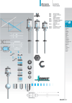
1
BIS M-62_ Processor Unit
Technical Description, Manual
CONTENTS
REFERENCES ...........................................................................................................1
Conventions ................................................................................................................1
Reference Documentation ..........................................................................................1
Services and Support ..................................................................................................1
REGULATORY AND COMPLIANCE NOTICES .........................................................2
Power Supply ..............................................................................................................2
GENERAL VIEW .........................................................................................................3
1
1.1
1.2
1.3
1.3.1
1.3.2
1.4
1.5
OVERVIEW ..............................................................................................................11
Introduction ...............................................................................................................11
HF-Series Features ...................................................................................................11
About this Manual .....................................................................................................11
Who Should Read This Manual? ...............................................................................12
HEX Notation ............................................................................................................12
Models and Accessories ...........................................................................................12
Balluff RFID Tags.....................................................................................................13
2
2.1
2.1.1
2.1.2
2.1.3
2.1.4
2.1.5
2.1.6
2.2
2.2.1
2.2.2
2.2.3
2.2.4
2.3
2.3.1
2.3.2
2.3.3
2.3.4
2.3.5
2.3.6
2.3.7
2.4
2.4.1
2.4.2
2.4.3
2.4.4
2.5
2.5.1
2.5.2
2.6
2.6.1
2.6.2
INSTALLATION........................................................................................................15
Mechanical Dimensions ............................................................................................15
BIS M-620-068-A01-00-_ _ Serial RS232 Models ..................................................... 15
BIS M-620-067-A01-04-_ _ Subnet16 Models .......................................................... 16
BIS M-626-_ _ Ethernet/IP Models ............................................................................ 17
BIS M-623-_ _ DeviceNet Models ............................................................................. 18
BIS M-622-_ _ Profibus Models ................................................................................19
BIS M-628-_ _ PROFINET Models............................................................................ 20
BIS M-37_ Antenna Mounting ..................................................................................25
Direct Antenna Mounting ...........................................................................................25
Remote Antenna Mounting .......................................................................................26
Minimum Mounting Distance Between Adjacent Antennas ........................................ 27
Antenna to Tag Range ..............................................................................................28
Electrical Connectors ................................................................................................29
RS232 .......................................................................................................................29
RS485 .......................................................................................................................30
Industrial Ethernet IP.................................................................................................31
DeviceNet .................................................................................................................32
Profibus.....................................................................................................................34
Profinet .....................................................................................................................36
Digital I/O (-12 models) .............................................................................................38
Power & Wiring .........................................................................................................39
Power Requirements.................................................................................................39
Total System Current Consumption .......................................................................... 39
Cable Voltage Drop ...................................................................................................40
Current Rating for Cables .........................................................................................40
Installation Guidelines ...............................................................................................41
Hardware Requirements ...........................................................................................41
Installation Precautions .............................................................................................41
Typical Layouts and Installation Procedures ............................................................. 42
Installing the BIS M-620-068-A01-00-S_ RS232 ....................................................... 42
Installing the BIS M-620-067-A1-04-S_ RS485 ......................................................... 43
i
2.6.3
2.6.4
2.6.5
2.6.6
2.7
2.7.1
2.7.2
2.7.3
Installing the BIS M-626-069-A01-06_ Industrial Ethernet (IND) ............................... 44
Installing the BIS M-623-071-A01-03-S_ DeviceNet (DNT) ....................................... 45
Installing the BIS M-622-070-A01-03-ST33 Profibus (PBS) ...................................... 46
Installing the BIS M-628-075-A01-03-ST34 PROFINET (PNT).................................. 48
Digital I/O (-12 models) .............................................................................................50
Input..........................................................................................................................50
Outputs .....................................................................................................................52
Digital I/O Command Control ....................................................................................56
3
3.1
3.1.1
3.1.2
3.1.3
3.1.4
3.1.5
3.1.6
LED INDICATORS ...................................................................................................57
Front Panel LEDs......................................................................................................57
BIS M-620-068-A01-00_ RS232 Models ................................................................... 57
BIS M-620-067-A01-04_ RS485 Models ................................................................... 57
BIS M-626-069-A01-06_ INDUSTRIAL Models ......................................................... 58
BIS M-623-071-A01-03-ST30 DEVICENET Models .................................................. 58
BIS M-622-070-A01-03-ST33 PROFIBUS Models .................................................... 59
BIS M-628-075-A01-03-ST34 PROFINET Models .................................................... 60
4
4.1
4.1.1
4.2
4.2.1
4.2.2
4.2.3
4.3
CONFIGURATION METHODS .................................................................................61
Configuration Tag .....................................................................................................61
Node ID Configuration Using Configuration Tags ...................................................... 61
Configuration Tools ...................................................................................................62
Configuration Using Balluff Dashboard™ .................................................................. 63
Software Upgrades Using Balluff Dashboard™ ......................................................... 65
Creating and Using RFID Macros with C-Macro Builder™ ........................................ 65
Command Protocols..................................................................................................69
5
5.1
5.2
5.3
5.4
5.5
5.6
5.7
5.8
5.8.1
5.8.2
5.9
5.9.1
5.9.2
ETHERNET/IP INTERFACE .....................................................................................71
Ethernet/IP Configuration Overview .......................................................................... 72
HTTP Server & OnDemand PLC Support ................................................................. 72
HTTP Server and OnDemand Utilities ....................................................................... 73
IP Configuration via HTTP Server ............................................................................. 74
OnDemand Configuration for Ethernet/IP .................................................................. 76
Configuring PLC Controller Tags .............................................................................. 79
Checking OnDemand Status .....................................................................................81
Verifying Data Exchange with RSLogix 5000 ............................................................ 82
Ethernet/IP Handshaking ..........................................................................................82
Ethernet/IP Handshaking Example............................................................................ 83
Ethernet/IP: Object Model .........................................................................................84
Ethernet/IP Required Objects....................................................................................85
EtherNet/IP: Vendor Specific Objects........................................................................ 89
BIS M-626 Consume Data Object (0x64 - 32 Instances) ........................................... 89
5.9.3 Application Object (0x67 – 10 Instances).................................................................... 92
6
6.1
6.2
6.2.1
6.2.2
6.2.3
6.3
6.3.1
6.3.2
MODBUS TCP INTERFACE.....................................................................................95
Modbus TCP Overview .............................................................................................95
Modbus TCP Configuration via HTTP Server ............................................................ 95
Modbus TCP - Command Packet Structure .............................................................. 98
Modbus TCP - Response Packet Structure ............................................................... 98
Modbus TCP - Mapping for Node 33 ......................................................................... 99
Modbus TCP - Handshaking ................................................................................... 100
Modbus TCP - Host/BIS M-626_ Handshaking ....................................................... 101
Modbus TCP - Handshaking Example .................................................................... 101
7
STANDARD TCP/IP INTERFACE .......................................................................... 103
ii
7.1
7.2
7.3
7.3.1
7.3.2
Standard TCP/IP Overview ..................................................................................... 103
Standard TCP/IP - IP Configuration via HTTP Server ............................................. 103
Standard TCP/IP - Command & Response Examples ............................................. 106
Standard TCP/IP - Command Structure Example ................................................... 107
Standard TCP/IP - Response Structure Example .................................................... 107
8
8.1
8.2
8.2.1
8.2.2
8.2.3
8.2.4
8.2.5
DEVICENET INTERFACE ...................................................................................... 108
DeviceNet Overview................................................................................................ 108
DeviceNet Configuration ......................................................................................... 108
Importing the Controller.EDS File ............................................................................ 108
Configuring Controller and PLC DeviceNet Communications .................................. 109
Configuring Data Rate and Node Address .............................................................. 114
DeviceNet - Exchanging Data and Handshaking ..................................................... 115
DeviceNet - Handshaking Example ......................................................................... 116
9
9.1
9.2
9.3
9.4
9.4.1
9.4.2
9.4.3
9.4.4
9.4.5
9.5
9.5.1
9.5.2
9.5.3
9.5.4
9.5.5
PROFIBUS INTERFACE ........................................................................................ 119
Profibus Overview ................................................................................................... 119
Profibus-DP ............................................................................................................ 119
Data Exchange ....................................................................................................... 120
Protocol Implementation ......................................................................................... 121
Definitions ............................................................................................................... 121
Control Field ........................................................................................................... 122
SAP Field ................................................................................................................125
Length Field ............................................................................................................ 125
Application Data Buffer ........................................................................................... 126
Examples of Profibus Command/Response Mechanism ......................................... 126
Example 1: Normal Command/Response Sequence .............................................. 128
Example 2: Unsolicited Responses (Continuous Read Mode) ................................. 138
Example 3: Fragmentation of Responses................................................................ 142
Example 4: Fragmentation of Commands ............................................................... 151
Example 5: Resynchronization ................................................................................ 162
10
10.1
10.2
10.3
10.4
10.4.1
10.4.2
10.4.3
10.4.4
10.4.5
10.5
PROFINET INTERFACE ........................................................................................ 167
Profinet Overview .................................................................................................... 167
Profinet IO............................................................................................................... 167
Data Exchange ....................................................................................................... 168
Protocol Implementation ......................................................................................... 169
Definitions ............................................................................................................... 169
Control Field ...........................................................................................................170
SAP Field ................................................................................................................173
Length Field ............................................................................................................ 173
Application Data Buffer ........................................................................................... 174
Examples of Profnet Command/Response Mechanism........................................... 174
11
11.1
11.2
TECHNICAL FEATURES ....................................................................................... 178
BIS M-62_ Processor units...................................................................................... 178
BIS M-37_ Antennas ............................................................................................... 179
iii
REFERENCES
CONVENTIONS
This manual uses the following conventions:
“User” or “Operator” refers to anyone using a BIS M-62_ Processor.
“Device” refers to the BIS M-62_ Processor.
“You” refers to the System Administrator or Technical Support person using this manual to
install, mount, operate, maintain or troubleshoot a BIS M-62_ Processor.
BIS M-41_ , BIS M-62_ and BIS U-62_ RFID Processors are referred to as Processors, or
just “the Processor ”.
In addition, the terms “Subnet Node Number”, “Node ID” and “Processor ID” are used
interchangeably.
BIS M-620-068_ correspond to the old name HF-CNTL-232_ unit
BIS M-620-067_ correspond to the old name HF-CNTL-485_ unit
BIS M-622-068_ correspond to the old name HF-CNTL-PBS_ unit
BIS M-623-071_ correspond to the old name HF-CNTL-DNT_ unit
BIS M-626-069_ correspond to the old name HF-CNTL-IND_ unit
BIS M-628-075_ correspond to the old name HF-CNTL-PNT_ unit
REFERENCE DOCUMENTATION
The documentation related to the BIS M-62_ Processor Unit management is available on the
specific product page at the website:
www.balluff.com
SERVICES AND SUPPORT
Balluff provides several services as well as technical support through its website. Log on to
www.balluff.com and click on the links indicated for further information including:
• PRODUCTS
Search through the links to arrive at your product page which describes specific Info,
Features, Applications, Models, Accessories, and Downloads including:
- Dashboard™: a Windows-based utility program, which allows system testing,
monitoring, and configuration using a PC. It provides Serial (RS232 or USB) and
Ethernet interface configuration.
- C-Macro Builder™: an easy to use GUI-driven utility for Windows. This software tool
allows users with minimal programming experience to “build” their own macro programs
(which are stored internally on and executed directly by RFID Processors).
1
REGULATORY AND COMPLIANCE NOTICES
This product is intended to be installed by Qualified Personnel only.
This product must not be used in explosive environments.
Only connect Ethernet and data port connections to a network which has routing only within
the plant or building and no routing outside the plant or building.
POWER SUPPLY
This product is intended to be installed by Qualified Personnel only.
This device is intended to be supplied by a UL Listed or CSA Certified Power Unit with
«Class 2» or LPS power source.
2
GENERAL VIEW
RS232 Models
1
5
2
3
4
6
5
Figure A
1
HF Antenna Connector
4
COM LED
2
Ready LED
5
Mounting Bracket
3
RF LED
6
Host (RS232) and Power Connector
3
RS485 Models
1
7
5
2
3
4
6
5
Figure B
4
1
HF Antenna Connector
4
COM LED
2
Ready LED
5
Mounting Bracket
3
RF LED
6
Host (RS485) and Power Connector
7
Node ID LEDs
IND Models
1
8
5
2
3
7
4
6
5
Figure C
1
HF Antenna Connector
5
Mounting Bracket
2
Ready LED
6
Power Connector
3
RF LED
7
Host (Ethernet) Connector
4
COM LED
8
IP Address Status LEDs
5
DNT Models
1
8
5
2
3
7
4
6
5
Figure D
6
1
HF Antenna Connector
5
Mounting Bracket
2
Ready LED
6
RS232 Configuration Connector
3
RF LED
7
Host (DeviceNet) and Power Connector
4
COM LED
8
DeviceNet Status LED
PBS Models
1
10
5
2
9
3
8
4
7
6
5
Figure E
1
HF Antenna Connector
6
RS232 Configuration Connector
2
Ready LED
7
Power Connector
3
RF LED
8
Host (Profibus Out) Connector
4
COM LED
9
Host (Profibus In) Connector
5
Mounting Bracket
10 Profibus Status LEDs
7
PNT Models
1
10
5
2
9
3
8
4
7
6
5
Figure F
8
1
HF Antenna Connector
6
RS232 Configuration Connector
2
Ready LED
7
Power Connector
3
RF LED
8
Profinet 2 Connector
4
COM LED
9
Profinet 1 Connector
5
Mounting Bracket
10 Profinet Status LEDs
BIS M-371-000-A01
BIS M-372-000-A01
BIS M-373-000-A01
BIS M-370-000-A02
Figure G
9
10
OVERVIEW
1
1 OVERVIEW
1.1 INTRODUCTION
Welcome to the BIS M-62_ Processor Manual. This manual will assist you in the
installation, configuration and operation of the BIS M-62_ family of processor units.
The BIS M-62_ is a complete line of feature-rich, passive, high frequency, read/write RadioFrequency Identification devices that provide RFID data collection and control solutions to
shop floor, item-level tracking and material handling applications. BIS M-62_ processor units
are designed to be compact, rugged and reliable, in order to meet and exceed the
requirements of the industrial industry. For an overview of RFID operating principles and tags
see Appendix Fehler! Verweisquelle konnte nicht gefunden werden..
1.2 HF-SERIES FEATURES
•
High performance, industrial, multi-protocol RFID processor units
•
Available support for multiple communication protocols: Subnet16™, standard TCP/IP,
Ethernet/IP, MODBUS TCP, Profibus-DP-V1 and Profinet IO
•
Supports multiple interface connections: RS232, RS485, Ethernet, DeviceNet, Profibus;
Profinet
•
Reads/Writes ISO 14443A and ISO 15693 compliant RFID tags
•
Compatible with BIS m-1xx Series RFID tags from Balluff
•
Supports Balluff's ABx Fast & CBx RFID command protocols
•
Operates at the internationally recognized ISM frequency of 13.56 MHz
•
Housed in rugged IP65 rated enclosure
•
LED status indicators display READY status, COM activity, RF activity, and depending on
the model, Subnet16 Node ID, DeviceNet, Profibus or Profinet network status
•
Auto configurable and software programmable, contains flash memory for firmware
upgrades and internal configuration storage.
1.3 ABOUT THIS MANUAL
This manual provides guidelines and instructions for installing, configuring and operating HFSeries Processor units.
This document does NOT include explicit details regarding the HF-Series Processor units
commands. Specific RFID command related information such as: the process of issuing
commands from a host PC or Programmable Logic Processor units (PLC) to the HF-Series
Processor units is available in the CBx Command Protocol – Processor manual , which is
available at www.balluff.com.
11
BIS M-62_ MANUAL
1
1.3.1
Who Should Read This Manual?
This manual should be read by those who will be installing, configuring and operating the
Processor units. This may include the following people:
•
Hardware Installers
•
System Integrators
•
Project Managers
•
IT Personnel
•
System and Database Administrators
•
Software Application Engineers
•
Service and Maintenance Engineers
1.3.2
HEX Notation
Throughout this manual, numbers expressed in Hexadecimal notation are prefaced with “0x”.
For example, the number "10" in decimal is expressed as "0x0A" in hexadecimal.
1.4 MODELS AND ACCESSORIES
Balluff designs, manufactures and distributes a wide range of RFID equipment including
Processor units, network interface modules (Gateways and Hubs), RFID tags and the cables
needed to make it all work.
Listed here are the products and accessories relative to the HF-Series processor units. For a
complete list of products and accessories relative to the Subnet16™ Gateway see the
Gateway Processor manual.
To purchase any of the Balluff products listed below contact your Balluff distributor or visit
our Web site: http://www.balluff.com.
Name
Description
Order
Code
BIS M-62_ Processor units
BIS M-620-068-A01-00-S115
BIS M-620-068-A01-00-ST29
BIS M-620-067-A01-04-S92
BIS M-620-067-A01-04-ST30
BIS M-626-069-A01-06-ST31
BIS M-626-069-A01-06-ST32
BIS M-623-071-A01-03-ST30
BIS M-622-070-A01-03-ST33
BIS M-628-075-A01-03-ST34
BIS M-62_ Processor units - RS232
BIS M-62_ Processor units - RS232 w I/O
BIS M-62_ Processor units - RS485 Subnet16™
BIS M-62_ Processor units - RS485 Subnet16™ w I/O
BIS M-62_ Processor units - Industrial Ethernet
BIS M-62_ Processor units - Industrial Ethernet w I/O
BIS M-62_ Processor units - DeviceNet
BIS M-62_ Processor units - Profibus
BIS M-62_ Processor units - Profinet
BIS00ZJ
BIS00ZH
BIS00ZL
BIS00ZK
BIS00ZC
BIS00ZA
BIS00ZE
BIS00ZF
HF-Series Antennas
BIS M-370-000-A02
BIS M-371-000-A01
BIS M-372-000-A01
BIS M-373-000-A01
BIS M-500-PVC-07-A01-/02
BIS M-37_
BIS M-37_
BIS M-37_
BIS M-37_
BIS M-37_
BIS00WN
BIS00WM
BIS00WL
BIS00WK
BIS00WJ
12
Antenna 7 x 50 cm
Antenna 10 x 10 cm
Antenna 20 x 20 cm
Antenna 30 x 30 cm
Remote Antenna kit 7 m
OVERVIEW
Name
1
Description
Order
Code
Cables & Connectors
BCC M418-D279-BF-701-PS0825-020
BCC M415-M415-3A-330-PS85N6-003
BCC M415-M415-3A-330-PS85N6-010
BCC M415-M415-3A-330-PS85N6-020
BCC M415-M415-3A-330-PS85N6-050
BCC M415-M415-6A-330-PS85N6-002
BCC M415-M415-6A-330-PS85N6-010
BCC M415-M415-6A-330-PS85N6-020
BCC A315-A315-30-330-PS85N4-020
BCC A315-A315-30-330-PS85N4-050
BCC M415-0000-1A-030-PS85N6-020
BCC M415-0000-1A-030-PS85N6-050
BCC A315-0000-10-030-PS85N4-050
BCC A315-0000-10-030-PS85N6-050
BCC M414-E834-8G-672-ES64N8-050
RS232 Cable: M12, DB9-pin, PS wires
Cable: M12, 5-pin, Male/Female, ThinNet, 0.3 m
Cable: M12, 5-pin, Male/Female, ThinNet, 1 m
Cable: M12, 5-pin, Male/Female, ThinNet, 2 m
Cable: M12, 5-pin, Male/Female, ThinNet, 5 m
Cable: M12, 5-pin, Male/Male, ThinNet, 0.2 m
(Gateway to Drop-T)
Cable: M12, 5-pin, Male/Male, ThinNet, 1 m
(Gateway to Drop-T)
Cable: M12, 5-pin, Male/Male, ThinNet 2 m
(Gateway to Drop-T)
Cable: 7/8–16, 5-pin, Male/Female, ThickNet, 2 m
Cable: 7/8–16, 5-pin, Male/Female, ThickNet, 5 m
Cable: M12, 5-pin, Female / Bare Wires, ThinNet, 2 m
Cable: M12, 5-pin, Female / Bare Wires, ThinNet, 5 m
Cable: 7/8-16, 5-pin, Female / Bare Wires, 5M
Cable: M12, 5-pin, Male / Bare Wires, ThinNet, 2M
Industrial Ethernet Cable: M12, RJ45 5 m
BCC0ETJ
BCC0ERY
BCC0ERZ
BCC0ET0
BCC0ET1
BCC0ET2
BCC0ET3
BCC0ET4
BCC095A
BCC095F
BCC0ETA
BCC0ETC
BCC096Y
BCC08WT
BCC0CT1
Subnet16™ Ts, Terminators,
Connectors
BDN T-DTE-AD-01
BDN T-DTN-DD-01
BCC M435-0000-1A-000-41X575-000
BCC A315-0000-2A-R04
BCC M415-0000-2A-R04
BCC M438-0000-1A-000-51X850-000
BCC A315-0000-1A-R04
BCC M415-0000-1A-R04
BCC A335-0000-10-000-61X5A5-000
BDN T-DTE-AA-01
Drop-T Connector: 5-pin, 7/8-16 F / M12 F / 7/8-16 M
(ThickNet to ThinNet)
Drop-T Connector: M12, 5-pin, F/F/M (ThinNet to ThinNet)
Field Mountable Connector: M12, 5-pin, Female, Straight
Termination Resistor Plug: 7/8-16, 5-pin, Male, (ThickNet)
Termination Resistor Plug: M12, 5-pin, Male, (ThinNet)
RS232 Connector: M12, 8-pin, Female
Plug: Termination Resistor, M12, 5-pin, Female (ThinNet)
Plug: Termination Resistor, 7/8-16, 5-pin, Female
(ThickNet)
Field Mountable Connector: 7/8-16, 5-pin, Female, Straight
T Connector: 7/8-16/5P M/F/F (ThickNet to ThickNet)
BCC07WZ
BCC07WR
BCC06ZF
BCC0A09
BCC09MR
BCC0A03
BCC0A0A
BCC0A08
BCC070F
BCC07WP
1.5 BALLUFF RFID TAGS
Balluff designs and manufactures several lines of RFID tags.
BIS M-13_ passive read/write RFID tags are especially suited for Balluff HF RFID Processor.
Tag Mounting Kits are also available.
13
1
14
BIS M-62_ MANUAL
INSTALLATION
2
2 INSTALLATION
2.1 MECHANICAL DIMENSIONS
2.1.1
BIS M-620-068-A01-00-_ _ Serial RS232 Models
137
[5.40]
122.7
[4.83]
4
[0.16]
5.3
[0.21]
mm
in
* Digital I/O (-12 models only)
*
98
[3.86]
Ø5.3
[Ø0.21]
Figure 1 - BIS M-620-068-A01-00-_ _ Dimensions
15
[1.26]
[0.77]
32
19.7
[0.89]
22.6
[0.31]
54 *
[2.13]
*
8
38
[1.50]
[1.88]
48
112
[4.41
BIS M-62_ MANUAL
2
2.1.2
BIS M-620-067-A01-04-_ _ Subnet16 Models
48
[1.88]
112
[4.41]
8
[0.31]
54 *
[2.13]
98
[3.86]
5.3
[0.21]
4
[0.16]
38
[1.50]
*
122.7
[4.83]
137
[5.40]
mm
in
* Digital I/O (-12 models only)
98
[3.86]
Ø5.3
[Ø0.21]
Figure 2 - BIS M-620-067-A01-04-_ _ Dimensions
16
INSTALLATION
2.1.3
2
BIS M-626-_ _ Ethernet/IP Models
48
[1.88]
112
[4.41]
54 *
[2.13]
63
[2.48]
122.7
[4.83]
137
[5.40]
4
[0.16]
5.3
[0.21]
8
[0.31]
38
[1.50]
mm
in
* Digital I/O (-12 models only)
98
[3.86]
Ø5.3
[Ø0.21]
Figure 3 - BIS M-626-_ _ Dimensions
17
BIS M-62_ MANUAL
2
2.1.4
BIS M-623-_ _ DeviceNet Models
5.3
[0.21]
19.6
[0.77]
8
[0.31]
25
[0.98]
150
[5.90]
164
[6.48]
4
[0.16]
38
[1.50]
22.6
[0.89]
48
[1.88]
112
[4.41]
98
[3.86]
Ø5.3
[Ø0.21]
Figure 4 - M-623-_ _ Dimensions
18
mm
in
INSTALLATION
2.1.5
2
BIS M-622-_ _ Profibus Models
48
[1.88]
112
[4.41]
43
[1.69]
38
[1.50]
54
[2.13]
19.5
[0.77]
20
[0.79]
5.3
[0.21]
mm
in
Ø5.3
[Ø0.21]
Figure 5 - BIS M-622-_ _ Dimensions
19
BIS M-62_ MANUAL
2
2.1.6
BIS M-628-_ _ PROFINET Models
48
[1.88]
112
[4.41]
43.0
[1.69]
54.0
[2.13]
mm
in
Figure 6 - BIS M-628-_ _ Dimensions
20
INSTALLATION
2
BIS M-371-000-A01
6.2
[0.24]
117.1
[4.61]
61.3
[2.41]
12.8
[0.50]
100
[3.94]
100
[3.94]
16.9
[0.67]
42
[1.67]
Ø5.1
[Ø0.20]
98
[3.86]
113.4
[4.47]
mm
in
65
[2.56]
Figure 7 - BIS M-371-000-A01
21
BIS M-62_ MANUAL
2
BIS M-372-000-A01
6.2
[0.24]
47.4
[1.87]
61.4
[2.42]
200
[7.87]
47.4
[1.87]
200
[7.87]
16.4
[0.64]
20.5
[0.81]
42
[1.67]
113.4
[4.47]
Ø5.1
[Ø0.20]
25.5
[1.00]
14.9
[0.59]
30
[1.18]
98
[3.86]
mm
in
65
[2.56]
89.3
[3.52]
Ø3
[Ø0.12]
Figure 8 - BIS M-372-000-A01
22
INSTALLATION
2
BIS M-373-000-A01
300
[11.81]
47.4
[1.87]
6.2
[0.24]
101
[3.98]
98
[3.86]
30
[1.18]
61.4
[2.42]
60.9
[2.40]
13
[0.52]
300
[11.81]
47.4
[1.87]
16.4
[0.64]
Ø5.1
[Ø0.20]
20.6
[0.81]
65
[2.56]
89.3
[3.51]
Ø5.1
[Ø0.20]
14.9
[0.59]
42
[1.67]
113.4
[4.47]
mm
in
Figure 9 - BIS M-373-000-A01
23
BIS M-62_ MANUAL
2
BIS M-370-000-A02
3.5
[0.14]
76
[2.98]
13.1
[0.52]
70
[2.76]
38
[1.50]
MINIMUM
BRACKET
DIMENSION
MAXIMUM
BRACKET
DIMENSION
38
[1.50]
40
[1.59]
26
[1.02]
137.5
[5.41]
65
[2.56]
500
[19.68]
373
[14.68]
541
[21.29]
Ø5.4
[Ø0.21]
mm
in
Figure 10 - BIS M-370-000-A02
24
INSTALLATION
2
2.2 BIS M-37_ ANTENNA MOUNTING
2.2.1
Direct Antenna Mounting
Only -371, -372, and -373 Antenna models
Antenna Mounting Screws (M5 x 20 mm) and
Washers (M5) included in BIS M-62_ package.
Figure 11 - Direct Antenna Mounting
The BIS M-37_RFID antennas (except BIS M-370-000-A02) are designed to be connected
directly to the BIS M-62_ Processor units using the hardware included in the Processor unit
package.
1. Connect the BIS M-37_ antenna to the BIS M-62_ processor unit by inserting the
RCA antenna plug into the RF port (RCA jack) on the processor unit, as shown
above.
2. Secure the antenna to the processor unit using the two 20 mm M5 screws and
washers provided with each BIS M-62_ processor unit. You can use the 4 mm hex
key wrench supplied with each Processor unit to tighten the screws to 1.7 Nm or 15
lbs per inch ± 10%.
3. Fasten the combined processor unit and antenna to your mounting fixture using M5
(or #10) diameter screws (not included). Pass the screws through the antenna’s
mounting holes and the processor unit bracket, and secure them with appropriate
washers and nuts. Tighten screws to 1.7 Nm or 15 lbs per inch ± 10%.
To complete the installation, refer to the specific procedure for your Processor unit under par.
2.6.
25
BIS M-62_ MANUAL
2
2.2.2
Remote Antenna Mounting
Processor unit Adapter Mounting Screws (M5 x 20 mm)
and Washers (M5) included in BIS M-62 package.
(Antenna Adapter Mounting
Screws (M5 x 25 mm) are
include in the Extension Cable
Antenna Adapter Mounting
Washers and Nuts (M5)
included in Extension
Cable package.
Antenna Adapter Mounting Screws (M5 x 35
mm) included in BIS M-370_ package.
Using BIS M-500-PVC-07-A01/02 Extension Cable
Figure 12 - Remote Antenna Mounting
All BIS M-37_RFID antennas can be connected remotely to the BIS M-62_ processor units
through the BIS M-500-PVC-07-A01/02 Extension Cable.
You can use the 4 mm hex key wrench supplied with each Processor unit to
tighten all screws to 1.7 Nm or 15 lbs per inch ± 10%.
NOTE
26
INSTALLATION
2
1. Mount the processor unit Adapter to the top of the processor unit using the two
20 mm M5 screws and washers provided with each BIS M-62_ Processor unit.
2. Mount the Antenna Adapter to the bottom of the antenna as follows:
3. for Antenna models -371, -372, and -373, use the two 25 mm M5 screws, washers
and nuts provided with the BIS M-500-PVC-07-A01/02 Extension Cable kit.
4. for Antenna models -370, use the two 35 mm M5 screws provided with the
BIS M-370-000-A02 antenna. The M5 washers and nuts are in the Extension Cable
kit.
5. Connect one end of the antenna extension cable to the RF port on the top of the
Processor unit - Side Adapter, attach the other end to the RF port on the bottom of
the Antenna - Side Adapter. Tighten both ends of the extension cable firmly by hand.
6. Fasten the processor unit and the antenna to your mounting fixtures using M5 (or #10)
diameter screws (not included) and secure them with appropriate washers and nuts.
To complete the installation, refer to the specific procedure for your Processor unit under par.
2.6.
2.2.3
ANT
-371
-372
-373
-370
Minimum Mounting Distance Between Adjacent Antennas
-371
60 cm
75 cm
90 cm
50 cm
-372
75 cm
90 cm
1.2 m
65 cm
-373
90 cm
1.2 m
2m
90 cm
-370
50 cm
65 cm
90 cm
50 cm
27
BIS M-62_ MANUAL
2
2.2.4
Antenna to Tag Range
RF read/write range can be adversely affected by many environmental factors, including
electrical noise, metallic objects and liquids. The tag ranges below are provided for design
purposes only. Testing should be performed in the actual environment for more precise
range results.
Typical Antenna-to-Tag Ranges for some of Balluff Tags
Tag range values are listed in mm / inches.
BIS M-62_ _ -Series RFID Antenna [HF-ANT]
Balluff Tag
Model
-371-
-371-
BIS M-132-_ _
152 / 6.0
216 / 8.5
228 / 9.0
57 / 2.25
Free Air
BIS M-135-_ _
267 / 10.5
381 / 15.0
406 / 16.0
120 / 4.8
Free Air
BIS M-136-_ _
254 / 10.0
381 / 15.0
432 / 17.0
127 / 5.0
Attached to Metal
with spacers
BIS M-184-03/L 216 / 8.5
292 / 11.5
343 / 13.5
82 / 3.25
Free Air
BIS M-132-_
64 / 2.5
64 / 2.5
Not Advised
Not Advised
Free Air
BIS M-134-_
115 / 4.5
155 / 6.1
162 / 6.4
44 / 1.8
Free Air
95 / 3.7
Not Advised
Not Advised
Free Air
BIS M-183-07/L 85 / 3.4
-371-
-371-
Testing
Environment
For further information regarding the Antenna–to–Tag Ranges, please refer
to the specific Tag’s Datasheet.
NOTE
28
INSTALLATION
2
2.3 ELECTRICAL CONNECTORS
2.3.1
RS232
The RS232 Connector (M12 8-pin, Male) is used for a point-to-point serial connection
between a host computer and the BIS M-62_ processor unit.
Figure 13 - RS232 Interface M12 8-pin Male Connector
Pin
1
2
3
4
5
6
7
8
Name
Vdc
GND
nc
RX
TX
SGND
Function
Input Power
Power Ground
Reserved
Reserved
RS232 Receive Data
RS232 Transmit Data
Signal Ground
29
BIS M-62_ MANUAL
2
2.3.2
RS485
The Subnet16™ RS485 Connector (M12 5-pin, Male) is used for connecting the BIS M-62_
processor units to a Subnet16™ network.
These models are powered from the Subnet16™ network power.
PIN 5:
TX/RX-
PIN 4:
TX/RX+
PIN 3:
GND
PIN 1:
SIGNAL
GND
PIN 2:
VDC
Figure 14 - RS485 Subnet16™ Interface M12 5-pin Male Connector
Pin
1
2
3
4
5
30
Name
SGND
Vdc
GND
TX/RX+
TX/RX-
Function
Signal Ground
Subnet16™ Bus Power
Subnet16™ Bus Ground
Receive/Transmit Data positive
Receive/Transmit Data negative
INSTALLATION
2.3.3
2
Industrial Ethernet IP
The Ethernet Connector (M12 4-pin D-coded, Female) is used for connecting the BIS M-62_
processor unit to an Ethernet network.
PIN 4:
RX-
PIN 1:
TX+
PIN 3:
TXPIN 2:
RX+
Figure 15 - M12 4-pin D-Coded Female Connector (for Ethernet)
Pin
1
2
3
4
Name
TX+
RX+
TXRX-
Function
Transmit Data positive
Receive Data positive
Transmit Data negative
Receive Data negative
The Industrial Ethernet models are powered through their VDC power connector (M12 5-pin,
Male).
PIN 5:
N/C
PIN 4:
N/C
PIN 3:
GND
PIN 1:
N/C
PIN 2:
VDC
Figure 16 - M12 5-pin Male Connector (for Power Supply)
Pin
1
2
3
4
5
Name
nc
VDC
GND
nc
nc
Function
Input Power
Power Ground
31
BIS M-62_ MANUAL
2
2.3.4
DeviceNet
The DeviceNet Connector (M12 5-pin, Male) is used for connecting the BIS M-62_ processor
unit to a DeviceNet network.
These models are powered from the DeviceNet network power supply
PIN 5:
CAN_L
PIN 4:
CAN_H
PIN 3:
V-
PIN 1:
SHIELD
PIN 2:
V+
Figure 17 - M12 5-pin Male Connector (DeviceNet and Power Supply)
Pin
1
2
3
4
5
32
Name
Shield
V+
VCan_H
Can_L
Function
DeviceNet Bus Shield
DeviceNet Bus Power
DeviceNet Bus Ground
Data positive
Data negative
INSTALLATION
2
The RS232 Connector (M12 8-pin, Male) on the DeviceNet models is used for connecting the
BIS M-62_ processor unit to a portable PC for configuration.
Figure 18 - M12 8-pin Male Connector (RS232)
Pin
1
2
3
4
5
6
7
8
Name
nc
nc
nc
nc
nc
RX
TX
SGND
Function
Receive Data
Transmit Data
Signal Ground
33
BIS M-62_ MANUAL
2
2.3.5
Profibus
The Profibus IN Connector (M12 5-pin B-coded, Male) is used for connecting the BIS M-62_
processor unit to a Profibus network.
PIN 5:
SHIELD
PIN 4:
B Line (+)
PIN 3:
GND
PIN 1:
+5 Vdc
PIN 2:
A Line (-)
Figure 19 - M12 5-pin B-Coded Male Connector (Profibus-IN)
Pin
1
2
3
4
5
Name
+5 Vdc
A Line (-)
GND
B Line (+)
Shield
Function
Bus Power for termination
Data negative
Bus Ground for termination
Data positive
Profibus Shield
The Profibus OUT Connector (M12 5-pin B-coded, Female) is used for connecting the
Processor unit to a Profibus network.
PIN 4:
B Line (+)
PIN 5:
SHIELD
PIN 1:
+5 Vdc
PIN 3:
GND
PIN 2:
A Line (-)
Figure 20 - M12 5-pin B-Coded Female Connector (Profibus-OUT)
Pin
1
2
3
4
5
34
Name
+5 Vdc
A Line (-)
GND
B Line (+)
Shield
Function
Bus Power for termination
Data negative
Bus Ground for termination
Data positive
Profibus Shield
INSTALLATION
2
The Profibus models are ONLY powered through their VDC power connector (M12 5-pin,
Male).
PIN 5:
N/C
PIN 4:
N/C
PIN 3:
GND
PIN 1:
N/C
PIN 2:
VDC
Figure 21 - M12 5-pin Male Connector (Power Supply)
Pin
1
2
3
4
5
Name
Nc
Vdc
GND
Nc
Nc
Function
Input Power
Power Ground
The RS232 Connector (M12 8-pin, Male) on the Profibus models is used for connecting the
Processor unit to a portable PC for configuration.
Figure 22 - M12 8-pin Male Connector (RS232)
Pin
1
2
3
4
5
6
7
8
Name
nc
nc
nc
nc
nc
RX
TX
SGND
Function
Receive Data
Transmit Data
Signal Ground
35
BIS M-62_ MANUAL
2
2.3.6
Profinet
The PNT1 and PNT2 PROFINET Connectors (M12 4-pin D-coded, Female) are used for
connecting the processor unit to a PROFINET network.
PIN 4:
RX-
PIN 1:
TX+
PIN 3:
TXPIN 2:
RX+
Figure 23 - M12 4-pin D-Coded Female Connector (for Profinet)
Pin
1
2
3
4
Name
TX+
RX+
TXRX-
Function
Transmit Data positive
Receive Data positive
Transmit Data negative
Receive Data negative
The Profinet models are powered through their VDC power connector (M12 5-pin, Male).
PIN 5:
N/C
PIN 4:
N/C
PIN 3:
GND
PIN 1:
N/C
PIN 2:
VDC
Figure 24 - M12 5-pin Male Connector (for Power Supply)
Pin
1
2
3
4
5
36
Name
nc
VDC
GND
nc
nc
Function
Input Power
Power Ground
INSTALLATION
2
The RS232 Connector (M12 8-pin, Male) on the PROFINET models is used for connecting
the processor unit to a portable PC for configuration.
Figure 25 - M12 8-pin Male Connector (RS232)
Pin
1
2
3
4
5
6
7
8
Name
nc
nc
nc
nc
nc
RX
TX
SGND
Function
Receive Data
Transmit Data
Signal Ground
37
BIS M-62_ MANUAL
2
2.3.7
Digital I/O (-12 models)
The Digital I/O Connector (M12 8-pin Female Connector) is used for connecting the
processor unit to optional external digital input/output devices. See par. 2.7 for further details.
Figure 26 - M12 8-pin Female Connector (Digital I/O)
Pin
1
2
3
4
5
6
7
8
Name
Vdc
GND
O1+
O1-c
O2+
O2I1A
I1B
CAUTION
38
Function
Power from the Processor unit to the I/O device
Power Ground
Output 1 positive
Output 1 negative
Output 2 positive
Output 2 negative
Input 1A (optocoupled polarity insensitive)
Input 1B (optocoupled polarity insensitive)
The Vdc and Ground pins on this connector must not be used to power the
processor unit. They can only be used to optionally supply the I/O device
within the limits specified in par. 2.7 and in the Technical Features.
INSTALLATION
2
2.4 POWER & WIRING
The information presented below is provided to assist the installer in determining the amount
of power that will be required by the Processor unit depending on the application.
2.4.1
Power Requirements
The HF-Series Processor unit requires an electrical supply voltage of 12 to 30 Vdc. Use a
regulated power supply that is capable of delivering the requirements listed in the Technical
Features.
For point-to-point or individually powered slave nodes, the calculation is straight forward. The
calculation becomes more complex for network power sources.
The following information is provided to assist you in determining the power requirements of
an RFID network application, in particular a Subnet16™ network.
NOTE
2.4.2
Power is applied directly to the Subnet16™ Network trunk and distributed
through drop cables to the Gateway and RFID Processor units. By
positioning the power supply near the middle of the network, you can limit
voltage drop at the ends, (see par. 2.6.2 for network layout diagrams).
Total System Current Consumption
NOTE
The current consumption values of each product are given in the Technical
Features paragraph of the relative Installation manual and refer to the min
and max input voltage range. These values already include an adequate
safety margin. The consumption values given in the following examples have
been interpolated for an input voltage of 24 Vdc.
Max Gateway Current: 200 mA @ 12 Vdc (133 mA @ 24 Vdc).
Max Processor unit Current: 366 mA @ 24 Vdc for BIS M-62_ series
Calculating Total System Current Consumption:
Total System Current Consumption = [Max Gateway Current + (Max Processor unit
Current x Number of Processor units)]
Example
A Subnet16™ network powered at 24 Vdc is composed of a BIS Z-GW-001- connecting eight
BIS M-620-067-A01-04- Processor units.
Total System Current Consumption = [0.133 A + (0.366 A X 8)] = 3.061 A
39
BIS M-62_ MANUAL
2
2.4.3
Cable Voltage Drop
In addition, each RFID Processor unit on the Subnet will experience a certain amount of
voltage drop depending on the length of the cable.
Cable Resistance per Meter
•
ThinNet = 0.058 ohms per meter per wire
•
ThickNet = 0.0105 ohms per meter per wire
Calculating Voltage Drop
Voltage Drop =
(Max Processor unit Current x Number of Processor units) x (Cable
Resistance per Meter per Wire1 x Cable length in Meters)
Example
A Subnet16™ network is composed of a BIS Z-GW-001- connecting eight BIS M-620-067A01-04-_ Processor units (366 mA each @ 24 Vdc). A total of 20 meters of ThinNet cables
are used to connect the devices, which have Cable Resistance = 0.058 Ohms per meter per
wire. The network power is 24 Vdc.
The voltage drop calculation must be conducted on the processor unit that is farthest from
the Power Supply, as it will experience the greatest voltage drop.
NOTE
It is always recommended to power the network from the middle (Tconfiguration), to reduce total voltage drop at the ends. In the example below
this allows the fourth processor unit and not the eighth to be the furthest
from the power supply.
Voltage Drop =
[0.133 A GWY + (0.366 A x 8 Processor units)] x [(0.058 x 2) x 20
meters] = 7.10 Vdc total voltage drop for 8 Processor units
24 Vdc - 7.10/2 = 20.45 Vdc at processor unit number 4 of each branch
2.4.4
Current Rating for Cables
The maximum current rating for the Subnet16™ network using Balluff cables and
accessories (BCCxxxx), is 4.0 A.
1
The resistance calculation must include both wires (Vdc and GND).
40
INSTALLATION
2
2.5 INSTALLATION GUIDELINES
2.5.1
Hardware Requirements
The following is a list of minimum components required to create an RFID reading system.
Other components may be required depending on the processor unit model, see the specific
installation procedure for your model.
•
Host computer with specific interface (Serial, Subnet16™ or Fieldbus); Programmable
Logic Processor unit (PLC) or PC
•
RFID processor unit(s) (BIS M-41x, BIS M-62x or BIS U-62x- Series Processors)
•
Adequate length cabling, connectors and terminators
•
Sufficient power capable of powering all the RFID components
•
Balluff RFID data carrier or labels: BIS M-1xx or BIS U-1xx
2.5.2
Installation Precautions
•
RF performance and read/write range can be negatively impacted by the proximity of
metallic objects and liquids. Avoid mounting the antenna within 15 cm (6 inches) of
any metallic object or wet surface.
•
Do not route cables near other unshielded cables or near wiring carrying high voltage
or high current. Cross cables at perpendicular intersections and avoid routing cables
near motors and solenoids.
•
Avoid mounting the processor unit near sources of EMI (electro-magnetic
interference) or near devices that generate high ESD (electro-static discharge) levels.
Always use adequate ESD prevention measures to dissipate potentially high
voltages.
•
If electrical interference is encountered (as indicated by a significant reduction in
read/write performance), relocate the processor unit to an area free from potential
sources of interference.
41
BIS M-62_ MANUAL
2
2.6 TYPICAL LAYOUTS AND INSTALLATION PROCEDURES
2.6.1
Installing the BIS M-620-068-A01-00-S_ RS232
BIS M-620-068_ w antenna
BCC0ETJ
Host
VDC (red)
Power Supply
GND (black)
Figure 27 - RS232 Typical Layouts
The BIS M-620-068-A01-00-S_ Processor unit is designed for point-to-point RFID
applications, where the distance from host to processor unit is less than 15 meters (50 feet).
The processor unit connects directly to a serial communications port on a host computer via
an RS232-compatible serial interface cable.
1. Select a suitable location for the BIS M-62_ Processor unit/Antenna.
2. Mount the BIS M-37_ antenna to the BIS M-62_ Processor unit, either directly or
remotely, as described in par. 1.2.
3. Mount the processor unit and antenna to your mounting fixture using M5 (or #10)
diameter screws (not included) and secure them with appropriate washers and nuts.
Tighten screws to 1.7 Nm or 15 lbs per inch ± 10%.
4. Connect the BCC0ETJ M12 8-pin female connector to the M12 8-pin male interface
connector on the BIS M-62_. Connect the BCC0ETJ 9-pin female D-sub connector to an
RS232 COM port on the host computer. Tighten the cable’s two locking thumbscrews.
5. Connect the power supply to the VDC (red) and GND (black) wires on the BCC0ETJ
cable.
6. Apply power to the processor unit after all cable connections have been made. The LEDs
on the unit will flash. The READY LED is ON after the power up sequence has
completed.
7. On the host computer, set the COM port parameters to: 9600 baud, 8 data bits, 1 stop bit,
no parity and no handshaking.
To verify operations, download the Balluff Dashboard™ Configuration Tool from
www.balluff.com. The Balluff Dashboard™ Configuration Tool allows users to configure and
control their BIS M-620-068-A01-00-S_ processor units and send RFID commands for
testing purposes. See the Dashboard™ Manual for details.
42
INSTALLATION
Installing the BIS M-620-067-A1-04-S_ RS485
BCC07WR
BCC07WR
BCC0ET0
BCC0ET0
BCC07WR
BCC07WR
BCC0ET0
BCC0ET0
BCC09MR
BCC07WR
BCC0ET4
BCC07WR
BCC0ET0
BCC0ET0
BCC0ET0
BCC09MR
BCC06ZF
BCC0ET0
2.6.2
2
Gateway
to
Host
BIS M-620-067-_ w antenna
to
Configuration PC
Vdc GND
to Power Supply
BIS M-620-067-_ w antenna
Figure 28 - RS485 Typical Layouts
See Gateway or Hub Reference Manual for further connection details.
The BIS M-620-067-A1-04-S_ Processor unit is designed for Subnet16™ RFID applications,
where the processor unit is connected in an RS485 network via Subnet16™-compatible
cables to the host through a Gateway or Hub.
1. Select a suitable location for the BIS M-62_ Processor unit/Antenna.
2. Mount the BIS M-37_ antenna to the BIS M-62_ Processor unit, either directly or
remotely, as described in par. 2.2.
3. Mount the processor unit and antenna to your mounting fixture using M5 (or #10)
diameter screws (not included) and secure them with appropriate washers and nuts.
Tighten screws to 1.7 Nm or 15 lbs per inch ± 10%.
4. Attach a Subnet16™ compatible cable (i.e. BCC0ET0) to the M12 5-pin male Subnet16™
connector on the processor unit. Connect the other end of this cable to your Subnet16™
network.
5. To complete the Subnet16™ network installation, including power supply wiring, trunk
wiring, network termination, Gateway/Hub wiring, and for a complete list of compatible
accessory cables and Subnet16™ network layout examples, see the Subnet16™
Gateway or Subnet16™ Hub Reference Manuals.
After installation, the Subnet16™ network can be configured through the Subnet16™
Gateway/Hub using the Dashboard™ Configuration Tool. See the Dashboard™ Manual for
details.
43
BIS M-62_ MANUAL
2
Installing the BIS M-626-069-A01-06_ Industrial Ethernet (IND)
BIS M-626-069_ w antenna
2.6.3
BCC06ZF
Vdc
to Power Supply
GND
Ethernet Router
BCC0CT1
PLC
Figure 29 - IND Typical Layouts
The BIS M-626-069-A01-06_ Processor unit is designed for Industrial Ethernet IP RFID
applications, where the processor unit is connected in an Ethernet IP TCP/IP network via
compatible cables through a hub or directly to an Ethernet IP host.
1. Select a suitable location for the BIS M-626_ Processor unit/Antenna.
2. Mount the BIS M-37_ antenna to the BIS M-626_ Processor unit, either directly or
remotely, as described in par. 2.2.
3. Mount the processor unit and antenna to your mounting fixture using M5 (or #10)
diameter screws (not included) and secure them with appropriate washers and nuts.
Tighten screws to 1.7 Nm or 15 lbs per inch ± 10%.
4. Connect the BCC0CT1 M12 4-pin male connector to the M12 4-pin female interface
connector on the BIS M-626_. Connect the BCC0CT1 RJ45 male connector to the LAN
hub/switch. If connecting directly to the host computer you will need to use an additional
crossover cable.
5. Build a power supply cable using the BCC06ZF M12 5-pin female connector. Use
minimum 24 AWG wires for connection to the power supply lines according to the Vdc
connector pinout. Connect the BCC06ZF M12 5-pin female connector to the M12 5-pin
male connector on the processor unit. Connect the other end of the cable (wires or usersupplied connectors) to the power supply.
6. Apply power to the processor unit after all cable connections have been made. The LEDs
on the unit will flash. The READY LED is ON after the power up sequence has
completed. Then one of the Ethernet IP Address LEDs will remain on, either Default or
Custom.
To verify operations, download the Balluff Dashboard™ Configuration Tool from
www.balluff.com. The Balluff Dashboard™ Configuration Tool allows users to configure and
control their BIS M-626-069_ processor units and send RFID commands for testing
purposes. See the Dashboard™ Manual for details.
44
INSTALLATION
BCC06ZF
BCC0ET0
BCC07WR
to Configuration PC
BCC09MR
BIS M-623-071_ w antenna
BCC0ET0
BCC07WR
to Configuration PC
Vdc GND
to Power
Supply
BCC0ET0
to Configuration PC
BCC0ET0
BCC0ET0
BIS M-623-071_ w antenna
Installing the BIS M-623-071-A01-03-S_ DeviceNet (DNT)
BIS M-623-071_ w antenna
to DeviceNet Master and Power Supply
2.6.4
2
BCC0ET0
BCC07WR
BCC07WR
Figure 30 - DNT Typical Layouts
The BIS M-623-071-A01-03-S_ Processor unit is designed for DeviceNet RFID applications,
where the processor unit is connected as a slave node in a DeviceNet network via
compatible cables directly to a DeviceNet Master/Scanner (host). The default Node ID is 63.
1. Select a suitable location for the BIS M-623_ Processor unit/Antenna.
2. Mount the BIS M-37_ antenna to the BIS M-623_ Processor unit, either directly or
remotely, as described in par. 2.2.
3. Mount the processor unit and antenna to your mounting fixture using M5 (or #10)
diameter screws (not included) and secure them with appropriate washers and nuts.
Tighten screws to 1.7 Nm or 15 lbs per inch ± 10%.
4. Attach a DeviceNet-compatible cable to the 5-pin, male M12 interface connector on the .
Connect the other end of this cable to your DeviceNet network.
5. Turn your DeviceNet power supply ON. After a while the Devicenet LED will briefly flash
alternatively Red and Green. The READY LED will be ON when the processor unit’s
startup procedure has completed.
To configure and control the BIS M-623-071 processor unit and send RFID commands for
testing purposes, download and install the Balluff Dashboard™ Configuration Tool from
www.balluff.com. The Dashboard™ Configuration Tool uses the PC RS232 serial port to
communicate to the processor unit’s RS232 serial port. To enable communication:
1. To connect the processor unit’s RS232 serial port to the PC you have two choices; the
first one is the quickest: a) Connect the BCC0ETJ M12 8-pin female connector to the
M12 8-pin male interface connector on the BIS M-623_. Connect the BCC0ETJ 9-pin
female D-sub connector to an RS232 COM port on the host computer, or, b) Build your
own communication cable using the BCC0A03 connector M12 8-pin female connector
and follow the schematic shown in par. 1.3.4.
2. On the host computer, set COM port parameters to: 9600 baud, 8 data bits, 1 stop bit, no
parity and no handshaking.
3. Run the Dashboard™ Configuration Tool.
45
BIS M-62_ MANUAL
2
Installing the BIS M-622-070-A01-03-ST33 Profibus (PBS)
BCC06ZF
BCC06ZF
to Configuration PC
to Configuration PC
to Configuration PC
to Configuration PC
BIS M-622-070_
w antenna
2.6.5
to Profibus Master
to Power Supply
PBS IN
PBS OUT
PBS IN
PBS OUT
PBS IN
PBS OUT
PBS IN
Profibus
Terminator
Cap
Figure 31 - PBS Typical Layouts
The BIS M-622-070-A01-03-ST33 Processor unit is designed for Profibus RFID applications,
where the processor unit is connected as a slave node in a Profibus (DP) network via
compatible cables directly to a Profibus Master (host). The default Node ID is 63.
1. Select a suitable location for the BIS M-622_ Processor unit/Antenna.
2. Mount the BIS M-37_ antenna to the BIS M-622_ Processor unit, either directly or
remotely, as described in par. 2.2.
3. Mount the processor unit and antenna to your mounting fixture using M5 (or #10)
diameter screws (not included) and secure them with appropriate washers and nuts.
Tighten screws to 1.7 Nm or 15 lbs per inch ± 10%.
4. Attach Profibus-compatible data cables to the 5-pin B-Coded (reverse-keyed), male and
female M12 interface connectors on the BIS M-622_. Connect the other end of the cables
to your Profibus network.
5. Build a power supply cable using the BCC06ZF M12 5-pin female connector. Use
minimum 24 AWG wires for connection to the power supply lines according to the Vdc
connector pinout. Connect the BCC06ZF M12 5-pin female connector to the M12 5-pin
male connector on the processor unit. Connect the other end of the cable (wires or usersupplied connectors) to the power supply.
6. Apply power to the processor unit after all cable connections have been made. The LEDs
on the unit will flash. The READY LED is ON after the power up sequence has
completed.
46
INSTALLATION
2
To configure and control the BIS M-622-070_ processor unit and send RFID commands for
testing purposes, download and install the Balluff Dashboard™ Configuration Tool from
www.balluff.com. The Dashboard™ Configuration Tool uses the PC RS232 serial port to
communicate to the processor unit’s RS232 serial port. To enable communication:
1. To connect the processor unit’s RS232 serial port to the PC you have two choices; the
first one is the quickest: a) Connect the BCC0ETJ M12 8-pin female connector to the
M12 8-pin male interface connector on the BIS M-62_. Connect the BCC0ETJ 9-pin
female D-sub connector to an RS232 COM port on the host computer, or, b) Build your
own communication cable using the BCC0A03 connector M12 8-pin female connector
and follow the schematic shown in par. 2.3.5.
2. On the host computer, set COM port parameters to: 9600 baud, 8 data bits, 1 stop bit, no
parity and no handshaking.
Run the Dashboard™ Configuration Tool.
47
BIS M-62_ MANUAL
2
Installing the BIS M-628-075-A01-03-ST34 PROFINET (PNT)
BIS M-628-075_
w antenna
2.6.6
BCC06ZF
PNT 1
BCC06ZF
PNT 1
to Configuration PC
PNT 1
to Configuration PC
to Configuration PC
to Power Supply
PNT 2
PNT 2
to Profinet Master
Figure 32 - PNT Typical Layouts
The BIS M-628-075-A01-03-ST34 Processor unit is designed for PROFINET RFID
applications, where the processor unit is connected as a slave node in a PROFINET IO
network via compatible cables directly to a PROFINET Master (host). The default IP
Address is 192.168.253.110.
1. Select a suitable location for the BIS M-628_ Processor unit/Antenna.
2. Mount the BIS M-37_ antenna to the BIS M-628_ Processor unit, either directly or
remotely, as described in par. 2.2.
3. Mount the processor unit and antenna to your mounting fixture using M5 (or #10)
diameter screws (not included) and secure them with appropriate washers and nuts.
Tighten screws to 1.7 Nm or 15 lbs per inch ± 10%.
4. Attach PROFINET-compatible data cables to the 4-pin D-Coded, female M12 interface
connectors on the processor unit. Connect the other end of the cables to your PROFINET
network.
5. Build a power supply cable using the BCC06ZF M12 5-pin female connector. Use 18
AWG (max) to 24 AWG (min) wires for connection to the power supply lines according to
the Vdc connector pinout. Connect the BCC06ZF M12 5-pin female connector to the M12
5-pin male connector on the processor unit. Connect the other end of the cable (wires or
user-supplied connectors) to the power supply.
6. Apply power to the processor unit after all cable connections have been made. The LEDs
on the unit will flash. The READY LED is ON after the power up sequence has
completed.
48
INSTALLATION
2
To configure and control the BIS M-628-075-A01-03-ST34 processor unit and send RFID
commands for testing purposes, download and install the Balluff Dashboard™ Configuration
Tool from www.balluff.com. The Dashboard Configuration Tool uses the PC RS232 serial
port to communicate to the processor unit’s RS232 serial port. To enable communication:
1. To connect the processor unit’s RS232 serial port to the PC you have two choices; the
first one is the quickest: a) Connect the BCC0ETJ M12 8-pin female connector to the
M12 8-pin male interface connector on the BIS M-628_. Connect the BCC0ETJ 9-pin
female D-sub connector to an RS232 COM port on the host computer, or, b) Build your
own communication cable using the BCC0A03 connector M12 8-pin female connector
and follow the schematic shown in par. 2.3.6.
2. On the host computer, set COM port parameters to: 9600 baud, 8 data bits, 1 stop bit, no
parity and no handshaking.
Run the Dashboard™ Configuration Tool.
49
BIS M-62_ MANUAL
2
2.7 DIGITAL I/O (-12 MODELS)
2.7.1
Input
There is one optocoupled polarity insensitive input available on the Processor units with the
I/O option. See par. 2.3.7 for pinout.
“Polarity Insensitive” means that, in the applications examples shown below, the user can
exchange I1A with I1B without affecting the system behaviour.
The user can handle the input through specific commands (see par. 2.7.3 for the specific
Command Protocol Reference Manual according to your processor unit model).
The electrical features of the input are:
Maximum voltage: 30 Vdc
Minimum voltage: 6 Vdc
Maximum current: 28 mA
The input is optocoupled and can be driven by both an NPN and PNP type command.
50
INSTALLATION
2
Input Connections Using Processor unit Power
Figure 33 - PNP External Trigger Using Processor unit Power
Figure 34 - NPN External Trigger Using Processor unit Power
Input Connections Using External Power
Figure 35 - PNP External Trigger Using External Power
51
BIS M-62_ MANUAL
2
Figure 36 - NPN External Trigger Using External Power
2.7.2
Outputs
Two general purpose optocoupled outputs are available on the Processor units with the I/O
option. See par. 2.3.7 for pinout.
The user can activate/deactivate the two outputs through specific commands (see par. 2.7.3
for the specific Command Protocol Reference Manual according to your Processor unit
model).
When connected to an external circuit, the current must enter in O1+/O2+ and exit from O1/O2-.
The electrical features of the outputs are:
Voltage Range:
6 ~ 30 Vdc
Maximum Current:
- If externally powered (by the user): 500 mA
- If powered by the Processor unit (pins 1 and 2 of the I/O connector): max. 300 mA
(*)
(*) This is the maximum value of current computed as the sum of both the Outputs! In
fact the output current supplied by the Processor unit is limited. In other words if only
one output is active the maximum current value is 300 mA, but if both the outputs are
active then each Output current must decrease (for example max. 150 mA for each
Output).
Notes
52
-
It should be noted that if the power supply for the I/O is supplied by the Processor unit
(pins 1 and 2), the opto-isolation feature for the Input and Output sections will be lost,
because the ground reference of the I/O and the Processor unit power supply is the
same.
-
A device that operates at 200 mA may damage the Digital Output due to inrush
current if a current limiting device is not used and the current exceeds 500 mA (e.g.
an incandescent light).
-
The inductive "kick" that occurs when a relay is released (back EMF from a collapsing
magnetic field) can impose a voltage higher than 30 Vdc that may damage the output
transistor. To avoid this potential issue, employ a diode (D1) to clamp the back EMF.
D1 should be a 1N4001 or equivalent.
INSTALLATION
2
53
BIS M-62_ MANUAL
2
The following connection diagrams show examples involving only Output1; the same
principles are valid and applicable also to Output2.
Output Connections Using Processor unit Power
Figure 37 - Open Emitter (Sourcing) Output Using Processor unit Power
Figure 38 - Open Collector (Sinking) Output Using Processor unit Power
54
INSTALLATION
2
Output Connections Using External Power
Figure 39 - Open Emitter (Sourcing) Output Using External Power
Figure 40 - Open Collector (Sinking) Output Using External Power
55
BIS M-62_ MANUAL
2
Figure 41 - Open Collector (Sinking) Output for a LED Using External Power
Note
-
2.7.3
The resistor R1 in series with the LED LD1 sets the forward current; a value of 1.2 kΩ
will provide about 20 mA LED current, when run from 24 Vdc.
Digital I/O Command Control
To handle the Input and Outputs, a set of CBx and ABx commands are available for the user.
These commands include getting the status and setting/clearing the Input/Outputs.
For more details, refer to the Balluff CBx Command Protocol Reference Manual, and the
Balluff ABx Fast Command Protocol Reference Manual, both available on the Balluff web site
in the download section of the product page.
To determine which command protocol to utilize, please refer to the list below for the different
Balluff RFID devices.
CBx Protocol
• BIS M-62_ Series Fieldbus and Non Fieldbus models: Industrial Ethernet (IND),
ABx Protocol (Fast and Standard)
• BIS M-620-068_ Series Serial models: RS232
NOTE
56
All RS485-based RFID Processor units are used in conjunction with
Subnet16™ Gateway and Subnet16™ Hub interface modules, which all use
the CBx Command Protocol.
LED INDICATORS
3
3 LED INDICATORS
3.1 FRONT PANEL LEDS
3.1.1
BIS M-620-068-A01-00_ RS232 Models
LED Name
LED Color
LED Description
READY
GREEN
The READY LED is ON after the power up
sequence has completed.
RF
AMBER
The RF LED illuminates when RF power is being
transmitted by the antenna.
AMBER
The COM (communications) LED flashes ON
and OFF when data is being transmitted
between the antenna and a tag.
When in Continuous Read mode, the COM LED
will remain ON and will turn OFF briefly only
while data is being read from or written to a tag.
COM
3.1.2
BIS M-620-067-A01-04_ RS485 Models
LED Name
LED Color
LED Description
READY
GREEN
The READY LED is ON after the power up
sequence has completed.
RF
AMBER
The RF LED illuminates when RF power is being
transmitted by the antenna.
COM
AMBER
The COM (communications) LED flashes ON
and OFF when data is being transmitted
between the antenna and a tag.
When in Continuous Read mode, the COM LED
will remain ON and will turn OFF briefly only
while data is being read from or written to a tag.
NODE ID
AMBER
The five Node ID LEDs indicate (in Binary, from
top to bottom) the current Node ID value
assigned to the controller.
57
HF-SERIES REFERENCE MANUAL
3
3.1.3
BIS M-626-069-A01-06_ INDUSTRIAL Models
LED Name
LED Color
LED Description
READY
GREEN
The READY LED is ON after the power up
sequence has completed.
RF
AMBER
The RF LED illuminates when RF power is being
transmitted by the antenna.
COM
AMBER
The COM (communications) LED flashes ON and
OFF when data is being transmitted between the
antenna and a tag.
When in Continuous Read mode, the COM LED
will remain ON and will turn OFF briefly only
while data is being read from or written to a tag.
DEFAULT
AMBER
Default IP Address enabled
(192.168.253.110)
CUSTOM
AMBER
User assigned IP Address enabled
3.1.4
BIS M-623-071-A01-03-ST30 DEVICENET Models
LED Name
LED Color
LED Description
READY
GREEN
The READY LED is ON after the power up
sequence has completed.
RF
AMBER
The RF LED illuminates when RF power is being
transmitted by the antenna.
AMBER
The COM (communications) LED flashes ON
and OFF when data is being transmitted
between the antenna and a tag.
When in Continuous Read mode, the COM LED
will remain ON and will turn OFF briefly only
while data is being read from or written to a tag.
GREEN/RED
SOLID GREEN: on-line and connection
established.
FLASHING GREEN: on-line, but no connections
established, or needs commissioning.
FLASHING RED: connection timed out, or
recoverable fault detected.
SOLID RED: unrecoverable fault detected (i.e.,
duplicate node address).
COM
DEVICENET
58
LED INDICATORS
3.1.5
3
BIS M-622-070-A01-03-ST33 PROFIBUS Models
LED Name
LED Color
LED Description
READY
GREEN
The READY LED is ON after the power up
sequence has completed.
RF
AMBER
The RF LED illuminates when RF power is
being transmitted by the antenna.
AMBER
The COM (communications) LED flashes ON
and OFF when data is being transmitted
between the antenna and a tag.
When in Continuous Read mode, the COM LED
will remain ON and will turn OFF briefly only
while data is being read from or written to a tag.
GREEN/RED
SOLID GREEN: initialized.
FLASHING GREEN: initialized, diagnostic
event(s) present.
SOLID RED: exception error
GREEN/RED
SOLID GREEN: on-line, data exchange
FLASHING GREEN: on-line, but idle.
FLASHING RED (1 FLASH): parametrization
error
FLASHING RED (2 FLASHES): Profibus
configuration error
COM
STATUS
OP MODE
59
HF-SERIES REFERENCE MANUAL
3
3.1.6
BIS M-628-075-A01-03-ST34 PROFINET Models
LED Name
LED Color
LED Description
READY
GREEN
The READY LED is ON after the power up
sequence has completed.
RF
AMBER
The RF LED illuminates when RF power is
being transmitted by the antenna.
AMBER
The COM (communications) LED flashes ON
and OFF when data is being transmitted
between the antenna and a tag.
When in Continuous Read mode, the COM LED
will remain ON and will turn OFF briefly only
while data is being read from or written to a tag.
GREEN/RED
SOLID GREEN: initialized, Normal Operation
FLASHING GREEN (1 FLASH): diagnostic
event(s) present.
FLASHING GREEN (2 FLASHES): blink used
for node identification
SOLID RED: exception error
FLASHING RED (1 FLASH): configuration
error
FLASHING RED (2 FLASHES): IP address
error
FLASHING RED (3 FLASH): Station Name
error
FLASHING RED (4 FLASHES): Internal error
NET
STATUS
GREEN
SOLID GREEN: IO Controller connected in
RUN
FLASHING GREEN: IO Controller connected in
STOP
LINK 1
LINK 2
AMBER
SOLID AMBER: Profinet link established
COM
MOD
STATUS
60
CONFIGURATION METHODS
4
4 CONFIGURATION METHODS
There are several configuration methods available for your processor unit depending on the
interface type and application:
•
Configuration Tag
•
Configuration Tools: Balluff Dashboard™ and C-Macro Builder™
•
Command Protocol
4.1 CONFIGURATION TAG
A configuration tag is included with your BIS M-62_ processor unit. This can be used to reset
all BIS M-62_ processor units to their factory default configuration settings.
For Subnet16™ models (BIS M-62_ RS485 models), this tag can also be used to set the
Node ID of each processor unit in the network.
Figure 42 - BIS M Series Configuration Tag
4.1.1
Node ID Configuration Using Configuration Tags
Only RS485-based RFID processor units can be connected to a Gateway’s Subnet network
and each must be assigned a unique Node ID value between 1 and 16.
When an RFID processor unit is connected to the Gateway’s Subnet network, the Gateway
will query the new processor unit to obtain certain configuration values (specifically the Node
ID number). If the Gateway does not detect a Node ID conflict, it will “allow” the RFID
processor unit onto the Subnet network.
By using the BIS M Series Configuration Tag that is included with each RS485-based BIS
M-62_ processor unit, the Node ID value can be dynamically assigned by the Gateway or
can be manually assigned by the user.
For the Gateway to dynamically assign a Node ID value to a processor unit, the processor
unit must first be initialized with the Node ID value of zero. This is the equivalent of having no
Node ID assigned.
61
BIS M-62_ MANUAL
4
All Balluff RS485-based processor units’ ship with their Node ID value
set to 0.
NOTE
When a powered processor unit (that is set to Node ID 0) is connected to the Subnet, it will
not initially be recognized by the Gateway until the Configuration Tag is placed in the
antenna’s RF field. After a few seconds the processor unit will display its new assigned Node
ID value in binary code from right to left or (top to bottom) using the five amber Node LEDs
on the processor unit, see Figure B, 7.
When dynamically assigning a Node ID value for a new processor unit, the Gateway will
either assign the next available Node ID value or the value that the Gateway recognizes as
offline or “missing” – that is, a Node ID value that previously existed, but has since
disappeared from the network.
Because the Gateway stores a backup of each Subnet Node’s configuration, should an RFID
processor unit ever fail, a replacement processor unit can be installed quickly and easily. The
new processor unit will be automatically assigned the same Node ID value and configuration
as the replaced processor unit, provided the Configuration Tag is introduced to the antenna
field after startup and then removed.
Avoid that the configuration tag is simultaneously read by more than one
processor unit.
NOTE
4.2 CONFIGURATION TOOLS
Balluffoffers the following powerful RFID configuration utilities for Microsoft Windows 2000,
XP, Vista and 7 systems:
•
Balluff Dashboard™
•
C-Macro Builder™
These configuration tools can be downloaded from the Balluff website: www.balluff.com
62
CONFIGURATION METHODS
4.2.1
4
Configuration Using Balluff Dashboard™
The Balluff Dashboard™ Configuration Tool is a software application that allows users to
view, modify, save and update the configuration settings of their BIS M-62_ processor units.
Follow the instructions below to operate the Balluff Dashboard™ Configuration Tool and to
set the BIS M-62_ device’s configuration.
1. Install the Processor unit as described in the relevant sub-paragraph in 2.6.
2. Connect the Processor unit to your PC, power up and wait for the boot procedure to
finish.
3. Run the Balluff Dashboard™.
4. From the Connection screen, choose your processor unit from the list.
Figure 43 - Balluff Dashboard™ HF RS232 Processor unit Selection
5. Choose the appropriate COM port and Baudrate, (or IP Address for Ethernet models);
then click “Connect”.
63
BIS M-62_ MANUAL
4
Figure 44 - Balluff Dashboard™ COM Port and Baudrate Selection
The Dashboard should send some commands to retrieve device and configuration
information from the device. If communications are set up correctly, the device configuration
area within the Balluff Dashboard™ should now look something like this:
Figure 45 - Balluff Dashboard™ HF RS232 Processor unit Configuration
See the Balluff Dashboard™ User's Manual for more configuration details.
64
CONFIGURATION METHODS
4.2.2
4
Software Upgrades Using Balluff Dashboard™
The Balluff Dashboard™ Configuration Tool also allows for processor unit software
upgrades.
NOTE
For the BIS M-62_ Processor units, software upgrades/downgrades can only
be made within the same major release family (i.e. 2.xx <> 2.xy). Do not
attempt software upgrades/downgrades between major releases (i.e. 2.xx <>
3.xx).
See the Balluff Dashboard™ User's Manual for more details on software upgrades.
4.2.3
Creating and Using RFID Macros with C-Macro Builder™
What are RFID Command Macros?
RFID Command Macros are a powerful feature of Balluff BIS M-62_ Processor units. Macros
are simple programs that direct a processor unit to execute multiple pre-programmed
instructions.
Because macros reside within the processor unit’s internal memory, they can be
programmed to instruct the processor unit to automatically read and/or write a specified set
of data to an RFID tag without the processor unit ever having to receive a command from the
host. In fact, the processor units do not even require a connection to a host in order to
execute macros.
Each macro can contain up to 255 bytes of data and each supported processor unit can
store up to eight macros at a time. Though they are stored locally on the processor unit,
macros are also backed up in the Gateway’s flash memory as well.
Why use macros?
The power of macros is in distributed intelligence, the reduction in network bus traffic and the
ability to accelerate routine decision making at the point of data collection.
What can macros do?
In addition to the automated reading and writing of data, macro capabilities include:
•
The ability to write time stamps to RFID tags
•
The ability to filter command responses to only those of interest to the host (such as
when an error occurs or when a tag has arrived in the RF field)
•
The ability to harness powerful logic and triggering capabilities such as; read, write,
start/stop continuous read, data compare, branch, transmit custom string, and set
outputs.
65
4
BIS M-62_ MANUAL
What is a macro trigger?
Macros are initiated by “triggers.” Triggers can be configured in numerous ways. A simple
command from the host, such as “execute macro number three” can be considered a trigger.
Triggers can be configured, for example, to activate a macro when a tag enters or leaves a
processor unit’s RF field.
Balluff RFID processor units can store up to eight separate triggers in addition to the eight
macros they can also house. Any trigger can activate any of the eight stored macros.
How are macros created?
Macros are created using the powerful, yet simple, C-Macro Builder™ Configuration Tool
from Balluff. The easy to use GUI allows the user to create powerful RFID macro programs
quickly and easily.
When used with Balluff Dashboard™ Configuration Tool, users can effortlessly download,
erase, and manage their macros and triggers, as well as set the operational configurations of
their RFID processor units and Subnet16™ Gateways.
66
CONFIGURATION METHODS
4
Which communication interfaces support the use of macros?
Macros are supported on the following BIS M-62_ Processor units: Ethernet, Profibus,
Profinet, DeviceNet, RS232 and USB interfaces.
What happens to existing Macros if a processor unit must be replaced?
When using a Subnet16™ Gateway, users do not need to worry. Macros and triggers
normally residing in an RFID processor unit’s flash memory are always backed up in the
Gateway’s flash memory as well. Therefore, if a processor unit should ever require
replacement, all existing macro and trigger settings are automatically exported from the
Gateway to the new RFID processor unit.
In short, when an RFID processor unit is initially connected to the Gateway, macro and
trigger data from the processor unit’s flash memory is compared to the macro and trigger
data backed up in the Gateway from the previous RFID processor unit. If the data does not
match that which is stored on the Gateway, the processor unit’s flash memory will be
overwritten with the backed up data stored in the Gateway’s flash memory.
How can I learn more about the Dashboard and C-Macro Builder?
More information regarding macros, triggers, uploading, downloading, configuring and
monitoring Balluff RFID equipment is available in the respective User’s Manuals for these
products, which are available on the Balluff website at:
www.balluff.com
67
BIS M-62_ MANUAL
4
C-Macro Builder™ is an easy to use GUI-driven Configuration Tool for Windows that allows
users to create powerful RFID command macro programs.
Figure 46 - C-Macro Builder™
NOTE
68
For specific information regarding the configuration and use of either of
these utilities, please see the accompanying documentation included when
downloading each software application.
CONFIGURATION METHODS
4
4.3 COMMAND PROTOCOLS
HF-Series processor units can be directly programmed using a proprietary command
protocol over the specific host interface. This is useful for processor units connected to a
PLC over a Fieldbus network (i.e. DeviceNet, Profibus, Ethernet/IP, Profinet, etc.).
To determine which command protocol to utilize, please refer to the list below for the different
BIS M-62_ devices.
CBx Protocol
• BIS M-62_ (Fieldbus and Non-Fieldbus) models: Industrial Ethernet BIS M-626 (IND),
DeviceNet BIS M-623 (DNT), Profibus BIS M-622 (PBS), Profinet BIS M-628 (PNT)
ABx Protocol (Fast and Standard)
• BIS M-620_ Serial models: RS232
NOTE
All RS485-based RFID processor units are used in conjunction with
Subnet16™ Gateway and Subnet16™ Hub interface modules, which all use
the CBx Command Protocol.
Refer to the specific Command Protocol Reference Manual for details.
69
4
70
BIS M-62_ MANUAL
ETHERNET/IP INTERFACE
5
5 ETHERNET/IP INTERFACE
For BIS M-626-069-A01--06-ST3_ models.
NOTE
•
Users of the Balluff Dashboard™ Configuration Tool should exit the application before
attempting communications between the Industrial BIS M-626 and an EtherNet/IP host
Programmable Logic Controller (PLC).
•
When installing the Controller for communication over EtherNet/IP, the ODVA Guidelines
for EtherNet/IP Media System installation should be followed (refer to www.odva.org,
ODVA PUB00148R0 (Pub 148), EtherNet/IP Media Planning and Installation Manual,
2006 ODVA).
•
Follow ODVA recommendations for switching and wiring Ethernet/IP.
•
If the Ethernet/IP network enables I/O Messaging for remote I/O, etc., or if other UDP
traffic is present, then the Controller must be protected by a switch that incorporates
IGMP Snooping or a VLAN.
The BIS M-626-069-A01--06-ST3_ model is designed to support many common Industrial
Ethernet protocols and can be implemented in a wide variety of existing host / PLC
applications. One such popular Ethernet protocol is Ethernet/IP (EIP).
This chapter focuses on the process of setting up the BIS M-626 Industrial RFID Controller to
communicate (via Ethernet/IP) with a ControlLogix Programmable Logic Controller (PLC).
Also in this chapter are descriptions of the Balluff HTTP Server and OnDemand Utilities, as
well as systematic instructions to help configure the BIS M-626 Industrial RFID Controller for
Ethernet/IP environments.
NOTE
This manual assumes that users are already familiar with Ethernet/IP,
industrial Ethernet communications protocols and programmable logic
controller technologies. For specific information regarding the protocol used
by your particular RFID application, please refer to the appropriate
documentation from your host / PLC program provider.
71
BIS M-62_ MANUAL
5
5.1 ETHERNET/IP CONFIGURATION OVERVIEW
Based upon on the standard TCP/IP protocol suite, EtherNet/IP is a high-level application
layer protocol for industrial automation applications that uses traditional Ethernet hardware
and software to define an application layer protocol that structures the task of configuring,
accessing and controlling industrial automation devices.
Ethernet/IP classifies Ethernet nodes as predefined device types with specific behaviors. The
set of device types and the EIP application layer protocol is based on the Common Industrial
Protocol (CIP) layer used in ControlNet. Building on these two widely used protocol suites,
Ethernet/IP provides a seamlessly integrated system from the RFID Subnet network to the
Host and enterprise networks.
The BIS M-626_ is designed to communicate as an EtherNet/IP client device, which will
receive and execute RFID commands issued by the host / PLC (acting as EtherNet/IP
Server).
Paragraphs 1.3 through 1.7 contain instructions that will help you accomplish the following:
•
Assign the BIS M-626_ an IP address via HTTP Server
•
Configure the BIS M-626’s Subnet Node via OnDemand Utilities
•
Create “Controller Tags” in the PLC
•
Verify PLC and BIS M-626_ Subnet Node connectivity
5.2 HTTP SERVER & ONDEMAND PLC SUPPORT
Below is a partial list of the programmable logic controllers that are supported by the Balluff
HTTP Server and OnDemand Utilities:
72
•
ControlLogix – OnDemand supports all current versions
•
RA’s PLC5E releases:
•
Series C, Revision N.1
•
Series D, Revision E.1
•
Series E, Revision D.1
•
PLC5 "Sidecar" Module Series B, Revision A with EIP support
•
SLC5/05 releases:
•
Series A with firmware revision OS501, FRN5
•
All Series B and Series C PLC Controllers
ETHERNET/IP INTERFACE
5
5.3 HTTP SERVER AND ONDEMAND UTILITIES
Embedded in the BIS M-626-069-A01--06-ST31 is an HTTP Server, which provides a
Website-like interface and a suite of configuration tools.
Through the use of the BIS M-626’s HTTP Server, users can access, modify and save
changes to the unit’s Industrial Ethernet configuration, IP address, and OnDemand mode
settings.
The OnDemand Utilities will be used later in this chapter to link the BIS M-626 to specific
Controller Tags as defined in Rockwell Automation’s (RA) ControlLogix PLC.
CAUTION
NOTE
Disable any firewall services affecting or running locally on the host
computer. Firewalls can potentially block communications between the BIS
M-626 and the host and/or PLC.
In ControlLogix, a “Controller Tag” is a small block of internal memory
that is used to hold outgoing (command) and incoming (response) data.
Within each controller tag, information is stored in two-byte segments,
known as registers or “words.”
OnDemand is the Balluff approach to adding Change of State messaging to ControlLogix
and legacy support for RA PLC5E and RA SCL5/05 programmable logic controllers.
73
BIS M-62_ MANUAL
5
5.4 IP CONFIGURATION VIA HTTP SERVER
To configure the BIS M-626 for Ethernet communications, begin by assigning the controller a
locally compatible IP address.
Through a standard Web browser, you can utilize the BIS M-626’s HTTP Server to access an
embedded suite of controller configuration tools, called the “OnDemand Utilities.” Among its
features is the ability to modify and save changes to the controller’s IP address, which is
stored internally on the BIS M-626.
BIS M-626 Industrial Ethernet RFID Controller - Default IP Address:
192.168.253.110
Setting the BIS M-626 IP Address
To set the BIS M-626’s IP address using the HTTP Server, follow the steps below:
1. Open a Web browser on the PC.
2. In the URL address field, enter the BIS M-626’s IP address (192.168.253.110 =
factory default).
3. Press ENTER.
The HTTP Server - Main Page will be displayed.
HTTP Server – Main Page
Figure 47 - The HTTP Server - Main Page
The HTTP Server - Main Page lists the IP address and network settings currently stored on
the BIS M-626.
74
ETHERNET/IP INTERFACE
5
4. Click the button labeled “EDIT”, located below “Network Settings.”
The IP Configuration Page will be displayed.
IP Configuration Page
The IP Configuration Page is used to modify and save changes to the IP Address, Subnet
Mask and (Network) Gateway IP Address.
Figure 48 - The IP Configuration Page
5. In the fields provided, enter your new IP configuration values for the BIS M-626.
6. Click the “Save Settings” button to store your new IP configuration, then cycle power
to the controller to store the changes in the main memory. The Ethernet module will
reset and your IP changes will be implemented.
7. After the BIS M-626 has restarted, verify the new IP configuration by opening a Web
browser and manually entering the BIS M-626’s new IP address in the URL field. If
successful, you should arrive back at the HTTP Server – Main Page.
75
5
BIS M-62_ MANUAL
5.5 ONDEMAND CONFIGURATION FOR ETHERNET/IP
Now that you have configured the BIS M-626’s IP address, you will need to use the
embedded HTTP Server to access the BIS M-626’s OnDemand Configuration Page.
Through the use of the OnDemand Configuration Page, the BIS M-626 can be configured to
communicate with a ControlLogix PLC.
To configure the BIS M-626’s OnDemand Configuration settings, follow the steps below:
1. Open a Web browser on the host and enter the BIS M-626’s new IP address in the
URL field. The HTTP Server – Main Page will be displayed.
2. At the HTTP Server – Main Page, click the button labeled “OnDemand Config.”
The OnDemand Configuration Page will be displayed.
76
ETHERNET/IP INTERFACE
5
OnDemand Configuration Page
The OnDemand Configuration Page allows you to modify the settings of the BIS M-626’s
Node.
Figure 49 - The OnDemand Configuration Page
3. In the upper portion of the OnDemand Configuration Page, select a PLC Type from
the drop-down menu.
Figure 50 - The OnDemand Configuration Page
4. Enter the PLC’s IP address.
77
BIS M-62_ MANUAL
5
5. For the PLC Slot Number, enter a value between 0 and 255. The PLC Slot Number
indicates the location in your PLC rack where the controller module is installed
(normally slot 0 for ControlLogix).
6. In the Read Delay field, enter a value between 0 and 6000. This number specifies (in
10ms “ticks”) how frequently the BIS M-626 will poll the PLC for the presence of new
data. (Note: a value of 6000 = 60 seconds; zero = disable).
7. In the column labeled “Enable Node,” place a check in the box for Node 01. Other
Nodes listed on this page are not supported by the BIS M-626 –IND.
8. Write Size: Enter a value between 1 and 100 (or 0 to disable) for the Write Size. The
Write Size represents the maximum number of 2-byte “words” that the BIS M-626 will
attempt to write to PLC memory during a single write cycle. (Note: to accommodate
message handshaking overhead, the actual data size required by the PLC is three
words larger than the value specified in this field).
9. Write Tag Name: For ControlLogix systems, specify a Write Tag Name that is 40
characters or less (for example EMS_WRITE1, for Node 01). The Write Tag Name is
a user defined description or title for the area of memory in the PLC where hostbound data will be written for the BIS M-626. (Note: the Write Tag Name is not to be
confused with writing to an RFID transponder, which is often referred to as “writing to
a tag”).
OR
Write Tag Name: For PLC5E, SLC5/05 and MicroLogix systems, enter the PCCC
File Number and Offset (for example N7:0) in the Write Tag Name field. Together
these values identify the location in the PLC’s Status File where host-bound data will
be written for the BIS M-626.
10. Read Size: Enter a value between 1 and 100 (or 0 to disable) for the Read Size. The
Read Size represents the maximum number of 2-byte “words” that the BIS M-626 will
attempt to retrieve from PLC memory during a single read cycle. (Note: to
accommodate message handshaking overhead, the actual data size required by the
PLC is three words larger than the value specified in this field).
11. Read Tag Name: For ControlLogix systems, specify a Read Tag Name that is 40
characters or less (for example EMS_READ1, for Node 01). The Read Tag Name is a
user defined description or title for the area of memory in the PLC from which the BIS
M-626 will retrieve data.
OR
Read Tag Name: For PLC5E, SLC5/05 and MicroLogix systems enter the PCCC File
Number and Offset in the Read Tag Name field. Together these values indicate the
location in the PLC’s Status File from which the BIS M-626 will retrieve data.
12. After entering the proper information for Node 01, click the Save Settings button
located at the bottom of the page.
78
ETHERNET/IP INTERFACE
5
The OnDemand Status Page will be displayed.
13. At the OnDemand Status Page, click the link labeled “Main Page” to return to the
HTTP Server – Main Page.
5.6 CONFIGURING PLC CONTROLLER TAGS
After you have configured the BIS M-626’s Node via the OnDemand Configuration Page,
open your PLC program (i.e. RSLogix 5000) and, if you have not already done so, define two
Controller Tags (a Write Tag and a Read Tag).
Controller Tag Naming
Controller Tags need to be assigned a name and size. Be sure to use the same Write Tag
Name and Read Tag Name that you specified in the OnDemand Node Configuration (i.e.,
EMS_WRITE1 and EMS_READ1).
Controller Tag Size
Due to handshaking overhead, Controller Tags must have the size capacity to store an
integer array equal to your previously specified Write/Read Size + three words.
So for example, if the Read Size you specified earlier was 100 words, the corresponding
Read Tag in the PLC must be able to store an array of 103 integers.
•
The Write Tag holds messages and response data generated by the BIS M-626 that
is bound for the host or PLC.
•
The Read Tag holds RFID commands and instructions intended for the BIS M-626.
79
5
BIS M-62_ MANUAL
The BIS M-626 should already be linked to the proper Write Tag and Read
Tag via the OnDemand Utilities - OnDemand Configuration Page).
NOTE
After creating and defining a Write Tag and a Read Tag for the BIS M-626, return to the BIS
M-626’s HTTP Server – Main Page to continue.
80
ETHERNET/IP INTERFACE
5
5.7 CHECKING ONDEMAND STATUS
Now that you have configured the BIS M-626’s Node and defined corresponding Write and
Read Tags in the PLC, the last step is to check the communication status between the BIS
M-626 and the PLC.
Return to the BIS M-626’s HTTP Server - Main Page and click the link labeled “OnDemand
Status.” The OnDemand Status Page will be displayed.
Figure 51 - The OnDemand Status Page
The OnDemand Status Page provides statistical information regarding the connection status
of the BIS M-626. This information can be used to verify that read and write connections
between the BIS M-626 and the PLC have been established successfully.
•
Read Counts: this value indicates the number of times the BIS M-626 has checked
the PLC for new data.
•
Write Counts: this value indicates the number of times the BIS M-626 has provided
data to the PLC.
NOTE
That under Ethernet/IP, the host (and/or PLC) acts as the server. However,
additional messaging instructions are not required on the part of the host
because the BIS M-626 will automatically poll the Read Tag in the PLC at
the interval specified by the Read Delay value set via the OnDemand
Configuration Utility.
There is no delay parameter when writing data to the PLC, as the BIS M-626 delivers all
PLC-bound data immediately after it is generated.
If you configured a low Read Delay value, the Read Counts on the OnDemand Status Page
will accumulate rapidly. This occurs because a low Read Delay value instructs the BIS M-626
to poll the PLC for new data more frequently.
If the BIS M-626 and PLC do not successfully establish a connection, cycle
power to the BIS M-626 and verify that Ethernet/IP services are running
properly on the PLC. If that does not resolve the issue, restart Ethernet/IP
CAUTION services on the PLC and the 1756-ENBT module.
81
BIS M-62_ MANUAL
5
5.8 VERIFYING DATA EXCHANGE WITH RSLOGIX 5000
At this point, communication between the BIS M-626 and the PLC should be properly
configured and a connection established. You can verify the exchange of information
between devices using RSLogix 5000.
Figure 52 - RSLogix 5000
5.8.1
Ethernet/IP Handshaking
To ensure that messages to and from the BIS M-626 are properly delivered and received, a
handshaking mechanism has been implemented that uses a pair of dedicated words in the
exchange. The first two words in each Controller Tag are dedicated to handshaking.
When new information is generated, the producing device (Data Producer) will increment a
counter in one of the Controller Tags. After identifying the new data, the consuming device
(Data Consumer) will copy that same counter value to a different Controller Tag location,
which lets the Data Producer know that the information has been processed by the Data
Consumer.
WRITE TAG (where responses are written by the Cobalt)
EMS_Write1 [0] = (2) the Cobalt copies counter here to ACK
EMS_Write1 [1] = (3) the Cobalt increments this counter to signal response available
EMS_Write1 [2] = Data Size
EMS_Write1 [3-102] = Data
READ TAG (where commands are retrieved by the Cobalt)
EMS_Read1 [0] = (4) PLC copies the counter here to ACK the response
EMS_Read1 [1] = (1) PLC increments this counter after writing a command
EMS_Read1 [2] = Data Size
EMS_Read1 [3-102] = Data
82
ETHERNET/IP INTERFACE
5.8.2
5
Ethernet/IP Handshaking Example
In the example below, EMS_READ1 is the name of the Read Tag and EMS_WRITE1 is the
name of the Write Tag.
[0] indicates the first word, [1] indicates the second word in a controller tag.
NOTE
1. The PLC writes the command to the Read Tag (EMS_READ1) and then increments
the counter in EMS_READ1 [1]
2. The counter in EMS_READ1 [1] is copied by the BIS M-626 to EMS_WRITE1 [0]
which acknowledges that the command has been received.
3. Following execution of the command, the BIS M-626 copies the response to
EMS_WRITE1 (the Write Tag) and increments the counter in EMS_WRITE1 [1]. This
signals that there is new data for the PLC (the BIS M-626 generated response, in this
case).
4. After the PLC has processed the response information, it copies the counter from
EMS_WRITE1 [1] to EMS_READ1 [0] which signals to the BIS M-626 that the PLC
has retrieved the response data.
83
BIS M-62_ MANUAL
5
5. The data will then be cleared from EMS_WRITE1. After which the BIS M-626 will be
ready to receive another command.
5.9 ETHERNET/IP: OBJECT MODEL
The Object Model is the logical organization of attributes (parameters) within classes
(objects) and services supported by each device.
Objects are broken down into three categories: Required Objects, Vendor Specific
Objects and Application Objects.
•
Required Objects are classes that must be supported by all devices on EtherNet/IP.
The BIS M-626 has six Required Objects.
•
Vendor Specific Objects are classes that add attributes and services that do not fit
into the Required Objects or Application Objects categories. The BIS M-626 has two
Vendor Specific Objects.
•
Application Objects are classes that must be supported by all devices using the same
profile. An example of a profile is a Discrete I/O device or an AC Drive. This ensures
that all devices with the same profile have a common look on the network.
Data Type Definition Table
EtherNet/IP was designed by the Open Device Vendors Association (ODVA) as an open
protocol. The following table contains a description of the data types used by ODVA that are
also found in this chapter.
Data Type
USINT
UINT
UDINT
STRING
BYTE
WORD
DWORD
84
Description
Unsigned Short Integer (8-bit)
Unsigned Integer (16-bit)
Unsigned Double Integer (32-bit)
Character String (1 byte per character)
Bit String (8-bits)
Bit String (16-bits)
Bit String (32-bits)
ETHERNET/IP INTERFACE
5.9.1
5
Ethernet/IP Required Objects
Under Ethernet/IP, there are six Required Objects:
•
Identity Object (0x01)
•
Message Router Object (0x02)
•
Assembly Object (0x04)
•
Connection Manager Object (0x06)
•
TCP Object (0xF5)
•
Ethernet Link Object (0xF6)
Identity Object (0x01 - 1 Instance)
Class Attributes
Attribute
ID
1
Name / Description
Data Type
Revision
UINT
Default Data
Value
1
Access
Rule
Get
Access
Rule
Get
Get
Get
Get
Instance Attributes
Attribute
ID
1
2
3
Name / Description
Data Type
Vendor Number
Device Type
Product Code Number
Product Major Revision
Product Minor Revision
Status Word (see below for
definition)
UINT
UINT
UINT
USINT
USINT
Default Data
Value
50 DEC
0x0C
6102 DEC
01
25
WORD
See Below
6
Serial Number
UDINT
7
Product Name:
Product Name Size
Product Name String
USINT
USINT[26]
4
5
Unique
32 Bit Value
HF-CNTL-IND-x2
06
“Cobalt”
Get
Get
Get
Status Word
Bit
0
1 – 15
Bit = 0
No I/O Connection
Unused
Bit = 1
I/O Connection Allocated
Unused
Common Services
Service
Code
0x0E
0x05
Implementation
Class Level
Yes
No
Instance Level
Yes
Yes
Service Name
Get Attribute Single
Reset
85
BIS M-62_ MANUAL
5
Message Router Object (0x02)
This object has no supported attributes.
Assembly Object (0x04 - 3 Instances)
Class Attributes
Attribute ID
Name / Description
Data
Type
1
2
Revision
Max Instance
UINT
UINT
Default
Data
Value
1
81
Access
Rule
Get
Get
Instance 0x64 Attributes (Input Instance)
Attribute ID
Name / Description
3
Status Information:
Bitmap of Consume Instances with Data
Bitmap of Produce Instances with Data
Data
Type
Default
Data
Value
DINT
DINT
0
0
Access
Rule
Get
User Datagram Protocol (UDP) I/O Sequence Number Handshaking
The data producing device increments the data sequence number by one with the
transmission of each new serial data packet. Valid sequence numbers are 1-65535. After the
consuming device has processed the data, it must echo the sequence number in the
handshake to allow the producing device to remove the data from the queue. This is required
for I/O communications because UDP is not guaranteed to arrive in order.
If the Node ID number is passed as part of the I/O message, the message is stored to the
appropriate location in the Modbus RTU table. Because communications are asynchronous,
the Node ID number is also stored as part of the output data. It is the responsibility of the
PLC programmer to make sure the proper request lines up with the proper response if the
BIS M-626 is used as a request/response device.
Instance 0x65 Attributes (Input Instance 2)
Attribute
ID
Name / Description
3
Serial Produce Data:
Consume Data Seq. Number
Handshake
Produce Data Sequence
Number
Node 1 Serial Produce Data
Size
Node 1 Serial Produce Data
86
Data Type
Default Data
Value
UINT
0
UINT
0
UINT
0
WORD[100] All 0’s
Access
Rule
Get
ETHERNET/IP INTERFACE
5
Instance 0x66 Attributes (Input Instance 3)
Attribute
ID
Name / Description
3
Serial Produce Data:
Consume Data Seq. Number
Handshake
Produce Data Sequence Number
Node ID (1-32)
Node Serial Produce Data Size
Node Serial Produce Data
Data Type
Default
Data
Value
UINT
0
UINT
UINT
UINT
WORD[100]
0
1
0
All 0’s
Data Type
Default
Data
Value
UINT
0
UINT
UINT
WORD[100]
0
0
All 0’s
Data Type
Default
Data
Value
UINT
0
UINT
UINT
UINT
WORD[100]
0
1
0
All 0’s
Access
Rule
Get
Instance 0x70 Attributes (Output Instance 1)
Attribute
ID
Name / Description
3
Serial Consume Data:
Produce Data Seq. Number
Handshake
Consume Data Sequence Number
Node 1 Serial Consume Data Size
Node 1 Serial Consume Data
Access
Rule
Get / Set
Instance 0x71 Attributes (Output Instance 2)
Attribute
ID
Name / Description
3
Serial Consume Data:
Produce Data Seq. Number
Handshake
Consume Data Sequence Number
Node ID (1-32)
Node Serial Consume Data Size
Node Serial Consume Data
Access
Rule
Get / Set
Instance 0x80 Attributes (Configuration Instance)
Most I/O clients include a configuration path when opening an I/O connection to a server.
There is no configuration data needed.
Instance 0x81 Attributes (Heartbeat Instance – Input Only)
This instance allows clients to monitor input data without providing output data.
Common Services
Service
Code
0x0E
0x10
Implementation
Class Level
Yes
No
Instance Level
Yes
Yes
Service Name
Get Attribute Single
Set Attribute Single
87
BIS M-62_ MANUAL
5
Connection Manager Object (0x06)
This object has no attributes.
TCP Object (0xF5 - 1 Instance)
Class Attributes
Attribute ID
Name / Description
Data
Type
1
Revision
UINT
Default
Data
Value
1
Access Rule
Get
Instance Attributes
Attribute ID
Name / Description
Data
Type
1
2
3
Status*
Configuration Capability*
Configuration Control*
DWORD
DWORD
DWORD
Default
Data
Value
1
0
0
4
Physical Link Object*
Structure of:
Path Size
Path
UINT
Array Of
WORD
2
0x20F6
0x2401
UDINT
UDINT
UDINT
UDINT
UDINT
UINT
STRING
0
0
0
0
0
0
0
UINT
STRING
0
0
5
6
Interface Configuration*
Structure of:
IP Address
Network Mask
Gateway Address
Name Server
Name Server 2
Domain Name Size
Domain Name
Host Name*
Structure of:
Host Name Size
Host Name
Access Rule
Get
Get
Get
Get
Get
Get
*See section 5-3.2.2.1 – 5-3.2.2.6 of “Volume 2: EtherNet/IP Adaptation of CIP” from ODVA
for more information regarding these attributes.
Common Services
Service
Code
0x0E
88
Implementation
Class Level
Yes
Instance Level
Yes
Service Name
Get Attribute Single
ETHERNET/IP INTERFACE
5
Ethernet Link Object (0xF6 - 1 Instance)
Class Attributes
Attribute ID
Name / Description
Data Type
1
Revision
UINT
Default
Data
Value
1
Access
Rule
Get
Instance Attributes
Attribute ID
Name / Description
Data Type
1
2
Interface Speed*
Interface Flags*
3
Physical Address*
UDINT
DWORD
USINT
Array[6]
Default
Data
Value
100
3
0
Access
Rule
Get
Get
Get
*See section 5-4.2.2.1 – 5-4.2.2.3 of “Volume 2: EtherNet/IP Adaptation of CIP” from ODVA
for more details on this attribute.
Common Services
Service
Code
0x0E
5.9.2
Implementation
Class Level
Yes
Instance Level
Yes
Service Name
Get Attribute Single
EtherNet/IP: Vendor Specific Objects
The BIS M-626 has two Vendor Specific Objects:
Vendor Specific Objects:
BIS M-626 Consume Data Object (0x64)
BIS M-626 Produce Data Object (0x65)
BIS M-626 CONSUME DATA OBJECT (0X64 - 32 INSTANCES)
Class Attributes (Instance 0)
Attribute
ID
1
2
3
Name / Description
Data Type
Revision
Maximum Consume Data Buffer
Size (in words)
Bitmap of Consume Instances with
Data
Bit 0: Instance 1 … Bit 31: Instance
32
UINT
Default
Data
Value
1
UINT
32768
Get
DINT
0
Get
Access
Rule
Get
89
BIS M-62_ MANUAL
5
Instance Attributes (Instances 1-32)
Attribute
ID
Name / Description
Data Type
1
2
3
4
5
6
…
10
…
34
…
38
…
42
…
82
…
122
…
126
…
130
131
132
133
Consume Data Size (in words)
Consume Data [0-249]
Consume Data [250-499]
Consume Data [500-749]
Consume Data [750-999]
Consume Data [1,000-1,249]
…
Consume Data [2,000-2,249]
…
Consume Data [8,000-8,249]
…
Consume Data [9,000-9,249]
…
Consume Data [10,000-10,249]
…
Consume Data [20,000-20,249]
…
Consume Data [30,000-30,249]
…
Consume Data [31,000-31,249]
…
Consume Data [32,000-32,249]
Consume Data [32,250-32,249]
Consume Data [32,500-32,249]
Consume Data [32,750-32,767]
UINT
UINT
UINT
UINT
UINT
UINT
…
UINT
…
UINT
…
UINT
…
UINT
…
UINT
…
UINT
…
UINT
…
UINT
UINT
UINT
UINT
Default
Data
Value
0
0
0
0
0
0
…
0
…
0
…
0
…
0
…
0
…
0
…
0
…
0
0
0
0
Access
Rule
Get / Set
Get / Set
Get / Set
Get / Set
Get / Set
Get / Set
…
Get / Set
…
Get / Set
…
Get / Set
…
Get / Set
…
Get / Set
…
Get / Set
…
Get / Set
…
Get / Set
Get / Set
Get / Set
Get / Set
Common Services
Service
Code
0x05
0x0E
0x10
Implementation
Class Level
No
Yes
No
Instance Level
Yes
Yes
Yes
*This Service Code is used to flush all attributes to zero.
90
Service Name
Reset*
Get Attribute Single
Set Attribute Single
ETHERNET/IP INTERFACE
5
BIS M-626 Produce Data Object (0x65 - 32 Instances)
Class Attributes (Instance 0)
Attribute
ID
1
2
3
Name / Description
Data Type
Revision
Maximum Produce Data Buffer Size (in
words)
UINT
Default
Data
Value
1
UINT
32768
Get
DINT
0
Get
Access
Rule
Bitmap of Produce Instances with Data
Bit 0: Instance 1 … Bit 31: Instance 32
Access
Rule
Get
Instance Attributes (Instances 1-32)
Attribute
Name / Description
ID
Data Type
Default
Data
Value
1
Produce Data Size (in words)
UINT
0
2
3
4
5
6
…
10
…
34
…
38
…
42
…
82
…
122
…
126
…
130
131
132
133
Produce Data [0-249]
Produce Data [250-499]
Produce Data [500-749]
Produce Data [750-999]
Produce Data [1,000-1,249]
…
Produce Data [2,000-2,249]
…
Produce Data [8,000-8,249]
…
Produce Data [9,000-9,249]
…
Produce Data [10,000-10,249]
…
Produce Data [20,000-20,249]
…
Produce Data [30,000-30,249]
…
Produce Data [31,000-31,249]
…
Produce Data [32,000-32,249]
Produce Data [32,250-32,249]
Produce Data [32,500-32,249]
Produce Data [32,750-32,767]
UINT
UINT
UINT
UINT
UINT
…
UINT
…
UINT
…
UINT
…
UINT
…
UINT
…
UINT
…
UINT
…
UINT
UINT
UINT
UINT
0
0
0
0
0
…
0
…
0
…
0
…
0
…
0
…
0
…
0
…
0
0
0
0
Get /
Set
Get
Get
Get
Get
Get
…
Get
…
Get
…
Get
…
Get
…
Get
…
Get
…
Get
…
Get
Get
Get
Get
91
BIS M-62_ MANUAL
5
Common Services
Service
Code
0x05
0x0E
0x10
Implementation
Class Level
No
Yes
No
Service Name
Instance Level
Yes
Yes
Yes
Reset*
Get Attribute Single
Set Attribute Single
*This Service Code is used to flush all attributes to zero.
5.9.3
Application Object (0x67 – 10 Instances)
Class Attributes (Instance 0)
Attribute
ID
1
Name / Description
Data Type
Revision
UINT
Default Data
Value
1
Access
Rule
Get
Instance Attributes (Instances 1-32)
Attribute
ID
1
2
3
11
12
13
14
15
21
22
92
Name / Description
Instance Type (0-3):
0 - Disable
1 – ControlLogix
2 – SLC 5/05
3 – PLC5E
PLC IP Address
PLC Slot Location (0255)
Max Write Size in Words:
0 – Disabled
1 – 100 Words
Write Tag Name
(ControlLogix Only)
Write File Number
(SLC/PLC Only)
NX:0 - where “X” is the
File Number
Write File Offset
(SLC/PLC Only)
N7:Y - where “Y” is the
File Offset
Write “Heartbeat”
Timeout
Measured in 10ms “ticks”
0 = disabled
Max value: 6000 ticks
Max Read Size in Words
0 – Disable
Max Value: 100
Read Tag Name
(ControlLogix Only)
Data Type
Default Data
Value
Access
Rule
USINT
0
Get
UDINT
0
Get
USINT
0
Get
UINT
0
Get
SHORT
STRING
0
Get
UINT
7
Get
UINT
0
Get
UINT
100
Get
UINT
0
Get
SHORT
STRING
0
Get
ETHERNET/IP INTERFACE
Attribute
ID
23
24
25
Name / Description
Read File Number
(SLC/PLC Only)
NX:0 - Where “X” is the
File Number
Read File Offset
(SLC/PLC Only)
N7:Y - Where “Y” is the
File Offset
Read Poll Rate
Measured in 10ms “ticks”
0 = disabled
6000 ticks max
5
Data Type
Default Data
Value
Access
Rule
UINT
7
Get
UINT
0
Get
UINT
100
Get
Common Services
Service
Code
0x0E
Implementation
Class Level
Yes
Instance Level
Yes
Service Name
Get Attribute Single
93
5
94
BIS M-62_ MANUAL
MODBUS TCP INTERFACE
6
6 MODBUS TCP INTERFACE
For BIS M-626-069-A01-06_ models.
NOTE
One of the most popular and well-proven industrial automation protocols in use today is
Modbus. Modbus is an open client/server application protocol. Modbus TCP allows the
Modbus protocol to be carried over standard Ethernet networks. Modbus TCP is managed by
the Modbus-IDA User Organization.
6.1 MODBUS TCP OVERVIEW
Under the Modbus TCP protocol, the BIS M-626_ acts as a Modbus Server and the PLC acts
as a Modbus Client. By utilizing Produce and Consume registers for mapping commands and
responses, data produced by the BIS M-626_ is consumed by the Modbus Client and data
produced by the Modbus Client is consumed by the BIS M-626_.
•
Modbus Client (Host or PLC) must connect to the Modbus Server (BIS M-626_) on port
502
•
Maximum number of words transferred to/from an RFID tag per read/write cycle: 100
Words / 200 Bytes
•
Disable any firewall services running on the PC. Firewalls can potentially block
communications between the BIS M-626_ and the host and/or PLC
6.2 MODBUS TCP CONFIGURATION VIA HTTP SERVER
To configure the BIS M-626_ for Modbus TCP communications, begin by assigning the
controller a locally compatible IP address.
Through a standard Web browser, you can utilize the BIS M-626_’s HTTP Server to access
an embedded suite of controller configuration tools, called the “OnDemand Utilities.” Among
its features is the ability to modify and save changes to the controller’s IP address, which is
stored internally on the BIS M-626_.
BIS M-626_ Industrial Ethernet RFID Controller - Default IP Address:
192.168.253.110
Setting the BIS M-626_ IP Address
To set the BIS M-626_’s IP address using the HTTP Server, follow the steps below:
1. Open a Web browser on the host.
2. In the URL address field, enter the BIS M-626_’s IP address (192.168.253.110 =
factory default).
3. Press ENTER.
The HTTP Server - Main Page will be displayed.
95
BIS M-62_ MANUAL
6
HTTP Server – Main Page
Figure 53 - The HTTP Server - Main Page
The HTTP Server - Main Page lists the network settings (including the IP address) currently
stored on the BIS M-626_.
4. Click the button labeled “EDIT”, located below “Network Settings.”
The IP Configuration Page will be displayed.
96
MODBUS TCP INTERFACE
6
IP Configuration Page
The IP Configuration Page is used to modify and save changes to the IP Address, Subnet
Mask and (Network) Gateway IP Address.
Figure 54 - The IP Configuration Page
5. In the fields provided, enter your new IP configuration values for the BIS M-626_.
6. Click the “Save Settings” button to store your new IP configuration, then cycle power
to the controller to store the changes in the main memory. The Ethernet module will
reset and your IP changes will be implemented.
7. After the BIS M-626_ has restarted, verify the new IP configuration by opening a Web
browser and manually entering the BIS M-626_’s new IP address in the URL field. If
successful, you should arrive back at the HTTP Server – Main Page.
97
BIS M-62_ MANUAL
6
6.2.1
Modbus TCP - Command Packet Structure
Consume Registers hold data that is destined for the BIS M-626_. Modbus TCP commands
must be placed in the holding registers, starting at address 40001, of Device ID 01 (Node
Input Page 01). Commands utilize at least six registers (double-byte values or words).
Modbus
Address
(4xxxx / 3xxxx)
Read / Write
Privilege
(40001) 1
R/W
2
R/W
3
R/W
4
R/W
5
R/W
6
R/W
7 – 32774
32775 – 65536
R/W
R/W
6.2.2
Register Description
2-byte Consume Data Overall Length
(> 0 indicates data is available; BIS M-626_
clears to 0 after data is processed)
MSB = Reader Type
LSB = Command ID
MSB = 0x00
LSB = Node ID (0x01 for the BIS M-626_)
2-byte Timeout Value
(0-65535) measured in milliseconds
2-byte Start Address
(0-65535)
2-byte Read/Block Size
(0-65535 bytes)
BIS M-626_ Consume Data (when applicable)
Reserved
Modbus TCP - Response Packet Structure
Produce Registers hold data that is destined for the host or PLC.
Modbus
Address
(4xxxx / 3xxxx)
Read / Write
Privilege
(40001) 1
R/W
2
RO
3
4
5
6
7 – 32774
32775 – 65536
RO
RO
RO
RO
RO
RO
98
Register Description
2-byte Produce Data Overall Length
(> 0 indicates data is available; Modbus Client
clears to 0 after data is processed)
MSB = Reader Type
LSB = Command Echo
Node ID Number (33 for the BIS M-626_)
Timeout Value (0-65535)
Read/Write Start Address (0-65535)
Read/Block Size (0-65535 bytes)
BIS M-626_ Produce Data (when applicable)
Reserved
MODBUS TCP INTERFACE
6.2.3
6
Modbus TCP - Mapping for Node 33
Modbus
Address
(4xxxx)
1
2
3
4
5
6
7
8
9
10
11
12
13
14
15
16
17
18
Read / Write
Privilege
R/W
R/W
R/W
R/W
R/W
R/W
R/W
R/W
R/W
R/W
R/W
R/W
RO
RO
RO
RO
RO
RO
19
RO
20
RO
21
RO
22
23 – 1000
1001
1002
1003
1004
1005-10099
10100 – 10199
10200 – 10299
…
13100 – 13199
13200 – 13299
13300 – 65536
RO
R/W
RO
RO
RO
RO
R/W
R/W
R/W
…
R/W
R/W
R/W
Register Description
IP Address 1 (MSB) Example: 192
IP Address 2 Example: 168
IP Address 3 Example: 000
IP Address 4 (LSB) Example: 100
Subnet Mask 1 (MSB) Example: 255
Subnet Mask 2 Example: 255
Subnet Mask 3 Example: 255
Subnet Mask 4 (LSB) Example: 000
Gateway Address 1 (MSB) Example: 192
Gateway Address 2 Example: 168
Gateway Address 3 Example: 000
Gateway Address 4 (LSB) Example: 001
MAC Address 1 (MSB) Example: 0x00
MAC Address 2 Example: 0x40
MAC Address 3 Example: 0x9D
MAC Address 4 Example: 0x12
MAC Address 5 Example: 0x34
MAC Address 6 (LSB) Example: 0x56
Link Status:
0 = No Link
1 = Link is OK
Ethernet Speed (10M or 100M bits)
Link Duplex:
0 = Half Duplex
1 = Full Duplex
Revision (Major/Minor)
Reserved
(Input) Data Ready Mask - Nodes 1 - 16
(Input) Data Ready Mask - Nodes 17 - 32
(Output) Data Ready Mask - Nodes 33 - 48
(Output) Data Ready Mask - Nodes 49 - 64
Reserved
Reserved
Reserved
…
Reserved
Reserved
Reserved
99
6
BIS M-62_ MANUAL
6.3 MODBUS TCP - HANDSHAKING
Due to the process with which commands and responses are passed between the BIS M626_ and the host, a handshaking procedure is used to notify the host that returning data is
available for retrieval.
Overall Length
The handshaking process is governed by the changing of the “Overall Length” value within
a data packet. The Overall Length value is typically the first word (2-bytes) of a command or
response and indicates the total number of data words in the packet.
Node Input and Node Output Pages
Under the Modbus TCP protocol, host-generated data is written to a pre-defined region of the
BIS M-626_’s own memory known as the Node Input Page. Host-bound data generated by
the BIS M-626_, is written to a separate region of the BIS M-626_’s memory known as the
Node Output Page (in Modbus TCP these regions of memory are called Device IDs). Node
Input and Node Output Pages are used to temporarily hold incoming (controller-bound) and
outgoing (host-bound) data.
Output Data Ready Mask
To notify the host that new data is waiting to be retrieved from the Node Output Page, the
BIS M-626_ utilizes a separate 32-bit block of internal memory, called the Output Data
Ready Mask.
The first bit of the 32-bit Output Data Ready Mask represents the status of the Node Output
Page. For example, the first or lowest bit (bit 01) represents Node Output Page 33 - which
holds output data from Node 01.
The BIS M-626_, itself, is assigned Node 01 and thus, its corresponding Node Output Page
is 33. As noted, Node Output Page 33 is represented by the first bit (bit 01) in the Output
Data Ready Mask.
Holding Registers
When writing host-bound data to Node Output Page 33, the BIS M-626_ actually places each
byte of the data packet into pre-defined “holding registers” within the Node Output Page.
Note that a single holding register stores 2-bytes or one word of data. The 2-byte Overall
Length value, for example, is written to the first holding register (which is location 40001) of
the Node Output Page.
Then, as the BIS M-626_ finishes writing host-bound data to the Node Output Page, the
Overall Length value (stored at holding register 40001) will change from its default value of
0x00 to reflect the number of data words within the newly written host-bound data packet.
This change to the Overall Length value (i.e. register 40001) within the Node Output Page,
triggers the BIS M-626_ to enable (change from zero to one) bit one in the Output Data
Ready Mask. It is when bit one in the Output Data Ready Mask has become enabled, that
the host will recognize the pending data.
Finally, after the host has retrieved its pending data, the enabled bit in the Output Data
Ready Mask and the Overall Length value at holding register 40001 of the Node Output
100
MODBUS TCP INTERFACE
6
Page will be reset to zero (0x00), indicating that the host has received and processed its
pending data.
6.3.1
Modbus TCP - Host/BIS M-626_ Handshaking
When the host issues a command, it must first write the entire command to the Node Input
Page, leaving the Overall Length value to be written last.
For example, for the host to issue the 6-word command “Read Data,” it must first write the
last five words of the command to Node Input Page 01, beginning at register 40002. After
which, the host will fill in the first word (at holding register 40001) with the Overall Length of
the command packet.
Last Five Words of a Read Data Command
Word
02
03
04
05
06
MSB
0xAA
0x00
0x03
0x00
0x00
LSB
0x05
0x01
0xE8
0x20
0x04
Description
Command ID: Read Data
Node ID: 0x01
Timeout Value: 1 second
Read Start Address: 0x0020
Block Size: 4 Bytes
After writing the last five words of the command, the host will write the Overall Length value
to holding register 40001 of Node Input Page 01.
First Word of a Read Data Command
Word
MSB
LSB
Description
01
0x00
0x06
Overall Length (in words)
The moment the Overall Length value (at holding register 40001) of Node Input Page 01
changes from 0x0000 to a “non-zero” value, the BIS M-626_ will recognize the waiting data
and will execute the command.
6.3.2
Modbus TCP - Handshaking Example
1. The host or PLC issues an RFID command to the BIS M-626_, writing the command
string to the holding registers for Device ID 01 (Node Input Page 01). An Overall
Length value of 0x0006 is written last to holding register 40001.
2. The BIS M-626_ recognizes that the Overall Length value at holding register 40001
has changed for Device ID 01 (Node Input Page 01), indicating that a command is
waiting to be executed.
3. The BIS M-626_ executes the command and then clears the Overall Length holding
register of Device ID 01 (Node Input Page 01), setting it back the default value of zero
(0x0000).
101
BIS M-62_ MANUAL
6
NOTE
NOTE: when the Node Input Page’s value at register 40001 is returned to
0x0000, the host can assume that the command was at least received and
execution was attempted. The host can also assume that it is OK to clear the
remaining holding registers and write another command to the Device ID
(Node Input Page).
4. After the BIS M-626_ executes its given command instructions, it will write the
command response to the holding registers for Device ID 33 (Node Output Page 33).
Again, the Overall Length value is written last to holding register 40001.
Host-bound data is always written to Device ID 33 (Node Output Page 33).
NOTE
5. With holding register 40001 of Device ID 33 (Node Output Page 33) now containing a
non-zero length value, the BIS M-626_ will enable (change from zero to 1) the first bit
in the Output Data Ready Mask. (The first bit is allocated to Node Output Page 33).
6. Once bit 01 in the Output Data Ready Mask becomes enabled, the host retrieves the
data string stored in the holding register area for Device ID 33 (Node Output Page
33).
7. After importing the data from Device ID 33 (Node Output Page 33), the host clears
(sets back to 0x0000) the Overall Length value at holding register 40001 of Device ID
33 (Node Output Page 33). In doing so, bit 01 in the Output Data Ready Mask is also
cleared.
NOTE
The clearing of bit 01 in the Output Data Ready Mask indicates to the BIS M626_ that the host has received the response and that it is now OK to write
another response to Node Output Page 33.
This completes the Modbus TCP handshaking cycle.
102
STANDARD TCP/IP INTERFACE
7
7 STANDARD TCP/IP INTERFACE
For BIS M-626-069-A01-06-ST3_ models.
NOTE
7.1 STANDARD TCP/IP OVERVIEW
Another means of communicating with the BIS M-626 is through the standard TCP/IP
protocol. For this manual, the protocol is referred to as Standard TCP/IP to distinguish it
from other industrial protocols.
In this environment, the BIS M-626 acts as the server and the host or PLC acts as client.
Standard TCP/IP sessions are established between the host computer and the BIS M-626
via TCP/IP client software. A TCP/IP session generally consists of three stages: connection
setup, data transactions and connection termination.
All connections to the BIS M-626 are initiated by client side software only. If, for example, an
existing connection terminates unexpectedly, the BIS M-626 will not attempt to contact the
client software or re-establish a connection. The client is responsible for opening,
maintaining, and closing all TCP/IP sessions.
After establishing a successful connection, communications between the host and the BIS M626 can proceed. When communication is no longer necessary, it is the responsibility of the
client side application to terminate the connection.
•
The TCP/IP client software (running on the host or PLC) must connect to the TCP/IP
server (BIS M-626) on port 2101
•
Maximum number of words transferred to/from an RFID tag per read/write cycle: 100
Words / 200 Bytes
•
Disable any firewall services running on the PC. Firewalls can potentially block
communications between the BIS M-626 and the host and/or PLC
7.2 STANDARD TCP/IP - IP CONFIGURATION VIA HTTP SERVER
To configure the BIS M-626 for standard TCP/IP communications, begin by assigning the
controller a locally compatible IP address.
Through a standard Web browser, you can utilize the BIS M-626’s HTTP Server to access an
embedded suite of controller configuration tools, called the “OnDemand Utilities.” Among its
features is the ability to modify and save changes to the controller’s IP address, which is
stored internally on the BIS M-626.
BIS M-626 Industrial Ethernet RFID Controller Default IP Address:
192.168.253.110
103
BIS M-62_ MANUAL
7
Setting the BIS M-626 IP Address
To set the BIS M-626’s IP address using the HTTP Server, follow the steps below:
1. Open a Web browser on the PC.
2. In the URL address field, enter the BIS M-626’s IP address (192.168.253.110 =
factory default).
3. Press ENTER.
The HTTP Server - Main Page will be displayed.
Figure 55 - The HTTP Server - Main Page
The HTTP Server - Main Page lists the network settings (including the IP address) currently
stored on the BIS M-626.
4. Click the button labeled “EDIT”, located below “Network Settings.”
The IP Configuration Page will be displayed.
104
STANDARD TCP/IP INTERFACE
7
IP Configuration Page
The IP Configuration Page is used to modify and save changes to the IP Address, Subnet
Mask and (Network) Gateway IP Address.
Figure 56 - The IP Configuration Page
5. In the fields provided, enter your new IP configuration values for the BIS M-626.
6. Click the “Save Settings” button to store your new IP configuration. The BIS M-626
will completely reset and your IP changes will be implemented.
7. After the BIS M-626 has restarted, verify the new IP configuration by opening a Web
browser and manually entering the BIS M-626’s new IP address in the URL field. If
successful, you should arrive back at the HTTP Server – Main Page.
105
BIS M-62_ MANUAL
7
7.3 STANDARD TCP/IP - COMMAND & RESPONSE EXAMPLES
In standard TCP/IP, RFID commands issued by the host resemble Modbus TCP commands.
The BIS M-626 handles all handshaking tasks.
Moreover, the command & response packets need an additional word at the beginning of the
string:
Protocol Header 0xFF in MSB, <Node ID> in LSB.
Please notice that these two bytes are not considered part of the CBx command packet and
should not be counted in the Overall Length.
Below is the structure of the additional word required, named as Word # 00:
Word #
00
Command Packet Element
Protocol Header in MSB: 0xFF
Node ID in LSB
MSB
LSB
0xFF
<Node ID>
And similarly for the response:
Word #
00
Response PACKET ELEMENT
Protocol Header in MSB: 0xFF
Node ID Echo in LSB
MSB
LSB
0xFF
<Node ID Echo>
These first two bytes will not be returned in the response packet for
commands executed by Node 01.
NOTE
Therefore, the command packet structure for Standard TCP/IP applications is:
Figure 57 - Standard TCP/IP Protocol Command Packet Structure
106
STANDARD TCP/IP INTERFACE
7.3.1
7
Standard TCP/IP - Command Structure Example
In the following example, a 12-byte command has been issued to the BIS M-626, instructing
the controller to read six bytes from a tag within RF range. A Timeout Value of five seconds
has been set for the completion of the command.
Word
00
01
02
03
04
05
06
7.3.2
Description
Protocol Header in MSB = 0xFF
Node ID in LSB = default value for Cobalt -IND is
one (0x01)
Overall Length: 2-byte integer indicating number of
“words” in the command packet
MSB = 0xAA
LSB = Command ID: (example: 0x05 – Read Data)
MSB = 0x00
LSB = Node ID: default value for Cobalt -IND is one
(0x01)
Timeout Value: 2-byte integer measured in .10
(1/10th) second increments.
(0x0032 = 50 x .10 or 5 seconds)
Start Address: 2-byte integer identifies tag address
where read will begin
Block Size: 2-byte integer indicates number of
bytes to retrieve
MSB
LSB
0xFF
0x01
0x00
0x06
0xAA
0x05
0x00
0x01
0x00
0x32
0x00
0x01
0x00
0x06
Standard TCP/IP - Response Structure Example
The following resembles a typical response to the command issued in the previous example:
Word
00
01
02
03
04
05
06
07
08
09
Description
Protocol Header in MSB = 0xFF
Node ID in LSB = default value for Cobalt -IND is
one (0x01)
Overall Length: 2-byte integer indicating number of
“words” in the response packet
MSB = 0xAA
LSB = Command Echo: (0x05 - Read Data)
MSB = Instance Counter
LSB = Node ID: 0x01
Time Stamp: Month / Day (March 19th)
Time Stamp: Hour / Minute (8:15 a.m.)
MSB = Time Stamp: Seconds
LSB = Number of Additional Bytes Retrieved: 6
Retrieved Bytes 1 & 2
Retrieved Bytes 3 & 4
Retrieved Bytes 5 & 6
MSB
LSB
0xFF
0x01
0x00
0x09
0xAA
0x05
<IC>
0x01
0x03
0x08
0x13
0x0E
0x00
0x06
0x61
0x63
0x65
0x62
0x64
0x66
107
BIS M-62_ MANUAL
8
8 DEVICENET INTERFACE
For BIS M-623-071-A01-03-ST30 models.
NOTE
8.1 DEVICENET OVERVIEW
DeviceNet is a digital, multi-drop network based on the CAN (Controller Area Network)
specification, which permits easy connectivity between industrial controllers and I/O devices.
When the Controller is connected to a DeviceNet network, it is considered an individual node
for which a unique Node Address number between 1 and 63 is assigned. The DeviceNet
Controller conforms to the standards set by the Open DeviceNet Vendor Association
(ODVA).
8.2 DEVICENET CONFIGURATION
8.2.1
Importing the Controller.EDS File
After making all necessary hardware connections, the next step in configuring the BIS M623-071-A01-03-ST30 for DeviceNet is to import the .EDS file.
NOTE
Electronic Data Sheets (*.EDS) are basic text files that are utilized by
network configuration tools to identify and configure hardware devices for
DeviceNet networks. A typical .EDS file contains a description of the
product, its device type, hardware version and configurable parameters.
The .EDS file (filename: “DeviceNet EDS.zip”) for the BIS M-623-071-A0103-ST30 is available from the technical support area of the Balluff website.
1. Download the .EDS file to the computer running your network’s Rockwell Automation
software (i.e. the host computer).
2. Using the EDS Hardware Installation Tool, located in the RSLinx™ Tools program group,
import the .EDS file into your RSNetWorx/DeviceNet system. Refer to Rockwell
Automation’s documentation for specific instructions.
3. After you have imported the .EDS file, close and restart all Rockwell Automation
programs. If you are uncertain which
programs to close, cycle power to the host
computer after importing the .EDS file.
108
DEVICENET INTERFACE
8.2.2
8
Configuring Controller and PLC DeviceNet Communications
After importing the .EDS file and rebooting the host computer (or after restarting your
Rockwell Automation software), follow the steps below to continue configuring DeviceNet
network communications between the Controller and a ControlLogix PLC.
1. On the host computer, start RSNetWorx for DeviceNet.
2. Go online (click NETWORK and select ONLINE).
Figure 58 - Configuring Controller for DeviceNet - Going Online
3. Select the appropriate DeviceNet network and then click “OK.”
109
BIS M-62_ MANUAL
8
The Scanner Configuration Applet in RSNetWorx will begin scanning the specified
network. This procedure may take some time depending on the speed of the bus and the
number of devices connected. Node addresses are scanned from zero to 63. The default
node address for the Controller is 63.
Figure 59 - Scanning Node Addresses on a DeviceNet Network
4. When the scan operation has completed, click “UPLOAD”, in the Scanner Configuration
Applet dialog box, to update the configuration of the RSNetWorx software.
Figure 60 - Updating Configuration in RSNetWorx
110
DEVICENET INTERFACE
NOTE
8
The 1756-DNB/A is a Series A DeviceNet Bridge / Scanner Module.
After updating the software, the Controller should be recognized on the
network and the device name, “63, Cobalt DN Controller”, should be
displayed under “Available Devices.”
4. Highlight the Controller in the Available Devices list, and add it to the Scanlist field on the
right hand side of the dialogue box. Click “Apply” and then “OK.”
The Controller will be added to the list of DeviceNet hardware in RSNetWorx.
5. Next, select the Controller from the list of DeviceNet hardware and edit its I/O
Parameters. Set the Input Size and Output Size parameters according to your application
requirements, then click “OK.” In the example below, 30 input bytes and 30 output bytes
will be scanned per polling cycle.
Strobed mode is not supported by the BIS M-623-071-A01-03-ST30.
NOTE
111
BIS M-62_ MANUAL
8
Figure 61 - Editing the Controller’s DeviceNet I/O Parameters
The following images display the Input and Output properties tabs (in RSNetWorx for
DeviceNet) for the 1756-DNB/A DeviceNet Bridge / Scanner Module after running the
Scanner Configuration Applet for a second time. The scanner module, in this case, only
identified one node, the Controller, at node address 63. The tabs are used to identify
where input and output data is mapped for each identified node. In the image below,
input data is mapped to start at 1:I.Data(0).0 on the PLC.
6. Run the Scanner Configuration Applet and verify the mapping of the address where the
PLC will write input data for the Controller.
Figure 62 - 1756-DNB/A Input Properties Tab
112
DEVICENET INTERFACE
8
7. Next, verify the mapping of the address where the PLC will retrieve output data from the
Controller. In the image below, output data is mapped to start at 1:O.Data(0).0 on the
PLC.
Figure 63 - 1756-DNB/A Output Properties Tab
8. Lastly, click “Apply” and select “YES” to download the configuration and mapping
settings from RSNetWorx to the PLC.
Figure 64 - 1756-DNB/A Output Properties Tab
113
BIS M-62_ MANUAL
8
8.2.3
Configuring Data Rate and Node Address
As noted, each device, computer and controller on a DeviceNet network is considered an
individual node for which a unique Node Address number (between 0 and 63) is assigned.
The node address provides a means of numerically identifying each device on a DeviceNet
network.
Prior to operating the BIS M-623-071-A01-03-ST30 , you must verify that it has been
configured for the same Data Rate as your network and that it has been assigned a suitable
node address value. The Controller supports data rates of 125Kb (default), 250Kb and
500Kb and supports node addresses 1 – 63 (default: 63).
To change the data rate or node address, use either the "Node Commissioning" tool in
RSNetWorx for DeviceNet or the “Balluff Dashboard™” utility running on a host computer
that is connected to the RS232 port on the Controller. The Balluff Dashboard™ utility is
available on the Balluff Web site (www.balluff.com).
NOTE
When using node commissioning in RSNetWorx for DeviceNet, modify only
one parameter at a time (either data rate or node address). After changing
the data rate, you must manually cycle power to your DeviceNet network for
the change to take effect.
Factory Default Configuration:
Data Rate = 125Kb
Node Address = 63
114
DEVICENET INTERFACE
8.2.4
8
DeviceNet - Exchanging Data and Handshaking
After the Controller has been properly configured for your DeviceNet network, it will be
possible to send the Controller commands using the Balluff CBx Command Protocol. For
reference, the CBx Command Protocol Reference Manual is available on the Balluff Web site
(www.balluff.com).
However, to ensure that messages to and from the Controller are properly delivered and
received, a handshaking mechanism has been implemented that uses a pair of dedicated
words in the exchange.
The first two words in the Input Controller Tag and Output Controller Tag are dedicated to
handshaking. When new information is generated, the data-producing device increments the
counter value stored in the second word of a controller tag (either Input or Output, depending
on the device). The data-consuming device, copies that same value to the counter in the first
word of the reciprocal (or opposite) controller tag. This handshaking scheme signals to the
data producer that the information has been received.
The image below displays an example of the data contained in the two I/O Controller Tags
for the Controller.
Figure 65 - Controller I/O Controller Tags (in RSLogix 5000)
115
BIS M-62_ MANUAL
8
8.2.5
DeviceNet - Handshaking Example
This example describes the sequence of events for a simple command and response. All
data is written in 2-byte WORD format and stored in 2-byte “registers.”
The Output Controller Tag holds command data written by the PLC. The Input Controller
Tag holds response data generated by the Controller. Handshaking is implemented using the
first two words (Words 0 and 1) in both Input Controller Tag and Output Controller Tags.
The PLC writes a command to the Output Controller Tag, starting with the 2-byte Consume
Data Size value at Local:2:O.Data [2] (which is the third register of the Output Controller
Tag). The remainder of the command packet is then written, 2-byte per register, to the
Output Controller Tag, starting at the fourth register, Local:2:O.Data [3]. After writing the
command packet data to the appropriate registers, the PLC increments the counter value
stored at Local:2:O.Data [1] (the second register in the Output Controller Tag).
The counter at Local:2:O.Data [1] is copied by the Controller to Local:2:I.Data [0] (the first
register of the Input Controller Tag) which signals the PLC that the command has been
received by the Controller.
Following execution of the command, the Controller writes its response to the Input
Controller Tag, starting with the 2-byte Produce Data Size, at Local:2:I.Data [2] and the
actual data beginning at Local:2:I.Data [3]. It then increments the counter value at
Local:2:I.Data [1]. This alerts the PLC to the new data available (the Controller generated
response, in this case).
After processing the response information, the PLC copies the counter from Local:2:I.Data
[1] to Local:2:O.Data [0], which signals to the Controller that the PLC has retrieved the
response data.
OUTPUT CONTROLLER TAG
Controller Tag Location and
Data
Description
Local:2:O.Data [0]
(4) The PLC copies the value at 2:I:Data[1] here to acknowledge
receipt of the response
Local:2:O.Data [1]
(1) The PLC increments this counter value after copying a command
in Consume Data
Local:2:O.Data [2]
Consume Data Size
Local:2:O.Data [3]
First WORD of Consume Data (Command from PLC)
Local:2:O.Data [xxx]
xxx WORD of Consume Data
116
DEVICENET INTERFACE
8
INPUT CONTROLLER TAG
Controller Tag Location and
Data
Description
Local:2:I.Data [0]
(2) The value at 2:O:Data[1] is copied here by the Controller to
acknowledge receipt of a command
Local:2:I.Data [1]
(3) The Controller increments this counter to signal that a response
is available
Local:2:I.Data [2]
Produce Data Size
Local:2:I.Data [3]
First WORD of Produce Data (Response from Controller)
Local:2:I.Data [xxx]
xxx WORD of Produce Data
NOTE: A ladder logic example illustrating the implementation of this handshaking strategy
can be downloaded from the technical support area of the Balluff website.
117
8
118
BIS M-62_ MANUAL
PROFIBUS INTERFACE
9
9 PROFIBUS INTERFACE
For BIS M-622-070-A01-03-ST33 models.
NOTE
9.1 PROFIBUS OVERVIEW
Profibus was created under German Government leadership in co-operation with automation
manufacturers (Siemens) in 1989. Today it is commonly found in Process Control, large
assembly and material handling machines. Just a single-cable which is able to wire multiinput sensor blocks, pneumatic valves, complex intelligent devices, smaller sub-networks,
operator interfaces and many other devices.
9.2 PROFIBUS-DP
Basically Profibus is available in three different versions:
Profibus-DP (Decentralized Periphery)
Multiple masters are possible with Profibus-DP, in which case each slave device is
assigned to one master. This means that multiple masters can read inputs from the
device but only one master can write outputs to that device.
Profibus-FMS
It is a peer to peer messaging format, which allows masters to communicate with one
another. Just as in Profibus-DP, up to 126 nodes are available and all can be masters
if desired. FMS messages consume more overhead than DP messages.
Profibus-PA
PA protocol is the same as the latest Profibus-DP except that voltage and current
levels are reduced to meet the requirements of intrinsic safety (Class I div. II) for the
process industry.
The Profibus Processor unit supports Profibus-DP only, since this version has been
specifically designed for factory automation.
MAIN FEATURES:
Maximum Number of Nodes: 126
Distance: 100 m to 24 Km (with repeaters and fibre optic transmission)
Baud rate: 9600 to 12M bps
119
BIS M-62_ MANUAL
9
9.3 DATA EXCHANGE
The Master Profibus is usually a PLC (Siemens S7 or others) but it could be a PC based
device as well. The Profibus Processor unit is always Slave in the Profibus network.
Profibus Master
Profibus Network
PLC
Profibus Slaves
Profibus Slaves
RFID
Controller
RFID
Controller
RFID
Controller
RFID
Controller
RFID
Controller
Figure 66 - Profibus-DP Network Diagram
Basically two shared memory areas (Exchange Areas) are used to exchange information
between the SLAVE and the MASTER, both devices provide information to each other.
Figure 67 - Profibus Communication – Data Exchange Areas Diagram
Input and Output areas always refer to the Master: this means that the Processor unit writes
to the Input buffer and the PLC writes to the Output buffer.
The dimension of the exchange areas can be set to different values by the PLC through the
GSD file: the Profibus Processor unit allows up to 152 bytes as a combined total of the
Input and Output Areas.
NOTE
120
For further information regarding Fieldbus interfacing including
downloadable
support
files,
go
to
the
HMS
website
at
http://www.anybus.com, choose the link to the support page, select the
Anybus-CompactCom product type and then your network type.
PROFIBUS INTERFACE
9
9.4 PROTOCOL IMPLEMENTATION
9.4.1
Definitions
In the protocol description we'll use the following definitions:
•
Input field: is the set of master inputs that can be modified by the specific slave
•
Output field: is the set of master outputs that can be read by the specific slave
•
MaxInBytes: is the number of input bytes shared by the master and the specific slave
•
MaxOutBytes: is the number of output bytes shared by the master and the specific
slave
•
IN[ Nin ] represent the input byte number Nin, where numbering starts from 0 to
MaxInBytes-1
•
OUT[ Nout ] represent the output byte number Nout, where numbering starts from 0
to MaxOutBytes-1
Obviously, MaxInBytes and MaxOutBytes are respectively the configured INPUT and
OUTPUT AREA sizes.
The I/O Exchange Areas are actually updated and read every 30 ms at the Profibus
Processor unit side. So after an RFID tag is read the worst delivery time from the Profibus
Processor unit to the Master station is about 30 ms plus the intrinsic PROFIBUS DP delay
and the Master delay.
This product implements the Balluff AnyBus Protocol which is a layer that is built upon the
intrinsic fieldbus data exchange mechanism. The Driver is needed to add features such as
flow control and fragmentation.
In order to implement the flow controlled version of the driver, I/O Exchange Areas must be
congruently compiled in both directions. INPUT Area is the Exchange buffer from Profibus
Processor unit to the Master while OUTPUT Area is the exchange buffer from the Master to
the Profibus Processor unit. Only the first three bytes are used by the Balluff AnyBus
Protocol layer in both buffers for the extended protocol.
These are:
byte 0: Control Field, used to issue and control the Balluff AnyBus Protocol
primitives such as flowcontrol, fragmentation and resynchronization;
byte 1: Service Access Point Field, used to distinguish among different services but
also to provide future expandability. Since this SAP definition is introduced by the
Balluff AnyBus Protocol, it must not be confused with the AnyBus SAP that is defined
by the international standard.
byte 2: Length Field, that contains the number of bytes used by the application layer.
This number must always be less than or equal to MaxInBytes-3 for the IN[ ] buffer
and less than or equal to MaxOutBytes-3 for the OUT[ ] buffer.
121
BIS M-62_ MANUAL
9
Figure 68 - Exchange Area Buffer Structure
9.4.2
Control Field
The Input field structure reserves IN[0] for handshake purposes: bit 0 and bit 1 are used for
this. Bit 6 is set to 1 in order to specify the messaging protocol number 1 is in use. The
Output field structure is symmetrical, and reserves bit 0 and 1 for handshake purposes. Bit 6
is set to 1 in order to specify the messaging protocol number 1 is in use. Bit 2 of the Output
buffer is used to request a clear of the synchronization numbers (bit 0 and bit 1 of both Input
and Output buffers).
This is called a resynchronization request and it is always initiated by the Master Station. The
Slave must acknowledge the request, using bit 2 of the Input buffer. Bit 3 is used to control a
fragmentation sequence in both directions.
More precisely,
function of the IN[0] byte:
IN[0].bit0 = TxBufferFull, toggles when new data is available on IN[1] .. IN[Nin] input
area
IN[0].bit1 = RxBufferEmpty, toggles when rx block has been read on OUT[1] .. OUT[
Nout]
IN[0].bit2 = Resync Acknowledge, set to 1 as an acknowledge to a resync request.
IN[0].bit3 = More Bit, it must be set to 1 when this is not the last piece of a
fragmentation sequence. It must be set to 0 when this is the last piece of a
fragmentation sequence.
IN[0].bit4,5,7 = set to 0,0,0 when this messaging protocol is used.
IN[0].bit6 = set to 1 when this messaging protocol is used.
122
PROFIBUS INTERFACE
9
function of the OUT[0] byte:
OUT[0].bit0 = TxBufferEmpty, toggles when transmitted data block has been read
from master.
OUT[0].bit1 = RxBufferFull, toggles when new data block is available from master.
OUT[0].bit2 = Resync Request, set to 1 for 1 second to resynchronize a slave. After
resynchronization, all 4 handshake bits are set to 0 and next toggle brings them to 1.
OUT[0].bit3 = More Bit, it must be set to 1 when this is not the last piece of a
fragmentation sequence. It must be set to 0 when this is the last piece of a
fragmentation sequence.
OUT[0].bit4,5,7 = set to 0,0,0 when this messaging protocol is used.
OUT[0].bit6 = set to 1 when this messaging protocol is used.
The following figure shows how it is possible to exchange messages with flow control using
bit 0 and bit 1 in the IN/OUT buffers.
Figure 69 - Message Exchange with Flow Control
123
BIS M-62_ MANUAL
9
Data Transmission Slave → Master
The transmission state machine is shown to understand how a single block is transmitted
and received. This protocol guarantees a basic flow control mechanism from slave to master.
Figure 70 - Slave to Master Transmission State Machine
Data Transmission Master → Slave
The receive state machine is shown to understand how a single block is transmitted by the
master and received by a slave. This protocol guarantees a basic flow control mechanism
from master to slave.
Figure 71 - Master to Slave Reception State Machine
124
PROFIBUS INTERFACE
9
Resynchronization Protocol
Resynchronization may be used at the master startup, both to detect if a slave is on line or
not, or to restart the messaging protocol from a predefined state. It is also used during
normal operations in case of errors requiring a protocol reset procedure to be started.
Figure 72 - Resynchronization State Machine
9.4.3
SAP Field
SAP (Service Access Point) is an identifier that is used to share the same communication
channel between processes of two remote stations. This allows splitting the single service
into different services.
SAP = 0 is actually used by the slave to transfer acquisition information; it should also
be used to transfer application data from Master to Slave.
SAP = 2 is currently reserved.
SAP = 255 is currently reserved.
Only SAP 255 and 2 are reserved. All other SAPs are free and may be used by new
application programs.
9.4.4
Length Field
The Application layer uses all or a part of the remaining bytes of the Exchange Area buffers
that are not used by the Balluff AnyBus Protocol. The Length Field is introduced to keep the
information of how many bytes are really used by the Application Layer. A fragment that is
not the last one of a fragmentation sequence must fill this field with Max(In/Out)Bytes-3,
depending on whether it is an INPUT/OUTPUT fragment. Otherwise this field is filled with a
number that is less than or equal to Max(In/Out)Bytes-3.
125
BIS M-62_ MANUAL
9
9.4.5
Application Data Buffer
The Application data buffer holds the CBx commands described in the CBx Command
Protocol Reference Manual.
9.5 EXAMPLES OF PROFIBUS COMMAND/RESPONSE MECHANISM
As seen in par. 1.3, there are two buffers – an OUTPUT Buffer that is controlled by the
MASTER, and an INPUT Buffer that is controlled by the slave (the Processor unit).
The OUTPUT Buffer is mapped the following way:
Output Buffer
Byte #
00:
01:
02:
03:
04:
05:
06:
07:
08:
09:
10:
N-2:
N-1:
OUTPUT BUFFER CONTROL BYTE (OBCB)
(Always 0)
Packet Length in Bytes
Packet Bytes (Command)
“ “
“ “
“ “
“ “
“ “
“ “
“ “
“ “
“ “
“ “
Data Consistency Byte (OBDCB)
Byte 0 is the Output Buffer Control Byte. The Master uses the lowest two bits of this byte
for handshaking: to signal that a command is ready for the slave (Bit 1), and to acknowledge
receiving a response from the slave (Bit 0).
OUTPUT BUFFER CONTROL BYTE
7
6
5
4
3
2
1
0
[1]
[0]
[0]
[0]
[0]
[0]
[0]
[0]
Bit 0 is toggled by the Master to acknowledge a packet (response) from the Processor unit.
Bit 1 is toggled by the Master when it has a packet (command) ready for the Processor unit.
Bit 2 is set when the Master wishes to initiate a “Resynchronization” with the Slave, and then
cleared when it sees the corresponding handshake from the Slave, (indicating that the
resynchronization is complete).
Bit 3 is set by the Slave when the total CBx response being returned to the Master is larger
than the space available in the Input Buffer (or that the packet being returned is a fragment,
and that there are more fragments to follow). This bit is cleared for the final fragment of a
fragmented response – and so the Master can know when all the fragments of a response
have been returned from the Slave.
126
PROFIBUS INTERFACE
9
Bit 7 is always 1, to conform to Balluff’s proprietary Protocol.
Byte 1: is always 0.
Byte 2: contains the length of the packet in bytes (CBx Command or Command Fragment) to
be sent to the Processor unit. This can be the length of an entire CBx command, or the
length of a fragment of a command, if the CBx command is larger than the space allowed to
send it in a single fragment.
Byte 3 through Byte N-2 are used for the actual CBx Command or Command Fragment to
be sent.
Byte N-1: the final byte of the Output Buffer is the Data Consistency Byte. It is a copy of
the Ouptut Buffer Control Byte. When changes to the Control Byte are made, the same
changes must also be made in the Data Consistency Byte, before the changes “take effect”.
This is to guarantee the validity of the data between the two bytes.
The INPUT Buffer is controlled by the Slave (BIS M-622 RFID Processor unit) and is
mapped the same way, except for the packet bytes containing a response (or response
fragment) from the processor unit.
Input Buffer
Byte #
00:
01:
02:
03:
04:
05:
06:
07:
08:
09:
10:
N-2:
N-1:
INPUT BUFFER CONTROL BYTE (IBCB)
(Always 0)
Packet Length in Bytes
Packet Bytes (Response)
“ “
“ “
“ “
“ “
“ “
“ “
“ “
“ “
“ “
“ “
Data Consistency Byte (IBDCB)
Byte 0 is the Input Buffer Control Byte. The Slave uses the lowest four bits of this byte for
handshaking: to acknowledge receiving a command from the master (Bit 1), and to signal
that a response is ready for the master (Bit 0).
INPUT BUFFER CONTROL BYTE
7
6
5
4
3
2
1
0
[1]
[0]
[0]
[0]
[0]
[0]
[0]
[0]
Bit 0 is toggled by the Slave when it has a new packet (response or response fragment)
ready for the Master.
Bit 1 is toggled by the Slave to acknowledge a packet (command or command fragment)
from the Master.
127
BIS M-62_ MANUAL
9
Bit 2 is set by the Slave after it completes resynchronization, and then cleared once the
Master has acknowledged that resynchronization is complete.
Bit 3 is set by the Slave when the total CBx response being returned to the Master is larger
than the space available in the Input Buffer (or that the packet being returned is a fragment,
and that there are more fragments to follow). This bit is cleared for the final fragment of a
fragmented response – and so the Master can know when all the fragments of a response
have been returned from the Slave.
Bit 7 is set to 1 as soon as the Slave has been successfully initialized at power-up, and
remains at 1, to conform to Balluff’s proprietary Protocol.
Byte 1: is always 0.
Byte 2: contains the length of the packet in bytes (CBx response or response fragment) to be
sent back to the Master.
Byte 3 through Byte N-2 are used for the actual CBx response or response fragment to be
sent.
Byte N-1: The final byte of the Input Buffer is the Data Consistency Byte for the Input Buffer.
It is a copy of the Input Buffer Control Byte. The Master should check that these two bytes
are the same, before considering the Input Buffer’s data to be valid.
The input and output buffers can exceed 64 bytes. The combined total of the
input and output buffers cannot exceed 152 bytes.
NOTE
9.5.1
Example 1: Normal Command/Response Sequence
For this example, the Master will send a CBx “Read Tag ID” command to the Slave (the
Processor unit) to read an 8-byte tag ID from an RFID Tag. First we will see a “Tag Not
Found” error (assuming that the tag is not read) and then we will see a successful read of the
Tag ID.
We will assume for this example that both the Input and Output Buffers have been configured
to 32 bytes each. This means that the processor unit response (for this command) can fit
entirely in the input buffer, and no fragmentation is required.
Sending the command:
In Byte 2 of the output buffer the Master places the length (in bytes) of the data packet (CBx
Command) we are sending. In this case the CBx command we are sending is 12 bytes. This
length is the length of the command bytes we are interested in sending, not the full size of
the buffer. The length also does not include the “Data Consistency Byte” at the end of the
buffer. That is just a mirror of the Control Byte.
In Byte 3 through Byte 14 the Master places the 12 bytes of this particular CBx command.
Some CBx commands are larger, but all will be at least 12 bytes, even if some of those 12
bytes are not actually used.
128
PROFIBUS INTERFACE
9
(See the Green changes below)
Output Buffer
Input Buffer
Byte #
Byte #
Value
00:
80
01:
02:
03:
04:
00
0C
00
06
05:
06:
AA
07
07:
08:
09:
10:
00
01
03
E8
11:
12:
13:
14:
15:
16:
17:
18:
19:
20:
..
30:
31:
00
00
00
00
00
00
00
00
00
00
..
00
80
Output Buffer Control Byte
(OBCB)
7
6
5
4
3
2
1
0
[1] [0] [0] [0] [0] [0] [0] [0]
(Always 0)
(Packet length in bytes)
(CBx Command word length MSB)
(CBx Command word length LSB)
Minimum of 6 words
(CBx Command Type) Always AA
(CBx Command Opcode)
0x07 = Read Tag ID
(CBx Command, byte not used)
(CBx Command “Node ID”)
(CBx Command Timeout MSB)
(CBx Command Timeout LSB)
0xE8 = 1000 ms timeout
(CBx Command Not Used)
(CBx Command Not Used)
(CBx Command Not Used)
(CBx Command Not Used)
Data Consistency Byte (OBDCB)
Value
00
80
01:
02:
03:
04:
05:
06:
07:
08:
09:
10:
11:
12:
13:
14:
15:
16:
17:
18:
19:
20:
..
30:
00
00
00
00
00
00
00
00
00
00
00
00
00
00
00
00
00
00
00
00
..
00
31:
80
Input Buffer Control Byte
(IBCB)
7
6
5
4
3
2
1
0
[1] [0] [0] [0] [0] [0] [0] [0]
Data Consistency Byte (IBDCB)
Now that the command is in the Output Buffer, The Master alerts the Slave that the
command is ready. It does this by toggling Bit 1 of the Output Buffer Control Byte (the
OBCB) and then also toggling the same bit in the Output Buffer Data Consistence Byte
(the OBDCB).
NOTE
This bit is a toggle. So if it is 0, it is toggled to 1 to indicate a new command.
If it is 1, it is toggled to 0 to indicate a new command. If the bit is 1, setting it
to 0, and then back to 1 will cause the command to be issued twice.
129
BIS M-62_ MANUAL
9
(See the Green changes below)
Output Buffer
Input Buffer
Byte #
Byte #
Value
00:
82
01:
02:
03:
04:
05:
06:
07:
08:
09:
10:
11:
12:
13:
14:
15:
16:
17:
18:
19:
20:
..
30:
31:
00
0C
00
06
AA
07
00
01
03
E8
00
00
00
00
00
00
00
00
00
00
..
00
82
Output Buffer Control Byte
(OBCB)
7
6
5
4
3
2
1
0
[1] [0] [0] [0] [0] [0] [1] [0]
(Always 0)
(Packet length in bytes)
(CBx Command word length MSB)
(CBx Command word length LSB)
(CBx Command Type)
(CBx Command Opcode)
(CBx Command, byte not used)
(CBx Command “Node ID”)
(CBx Command Timeout MSB)
(CBx Command Timeout LSB)
(CBx Command Not Used)
(CBx Command Not Used)
(CBx Command Not Used)
(CBx Command Not Used)
Data Consistency Byte (OBDCB)
Value
00
80
01:
02:
03:
04:
05:
06:
07:
08:
09:
10:
11:
12:
13:
14:
15:
16:
17:
18:
19:
20:
..
30:
31:
00
00
00
00
00
00
00
00
00
00
00
00
00
00
00
00
00
00
00
00
..
00
80
Input Buffer Control Byte
(IBCB)
7
6
5
4
3
2
1
0
[1] [0] [0] [0] [0] [0] [0] [0]
Data Consistency Byte (IBDCB)
When the Slave sees Bit 1 of the OBCB & OBDBC toggle, it grabs the command from the
Output Buffer. The Slave then acknowledges the command by toggling Bit 1 of the Input
Buffer Control Byte (the IBCB) and also the same bit of the Input Buffer Data
Consistency Byte (the IBDCB).
130
PROFIBUS INTERFACE
9
(See the Green changes below)
Output Buffer
Input Buffer
Byte #
Byte #
Value
00:
82
01:
02:
03:
04:
05:
06:
07:
08:
09:
10:
11:
12:
13:
14:
15:
16:
17:
18:
19:
20:
..
30:
31:
00
0C
00
06
AA
07
00
01
03
E8
00
00
00
00
00
00
00
00
00
00
..
00
82
Output Buffer Control Byte
(OBCB)
7
6
5
4
3
2
1
0
[1] [0] [0] [0] [0] [0] [1] [0]
(Always 0)
(Packet length in bytes)
(CBx Command word length MSB)
(CBx Command word length LSB)
(CBx Command Type)
(CBx Command Opcode)
(CBx Command, byte not used)
(CBx Command “Node ID”)
(CBx Command Timeout MSB)
(CBx Command Timeout LSB)
(CBx Command Not Used)
(CBx Command Not Used)
(CBx Command Not Used)
(CBx Command Not Used)
Data Consistency Byte (OBDCB)
Value
00
82
01:
02:
03:
04:
05:
06:
07:
08:
09:
10:
11:
12:
13:
14:
15:
16:
17:
18:
19:
20:
..
30:
31:
00
00
00
00
00
00
00
00
00
00
00
00
00
00
00
00
00
00
00
00
..
00
82
Input Buffer Control Byte
(IBCB)
7
6
5
4
3
2
1
0
[1] [0] [0] [0] [0] [0] [1] [0]
Data Consistency Byte (IBDCB)
The Slave writes the response into the Input Buffer, and toggles Bit 0 of the IBCB to
indicate that there is a response fragment ready for the master. Since the entire response fits
in the buffer, it does not need to use fragmentation. The Slave also simultaneously makes
the same changes to the IBDCB.
131
BIS M-62_ MANUAL
9
(See the Green changes below)
Output Buffer
Input Buffer
Byte #
Byte #
Value
00:
82
01:
02:
03:
04:
05:
06:
07:
08:
09:
10:
11:
12:
13:
14:
15:
16:
17:
18:
19:
20:
..
30:
00
0C
00
06
AA
07
00
01
03
E8
00
00
00
00
00
00
00
00
00
00
..
00
31:
82
Output Buffer Control Byte
(OBCB)
7
6
5
4
3
2
1
0
[1] [0] [0] [0] [0] [0] [1] [0]
(Always 0)
(Packet length in bytes)
(CBx Command word length MSB)
(CBx Command word length LSB)
(CBx Command Type)
(CBx Command Opcode)
(CBx Command, byte not used)
(CBx Command “Node ID”)
(CBx Command Timeout MSB)
(CBx Command Timeout LSB)
(CBx Command Not Used)
(CBx Command Not Used)
(CBx Command Not Used)
(CBx Command Not Used)
Data Consistency Byte (OBDCB)
Value
00
83
01:
02:
03:
04:
00
0E
00
07
05:
06:
07:
08:
09:
10:
11:
12:
13:
14:
FF
FF
00
01
01
01
00
13
22
01
15:
07
16:
17:
18:
19:
20:
..
30:
31:
00
00
00
00
00
..
00
83
Input Buffer Control Byte
(IBCB)
7
6
5
4
3
2
1
0
[1] [0] [0] [0] [0] [0] [1] [1]
(Always 0)
(Packet length in bytes)
(CBx Response word length MSB)
(CBx Response word length LSB)
Minimum of 6 words
(CBx Response Type) FF=Error
(CBx Response Opcode) FF=Error
(CBx Response Instance Counter)
(CBx Response “Node ID”)
(CBx Response Timestamp Month)
(CBx Response Timestamp Day)
(CBx Response Timestamp Hour)
(CBx Response Timestamp Minute)
(CBx Response Timestamp Second)
(CBx Response “Data length”)
1 byte (the Error Code)
(CBx Response Data Byte 1)
Error Code 7 = Tag Not Found
(CBx Response byte not used)
Data Consistency Byte (IBDCB)
In this case, the response is a "Tag Not Found" error.
The Master can see that Bit 0 of the IBCB & IBDCB has been toggled, so it knows that the
response in the Input Buffer is ready. Since Bit 2 of the IBCB & IBDCB is not set to 1, it
knows that the response is complete (not a fragment).
132
PROFIBUS INTERFACE
9
The Master now toggles Bit 0 of the OBCB & OBDCB to acknowledge that it has received
the response.
(See the Green changes below)
Output Buffer
Input Buffer
Byte #
Byte #
Value
00:
83
01:
02:
03:
04:
05:
06:
07:
08:
09:
10:
11:
12:
13:
14:
15:
16:
17:
18:
19:
20:
..
30:
00
0C
00
06
AA
07
00
01
03
E8
00
00
00
00
00
00
00
00
00
00
..
00
31:
83
Output Buffer Control Byte
(OBCB)
7
6
5
4
3
2
1
0
[1] [0] [0] [0] [0] [0] [1] [1]
(Always 0)
(Packet length in bytes)
(CBx Command word length MSB)
(CBx Command word length LSB)
(CBx Command Type)
(CBx Command Opcode)
(CBx Command, byte not used)
(CBx Command “Node ID”)
(CBx Command Timeout MSB)
(CBx Command Timeout LSB)
(CBx Command Not Used)
(CBx Command Not Used)
(CBx Command Not Used)
(CBx Command Not Used)
Data Consistency Byte (OBDCB)
Value
00
83
01:
02:
03:
04:
00
0E
00
07
05:
06:
07:
08:
09:
10:
11:
12:
13:
14:
FF
FF
00
01
01
01
00
13
22
01
15:
07
16:
17:
18:
19:
20:
..
30:
31:
00
00
00
00
00
..
00
83
Input Buffer Control Byte
(IBCB)
7
6
5
4
3
2
1
0
[1] [0] [0] [0] [0] [0] [1] [1]
(Always 0)
(Packet length in bytes)
(CBx Response word length MSB)
(CBx Response word length LSB)
Minimum of 6 words
(CBx Response Type) FF=Error
(CBx Response Opcode) FF=Error
(CBx Response Instance Counter)
(CBx Response “Node ID”)
(CBx Response Timestamp Month)
(CBx Response Timestamp Day)
(CBx Response Timestamp Hour)
(CBx Response Timestamp Minute)
(CBx Response Timestamp Second)
(CBx Response “Data length”)
1 byte (the Error Code)
(CBx Response Data Byte 1)
Error Code 7 = Tag Not Found
(CBx Response byte not used)
Data Consistency Byte (IBDCB)
The command/response sequence has completed. A command has been issued and the
response received (in this case, a “Tag Not Found” error) and the response has been
acknowledged.
133
BIS M-62_ MANUAL
9
If we now place a tag on the processor unit’s antenna, we can reissue the same command
by toggling Bit 1 of the OBCB & OBDCB again.
(See the Green changes below)
Output Buffer
Input Buffer
Byte #
Byte #
Value
00:
81
01:
02:
03:
04:
05:
06:
07:
08:
09:
10:
11:
12:
13:
14:
15:
16:
17:
18:
19:
20:
..
30:
00
0C
00
06
AA
07
00
01
03
E8
00
00
00
00
00
00
00
00
00
00
..
00
31:
81
Output Buffer Control Byte
(OBCB)
7
6
5
4
3
2
1
0
[1] [0] [0] [0] [0] [0] [0] [1]
(Always 0)
(Packet length in bytes)
(CBx Command word length MSB)
(CBx Command word length LSB)
(CBx Command Type)
(CBx Command Opcode)
(CBx Command, byte not used)
(CBx Command “Node ID”)
(CBx Command Timeout MSB)
(CBx Command Timeout LSB)
(CBx Command Not Used)
(CBx Command Not Used)
(CBx Command Not Used)
(CBx Command Not Used)
Data Consistency Byte (OBDCB)
Value
00
83
01:
02:
03:
04:
00
0E
00
07
05:
06:
07:
08:
09:
10:
11:
12:
13:
14:
FF
FF
00
01
01
01
00
13
22
01
15:
07
16:
17:
18:
19:
20:
..
30:
31:
00
00
00
00
00
..
00
83
Input Buffer Control Byte
(IBCB)
7
6
5
4
3
2
1
0
[1] [0] [0] [0] [0] [0] [1] [1]
(Always 0)
(Packet length in bytes)
(CBx Response word length MSB)
(CBx Response word length LSB)
Minimum of 6 words
(CBx Response Type) FF=Error
(CBx Response Opcode) FF=Error
(CBx Response Instance Counter)
(CBx Response “Node ID”)
(CBx Response Timestamp Month)
(CBx Response Timestamp Day)
(CBx Response Timestamp Hour)
(CBx Response Timestamp Minute)
(CBx Response Timestamp Second)
(CBx Response “Data length”)
1 byte (the Error Code)
(CBx Response Data Byte 1)
Error Code 7 = Tag Not Found
(CBx Response byte not used)
Data Consistency Byte (IBDCB)
The processor unit will toggle Bit 1 of the IBCB & IBDCB to indicate it has received the
command.
134
PROFIBUS INTERFACE
9
(See the Green changes below)
Output Buffer
Input Buffer
Byte #
Byte #
Value
00:
81
01:
02:
03:
04:
05:
06:
07:
08:
09:
10:
11:
12:
13:
14:
15:
16:
17:
18:
19:
20:
..
30:
00
0C
00
06
AA
07
00
01
03
E8
00
00
00
00
00
00
00
00
00
00
..
00
31:
81
Output Buffer Control Byte
(OBCB)
7
6
5
4
3
2
1
0
[1] [0] [0] [0] [0] [0] [0] [1]
(Always 0)
(Packet length in bytes)
(CBx Command word length MSB)
(CBx Command word length LSB)
(CBx Command Type)
(CBx Command Opcode)
(CBx Command, byte not used)
(CBx Command “Node ID”)
(CBx Command Timeout MSB)
(CBx Command Timeout LSB)
(CBx Command Not Used)
(CBx Command Not Used)
(CBx Command Not Used)
(CBx Command Not Used)
Data Consistency Byte (OBDCB)
Value
00
81
01:
02:
03:
04:
00
0E
00
07
05:
06:
07:
08:
09:
10:
11:
12:
13:
14:
FF
FF
00
01
01
01
00
13
22
01
15:
07
16:
17:
18:
19:
20:
..
30:
31:
00
00
00
00
00
..
00
81
Input Buffer Control Byte
(IBCB)
7
6
5
4
3
2
1
0
[1] [0] [0] [0] [0] [0] [0] [1]
(Always 0)
(Packet length in bytes)
(CBx Response word length MSB)
(CBx Response word length LSB)
Minimum of 6 words
(CBx Response Type) FF=Error
(CBx Response Opcode) FF=Error
(CBx Response Instance Counter)
(CBx Response “Node ID”)
(CBx Response Timestamp Month)
(CBx Response Timestamp Day)
(CBx Response Timestamp Hour)
(CBx Response Timestamp Minute)
(CBx Response Timestamp Second)
(CBx Response “Data length”)
1 byte (the Error Code)
(CBx Response Data Byte 1)
Error Code 7 = (Tag Not Found)
(CBx Response byte not used)
Data Consistency Byte (IBDCB)
We will assume that the Slave successfully reads the RFID tag.
The Slave writes the response into the Input Buffer, and toggles Bit 0 of the IBCB & IBDCB
to indicate that the response is ready.
If the master has not acknowledged receiving the previous response, the
processor unit will not be able to place the response in the Input Buffer.
NOTE
135
BIS M-62_ MANUAL
9
(See the Green changes below)
Output Buffer
Input Buffer
Byte #
Byte #
Value
00:
81
01:
02:
03:
04:
05:
06:
07:
08:
09:
10:
11:
12:
13:
14:
15:
16:
17:
18:
19:
20:
..
30:
00
0C
00
06
AA
07
00
01
03
E8
00
00
00
00
00
00
00
00
00
00
..
00
31:
81
Output Buffer Control Byte
(OBCB)
7
6
5
4
3
2
1
0
[1] [0] [0] [0] [0] [0] [0] [1]
(Always 0)
(Packet length in bytes)
(CBx Command word length MSB)
(CBx Command word length LSB)
(CBx Command Type)
(CBx Command Opcode)
(CBx Command, byte not used)
(CBx Command “Node ID”)
(CBx Command Timeout MSB)
(CBx Command Timeout LSB)
(CBx Command Not Used)
(CBx Command Not Used)
(CBx Command Not Used)
(CBx Command Not Used)
Data Consistency Byte (OBDCB)
Value
00
80
01:
02:
03:
04:
00
14
00
0A
05:
AA
06:
07
07:
08:
09:
10:
11:
12:
13:
14:
01
01
01
01
01
17
58
08
15:
E0
16:
04
17:
01
18:
00
19:
0E
20:
20
21:
DD
22:
AF
..
30:
31:
..
00
80
Input Buffer Control Byte
(IBCB)
7
6
5
4
3
2
1
0
[1] [0] [0] [0] [0] [0] [0] [0]
(Always 0)
(Packet length in bytes)
(CBx Response word length MSB)
(CBx Response word length LSB)
Minimum of 6 words
(CBx Response Type)
AA=Normal Response
(CBx Response Opcode)
07=Command Echo of Tag Read ID
(CBx Response Instance Counter)
(CBx Response “Node ID”)
(CBx Response Timestamp Month)
(CBx Response Timestamp Day)
(CBx Response Timestamp Hour)
(CBx Response Timestamp Minute)
(CBx Response Timestamp Second)
(CBx Response “Data length”)
8 bytes (the Tag ID)
(CBx Response Data Byte 1)
Tag ID Byte 1
(CBx Response Data Byte 2)
Tag ID Byte 2
(CBx Response Data Byte 3)
Tag ID Byte 3
(CBx Response Data Byte 4)
Tag ID Byte 4
(CBx Response Data Byte 5)
Tag ID Byte 5
(CBx Response Data Byte 6)
Tag ID Byte 6
(CBx Response Data Byte 7)
Tag ID Byte 7
(CBx Response Data Byte 8)
Tag ID Byte 8
Data Consistency Byte (IBDCB)
You can see the Tag ID in the data portion of the CBx response, Tag ID
E00401000E20DDAF.
The Master can see that Bit 0 of the IBCB & IBDCB has been toggled, so it knows that the
response in the Input Buffer is ready. Since Bit 2 is not set to 1, it knows that the response is
complete (not a fragment).
136
PROFIBUS INTERFACE
9
The Master now toggles Bit 0 of the OBCB & OBDCB to acknowledge that it has received
the response.
(See the Green changes below)
Output Buffer
Input Buffer
Byte #
Byte #
Value
00:
80
01:
02:
03:
04:
05:
06:
07:
08:
09:
10:
11:
12:
13:
14:
15:
16:
17:
18:
19:
20:
..
30:
00
0C
00
06
AA
07
00
01
03
E8
00
00
00
00
00
00
00
00
00
00
..
00
31:
80
Output Buffer Control Byte
(OBCB)
7
6
5
4
3
2
1
0
[1] [0] [0] [0] [0] [0] [0] [0]
(Always 0)
(Packet length in bytes)
(CBx Command word length MSB)
(CBx Command word length LSB)
(CBx Command Type)
(CBx Command Opcode)
(CBx Command, byte not used)
(CBx Command “Node ID”)
(CBx Command Timeout MSB)
(CBx Command Timeout LSB)
(CBx Command Not Used)
(CBx Command Not Used)
(CBx Command Not Used)
(CBx Command Not Used)
Data Consistency Byte (OBDCB)
Value
00
80
01:
02:
03:
04:
00
14
00
0A
05:
AA
06:
07
07:
08:
09:
10:
11:
12:
13:
14:
01
01
01
01
01
17
58
08
15:
E0
16:
04
17:
01
18:
00
19:
0E
20:
20
21:
DD
22:
AF
..
30:
31:
..
00
80
Input Buffer Control Byte
(IBCB)
7
6
5
4
3
2
1
0
[1] [0] [0] [0] [0] [0] [0] [0]
(Always 0)
(Packet length in bytes)
(CBx Response word length MSB)
(CBx Response word length LSB)
Minimum of 6 words
(CBx Response Type)
AA=Normal Response
(CBx Response Opcode)
07=Command Echo of Tag Read ID
(CBx Response Instance Counter)
(CBx Response “Node ID”)
(CBx Response Timestamp Month)
(CBx Response Timestamp Day)
(CBx Response Timestamp Hour)
(CBx Response Timestamp Minute)
(CBx Response Timestamp Second)
(CBx Response “Data length”)
8 bytes (the Tag ID)
(CBx Response Data Byte 1)
Tag ID Byte 1
(CBx Response Data Byte 2)
Tag ID Byte 2
(CBx Response Data Byte 3)
Tag ID Byte 3
(CBx Response Data Byte 4)
Tag ID Byte 4
(CBx Response Data Byte 5)
Tag ID Byte 5
(CBx Response Data Byte 6)
Tag ID Byte 6
(CBx Response Data Byte 7)
Tag ID Byte 7
(CBx Response Data Byte 8)
Tag ID Byte 8
Data Consistency Byte (IBDCB)
The command/response sequence has completed. A command has been issued and the
response received (in this case, a successful read of the RFID Tag ID) and the response has
been acknowledged.
137
BIS M-62_ MANUAL
9
9.5.2
Example 2: Unsolicited Responses (Continuous Read Mode)
In some modes (such as Continuous Read Mode) the slave can generate unsolicited
responses. If the Slave generates an unsolicited response, it will place the response in the
Input Buffer, as long as the Master has acknowledged receiving the previous response. If the
Master does not perform the handshake to acknowledge the previous response, the
responses will accumulate in the internal memory buffer of the Slave (The RFID processor
unit has an internal 2K buffer for responses) and the responses will remain until the
handshakes are performed for each response.
For this example, the processor unit automatically reads a tag (6 bytes of data), and places
the “response” in the Input Buffer, and toggles Bit 0 to indicate that a response is waiting.
Although no command was issued by the Master, we will still call this a “response”.
(See the Green changes below)
Output Buffer
Input Buffer
Byte #
Byte #
Value
00:
80
01:
02:
03:
04:
05:
06:
07:
08:
09:
10:
11:
12:
13:
14:
15:
16:
17:
18:
19:
20:
..
30:
00
00
00
00
00
00
00
00
00
00
00
00
00
00
00
00
00
00
00
00
..
00
31:
138
80
Output Buffer Control Byte
(OBCB)
7
6
5
4
3
2
1
0
[1] [0] [0] [0] [0] [0] [0] [0]
(Always 0)
(Packet length in bytes)
Data Consistency Byte (OBDCB)
Value
00
81
01:
02:
03:
04:
00
12
00
09
05:
AA
06:
0D
07:
08:
09:
10:
11:
12:
13:
14:
01
01
01
01
02
12
34
06
15:
11
16:
22
17:
33
18:
44
19:
55
20:
66
..
30:
31:
..
00
81
Input Buffer Control Byte
(IBCB)
7
6
5
4
3
2
1
0
[1] [0] [0] [0] [0] [0] [0] [1]
(Always 0)
(Packet length in bytes)
(CBx Response word length MSB)
(CBx Response word length LSB)
Minimum of 6 words
(CBx Response Type)
AA=Normal Response
(CBx Response Opcode)
0D=Continuous Read Response
(CBx Response Instance Counter)
(CBx Response “Node ID”)
(CBx Response Timestamp Month)
(CBx Response Timestamp Day)
(CBx Response Timestamp Hour)
(CBx Response Timestamp Minute)
(CBx Response Timestamp Second)
(CBx Response “Data length”)
6 bytes (the Tag ID)
(CBx Response Data Byte 1)
Tag ID Byte 1
(CBx Response Data Byte 2)
Tag ID Byte 2
(CBx Response Data Byte 3)
Tag ID Byte 3
(CBx Response Data Byte 4)
Tag ID Byte 4
(CBx Response Data Byte 5)
Tag ID Byte 5
(CBx Response Data Byte 6)
Tag ID Byte 6
Data Consistency Byte (IBDCB)
PROFIBUS INTERFACE
9
The Master can see that Bit 0 of the IBCB & IBDCB has been toggled, so it knows that a
new response in the Input Buffer is ready (even though it hasn’t issued a command).
Since Bit 2 is not set to 1, it knows that the response is complete (not a fragment).
The Master now toggles Bit 0 of the OBCB & OBDCB to acknowledge that it has received
the response.
(See the Green changes below)
Output Buffer
Input Buffer
Byte #
Byte #
Value
00:
81
01:
02:
03:
04:
05:
06:
07:
08:
09:
10:
11:
12:
13:
14:
15:
16:
17:
18:
19:
20:
..
30:
00
00
00
00
00
00
00
00
00
00
00
00
00
00
00
00
00
00
00
00
..
00
31:
81
Output Buffer Control Byte
(OBCB)
7
6
5
4
3
2
1
0
[1] [0] [0] [0] [0] [0] [0] [1]
(Always 0)
(Packet length in bytes)
Data Consistency Byte (OBDCB)
Value
00
81
01:
02:
03:
04:
00
12
00
09
05:
AA
06:
0D
07:
08:
09:
10:
11:
12:
13:
14:
01
01
01
01
02
12
34
06
15:
11
16:
22
17:
33
18:
44
19:
55
20:
66
..
30:
31:
..
00
81
Input Buffer Control Byte
(IBCB)
7
6
5
4
3
2
1
0
[1] [0] [0] [0] [0] [0] [0] [1]
(Always 0)
(Packet length in bytes)
(CBx Response word length MSB)
(CBx Response word length LSB)
Minimum of 6 words
(CBx Response Type)
AA=Normal Response
(CBx Response Opcode)
0D=Continuous Read Response
(CBx Response Instance Counter)
(CBx Response “Node ID”)
(CBx Response Timestamp Month)
(CBx Response Timestamp Day)
(CBx Response Timestamp Hour)
(CBx Response Timestamp Minute)
(CBx Response Timestamp Second)
(CBx Response “Data length”)
6 bytes (the Tag ID)
(CBx Response Data Byte 1)
Tag ID Byte 1
(CBx Response Data Byte 2)
Tag ID Byte 2
(CBx Response Data Byte 3)
Tag ID Byte 3
(CBx Response Data Byte 4)
Tag ID Byte 4
(CBx Response Data Byte 5)
Tag ID Byte 5
(CBx Response Data Byte 6)
Tag ID Byte 6
Data Consistency Byte (IBDCB)
The response has been acknowledged (a read of 6 bytes: 11 22 33 44 55 66).
The reader then reads another tag, puts another response in the Input Buffer, and toggles
Bit 0 again in the IBCB & IBDCB.
139
BIS M-62_ MANUAL
9
(See the Green changes below)
Output Buffer
Input Buffer
Byte #
Byte #
Value
00:
81
01:
02:
03:
04:
05:
06:
07:
08:
09:
10:
11:
12:
13:
14:
15:
16:
17:
18:
19:
20:
..
30:
00
00
00
00
00
00
00
00
00
00
00
00
00
00
00
00
00
00
00
00
..
00
31:
81
Output Buffer Control Byte
(OBCB)
7
6
5
4
3
2
1
0
[1] [0] [0] [0] [0] [0] [0] [1]
(Always 0)
(Packet length in bytes)
Data Consistency Byte (OBDCB)
Value
00
80
01:
02:
03:
04:
00
12
00
09
05:
AA
06:
0D
07:
08:
09:
10:
11:
12:
13:
14:
02
01
01
01
02
13
34
06
15:
77
16:
88
17:
99
18:
AA
19:
BB
20:
CC
..
30:
31:
..
00
80
Input Buffer Control Byte
(IBCB)
7
6
5
4
3
2
1
0
[1] [0] [0] [0] [0] [0] [0] [0]
(Always 0)
(Packet length in bytes)
(CBx Response word length MSB)
(CBx Response word length LSB)
Minimum of 6 words
(CBx Response Type)
AA=Normal Response
(CBx Response Opcode)
0D=Continuous Read Response
(CBx Response Instance Counter)
(CBx Response “Node ID”)
(CBx Response Timestamp Month)
(CBx Response Timestamp Day)
(CBx Response Timestamp Hour)
(CBx Response Timestamp Minute)
(CBx Response Timestamp Second)
(CBx Response “Data length”)
6 bytes (the Tag ID)
(CBx Response Data Byte 1)
Tag ID Byte 1
(CBx Response Data Byte 2)
Tag ID Byte 2
(CBx Response Data Byte 3)
Tag ID Byte 3
(CBx Response Data Byte 4)
Tag ID Byte 4
(CBx Response Data Byte 5)
Tag ID Byte 5
(CBx Response Data Byte 6)
Tag ID Byte 6
Data Consistency Byte (IBDCB)
This response contains a timestamp that is 60 seconds after the previous response, and tag
has different data.
Note that the “Instance Counter” in the CBx response increments for each response.
The Master can see that Bit 0 of the IBCB & IBDCB has been toggled, so it knows that a
new response in the Input Buffer is ready.
140
PROFIBUS INTERFACE
9
The Master now toggles Bit 0 of the OBCB & OBDCB to acknowledge that it has received
the response.
(See the Green changes below)
Output Buffer
Input Buffer
Byte #
Byte #
Value
00:
80
01:
02:
03:
04:
05:
06:
07:
08:
09:
10:
11:
12:
13:
14:
15:
16:
17:
18:
19:
20:
..
30:
00
00
00
00
00
00
00
00
00
00
00
00
00
00
00
00
00
00
00
00
..
00
31:
80
Output Buffer Control Byte
(OBCB)
7
6
5
4
3
2
1
0
[1] [0] [0] [0] [0] [0] [0] [0]
(Always 0)
(Packet length in bytes)
Data Consistency Byte (OBDCB)
Value
00
80
01:
02:
03:
04:
00
12
00
09
05:
AA
06:
0D
07:
08:
09:
10:
11:
12:
13:
14:
02
01
01
01
02
13
34
06
15:
77
16:
88
17:
99
18:
AA
19:
BB
20:
CC
..
30:
31:
..
00
80
Input Buffer Control Byte
(IBCB)
7
6
5
4
3
2
1
0
[1] [0] [0] [0] [0] [0] [0] [0]
(Always 0)
(Packet length in bytes)
(CBx Response word length MSB)
(CBx Response word length LSB)
Minimum of 6 words
(CBx Response Type)
AA=Normal Response
(CBx Response Opcode)
0D=Continuous Read Response
(CBx Response Instance Counter)
(CBx Response “Node ID”)
(CBx Response Timestamp Month)
(CBx Response Timestamp Day)
(CBx Response Timestamp Hour)
(CBx Response Timestamp Minute)
(CBx Response Timestamp Second)
(CBx Response “Data length”)
6 bytes (the Tag ID)
(CBx Response Data Byte 1)
Tag ID Byte 1
(CBx Response Data Byte 2)
Tag ID Byte 2
(CBx Response Data Byte 3)
Tag ID Byte 3
(CBx Response Data Byte 4)
Tag ID Byte 4
(CBx Response Data Byte 5)
Tag ID Byte 5
(CBx Response Data Byte 6)
Tag ID Byte 6
Data Consistency Byte (IBDCB)
No new responses will come from the reader until the Master has acknowledged the previous
response by toggling Bit 0 of the OBCB & OBDCB.
141
BIS M-62_ MANUAL
9
9.5.3
Example 3: Fragmentation of Responses
For this example, the Master will send a CBx “Read Tag Data” command to the Slave (the
Processor unit) to read 50 bytes from a tag.
We will assume for this example that the both the input and output buffers have been
configured to 32 bytes each. This means that the processor unit response to the tag read
command cannot completely fit in the input buffer, and the response will be “fragmented” or
sent in multiple fragments.
Sending the command:
In Byte 2 of the output buffer, the Master places the length (in bytes) of the data packet (CBx
Command) we are sending. In this case the CBx command we are sending is 12 bytes. This
length is the length of the command bytes we are interested in sending, not the full size of
the buffer. The length also does not include the “Data Consistency Byte” at the end of the
buffer. That is just a mirror of the Control Byte.
In Byte 3 through Byte 14 the Master places the 12 bytes of this particular CBx command.
Some CBx commands are larger, but all will be at least 12 bytes, even if some of those 12
bytes are not actually used.
(See the Green changes below)
Output Buffer
Input Buffer
Byte #
Byte #
Value
00:
80
01:
02:
03:
04:
00
0C
00
06
05:
06:
AA
05
07:
08:
09:
10:
00
01
03
E8
11:
12:
00
00
13:
14:
00
32
15:
16:
17:
18:
19:
20:
..
30:
31:
00
00
00
00
00
00
..
00
80
142
Output Buffer Control Byte
(OBCB)
7
6
5
4
3
2
1
0
[1] [0] [0] [0] [0] [0] [0] [0]
(Always 0)
(Packet length in bytes)
(CBx Command word length MSB)
(CBx Command word length LSB)
Minimum of 6 words
(CBx Command Type) Always AA
(CBx Command Opcode)
0x05 = Read Tag Data
(CBx Command, byte not used)
(CBx Command “Node ID”)
(CBx Command Timeout MSB)
(CBx Command Timeout LSB)
0xE8 = 1000 ms timeout
(CBx Command Start Address MSB)
(CBx Command Start Address LSB)
address 0
(CBx Command Length MSB)
(CBx Command Length LSB)
50 bytes
Data Consistency Byte (OBDCB)
Value
00
80
01:
02:
03:
04:
05:
06:
07:
08:
09:
10:
11:
12:
13:
14:
15:
16:
17:
18:
19:
20:
..
30:
00
00
00
00
00
00
00
00
00
00
00
00
00
00
00
00
00
00
00
00
..
00
31:
80
Input Buffer Control Byte
(IBCB)
7
6
5
4
3
2
1
0
[1] [0] [0] [0] [0] [0] [0] [0]
Data Consistency Byte (IBDCB)
PROFIBUS INTERFACE
9
Now that the command is in the Output Buffer, The Master alerts the Slave that the
command is ready. It does this by toggling Bit 1 of the Output Buffer Control Byte (the
OBCB) and then also toggling the same bit in the Output Buffer Data Consistence Byte
(the OBDCB)
NOTE
This bit is a toggle. So if it is 0, it is toggled to 1 to indicate a new command.
If it is 1, it is toggled to 0 to indicate a new command. If the bit is 1, setting it
to 0, and then back to 1 will cause the command to be issued twice.
(See the Green changes below)
Output Buffer
Input Buffer
Byte #
Byte #
Value
00:
82
01:
02:
03:
04:
00
0C
00
06
05:
06:
AA
05
07:
08:
09:
10:
00
01
03
E8
11:
12:
00
00
13:
14:
00
32
15:
16:
17:
18:
19:
20:
..
30:
31:
00
00
00
00
00
00
..
00
82
Output Buffer Control Byte
(OBCB)
7
6
5
4
3
2
1
0
[1] [0] [0] [0] [0] [0] [1] [0]
(Always 0)
(Packet length in bytes)
(CBx Command word length MSB)
(CBx Command word length LSB)
Minimum of 6 words
(CBx Command Type) Always AA
(CBx Command Opcode)
0x05 = Read Tag Data
(CBx Command, byte not used)
(CBx Command “Node ID”)
(CBx Command Timeout MSB)
(CBx Command Timeout LSB)
0xE8 = 1000 ms timeout
(CBx Command Start Address MSB)
(CBx Command Start Address LSB)
address 0
(CBx Command Length MSB)
(CBx Command Length LSB)
50 bytes
Data Consistency Byte (OBDCB)
Value
00
80
01:
02:
03:
04:
05:
06:
07:
08:
09:
10:
11:
12:
13:
14:
15:
16:
17:
18:
19:
20:
..
30:
00
00
00
00
00
00
00
00
00
00
00
00
00
00
00
00
00
00
00
00
..
00
31:
80
Input Buffer Control Byte
(IBCB)
7
6
5
4
3
2
1
0
[1] [0] [0] [0] [0] [0] [0] [0]
Data Consistency Byte (IBDCB)
143
BIS M-62_ MANUAL
9
When the Slave sees Bit 1 of the OBCB & OBDBC toggle, it grabs the command from the
Output Buffer. The Slave then acknowledges the command by toggling Bit 1 of the Input
Buffer Control Byte (the IBCB) and also the same bit of the Input Buffer Data
Consistency Byte (the IBDCB).
(See the Green changes below)
Output Buffer
Input Buffer
Byte #
Byte #
Value
00:
82
01:
02:
03:
04:
00
0C
00
06
05:
06:
AA
05
07:
08:
09:
10:
00
01
03
E8
11:
12:
00
00
13:
14:
00
32
15:
16:
17:
18:
19:
20:
..
30:
31:
00
00
00
00
00
00
..
00
82
144
Output Buffer Control Byte
(OBCB)
7
6
5
4
3
2
1
0
[1] [0] [0] [0] [0] [0] [1] [0]
(Always 0)
(Packet length in bytes)
(CBx Command word length MSB)
(CBx Command word length LSB)
Minimum of 6 words
(CBx Command Type) Always AA
(CBx Command Opcode)
0x05 = Read Tag Data
(CBx Command, byte not used)
(CBx Command “Node ID”)
(CBx Command Timeout MSB)
(CBx Command Timeout LSB)
0xE8 = 1000 ms timeout
(CBx Command Start Address MSB)
(CBx Command Start Address LSB)
address 0
(CBx Command Length MSB)
(CBx Command Length LSB)
50 bytes
Data Consistency Byte (OBDCB)
Value
00
82
01:
02:
03:
04:
05:
06:
07:
08:
09:
10:
11:
12:
13:
14:
15:
16:
17:
18:
19:
20:
..
30:
00
00
00
00
00
00
00
00
00
00
00
00
00
00
00
00
00
00
00
00
..
00
31:
82
Input Buffer Control Byte
(IBCB)
7
6
5
4
3
2
1
0
[1] [0] [0] [0] [0] [0] [1] [0]
Data Consistency Byte (IBDCB)
PROFIBUS INTERFACE
9
The Slave writes the first fragment of the response into the Input Buffer, and toggles Bit 0 of
the IBCB to indicate that there is a response fragment ready for the master, and sets Bit 3 of
the IBCB to 1 to indicate that this is a fragment of a longer response (i.e. there is more data
remaining) The Slave also simultaneously makes the same changes to the IBDCB.
Bit 3 is not a toggle – If it is 1, then there are more fragments to follow. If it is
0, it is either a complete response, or the final fragment of a response.
NOTE
(See the Green changes below)
Output Buffer
Input Buffer
Byte #
Byte #
Value
00:
82
01:
02:
03:
04:
00
0C
00
06
05:
06:
AA
05
07:
08:
09:
10:
00
01
03
E8
11:
12:
00
00
13:
14:
00
32
15:
16:
17:
18:
19:
20:
..
30:
00
00
00
00
00
00
..
00
31:
82
Output Buffer Control Byte
(OBCB)
7
6
5
4
3
2
1
0
[1] [0] [0] [0] [0] [0] [1] [0]
(Always 0)
(Packet length in bytes)
(CBx Command word length MSB)
(CBx Command word length LSB)
Minimum of 6 words
(CBx Command Type) Always AA
(CBx Command Opcode)
0x05 = Read Tag Data
(CBx Command, byte not used)
(CBx Command “Node ID”)
(CBx Command Timeout MSB)
(CBx Command Timeout LSB)
0xE8 = 1000 ms timeout
(CBx Command Start Address MSB)
(CBx Command Start Address LSB)
address 0
(CBx Command Length MSB)
(CBx Command Length LSB)
50 bytes
Data Consistency Byte (OBDCB)
Value
00
8B
01:
02:
03:
04:
00
1C
00
1F
05:
AA
06:
05
07:
08:
09:
10:
11:
12:
13:
14:
00
01
01
01
00
01
1D
32
15:
16:
17:
18:
19:
20:
21:
22:
23:
24:
25:
26:
27:
28:
29:
30:
31:
2F
13
19
45
94
D1
B5
FA
C7
42
33
58
A3
55
88
49
8B
Input Buffer Control Byte
(IBCB)
7
6
5
4
3
2
1
0
[1] [0] [0] [0] [1] [0] [1] [1]
(Always 0)
(Packet length in bytes)
(CBx Response word length MSB)
(CBx Response word length LSB)
Minimum of 6 words
(CBx Response Type)
AA=Normal Response
(CBx Response Opcode)
05=Continuous Read Response
(CBx Response Instance Counter)
(CBx Response “Node ID”)
(CBx Response Timestamp Month)
(CBx Response Timestamp Day)
(CBx Response Timestamp Hour)
(CBx Response Timestamp Minute)
(CBx Response Timestamp Second)
(CBx Response “Data length”)
50 bytes (total Tag Data)
(CBx Response Data Byte 1)
(CBx Response Data Byte 2)
(CBx Response Data Byte 3)
(CBx Response Data Byte 4)
(CBx Response Data Byte 5)
(CBx Response Data Byte 6)
(CBx Response Data Byte 7)
(CBx Response Data Byte 8)
(CBx Response Data Byte 9)
(CBx Response Data Byte 10)
(CBx Response Data Byte 11)
(CBx Response Data Byte 12)
(CBx Response Data Byte 13)
(CBx Response Data Byte 14)
(CBx Response Data Byte 15)
(CBx Response Data Byte 16)
Data Consistency Byte (IBDCB)
The Master can see that Bit 3 of the IBCB & IBDCB has been set to 1, so it knows that the
response in the Input Buffer is just a fragment of a longer response, and not a complete
response, and that there are more fragments to follow.
145
BIS M-62_ MANUAL
9
The Master now toggles Bit 0 of the OBCB & OBDCB to acknowledge that it has received
the response fragment.
(See the Green changes below)
Output Buffer
Input Buffer
Byte #
Byte #
Value
00:
83
01:
02:
03:
04:
00
0C
00
06
05:
06:
AA
05
07:
08:
09:
10:
00
01
03
E8
11:
12:
00
00
13:
14:
00
32
15:
16:
17:
18:
19:
20:
..
30:
00
00
00
00
00
00
..
00
31:
83
146
Output Buffer Control Byte
(OBCB)
7
6
5
4
3
2
1
0
[1] [0] [0] [0] [0] [0] [1] [1]
(Always 0)
(Packet length in bytes)
(CBx Command word length MSB)
(CBx Command word length LSB)
Minimum of 6 words
(CBx Command Type) Always AA
(CBx Command Opcode)
0x05 = Read Tag Data
(CBx Command, byte not used)
(CBx Command “Node ID”)
(CBx Command Timeout MSB)
(CBx Command Timeout LSB)
0xE8 = 1000 ms timeout
(CBx Command Start Address MSB)
(CBx Command Start Address LSB)
address 0
(CBx Command Length MSB)
(CBx Command Length LSB)
50 bytes
Data Consistency Byte (OBDCB)
Value
00
8B
01:
02:
03:
04:
00
1C
00
1F
05:
AA
06:
05
07:
08:
09:
10:
11:
12:
13:
14:
00
01
01
01
00
01
1D
32
15:
16:
17:
18:
19:
20:
21:
22:
23:
24:
25:
26:
27:
28:
29:
30:
31:
2F
13
19
45
94
D1
B5
FA
C7
42
33
58
A3
55
88
49
8B
Input Buffer Control Byte
(IBCB)
7
6
5
4
3
2
1
0
[1] [0] [0] [0] [1] [0] [1] [1]
(Always 0)
(Packet length in bytes)
(CBx Response word length MSB)
(CBx Response word length LSB)
Minimum of 6 words
(CBx Response Type)
AA=Normal Response
(CBx Response Opcode)
05=Continuous Read Response
(CBx Response Instance Counter)
(CBx Response “Node ID”)
(CBx Response Timestamp Month)
(CBx Response Timestamp Day)
(CBx Response Timestamp Hour)
(CBx Response Timestamp Minute)
(CBx Response Timestamp Second)
(CBx Response “Data length”)
50 bytes (total Tag Data)
(CBx Response Data Byte 1)
(CBx Response Data Byte 2)
(CBx Response Data Byte 3)
(CBx Response Data Byte 4)
(CBx Response Data Byte 5)
(CBx Response Data Byte 6)
(CBx Response Data Byte 7)
(CBx Response Data Byte 8)
(CBx Response Data Byte 9)
(CBx Response Data Byte 10)
(CBx Response Data Byte 11)
(CBx Response Data Byte 12)
(CBx Response Data Byte 13)
(CBx Response Data Byte 14)
(CBx Response Data Byte 15)
(CBx Response Data Byte 16)
Data Consistency Byte (IBDCB)
PROFIBUS INTERFACE
9
After the Master acknowledges that it has received the fragment, the Slave places the next
fragment in the Input Buffer and toggles Bit 0 of the IBCB & IBDCB.
Since this is still not the last fragment, the Save leaves Bit 3 set to 1 in the IBCB & IBDCB
(See the Green changes below)
Output Buffer
Input Buffer
Byte #
Byte #
Value
00:
83
01:
02:
03:
04:
00
0C
00
06
05:
06:
AA
05
07:
08:
09:
10:
00
01
03
E8
11:
12:
00
00
13:
14:
00
32
15:
16:
17:
18:
19:
20:
..
30:
00
00
00
00
00
00
..
00
31:
83
Output Buffer Control Byte
(OBCB)
7
6
5
4
3
2
1
0
[1] [0] [0] [0] [0] [0] [1] [1]
(Always 0)
(Packet length in bytes)
(CBx Command word length MSB)
(CBx Command word length LSB)
Minimum of 6 words
(CBx Command Type) Always AA
(CBx Command Opcode)
0x05 = Read Tag Data
(CBx Command, byte not used)
(CBx Command “Node ID”)
(CBx Command Timeout MSB)
(CBx Command Timeout LSB)
0xE8 = 1000 ms timeout
(CBx Command Start Address MSB)
(CBx Command Start Address LSB)
address 0
(CBx Command Length MSB)
(CBx Command Length LSB)
50 bytes
Data Consistency Byte (OBDCB)
Value
00
8A
01:
02:
03:
04:
05:
06:
07:
08:
09:
10:
11:
12:
13:
14:
15:
16:
17:
18:
19:
20:
21:
22:
23:
24:
25:
26:
27:
28:
29:
30:
31:
00
1C
02
02
02
02
02
02
02
02
02
02
02
02
02
02
02
02
02
02
02
02
02
02
02
02
02
02
02
02
8A
Input Buffer Control Byte
(IBCB)
7
6
5
4
3
2
1
0
[1] [0] [0] [0] [1] [0] [1] [0]
(Always 0)
(Packet length in bytes)
(CBx Response Data Byte 17)
(CBx Response Data Byte 18)
(CBx Response Data Byte 19)
(CBx Response Data Byte 20)
(CBx Response Data Byte 21)
(CBx Response Data Byte 22)
(CBx Response Data Byte 23)
(CBx Response Data Byte 24)
(CBx Response Data Byte 25)
(CBx Response Data Byte 26)
(CBx Response Data Byte 27)
(CBx Response Data Byte 28)
(CBx Response Data Byte 29)
(CBx Response Data Byte 30)
(CBx Response Data Byte 31)
(CBx Response Data Byte 32)
(CBx Response Data Byte 33)
(CBx Response Data Byte 34)
(CBx Response Data Byte 35)
(CBx Response Data Byte 36)
(CBx Response Data Byte 37)
(CBx Response Data Byte 38)
(CBx Response Data Byte 39)
(CBx Response Data Byte 40)
(CBx Response Data Byte 41)
(CBx Response Data Byte 42)
(CBx Response Data Byte 43)
(CBx Response Data Byte 44)
Data Consistency Byte (IBDCB)
147
BIS M-62_ MANUAL
9
Now the Master acknowledges this fragment by toggling Bit 0 of the OBCB & OBDCB. It
knows that this is still not the last fragment of the response, since Bit 3 of the IBCB & IBDCB
is still set to 1.
(See the Green changes below)
Output Buffer
Input Buffer
Byte #
Byte #
Value
00:
82
01:
02:
03:
04:
00
0C
00
06
05:
06:
AA
05
07:
08:
09:
10:
00
01
03
E8
11:
12:
00
00
13:
14:
00
32
15:
16:
17:
18:
19:
20:
..
30:
00
00
00
00
00
00
..
00
31:
82
148
Output Buffer Control Byte
(OBCB)
7
6
5
4
3
2
1
0
[1] [0] [0] [0] [0] [0] [1] [0]
(Always 0)
(Packet length in bytes)
(CBx Command word length MSB)
(CBx Command word length LSB)
Minimum of 6 words
(CBx Command Type) Always AA
(CBx Command Opcode)
0x05 = Read Tag Data
(CBx Command, byte not used)
(CBx Command “Node ID”)
(CBx Command Timeout MSB)
(CBx Command Timeout LSB)
0xE8 = 1000 ms timeout
(CBx Command Start Address MSB)
(CBx Command Start Address LSB)
address 0
(CBx Command Length MSB)
(CBx Command Length LSB)
50 bytes
Data Consistency Byte (OBDCB)
Value
00
8A
01:
02:
03:
04:
05:
06:
07:
08:
09:
10:
11:
12:
13:
14:
15:
16:
17:
18:
19:
20:
21:
22:
23:
24:
25:
26:
27:
28:
29:
30:
31:
00
1C
02
02
02
02
02
02
02
02
02
02
02
02
02
02
02
02
02
02
02
02
02
02
02
02
02
02
02
02
8A
Input Buffer Control Byte
(IBCB)
7
6
5
4
3
2
1
0
[1] [0] [0] [0] [1] [0] [1] [0]
(Always 0)
(Packet length in bytes)
(CBx Response Data Byte 17)
(CBx Response Data Byte 18)
(CBx Response Data Byte 19)
(CBx Response Data Byte 20)
(CBx Response Data Byte 21)
(CBx Response Data Byte 22)
(CBx Response Data Byte 23)
(CBx Response Data Byte 24)
(CBx Response Data Byte 25)
(CBx Response Data Byte 26)
(CBx Response Data Byte 27)
(CBx Response Data Byte 28)
(CBx Response Data Byte 29)
(CBx Response Data Byte 30)
(CBx Response Data Byte 31)
(CBx Response Data Byte 32)
(CBx Response Data Byte 33)
(CBx Response Data Byte 34)
(CBx Response Data Byte 35)
(CBx Response Data Byte 36)
(CBx Response Data Byte 37)
(CBx Response Data Byte 38)
(CBx Response Data Byte 39)
(CBx Response Data Byte 40)
(CBx Response Data Byte 41)
(CBx Response Data Byte 42)
(CBx Response Data Byte 43)
(CBx Response Data Byte 44)
Data Consistency Byte (IBDCB)
PROFIBUS INTERFACE
9
Now the Slave places the final fragment into the Input Buffer and toggles Bit 0 of the IBCB &
IBDCB to indicate the new fragment is ready.
Since it is the final fragment, the Slave also now clears Bit 3 of the IBCB & IBDCB:
(See the Green changes below)
Output Buffer
Input Buffer
Byte #
Byte #
Value
00:
82
01:
02:
03:
04:
00
0C
00
06
05:
06:
AA
05
07:
08:
09:
10:
00
01
03
E8
11:
12:
00
00
13:
14:
00
32
15:
16:
17:
18:
19:
20:
..
30:
00
00
00
00
00
00
..
00
31:
82
Output Buffer Control Byte
(OBCB)
7
6
5
4
3
2
1
0
[1] [0] [0] [0] [0] [0] [1] [0]
(Always 0)
(Packet length in bytes)
(CBx Command word length MSB)
(CBx Command word length LSB)
Minimum of 6 words
(CBx Command Type) Always AA
(CBx Command Opcode)
0x05 = Read Tag Data
(CBx Command, byte not used)
(CBx Command “Node ID”)
(CBx Command Timeout MSB)
(CBx Command Timeout LSB)
0xE8 = 1000 ms timeout
(CBx Command Start Address MSB)
(CBx Command Start Address LSB)
address 0
(CBx Command Length MSB)
(CBx Command Length LSB)
50 bytes
Data Consistency Byte (OBDCB)
Value
00
83
01:
02:
03:
04:
05:
06:
07:
08:
09:
10:
11:
12:
13:
14:
15:
16:
17:
18:
19:
20:
21:
22:
23:
24:
25:
26:
27:
28:
29:
30:
31:
00
06
02
02
02
02
02
02
00
00
00
00
00
00
00
00
00
00
00
00
00
00
00
00
00
00
00
00
00
00
83
Input Buffer Control Byte
(IBCB)
7
6
5
4
3
2
1
0
[1] [0] [0] [0] [0] [0] [1] [1]
(Always 0)
(Packet length in bytes)
(CBx Response Data Byte 45)
(CBx Response Data Byte 46)
(CBx Response Data Byte 47)
(CBx Response Data Byte 48)
(CBx Response Data Byte 49)
(CBx Response Data Byte 50)
Data Consistency Byte (IBDCB)
149
BIS M-62_ MANUAL
9
And lastly, the Master acknowledges receipt of the final fragment by toggling Bit 0 of its
OBCB & OBDCB:
(See the Green changes below)
Output Buffer
Input Buffer
Byte #
Byte #
Value
00:
83
01:
02:
03:
04:
00
0C
00
06
05:
06:
AA
05
07:
08:
09:
10:
00
01
03
E8
11:
12:
00
00
13:
14:
00
32
15:
16:
17:
18:
19:
20:
..
30:
00
00
00
00
00
00
..
00
31:
83
Output Buffer Control Byte
(OBCB)
7
6
5
4
3
2
1
0
[1] [0] [0] [0] [0] [0] [1] [1]
(Always 0)
(Packet length in bytes)
(CBx Command word length MSB)
(CBx Command word length LSB)
Minimum of 6 words
(CBx Command Type) Always AA
(CBx Command Opcode)
0x05 = Read Tag Data
(CBx Command, byte not used)
(CBx Command “Node ID”)
(CBx Command Timeout MSB)
(CBx Command Timeout LSB)
0xE8 = 1000 ms timeout
(CBx Command Start Address MSB)
(CBx Command Start Address LSB)
address 0
(CBx Command Length MSB)
(CBx Command Length LSB)
50 bytes
Data Consistency Byte (OBDCB)
Value
00
83
01:
02:
03:
04:
05:
06:
07:
08:
09:
10:
11:
12:
13:
14:
15:
16:
17:
18:
19:
20:
21:
22:
23:
24:
25:
26:
27:
28:
29:
30:
31:
00
06
02
02
02
02
02
02
00
00
00
00
00
00
00
00
00
00
00
00
00
00
00
00
00
00
00
00
00
00
83
Input Buffer Control Byte
(IBCB)
7
6
5
4
3
2
1
0
[1] [0] [0] [0] [0] [0] [1] [1]
(Always 0)
(Packet length in bytes)
(CBx Response Data Byte 45)
(CBx Response Data Byte 46)
(CBx Response Data Byte 47)
(CBx Response Data Byte 48)
(CBx Response Data Byte 49)
(CBx Response Data Byte 50)
Data Consistency Byte (IBDCB)
The command/response sequence has completed. A command has been issued and the
response received and all fragments of a response have been retrieved and acknowledged.
150
PROFIBUS INTERFACE
9.5.4
9
Example 4: Fragmentation of Commands
For this example, the Master will send a CBx “Write Tag Data” command to the Slave (the
BIS M-622 Processor unit) to write 50 bytes to a tag.
We will assume for this example that the both the input and output buffers have been
configured to 32 bytes each. This means that the command itself cannot completely fit in the
output buffer, and therefore needs to be sent in fragments. Long Tag writes that exceed the
buffer size can be separated into multiple writes, with each write addressed to a different
location of the tag, but if it is desirable to send one long CBx command, it can be
accomplished using this method of fragmentation:
Sending the command:
In Byte 2 of the output buffer the Master places the length (in bytes) of the data packet (first
Fragment of the CBx Command) we are sending – in this case the first fragment will be 28
bytes – the maximum size of a packet when the output buffer is 32 bytes.
(The entire CBx command we are planning to send, over 3 fragments, is 62 bytes).
In Byte 3 through Byte 30 the Master places the first 28 bytes of this CBx command.
(See the Green changes below)
Output Buffer
Input Buffer
Byte #
Byte #
Value
00:
80
01:
02:
03:
04:
05:
06:
00
1C
00
1F
AA
06
07:
08:
09:
10:
00
01
03
E8
11:
12:
00
00
13:
14:
00
32
15:
16:
17:
18:
19:
20:
21:
22:
23:
24:
25:
26:
27:
28:
29:
30:
31:
41
42
43
44
45
46
47
48
49
50
51
52
53
54
55
56
80
Output Buffer Control Byte
(OBCB)
7
6
5
4
3
2
1
0
[1] [0] [0] [0] [0] [0] [0] [0]
(Always 0)
(Packet length in bytes)
(CBx Command word length MSB)
(CBx Command word length LSB)
(CBx Command Type) Always AA
(CBx Command Opcode)
0x06 = Write Tag Data
(CBx Command, byte not used)
(CBx Command “Node ID”)
(CBx Command Timeout MSB)
(CBx Command Timeout LSB)
0xE8 = 1000 ms timeout
(CBx Command Start Address MSB)
(CBx Command Start Address LSB)
address 0
(CBx Command Length MSB)
(CBx Command Length LSB)
50 bytes
(CBx Command Data Byte 1)
(CBx Command Data Byte 2)
(CBx Command Data Byte 3)
(CBx Command Data Byte 4)
(CBx Command Data Byte 5)
(CBx Command Data Byte 6)
(CBx Command Data Byte 7)
(CBx Command Data Byte 8)
(CBx Command Data Byte 9)
(CBx Command Data Byte 10)
(CBx Command Data Byte 11)
(CBx Command Data Byte 12)
(CBx Command Data Byte 13)
(CBx Command Data Byte 14)
(CBx Command Data Byte 15)
(CBx Command Data Byte 16)
Data Consistency Byte (OBDCB)
Value
00
80
01:
02:
03:
04:
05:
06:
07:
08:
09:
10:
11:
12:
13:
14:
15:
16:
17:
18:
19:
20:
..
30:
00
00
00
00
00
00
00
00
00
00
00
00
00
00
00
00
00
00
00
00
..
00
31:
80
Input Buffer Control Byte
(IBCB)
7
6
5
4
3
2
1
0
[1] [0] [0] [0] [0] [0] [0] [0]
Data Consistency Byte (IBDCB)
151
BIS M-62_ MANUAL
9
Now that the first command fragment is in the Output Buffer, the Master alerts the Slave that
the command fragment is ready. It does this by toggling Bit 1 of the OBCB & OBDCB.
Since there are more command fragments to follow to complete the command, the Master
also sets Bit 3 of the OBCB & OBDCB to 1. This bit is what tells the Slave to wait for further
fragments before processing the command.
(See the Green changes below)
Output Buffer
Input Buffer
Byte #
Byte #
Value
00:
8A
01:
02:
03:
04:
05:
06:
00
1C
00
1F
AA
06
07:
08:
09:
10:
00
01
03
E8
11:
12:
00
00
13:
14:
00
32
15:
16:
17:
18:
19:
20:
21:
22:
23:
24:
25:
26:
27:
28:
29:
30:
31:
41
42
43
44
45
46
47
48
49
50
51
52
53
54
55
56
8A
152
Output Buffer Control Byte
(OBCB)
7
6
5
4
3
2
1
0
[1] [0] [0] [0] [1] [0] [1] [0]
(Always 0)
(Packet length in bytes)
(CBx Command word length MSB)
(CBx Command word length LSB)
(CBx Command Type) Always AA
(CBx Command Opcode)
0x06 = Write Tag Data
(CBx Command, byte not used)
(CBx Command “Node ID”)
(CBx Command Timeout MSB)
(CBx Command Timeout LSB)
0xE8 = 1000 ms timeout
(CBx Command Start Address MSB)
(CBx Command Start Address LSB)
address 0
(CBx Command Length MSB)
(CBx Command Length LSB)
50 bytes
(CBx Command Data Byte 1)
(CBx Command Data Byte 2)
(CBx Command Data Byte 3)
(CBx Command Data Byte 4)
(CBx Command Data Byte 5)
(CBx Command Data Byte 6)
(CBx Command Data Byte 7)
(CBx Command Data Byte 8)
(CBx Command Data Byte 9)
(CBx Command Data Byte 10)
(CBx Command Data Byte 11)
(CBx Command Data Byte 12)
(CBx Command Data Byte 13)
(CBx Command Data Byte 14)
(CBx Command Data Byte 15)
(CBx Command Data Byte 16)
Data Consistency Byte (OBDCB)
Value
00
80
01:
02:
03:
04:
05:
06:
07:
08:
09:
10:
11:
12:
13:
14:
15:
16:
17:
18:
19:
20:
..
30:
00
00
00
00
00
00
00
00
00
00
00
00
00
00
00
00
00
00
00
00
..
00
31:
80
Input Buffer Control Byte
(IBCB)
7
6
5
4
3
2
1
0
[1] [0] [0] [0] [0] [0] [0] [0]
Data Consistency Byte (IBDCB)
PROFIBUS INTERFACE
9
When the Slave sees Bit 1 of the OBCB & OBDBC toggle, it grabs the command fragment
from the Output Buffer. The Slave then acknowledges the command fragment by toggling
Bit 1 of the IBCB & IBDCB.
(See the Green changes below)
Output Buffer
Input Buffer
Byte #
Byte #
Value
00:
8A
01:
02:
03:
04:
05:
06:
00
1C
00
1F
AA
06
07:
08:
09:
10:
00
01
03
E8
11:
12:
00
00
13:
14:
00
32
15:
16:
17:
18:
19:
20:
21:
22:
23:
24:
25:
26:
27:
28:
29:
30:
31:
41
42
43
44
45
46
47
48
49
50
51
52
53
54
55
56
8A
Output Buffer Control Byte
(OBCB)
7
6
5
4
3
2
1
0
[1] [0] [0] [0] [1] [0] [1] [0]
(Always 0)
(Packet length in bytes)
(CBx Command word length MSB)
(CBx Command word length LSB)
(CBx Command Type) Always AA
(CBx Command Opcode)
0x06 = Write Tag Data
(CBx Command, byte not used)
(CBx Command “Node ID”)
(CBx Command Timeout MSB)
(CBx Command Timeout LSB)
0xE8 = 1000 ms timeout
(CBx Command Start Address MSB)
(CBx Command Start Address LSB)
address 0
(CBx Command Length MSB)
(CBx Command Length LSB)
50 bytes
(CBx Command Data Byte 1)
(CBx Command Data Byte 2)
(CBx Command Data Byte 3)
(CBx Command Data Byte 4)
(CBx Command Data Byte 5)
(CBx Command Data Byte 6)
(CBx Command Data Byte 7)
(CBx Command Data Byte 8)
(CBx Command Data Byte 9)
(CBx Command Data Byte 10)
(CBx Command Data Byte 11)
(CBx Command Data Byte 12)
(CBx Command Data Byte 13)
(CBx Command Data Byte 14)
(CBx Command Data Byte 15)
(CBx Command Data Byte 16)
Data Consistency Byte (OBDCB)
Value
00
82
01:
02:
03:
04:
05:
06:
07:
08:
09:
10:
11:
12:
13:
14:
15:
16:
17:
18:
19:
20:
..
30:
00
00
00
00
00
00
00
00
00
00
00
00
00
00
00
00
00
00
00
00
..
00
31:
82
Input Buffer Control Byte
(IBCB)
7
6
5
4
3
2
1
0
[1] [0] [0] [0] [0] [0] [1] [0]
Data Consistency Byte (IBDCB)
153
BIS M-62_ MANUAL
9
Now that the Slave has acknowledged receiving the command fragment, the Master writes
the next command fragment into the Output Buffer:
(See the Green changes below)
Output Buffer
Input Buffer
Byte #
Byte #
Value
00:
8A
01:
02:
03:
04:
05:
06:
07:
08:
09:
10:
11:
12:
13:
14:
15:
16:
17:
18:
19:
20:
21:
22:
23:
24:
25:
26:
27:
28:
29:
30:
31:
00
1C
57
58
59
60
61
62
63
64
65
66
67
68
69
70
71
72
73
74
75
76
77
78
79
80
81
82
83
84
8A
154
Output Buffer Control Byte
(OBCB)
7
6
5
4
3
2
1
0
[1] [0] [0] [0] [1] [0] [1] [0]
(Always 0)
(Packet length in bytes)
(CBx Command Data Byte 17)
(CBx Command Data Byte 18)
(CBx Command Data Byte 19)
(CBx Command Data Byte 20)
(CBx Command Data Byte 21)
(CBx Command Data Byte 22)
(CBx Command Data Byte 23)
(CBx Command Data Byte 24)
(CBx Command Data Byte 25)
(CBx Command Data Byte 26)
(CBx Command Data Byte 27)
(CBx Command Data Byte 28)
(CBx Command Data Byte 29)
(CBx Command Data Byte 30)
(CBx Command Data Byte 31)
(CBx Command Data Byte 32)
(CBx Command Data Byte 33)
(CBx Command Data Byte 34)
(CBx Command Data Byte 35)
(CBx Command Data Byte 36)
(CBx Command Data Byte 37)
(CBx Command Data Byte 38)
(CBx Command Data Byte 39)
(CBx Command Data Byte 40)
(CBx Command Data Byte 41)
(CBx Command Data Byte 42)
(CBx Command Data Byte 43)
(CBx Command Data Byte 44)
Data Consistency Byte (OBDCB)
Value
00
82
01:
02:
03:
04:
05:
06:
07:
08:
09:
10:
11:
12:
13:
14:
15:
16:
17:
18:
19:
20:
..
30:
00
00
00
00
00
00
00
00
00
00
00
00
00
00
00
00
00
00
00
00
..
00
31:
82
Input Buffer Control Byte
(IBCB)
7
6
5
4
3
2
1
0
[1] [0] [0] [0] [0] [0] [1] [0]
Data Consistency Byte (IBDCB)
PROFIBUS INTERFACE
9
Next, the Master signals that this fragment is ready, by toggling Bit 1 of the OBCB &
OBDCB. Since this is still not the final fragment, the Master leaves Bit 3 set to 1.
(See the Green changes below)
Output Buffer
Input Buffer
Byte #
Byte #
Value
00:
88
01:
02:
03:
04:
05:
06:
07:
08:
09:
10:
11:
12:
13:
14:
15:
16:
17:
18:
19:
20:
21:
22:
23:
24:
25:
26:
27:
28:
29:
30:
31:
00
1C
57
58
59
60
61
62
63
64
65
66
67
68
69
70
71
72
73
74
75
76
77
78
79
80
81
82
83
84
88
Output Buffer Control Byte
(OBCB)
7
6
5
4
3
2
1
0
[1] [0] [0] [0] [1] [0] [0] [0]
(Always 0)
(Packet length in bytes)
(CBx Command Data Byte 17)
(CBx Command Data Byte 18)
(CBx Command Data Byte 19)
(CBx Command Data Byte 20)
(CBx Command Data Byte 21)
(CBx Command Data Byte 22)
(CBx Command Data Byte 23)
(CBx Command Data Byte 24)
(CBx Command Data Byte 25)
(CBx Command Data Byte 26)
(CBx Command Data Byte 27)
(CBx Command Data Byte 28)
(CBx Command Data Byte 29)
(CBx Command Data Byte 30)
(CBx Command Data Byte 31)
(CBx Command Data Byte 32)
(CBx Command Data Byte 33)
(CBx Command Data Byte 34)
(CBx Command Data Byte 35)
(CBx Command Data Byte 36)
(CBx Command Data Byte 37)
(CBx Command Data Byte 38)
(CBx Command Data Byte 39)
(CBx Command Data Byte 40)
(CBx Command Data Byte 41)
(CBx Command Data Byte 42)
(CBx Command Data Byte 43)
(CBx Command Data Byte 44)
Data Consistency Byte (OBDCB)
Value
00
82
01:
02:
03:
04:
05:
06:
07:
08:
09:
10:
11:
12:
13:
14:
15:
16:
17:
18:
19:
20:
..
30:
00
00
00
00
00
00
00
00
00
00
00
00
00
00
00
00
00
00
00
00
..
00
31:
82
Input Buffer Control Byte
(IBCB)
7
6
5
4
3
2
1
0
[1] [0] [0] [0] [0] [0] [1] [0]
Data Consistency Byte (IBDCB)
155
BIS M-62_ MANUAL
9
When the Slave sees Bit 1 of the OBCB & OBDBC toggle, it grabs this command fragment
from the Output Buffer. The Slave then acknowledges the command fragment by toggling Bit
1 of the IBCB & IBDCB.
(See the Green changes below)
Output Buffer
Input Buffer
Byte #
Byte #
Value
00:
88
01:
02:
03:
04:
05:
06:
07:
08:
09:
10:
11:
12:
13:
14:
15:
16:
17:
18:
19:
20:
21:
22:
23:
24:
25:
26:
27:
28:
29:
30:
31:
00
1C
57
58
59
60
61
62
63
64
65
66
67
68
69
70
71
72
73
74
75
76
77
78
79
80
81
82
83
84
88
156
Output Buffer Control Byte
(OBCB)
7
6
5
4
3
2
1
0
[1] [0] [0] [0] [1] [0] [0] [0]
(Always 0)
(Packet length in bytes)
(CBx Command Data Byte 17)
(CBx Command Data Byte 18)
(CBx Command Data Byte 19)
(CBx Command Data Byte 20)
(CBx Command Data Byte 21)
(CBx Command Data Byte 22)
(CBx Command Data Byte 23)
(CBx Command Data Byte 24)
(CBx Command Data Byte 25)
(CBx Command Data Byte 26)
(CBx Command Data Byte 27)
(CBx Command Data Byte 28)
(CBx Command Data Byte 29)
(CBx Command Data Byte 30)
(CBx Command Data Byte 31)
(CBx Command Data Byte 32)
(CBx Command Data Byte 33)
(CBx Command Data Byte 34)
(CBx Command Data Byte 35)
(CBx Command Data Byte 36)
(CBx Command Data Byte 37)
(CBx Command Data Byte 38)
(CBx Command Data Byte 39)
(CBx Command Data Byte 40)
(CBx Command Data Byte 41)
(CBx Command Data Byte 42)
(CBx Command Data Byte 43)
(CBx Command Data Byte 44)
Data Consistency Byte (OBDCB)
Value
00
80
01:
02:
03:
04:
05:
06:
07:
08:
09:
10:
11:
12:
13:
14:
15:
16:
17:
18:
19:
20:
..
30:
00
00
00
00
00
00
00
00
00
00
00
00
00
00
00
00
00
00
00
00
..
00
31:
80
Input Buffer Control Byte
(IBCB)
7
6
5
4
3
2
1
0
[1] [0] [0] [0] [0] [0] [0] [0]
Data Consistency Byte (IBDCB)
PROFIBUS INTERFACE
9
Now that the Slave has acknowledged receiving the command fragment, the Master writes
the next (and final) command fragment into the Output Buffer:
(See the Green changes below)
Output Buffer
Input Buffer
Byte #
Byte #
Value
00:
88
01:
02:
03:
04:
05:
06:
07:
08:
09:
10:
11:
12:
13:
14:
15:
16:
17:
18:
19:
20:
21:
22:
23:
24:
25:
26:
27:
28:
29:
30:
31:
00
06
85
86
87
88
89
90
00
00
00
00
00
00
00
00
00
00
00
00
00
00
00
00
00
00
00
00
00
00
88
Output Buffer Control Byte
(OBCB)
7
6
5
4
3
2
1
0
[1] [0] [0] [0] [1] [0] [0] [0]
(Always 0)
(Packet length in bytes)
(CBx Command Data Byte 45)
(CBx Command Data Byte 46)
(CBx Command Data Byte 47)
(CBx Command Data Byte 48)
(CBx Command Data Byte 49)
(CBx Command Data Byte 50)
Data Consistency Byte (OBDCB)
Value
00
80
01:
02:
03:
04:
05:
06:
07:
08:
09:
10:
11:
12:
13:
14:
15:
16:
17:
18:
19:
20:
..
30:
00
00
00
00
00
00
00
00
00
00
00
00
00
00
00
00
00
00
00
00
..
00
31:
80
Input Buffer Control Byte
(IBCB)
7
6
5
4
3
2
1
0
[1] [0] [0] [0] [0] [0] [0] [0]
Data Consistency Byte (IBDCB)
157
BIS M-62_ MANUAL
9
Next, the Master signals that this fragment is ready, by toggling Bit 1 of the OBCB &
OBDCB. Since this is the final fragment, the Master clears Bit 3 to 0.
(See the Green changes below)
Output Buffer
Input Buffer
Byte #
Byte #
Value
00:
82
01:
02:
03:
04:
05:
06:
07:
08:
09:
10:
11:
12:
13:
14:
15:
16:
17:
18:
19:
20:
21:
22:
23:
24:
25:
26:
27:
28:
29:
30:
31:
00
06
85
86
87
88
89
90
00
00
00
00
00
00
00
00
00
00
00
00
00
00
00
00
00
00
00
00
00
00
82
158
Output Buffer Control Byte
(OBCB)
7
6
5
4
3
2
1
0
[1] [0] [0] [0] [0] [0] [1] [0]
(Always 0)
(Packet length in bytes)
(CBx Command Data Byte 45)
(CBx Command Data Byte 46)
(CBx Command Data Byte 47)
(CBx Command Data Byte 48)
(CBx Command Data Byte 49)
(CBx Command Data Byte 50)
Data Consistency Byte (OBDCB)
Value
00
80
01:
02:
03:
04:
05:
06:
07:
08:
09:
10:
11:
12:
13:
14:
15:
16:
17:
18:
19:
20:
..
30:
00
00
00
00
00
00
00
00
00
00
00
00
00
00
00
00
00
00
00
00
..
00
31:
80
Input Buffer Control Byte
(IBCB)
7
6
5
4
3
2
1
0
[1] [0] [0] [0] [0] [0] [0] [0]
Data Consistency Byte (IBDCB)
PROFIBUS INTERFACE
9
When the Slave sees Bit 1 of the OBCB & OBDBC toggle, it grabs this command fragment
from the Output Buffer. The Slave then acknowledges the command fragment by toggling Bit
1 of the IBCB & IBDCB.
(See the Green changes below)
Output Buffer
Input Buffer
Byte #
Byte #
Value
00:
82
01:
02:
03:
04:
05:
06:
07:
08:
09:
10:
11:
12:
13:
14:
15:
16:
17:
18:
19:
20:
21:
22:
23:
24:
25:
26:
27:
28:
29:
30:
31:
00
06
85
86
87
88
89
90
00
00
00
00
00
00
00
00
00
00
00
00
00
00
00
00
00
00
00
00
00
00
82
Output Buffer Control Byte
(OBCB)
7
6
5
4
3
2
1
0
[1] [0] [0] [0] [0] [0] [1] [0]
(Always 0)
(Packet length in bytes)
(CBx Command Data Byte 45)
(CBx Command Data Byte 46)
(CBx Command Data Byte 47)
(CBx Command Data Byte 48)
(CBx Command Data Byte 49)
(CBx Command Data Byte 50)
Data Consistency Byte (OBDCB)
Value
00
82
01:
02:
03:
04:
05:
06:
07:
08:
09:
10:
11:
12:
13:
14:
15:
16:
17:
18:
19:
20:
..
30:
00
00
00
00
00
00
00
00
00
00
00
00
00
00
00
00
00
00
00
00
..
00
31:
82
Input Buffer Control Byte
(IBCB)
7
6
5
4
3
2
1
0
[1] [0] [0] [0] [0] [0] [1] [0]
Data Consistency Byte (IBDCB)
159
BIS M-62_ MANUAL
9
The Slave, at this point, after acknowledging the final fragment, knows it has the complete
CBx command, so it processes the command.
Assuming the command is successful, the Slave will write the response (in this case a “Tag
Write Successful” response) into the Input buffer, and then toggle Bit 0 of the IBCB &
IBDCB.
(See the Green changes below)
Output Buffer
Input Buffer
Byte #
Byte #
Value
00:
82
01:
02:
03:
04:
05:
06:
07:
08:
09:
10:
11:
12:
13:
14:
15:
16:
17:
18:
19:
20:
21:
22:
23:
24:
25:
26:
27:
28:
29:
30:
31:
00
06
85
86
87
88
89
90
00
00
00
00
00
00
00
00
00
00
00
00
00
00
00
00
00
00
00
00
00
00
82
160
Output Buffer Control Byte
(OBCB)
7
6
5
4
3
2
1
0
[1] [0] [0] [0] [0] [0] [1] [0]
(Always 0)
(Packet length in bytes)
(CBx Command Data Byte 45)
(CBx Command Data Byte 46)
(CBx Command Data Byte 47)
(CBx Command Data Byte 48)
(CBx Command Data Byte 49)
(CBx Command Data Byte 50)
Data Consistency Byte (OBDCB)
Value
00
83
01:
02:
03:
04:
00
0C
00
06
05:
AA
06:
06
07:
08:
09:
10:
11:
12:
13:
14:
15:
16:
17:
18:
19:
20:
..
30:
01
01
01
01
00
01
20
00
00
00
00
00
00
00
..
00
31:
83
Input Buffer Control Byte
(IBCB)
7
6
5
4
3
2
1
0
[1] [0] [0] [0] [0] [0] [1] [1]
(Packet length in bytes)
(CBx Response word length MSB)
(CBx Response word length LSB)
Minimum of 6 words
(CBx Response Type)
AA=Normal Response
(CBx Response Opcode)
06=echo of "Tag Write"
(CBx Response Instance Counter)
(CBx Response “Node ID”)
(CBx Response Timestamp Month)
(CBx Response Timestamp Day)
(CBx Response Timestamp Hour)
(CBx Response Timestamp Minute)
(CBx Response Timestamp Second)
(CBx Response Not Used)
Data Consistency Byte (IBDCB)
PROFIBUS INTERFACE
9
The Master now toggles Bit 0 of the OBCB & OBDCB to acknowledge that it has received
the response.
(See the Green changes below)
Output Buffer
Input Buffer
Byte #
Byte #
Value
00:
83
01:
02:
03:
04:
05:
06:
07:
08:
09:
10:
11:
12:
13:
14:
15:
16:
17:
18:
19:
20:
21:
22:
23:
24:
25:
26:
27:
28:
29:
30:
31:
00
06
85
86
87
88
89
90
00
00
00
00
00
00
00
00
00
00
00
00
00
00
00
00
00
00
00
00
00
00
83
Output Buffer Control Byte
(OBCB)
7
6
5
4
3
2
1
0
[1] [0] [0] [0] [0] [0] [1] [1]
(Always 0)
(Packet length in bytes)
(CBx Command Data Byte 45)
(CBx Command Data Byte 46)
(CBx Command Data Byte 47)
(CBx Command Data Byte 48)
(CBx Command Data Byte 49)
(CBx Command Data Byte 50)
Data Consistency Byte (OBDCB)
Value
00
83
01:
02:
03:
04:
00
0C
00
06
05:
AA
06:
06
07:
08:
09:
10:
11:
12:
13:
14:
15:
16:
17:
18:
19:
20:
..
30:
01
01
01
01
00
01
20
00
00
00
00
00
00
00
..
00
31:
83
Input Buffer Control Byte
(IBCB)
7
6
5
4
3
2
1
0
[1] [0] [0] [0] [0] [0] [1] [1]
(Packet length in bytes)
(CBx Response word length MSB)
(CBx Response word length LSB)
Minimum of 6 words
(CBx Response Type)
AA=Normal Response
(CBx Response Opcode)
06=echo of "Tag Write"
(CBx Response Instance Counter)
(CBx Response “Node ID”)
(CBx Response Timestamp Month)
(CBx Response Timestamp Day)
(CBx Response Timestamp Hour)
(CBx Response Timestamp Minute)
(CBx Response Timestamp Second)
(CBx Response Not Used)
Data Consistency Byte (IBDCB)
The command/response sequence has completed. A command has been issued over 3
fragments and processed, and the response received and the response has been
acknowledged.
161
BIS M-62_ MANUAL
9
9.5.5
Example 5: Resynchronization
For this example we will assume the same conditions as the previous example, that the input
buffer and output buffer are 32 bytes each.
It does not matter what data is currently in the two buffers, other than the control bytes and
data consistency bytes – resynchronization only resets the handshaking to a known state.
For this example we will assume a starting state as follows:
Output Buffer
Input Buffer
Byte #
Byte #
Value
00:
80
01:
02:
03:
04:
05:
06:
07:
08:
09:
10:
11:
12:
13:
14:
15:
16:
17:
18:
19:
20:
..
30:
31:
00
06
00
00
00
00
00
00
00
00
00
00
00
00
00
00
00
00
00
00
162
80
Output Buffer Control Byte
(OBCB)
7
6
5
4
3
2
1
0
[1] [0] [0] [0] [0] [0] [0] [0]
(Always 0)
(Packet length in bytes)
Data Consistency Byte (OBDCB)
Value
00
82
01:
02:
03:
04:
05:
06:
07:
08:
09:
10:
11:
12:
13:
14:
15:
16:
17:
18:
19:
20:
..
30:
31:
00
00
00
00
00
00
00
00
00
00
00
00
00
00
00
00
00
00
00
00
..
00
82
Input Buffer Control Byte
(IBCB)
7
6
5
4
3
2
1
0
[1] [0] [0] [0] [0] [0] [1] [0]
Data Consistency Byte (IBDCB)
PROFIBUS INTERFACE
9
If the Master believes that the handshaking has gotten out of synch, it can request a
resynchronization, by setting Bit 2 of the Output Buffer Control Byte (the OBCB) and then
also setting the same bit in the Output Buffer Data Consistency Byte (the OBDCB).
Bit 2 is not a toggle – It is always set to 1 to begin a resynchronization
process, and cleared later to acknowledge that the process is complete.
NOTE
(See the Green changes below)
Output Buffer
Input Buffer
Byte #
Byte #
Value
00:
84
01:
02:
03:
04:
05:
06:
07:
08:
09:
10:
11:
12:
13:
14:
15:
16:
17:
18:
19:
20:
..
30:
31:
00
06
00
00
00
00
00
00
00
00
00
00
00
00
00
00
00
00
00
00
84
Output Buffer Control Byte
(OBCB)
7
6
5
4
3
2
1
0
[1] [0] [0] [0] [0] [1] [0] [0]
(Always 0)
(Packet length in bytes)
Data Consistency Byte (OBDCB)
Value
00
82
01:
02:
03:
04:
05:
06:
07:
08:
09:
10:
11:
12:
13:
14:
15:
16:
17:
18:
19:
20:
..
30:
31:
00
00
00
00
00
00
00
00
00
00
00
00
00
00
00
00
00
00
00
00
..
00
82
Input Buffer Control Byte
(IBCB)
7
6
5
4
3
2
1
0
[1] [0] [0] [0] [0] [0] [1] [0]
Data Consistency Byte (IBDCB)
163
BIS M-62_ MANUAL
9
When the slave sees Bit 2 In the OBCB & OBDCB set, it knows it needs to resynchronize its
handshaking bits in the IBCB & IBDCB.
So the Slave will acknowledge the resynchronization request by setting Bit 2, and will clear
Bit 1 and Bit 0 in the IBCB & IBDCB.
Note that whatever values Bit 1 or Bit 0 had, they will be set to 0. This process forces the
handshaking into a known state.
(See the Green changes below)
Output Buffer
Input Buffer
Byte #
Byte #
Value
00:
84
01:
02:
03:
04:
05:
06:
07:
08:
09:
10:
11:
12:
13:
14:
15:
16:
17:
18:
19:
20:
..
30:
31:
00
06
00
00
00
00
00
00
00
00
00
00
00
00
00
00
00
00
00
00
164
84
Output Buffer Control Byte
(OBCB)
7
6
5
4
3
2
1
0
[1] [0] [0] [0] [0] [1] [0] [0]
(Always 0)
(Packet length in bytes)
Data Consistency Byte (OBDCB)
Value
00
84
01:
02:
03:
04:
05:
06:
07:
08:
09:
10:
11:
12:
13:
14:
15:
16:
17:
18:
19:
20:
..
30:
31:
00
00
00
00
00
00
00
00
00
00
00
00
00
00
00
00
00
00
00
00
..
00
84
Input Buffer Control Byte
(IBCB)
7
6
5
4
3
2
1
0
[1] [0] [0] [0] [0] [1] [0] [0]
Data Consistency Byte (IBDCB)
PROFIBUS INTERFACE
9
When the Master sees Bit 2 of the IBCB & IBDCB set, it clears Bit 2 of the OBCB &
OBDCB to acknowledge that the Slave has resynchronized.
(See the Green changes below)
Output Buffer
Input Buffer
Byte #
Byte #
Value
00:
80
01:
02:
03:
04:
05:
06:
07:
08:
09:
10:
11:
12:
13:
14:
15:
16:
17:
18:
19:
20:
..
30:
31:
00
06
00
00
00
00
00
00
00
00
00
00
00
00
00
00
00
00
00
00
80
Output Buffer Control Byte
(OBCB)
7
6
5
4
3
2
1
0
[1] [0] [0] [0] [0] [0] [0] [0]
(Always 0)
(Packet length in bytes)
Data Consistency Byte (OBDCB)
Value
00
84
01:
02:
03:
04:
05:
06:
07:
08:
09:
10:
11:
12:
13:
14:
15:
16:
17:
18:
19:
20:
..
30:
31:
00
00
00
00
00
00
00
00
00
00
00
00
00
00
00
00
00
00
00
00
..
00
84
Input Buffer Control Byte
(IBCB)
7
6
5
4
3
2
1
0
[1] [0] [0] [0] [0] [1] [0] [0]
Data Consistency Byte (IBDCB)
165
BIS M-62_ MANUAL
9
And lastly, when the Slave sees the Master clear Bit 2 of the OBCD & OBCDB, it clears Bit
2 of the IBCB & IBDCB to complete the resynchronization process.
(See the Green changes below)
Output Buffer
Input Buffer
Byte #
Byte #
Value
00:
80
01:
02:
03:
04:
05:
06:
07:
08:
09:
10:
11:
12:
13:
14:
15:
16:
17:
18:
19:
20:
..
30:
31:
00
06
00
00
00
00
00
00
00
00
00
00
00
00
00
00
00
00
00
00
80
Output Buffer Control Byte
(OBCB)
7
6
5
4
3
2
1
0
[1] [0] [0] [0] [0] [0] [0] [0]
(Always 0)
(Packet length in bytes)
Data Consistency Byte (OBDCB)
Value
00
80
01:
02:
03:
04:
05:
06:
07:
08:
09:
10:
11:
12:
13:
14:
15:
16:
17:
18:
19:
20:
..
30:
31:
00
00
00
00
00
00
00
00
00
00
00
00
00
00
00
00
00
00
00
00
..
00
80
Input Buffer Control Byte
(IBCB)
7
6
5
4
3
2
1
0
[1] [0] [0] [0] [0] [0] [0] [0]
Data Consistency Byte (IBDCB)
The Resynchronization process is complete. The Slave is now in a known state, with the
handshake bits set to zero, and internally in a state of “waiting for a new command”.
166
PROFINET INTERFACE
10
10 PROFINET INTERFACE
For BIS M-628-075-A01-03-ST34 models.
NOTE
10.1 PROFINET OVERVIEW
Profinet is the open industrial Ethernet standard of PROFIBUS & PROFINET International
(PI) for automation. Profinet uses TCP/IP and IT standards, and is, in effect, real-time
Ethernet. The Profinet concept features a modular structure so that users can select the
cascading functions themselves. They differ essentially because of the type of data
exchange to fulfill the partly very high requirements of speed. Profinet is defined by
PROFIBUS & PROFINET International (PI) and backed by the INTERBUS Club and, since
2003, is part of the IEC 61158 and IEC 61784 standards.
10.2 PROFINET IO
In conjunction with PROFINET, the two perspectives PROFINET CBA and PROFINET IO
exist.
PROFINET CBA
Suitable for component-based communication via TCP/IP and real-time
communication for real-time requirements in modular systems engineering.
PROFINET IO
Developed for real time (RT) and isochronous real time (IRT) communication with
decentral periphery. The designations RT and IRT merely describe the real-time
properties for the communication within PROFINET IO.
The Profinet Controller supports Profinet IO:
MAIN FEATURES:
•
Complies to conformance class B
•
Device characteristics stored in a .GSD file, used by PROFINET engineering tools
when setting up the network configuration.
•
100Mbps, full duplex with auto-negotiation enabled as default
•
Up to 248 bytes of IO Data
167
BIS M-62_ MANUAL
10
10.3 DATA EXCHANGE
The Master Profinet is usually a PLC (Siemens S7 or others) but it could be a PC based
device as well. The Profinet Controller is always Slave in the Profinet network.
Profinet Master
Profinet Network
PLC
Profinet Slaves
Profinet Slaves
RFID
Controller
RFID
Controller
RFID
Controller
RFID
Controller
RFID
Controller
Figure 73 - Profinet IO Network Diagram
Basically two shared memory areas (Exchange Areas) are used to exchange information
between the SLAVE and the MASTER, both devices provide information to each other.
Figure 74 - Profinet Communication – Data Exchange Areas Diagram
Input and Output areas always refer to the Master: this means that the Controller writes to
the Input buffer and the PLC writes to the Output buffer.
The dimension of the exchange areas can be set to different values by the PLC through the
GSD file: the Profinet Controller allows up to 248 bytes as a combined total of the Input
and Output Areas.
NOTE
168
For further information regarding Fieldbus interfacing including
downloadable
support
files,
go
to
the
HMS
website
at
http://www.anybus.com, choose the link to the support page, select the
Anybus-CompactCom product type and then your network type.
PROFINET INTERFACE
10
10.4 PROTOCOL IMPLEMENTATION
10.4.1 Definitions
In the protocol description we'll use the following definitions:
•
Input field: is the set of master inputs that can be modified by the specific slave
•
Output field: is the set of master outputs that can be read by the specific slave
•
MaxInBytes: is the number of input bytes shared by the master and the specific slave
•
MaxOutBytes: is the number of output bytes shared by the master and the specific
slave
•
IN[ Nin ] represent the input byte number Nin, where numbering starts from 0 to
MaxInBytes-1
•
OUT[ Nout ] represent the output byte number Nout, where numbering starts from 0
to MaxOutBytes-1
Obviously, MaxInBytes and MaxOutBytes are respectively the configured INPUT and
OUTPUT AREA sizes.
The I/O Exchange Areas are actually updated and read every 30 ms at the Profinet
Controller side. So after an RFID tag is read the worst delivery time from the Profinet
Controller to the Master station is about 30 ms plus the intrinsic PROFINET IO delay and the
Master delay.
This product implements the Balluff AnyBus Protocol which is a layer that is built upon the
intrinsic fieldbus data exchange mechanism. The Driver is needed to add features such as
flow control and fragmentation.
In order to implement the flow controlled version of the driver, I/O Exchange Areas must be
congruently compiled in both directions. INPUT Area is the Exchange buffer from Profinet
Controller to the Master while OUTPUT Area is the exchange buffer from the Master to the
Profinet Controller. Only the first three bytes are used by the Balluff AnyBus Protocol layer in
both buffers for the extended protocol.
These are:
byte 0: Control Field, used to issue and control the Balluff AnyBus Protocol
primitives such as flowcontrol, fragmentation and resynchronization;
byte 1: Service Access Point Field, used to distinguish among different services but
also to provide future expandability. Since this SAP definition is introduced by the
Balluff AnyBus Protocol, it must not be confused with the AnyBus SAP that is defined
by the international standard.
byte 2: Length Field, that contains the number of bytes used by the application layer.
This number must always be less than or equal to MaxInBytes-3 for the IN[ ] buffer
and less than or equal to MaxOutBytes-3 for the OUT[ ] buffer.
169
BIS M-62_ MANUAL
10
Figure 75 - Exchange Area Buffer Structure
10.4.2 Control Field
The Input field structure reserves IN[0] for handshake purposes: bit 0 and bit 1 are used for
this. Bit 6 is set to 1 in order to specify the messaging protocol number 1 is in use. The
Output field structure is symmetrical, and reserves bit 0 and 1 for handshake purposes. Bit 6
is set to 1 in order to specify the messaging protocol number 1 is in use. Bit 2 of the Output
buffer is used to request a clear of the synchronization numbers (bit 0 and bit 1 of both Input
and Output buffers).
This is called a resynchronization request and it is always initiated by the Master Station. The
Slave must acknowledge the request, using bit 2 of the Input buffer. Bit 3 is used to control a
fragmentation sequence in both directions.
More precisely,
function of the IN[0] byte:
IN[0].bit0 = TxBufferFull, toggles when new data is available on IN[1] .. IN[Nin] input
area
IN[0].bit1 = RxBufferEmpty, toggles when rx block has been read on OUT[1] .. OUT[
Nout]
IN[0].bit2 = Resync Acknowledge, set to 1 as an acknowledge to a resync request.
IN[0].bit3 = More Bit, it must be set to 1 when this is not the last piece of a
fragmentation sequence. It must be set to 0 when this is the last piece of a
fragmentation sequence.
IN[0].bit4,5,7 = set to 0,0,0 when this messaging protocol is used.
IN[0].bit6 = set to 1 when this messaging protocol is used.
170
PROFINET INTERFACE
10
function of the OUT[0] byte:
OUT[0].bit0 = TxBufferEmpty, toggles when transmitted data block has been read
from master.
OUT[0].bit1 = RxBufferFull, toggles when new data block is available from master.
OUT[0].bit2 = Resync Request, set to 1 for 1 second to resynchronize a slave. After
resynchronization, all 4 handshake bits are set to 0 and next toggle brings them to 1.
OUT[0].bit3 = More Bit, it must be set to 1 when this is not the last piece of a
fragmentation sequence. It must be set to 0 when this is the last piece of a
fragmentation sequence.
OUT[0].bit4,5,7 = set to 0,0,0 when this messaging protocol is used.
OUT[0].bit6 = set to 1 when this messaging protocol is used.
The following figure shows how it is possible to exchange messages with flow control using
bit 0 and bit 1 in the IN/OUT buffers.
Figure 76 - Message Exchange with Flow Control
171
BIS M-62_ MANUAL
10
Data Transmission Slave → Master
The transmission state machine is shown to understand how a single block is transmitted
and received. This protocol guarantees a basic flow control mechanism from slave to master.
Figure 77 - Slave to Master Transmission State Machine
Data Transmission Master → Slave
The receive state machine is shown to understand how a single block is transmitted by the
master and received by a slave. This protocol guarantees a basic flow control mechanism
from master to slave.
Figure 78 - Master to Slave Reception State Machine
172
PROFINET INTERFACE
10
Resynchronization Protocol
Resynchronization may be used at the master startup, both to detect if a slave is on line or
not, or to restart the messaging protocol from a predefined state. It is also used during
normal operations in case of errors requiring a protocol reset procedure to be started.
Figure 79 - Resynchronization State Machine
10.4.3 SAP Field
SAP (Service Access Point) is an identifier that is used to share the same communication
channel between processes of two remote stations. This allows splitting the single service
into different services.
SAP = 0 is actually used by the slave to transfer acquisition information; it should also
be used to transfer application data from Master to Slave.
SAP = 2 is currently reserved.
SAP = 255 is currently reserved.
Only SAP 255 and 2 are reserved. All other SAPs are free and may be used by new
application programs.
10.4.4 Length Field
The Application layer uses all or a part of the remaining bytes of the Exchange Area buffers
that are not used by the Balluff AnyBus Protocol. The Length Field is introduced to keep the
information of how many bytes are really used by the Application Layer. A fragment that is
not the last one of a fragmentation sequence must fill this field with Max(In/Out)Bytes-3,
depending on whether it is an INPUT/OUTPUT fragment. Otherwise this field is filled with a
number that is less than or equal to Max(In/Out)Bytes-3.
173
BIS M-62_ MANUAL
10
10.4.5 Application Data Buffer
The Application data buffer holds the CBx commands described in the CBx Command
Protocol Manual.
10.5 EXAMPLES OF PROFNET COMMAND/RESPONSE MECHANISM
As seen in par. 10.3, there are two buffers – an OUTPUT Buffer that is controlled by the
MASTER, and an INPUT Buffer that is controlled by the slave (the Controller).
The OUTPUT Buffer is mapped the following way:
Output Buffer
Byte #
00:
01:
02:
03:
04:
05:
06:
07:
08:
09:
10:
N-2:
N-1:
OUTPUT BUFFER CONTROL BYTE (OBCB)
(Always 0)
Packet Length in Bytes
Packet Bytes (Command)
“ “
“ “
“ “
“ “
“ “
“ “
“ “
“ “
“ “
“ “
Data Consistency Byte (OBDCB)
Byte 0 is the Output Buffer Control Byte. The Master uses the lowest two bits of this byte
for handshaking: to signal that a command is ready for the slave (Bit 1), and to acknowledge
receiving a response from the slave (Bit 0).
OUTPUT BUFFER CONTROL BYTE
7
6
5
4
3
2
1
0
[1]
[0]
[0]
[0]
[0]
[0]
[0]
[0]
Bit 0 is toggled by the Master to acknowledge a packet (response) from the RFID Controller.
Bit 1 is toggled by the Master when it has a packet (command) ready for the RFID Controller.
Bit 2 is set when the Master wishes to initiate a “Resynchronization” with the Slave, and then
cleared when it sees the corresponding handshake from the Slave, (indicating that the
resynchronization is complete).
Bit 3 is set by the Slave when the total CBx response being returned to the Master is larger
than the space available in the Input Buffer (or that the packet being returned is a fragment,
and that there are more fragments to follow). This bit is cleared for the final fragment of a
fragmented response – and so the Master can know when all the fragments of a response
have been returned from the Slave.
174
PROFINET INTERFACE
10
Bit 7 is always 1, to conform to Balluff’s proprietary Protocol.
Byte 1: is always 0.
Byte 2: contains the length of the packet in bytes (CBx Command or Command Fragment) to
be sent to the RFID Controller. This can be the length of an entire CBx command, or the
length of a fragment of a command, if the CBx command is larger than the space allowed to
send it in a single fragment.
Byte 3 through Byte N-2 are used for the actual CBx Command or Command Fragment to
be sent.
Byte N-1: the final byte of the Output Buffer is the Data Consistency Byte. It is a copy of
the Ouptut Buffer Control Byte. When changes to the Control Byte are made, the same
changes must also be made in the Data Consistency Byte, before the changes “take effect”.
This is to guarantee the validity of the data between the two bytes.
The INPUT Buffer is controlled by the Slave (RFID Controller) and is mapped the same way,
except for the packet bytes containing a response (or response fragment) from the controller.
Input Buffer
Byte #
00:
01:
02:
03:
04:
05:
06:
07:
08:
09:
10:
N-2:
N-1:
INPUT BUFFER CONTROL BYTE (IBCB)
(Always 0)
Packet Length in Bytes
Packet Bytes (Response)
“ “
“ “
“ “
“ “
“ “
“ “
“ “
“ “
“ “
“ “
Data Consistency Byte (IBDCB)
Byte 0 is the Input Buffer Control Byte. The Slave uses the lowest four bits of this byte for
handshaking: to acknowledge receiving a command from the master (Bit 1), and to signal
that a response is ready for the master (Bit 0).
INPUT BUFFER CONTROL BYTE
7
6
5
4
3
2
1
0
[1]
[0]
[0]
[0]
[0]
[0]
[0]
[0]
Bit 0 is toggled by the Slave when it has a new packet (response or response fragment)
ready for the Master.
Bit 1 is toggled by the Slave to acknowledge a packet (command or command fragment)
from the Master.
175
BIS M-62_ MANUAL
10
Bit 2 is set by the Slave after it completes resynchronization, and then cleared once the
Master has acknowledged that resynchronization is complete.
Bit 3 is set by the Slave when the total CBx response being returned to the Master is larger
than the space available in the Input Buffer (or that the packet being returned is a fragment,
and that there are more fragments to follow). This bit is cleared for the final fragment of a
fragmented response – and so the Master can know when all the fragments of a response
have been returned from the Slave.
Bit 7 is set to 1 as soon as the Slave has been successfully initialized at power-up, and
remains at 1, to conform to Balluff’s proprietary Protocol.
Byte 1: is always 0.
Byte 2: contains the length of the packet in bytes (CBx response or response fragment) to be
sent back to the Master.
Byte 3 through Byte N-2 are used for the actual CBx response or response fragment to be
sent.
Byte N-1: The final byte of the Input Buffer is the Data Consistency Byte for the Input Buffer.
It is a copy of the Input Buffer Control Byte. The Master should check that these two bytes
are the same, before considering the Input Buffer’s data to be valid.
The combined total of the input and output buffers cannot exceed 248 bytes.
NOTE
For specific exchange data examples, refer to the examples in par. 9.5, Profibus Interface.
176
PROFINET INTERFACE
10
177
BIS M-62_ REFERENCE MANUAL
11
11 TECHNICAL FEATURES
11.1 BIS M-62_ PROCESSOR UNITS
ELECTRICAL FEATURES
Supply Voltage
DC Input Current max.
12 to 30 Vdc
500 to 300 mA
Host Communication Interface:
RS232
RS485
RS232
Subnet16™ (RS485)
IND
DNT
Ethernet IP, TCP/IP, MODBUS TCP
DeviceNet 125
PBS
PNT
Profibus –DP
Profinet IO
Digital Input (-12 models)
Voltage Range
DC Input Current max.
Digital Outputs (-12 models)
Voltage Range
DC Output Current max.
One optocoupled polarity insensitive digital input
6 to 30 Vdc
28 mA
Two optocoupled digital outputs
6 to 30 Vdc
external power: 500 mA per output;
processor units power: 300 mA total for both outputs
RADIO FEATURES
Frequency
Air Protocols
Conducted Output Power
13.56 MHz
ISO 14443A, ISO 15693
1W
ENVIRONMENTAL FEATURES
Operating Temperature
Storage Temperature
Humidity max.
Protection Class EN 60529
-20° to +50 °C (-4° to +122 °F)
-20° to +70 °C (-4° to +158 °F)
90% non condensing
IP65
PHYSICAL FEATURES
Dimensions:
RS232, RS485, IND
DNT, PBS, PNT
Weight:
RS232, RS485, IND
DNT, PBS, PNT
137 x 112 x 48 mm (5.40 x 4.41 x 1.88 in)
164 x 112 x 48 mm (6.48 x 4.41 x 1.88 in)
440 g (15.5 oz)
560 g (19.8 oz)
USER INTERFACE
LED Indicators:
RS232
RS485
IND
DNT
PBS
PNT
READY, RF, COM
READY, RF, COM, NODE ID
READY, RF, COM, DEFAULT IP, CUSTOM IP
READY, RF, COM, DEVICENET
READY, RF, COM, STATUS, OP MODE
READY, RF, COM, NET STATUS, MODE STATUS, LINK 1; LINK 2
The features given are typical at a 25 °C ambient temperature (if not otherwise indicated).
178
11.2 BIS M-37_ ANTENNAS
RADIO FEATURES
Frequency
Input Impedance
Gain:
BIS M-370-000-A02
BIS M-371-000-A01
BIS M-372-000-A01
BIS M-373-000-A01
Conducted Input Power
13.56 MHz
50 ohms
-37.8 dBi
-36.6 dBi
-26.3 dBi
-22.9 dBi
1W
ENVIRONMENTAL FEATURES
Operating Temperature
Storage Temperature
Humidity max.
Protection Class EN 60529
-20° to +50 °C (-4° to +122 °F)
-20° to +70 °C (-4° to +158 °F)
90% non condensing
IP65 (when correctly mounted)
PHYSICAL FEATURES
BIS M-370-000-A02
Dimensions
Weight
BIS M-371-000-A01
Dimensions
Weight
BIS M-372-000-A01
Dimensions
Weight
BIS M-373-000-A01
Dimensions
Weight
70 x 500 x 40 mm (2.76 x 19.69 x 1.57 in)
635 g (22.4 oz)
100 x 100 x 42 mm (3.94 x 3.94 x 1.67 in)
280 g (9.88 oz)
200 x 200 x 42 mm (7.87 x 7.87 x 1.67 in)
500 g (17.64 oz)
300 x 300 x 42 mm (11.81 x 11.81 x 1.67 in)
740 g (26.10 oz)
The BIS M-62_ Processor units and its antenna are intended for indoor use only.
179
Nr. 896 712 E . Edition 1307; Subject to modification.