1
Forschungszentrum Karlsruhe
Techn ik und Umwelt
Wissenschaftl iche Berichte
FZKA 6290
A new SIMMER-III Version
with improved Neutronics
Solution Aigorithms
G. Buckel, E. Hesselschwerdt, E. Kiefhaber,
S. Kleinheins, W. Maschek
Institut für Neutronenphysik und Reaktortechnik
Projekt Nukleare Sicherheitsforschung
Juni 1999
Forschungszentrum Karlsruhe
Technik und Umwelt
Wissenschaftliche Berichte
FZKA 6290
A new SIMMER-1I1 Version with improved
Neutronics Solution Aigorithms
G. Buckel, E. Hesselschwerdt, E. Kiefhaber,
S. Kleinheins, W. Maschek
Institut für Neutronenphysik und Reaktortechnik
Projekt Nukleare Sicherheitsforschung
Forschungszentrum Karlsruhe GmbH, Karlsruhe
1999
Als Manuskript gedruckt
Für diesen Bericht behalten wir uns alle Rechte vor
Forschungszentrum Karlsruhe GmbH
Postfach 3640, 76021 Karlsruhe
Mitglied der Hermann von Helmholtz-Gemeinschaft
Deutscher Forschungszentren (HGF)
ISSN 0947-8620
Abstract
When investigating several accident-related reactor situations with the standard SIMMER-ill
code package, it tumed out that sometimes the convergence behaviour of the neutronics part
of the code was rather poor, or even worse, no convergence could be achieved with the
implemented TWOTRAN-like module for solving the neutron transport equation.
Extended test calculations outside of SIMMER-ill for the comparison of different transport
codes available at FZK led to the recommendation that the two-dimensional neutron transport
code TWODANT, originally developed at Los Alamos National Laboratory, proved to have
the best characteristics with respect to accuracy and reliability of the results as well as
robustness and calculational speed. Therefore, the TWOTRAN-like code package in
SIMMER has been replaced by the suitably adapted solver part of TWODANT for solving the
neutron transport equation.
A number of modifications has been necessary far adapting the TWODANT SOLVER
module to fulfill all demands given by SIMMER applications: eigenvalue calculations for the
initial state and inhomogeneous calculations for the transient states (using the y-iteration
scheme developed for the quasistatic treatment) have to be performed properly by execution
of the same solver part. Additional terms must be added to the original neutron transport
equation especially for representing the time dependence and the delayed neutron parts and
their precursars, and the quasistatic method with its particular feature of the so-called yiteration had to be introduced.
In arder to prepare the SIMMER code far the inclusion of the TWODANT SOLVER module
some modifications had to be performed in this code, too. In the past, simplifications and
approximate treatments were introduced with the intention of improving the computational
efficiency. Having now available far more powerful modem computers with associated large
storage capacities, some of these approximations were eliminated when implementing the
TWODANT SOLVER module.
A new linking module had to be provided and added to the SIMMER code package in order to
couple both program parts: SIMMER-ill and the TWODANT SOLVER module and to enable
the data exchange properly.
Program modifications of the TWODANT SOLVER module and the SIMMER-ill code are
described in this report. The results of some test calculations for accident related problems are
also included, together with experiences acquired by these calculations.
Eine neue SIMMER-III Version mit verbesserten Lösungsverfahren im Neutronikteil
Zusammenfassung
Bei der Untersuchung von Störfallsituationen mit der SIMMER-III Standardversion konnte
bei der Lösung der Neutronentransportgleichung mit dem eingebauten TWOTRAN-ähnlichen
Verfahren nur sehr mühsam oder manchmal gar keine Konvergenz erzielt werden.
Ausgedehnte Testrechnungen, die außerhalb von SIMMER-III zum Vergleich verschiedener
im FZK verfügbarer Transportcodes durchgeführt wurden, ergaben, daß der zweidimensionale Neutronentransportcode TWODANT, der ursprünglich im Los Alamos National
Laboratory entwickelt wurde, über die besten Eigenschaften sowohl hinsichtlich Genauigkeit
und Zuverlässigkeit der Ergebnisse, als auch Robustheit und Rechengeschwindigkeit verfügt.
Der TWOTRAN-ähnliche Programmteil wurde deshalb durch den TWODANTLösungsmodul zur Lösung der Neutronentransportgleichung in SIMMER-III ersetzt.
Eine ganze Reihe von Änderungen am TWODANT Lösungsmodul war erforderlich, um alle
Anforderungen zu erfüllen, die sich aus den SIMMER-Anwendungen ergaben. Sowohl
Eigenwertrechnungen für den stationären Zustand als auch inhomogene Rechnungen für die
instationären Zustände müssen ordnungsgemäß mit demselben Lösungsmodul durchgeführt
werden. Zusatzterme zur Berücksichtigung der Zeitabhängigkeit und der verzögerten
Neutronenanteile mit ihren Vorläufern mußten der zeitunabhängigen NeutronenTransportgleichung hinzugefügt werden. Außerdem mußte die quasistatische Methode,
insbesondere die sog. v-Iteration, in das bisherige Verfahren einbezogen werden.
Zum ordnungsgemäßen Einbau des TWODANT Lösungsmoduls mußte auch der SIMMER
Code durch geeignete Anpassungen entsprechend vorbereitet werden. Außerdem wurden
einige Unzulänglichkeiten beseitigt, die in der Vergangenheit durch Vereinfachungen und die
näherungsweise Behandlung für einige Problemstellungen im Hinblick auf eine
Effektivitätssteigerung eingeführt worden waren. Diese Rücksichten sind bei den heute zur
Verfügung stehenden wesentlich leistungsfähigeren Großrechenanlagen z.T. nicht mehr
notwendig.
Zur Verbindung von SIMMER-III mit dem TWODANT-Lösungsmodul wurde ein
Verbindungsmodul bereitgestellt, der auch den Datentransfer ordnungsgemäß bewältigt.
Die für SIMMER-III und den TWODANT-Lösungsmodul erforderlichen Änderungen werden
in diesem Bericht beschrieben. Außerdem sind die Ergebnisse für einige Testrechnungen für
unfallrelevante Reaktorsituationen sowie die bei diesen Rechnungen gewonnenen
Erkenntnisse und Erfahrungen in den Bericht aufgenommen.
Contents:
page
1
Introduction
1
2
Needs for an improved neutronics solution scheme in SIMMER
4
3
Provision of an independently operating TWODANT Solver Module
6
4
Short description of the binary interface files connecting the TWODANT
SOLVER module with the other TWODANT modules INPUT and EDIT
12
LINKM, a new linking module for data exchange between SIMMER and the
TWODANT SOLVER module
14
5
5.1
5.2
5.3
5.4
5.5
5.6
6
Modifications in the original SIMMER routines
6.1
6.2
7
Preparation of the interface file ASGMAT
Preparation of the interface file GEODST
Preparation of the interface files MACRXS and ADJMAC
Preparation of the interface file SOLINP
Leakage calculation
General program flow using LINKM as interface between
SIMMER and the TWODANT SOLVER module
Modifications in the main program SIIIPR
Adaptation of SIMMER routines for the inclusion of the TWODANT
SOLVER module
Modifications in the TWODANT SOLVER routines
7.1
7.2
7.3
Subroutines TWODANT and TIGF20 as driver programs for the
TWODANT SOLVER module
Adaptation of TWODANT routines for specific SIMMER tasks
Some minor modifications in several subroutines
17
18
21
26
32
33
34
35
36
41
42
44
47
8
Adaptive Weighted Diamond Differencing (AWDD)
50
9
Input
52
Check of some values used in the PARAMETER statements of SIMMER
New NAMELIST block &NFIX and &NVIS
Use ofIGM < 0
Separate output for important messages
52
52
53
53
Applications of HISTORIAN for the preparation of new executables for SIMMER
calculations
54
Test calculations
61
9.1
9.2
9.3
9.4
10
11
11.1
11.2
11.3
11.4
12
FCA (Fast Critical Assembly)
SRA (Static Reactor Analyses)
STN (Standard Test problem for neutronics)
TRA (Transient Reactor Analyses)
61
65
67
71
Experiences acquired from reactor analyses applying the new neutronics module
SIMDANT and Summary
76
Summary
80
Acknowledgements
81
13
References
82
14
Appendix
84
A
B
84
91
Adaptive Weighted Diamond Difference (AWDD) discretization scheme
Survey of some C-routines and shellscripts
1
1
Introduction
The SIMMER-Ill computer code is a two-dimensional, three-velocity-field,
multiphase, multicomponent, Eulerian, fluid-dynamics code coupled with a space-,
time-, and energy-dependent neutron dynamics model. The neutronics is based on the
discrete ordinate method (Swmethod) coupled with a quasistatic dynamic model.
The SIMMER code development has been started originally at the Los Alamos
National Laboratory (LANL) in 1974. Based on experiences gained with this
SIMMER-Ill code, a next-generation code was initiated in 1988 at LANL in
collaboration with the Power Reactor and Nuclear Fuel Development Corporation
(PNC 1) . This collaboration was terminated in 1990 and the development effort was
taken over solely by PNC. Starting from 1992 the code is developed by PNC in
cooperation with European partners: Commissariat
l'Energie Atomique (CEA),
France, AEA Technology, United Kingdom and Forschungszentrum Karlsruhe (FZK),
Germany. One of the contributions of FZK was to improve the neutronics module of
the code.
ä
When investigating specific accident related reactor situations with the standard
SIMMER-Ill code package, it tumed out that in exceptional cases no convergence
could be achieved with the implemented TWOTRAN-like module for solving the
neutron transport equation.
In the past, extended test calculations outside of SIMMER-Ill for the comparison of
different transport codes available at FZK led to the recommendation that
TWODANT, originally developed at Los Alamos National Laboratory, proved to have
the best characteristics with respect to accuracy and reliability of the results as well as
robustness and calculation speed.
Therefore, the decision was taken to replace the TWOTRAN-like code package in
SIMMER by the TWODANT code in order to solve the neutron transport equation.
TWODANT is part of DANTSYS /1/ - a general diffusion accelerated neutral particle
transport code system for solving the neutron transport equation in different
geometries for one, two, and three space dimensions. DANTSYS, a product of Los
Alamos National Laboratory, has been taken over from the OECD NEA Data Bank in
its version of 5,23, 1995 release 3.0
A number of modifications has been necessary for adapting the TWODANT code to
fulfill all demands given by SIMMER-Ill applications: eigenvalue calculations for the
initial state and inhomogeneous calculations for the transient states (using the 't:
iteration scheme developed for the quasistatic treatment) have to be performed
properly by execution of the same solver module. Additional terms have to be added to
the original neutron transport equation especially for representing the time dependence
and the delayed neutron parts. Therefore, the modified version of TWODANT now
included into SIMMER is no Ionger identical to the version contained originally in the
DANTSYS code system.
1
This name was changed into "Japan Nuc1ear Cyc1e Development Institute (JNC)" in October 1998.
2
In the course of improving the SIMMER neutronics not only the TWOTRAN-like
code package was replaced by TWODANT but also some deficiencies were
eliminated. Originally SIMMER has been designed by deliberately incorporated
simplifications and approximate treatments with the intention to improve the
computational efficiency without a significant loss of accuracy for standard
applications. Taking into consideration the far more powerful modem computer
configurations with regard to calculational speed and storage capacities it is no longer
necessary to insist on all of the previous approximate efficiency-oriented procedures.
By way of contrast it is advisable and well justified to improve the robustness and the
overall accuracy and reliability of the SIMMER prograrn package by a more rigorous
treatment even if causing a minor increase in the computational effort.
In this sense, the actual prograrn version of SIMMER-III will differ from the package
SIMMER-llI version 2d which FZK received from PNC in May 1997. All
improvements contained in SIMMER-llI versions 2e and 2f received from PNC in July
1998 and in January 1999, respectively, are also considered in the current SIMMER
version. All essential differences will be described more detailed in the following
chapters.
Replacing the TWOTRAN-like solution algorithms by the TWODANT SOLVER
module the following general strategy was pursued:
The TWODANT SOLVER module, only requiring the data provided on five interface
files compiled in the TWODANT INPUT and cross-section-providing modules by
using the TWODANT input-data for the regular prograrn flow, has been isolated from
TWODANT and introduced into SIMMER as an entity. The five interface files have to
be compiled in a newly established interface module called LINKM which had to be
added to the SIMMER prograrn package. The actual data for the interface files have to
be gathered by LINKM from SIMMER-own data areas. In that way the original
SIMMER input strearn could remain nearly unchanged. Of course the TWODANT
SOLVER module had to be adapted to the requirements of SIMMER applications, i.e.
the delayed neutrons and their precursors needed to be considered and the quasistatic
method had to be introduced.
The needs for an improved neutronics solution scheme in SIMMER are put together in
chapter 2. In chapter 3 the preparation of an independently operating TWODANT
SOLVER module is described.
A short description of the binary interface files connecting the TWODANT SOLVER
module with the TWODANT modules INPUT, EDIT and cross-section preparation is
given in chapter 4. The newly established interface module LINKM connecting and
enabling data exchange between the TWODANT SOLVER module and SIMMER is
described in detail in chapter 5. In this interface module modifications have to be
introduced if additional options contained in TWODANT should be made available to
SIMMER in the future.
Programming modifications in the original SIMMER and in the TWODANT
SOLVER subroutines as well are described in chapter 6 and chapter 7, respectively.
3
Motivation for an investigation of the special characteristics of the Adaptive Weighted
Diamond Differencing (AWDD) discretization scheme in addition to the conventional
Diamond Difference discretization scheme is described in chapter 8.
Inevitable changes to the usual SIMMER input flow caused by the inclusion of the
TWODANT SOLVER module are put together in chapter 9.
In order to manage a computer code of the extension of SIMMER suitably, the wellknown code maintenance system HISTORIAN /9/ is used at FZK in its version
HISTORIANNE as received from PNC in February 1998. The application of
HISTORIAN for the preparation of new executables for SIMMER calculations is
given in chapter 10. An example , how to prepare a new executable by means of
HISTORIAN is added, too.
The new neutronics module has been applied to some test problems representative for
accident related situations. Results and conclusions are described briefly in chapter 11.
A short summary is given in chapter 12 together with adescription of experiences
acquired from reactor analyses applying the new neutronics module SIMDANT.
In an Appendix in chapter 14 some details of the Adaptive Weighted Diamond
Difference (AWDD) discretization scheme are described and some shellscripts and
auxiliary subroutines are documented. They are either used to produce new
executables or are included into SIMMER for solving specific data processing tasks.
Sometimes the same details of some specific aspects concerning program flow, data
transfer, and specifications are described at different places in the report in order to
facilitate its reading and to avoid too many cross references within the report.
4
2
Needs for an improved neutronics solution scheme in
SIMMER-III
Appropriate accident analyses in SIMMER need a robust, fast neutron transport module for
the determination of criticality factors, keff, the neutron importance (adjoint flux), associated
reactivity differences, ßkeff, the neutron flux, the corresponding power distribution, and
associated reacti vity-distributions.
Unfortunately, using the TWOTRAN-like solver module presently included in the SIMMERIII /6/ neutronics part, no satisfying convergence behaviour with respect to accuracy and speed
of the iteration process could be achieved in the past for some relevant applications.
extensive reactor design calculations, benchmark comparisons, and calculations
accompanying neutronics experiments, the TWODANT code proved to be a more modem and
a more suitable, reliable, and robust tool for solving problems occurring in SIMMER
calculations.
In
In order to improve and speed up accident analysis calculations by SIMMER, the replacement
of the TWOTRAN like routines by the TWODANT SOLVER module comprises the
following features:
Additionally to Chebycheff acceleration techniques usually included in
transport codes, the so-called Diffusion Synthetic Acceleration (DSA) 12,3,4/
scheme is available to accelerate the iteration process in the SOLVER module.
In this acceleration scheme, mainly the diffusion equation has to be solved. As
described in more detail in the DANTSYS documentation /1/, in each outer
iteration at least one initial transport sweep is performed as an inner iteration
for deriving the space dependent diffusion coefficients to be used subsequently
for the solution of the diffusion equation. In addition, only the respective last
iteration step is performed in the SIMMER environment as a so-called single
transport iteration sweep. The diffusion solver part in TWODANT is
accelerated remarkably by making use of multigrid methods.
Improved algorithms are included, especially with regard to neutron
upscattering schemes and to the Legendre expansion method of anisotropic
neutron scattering processes of arbitrary order. But these upscattering schemes
cannot be applied yet together with SIMMER because the corresponding group
cross sections are presently restricted only to down-scattering as that is
considered to be sufficient for almost all LMFR (Liquid Metal cooled Fast
Reactor) applications.
Suitable convergence criteria are implemented in order to guarantee reliable
solutions.
Sophisticated and standardised data management and transfer capabilities are
implemented as defined and developed by the Committee on Computer Code
Coordination (CCCC) /5/; both sequential and random-access file handling
5
techniques are used. Also some other features are implemented in order to
provide TWODANT with storage capacities suitable for the actual calculation.
The already available extensive, user oriented error and warning diagnostics in
the original TWODANT package were improved and extended for SIMMER
applications.
6
3 Provision of an independently operating TWODANT Solver
Module
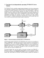
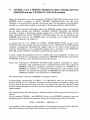
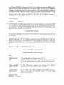
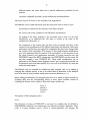
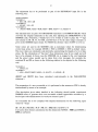
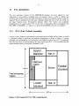
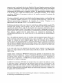
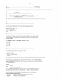
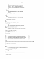
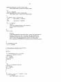
The TWODANT code is a modular computer program designed to solve the two-dimensional,
time independent, multigroup discrete-ordinates form of the Boltzmann transport equation. It
is based on the modular construction of the DANTSYS code system package /1/ which was
developed by the Los Alamos National Laboratory, Los Alamos, New Mexico, USA. This
modular construction separates the input processing including group constant preparation, the
solution of the transport equation and the postprocessing, or edit function, into distinct,
independently executable code modules, the INPUT, SOLVER, and EDIT modules,
respectively. These modules are connected to each other solely by means of binary interface
files (see Figure 1). In addition, interface files in ASCn format are used as problem input- and
cross-section-files and provided far the EDIT module as output files.
Input
Figure 1: General program and data flow in TWODANT.
Considering this modular construction of the TWODANT code it turns out to be sufficient to
replace in SIMMER the TWOTRAN-like program package essentially by the SOLVER part
of TWODANT. This is also advisable because a special process for the preparation of
macroscopic group constants is included in SIMMER, making use of results coming from the
SIMMER hydrodynamics part (for example number densities and temperatures for the
different reactor zones). All necessary information can then be provided on the binary
interface files and in specific COMMON areas.
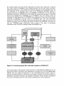
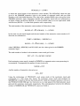
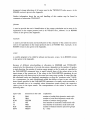
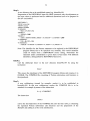
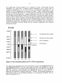
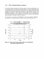
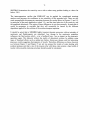
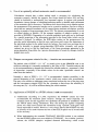
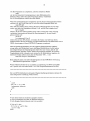
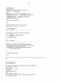
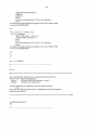
The general program flow and data transfer of the newly developed code SIMDANT is
represented in Figure 2. The linking module called LINKM was newly established. It gathers
all necessary information from SIMMER-ill COMMON areas for the preparation of the five
interface files which enable the TWODANT SOLVER module to perform the calculation of
7
the stationary adjoint and real and the instationary real neutron flux, respectively. Using the
flux values stored in COMMON areas, LINKM produces the flux files atflux and rtflux.
Additional information, as for exarnple the dynarnics parameter or time dependent terms for
the calculation of the extended source used in the TWODANT SOLVER module, is
transferred directly via COMMON areas from SIMMER to TWODANT. On the other hand,
information provided in TWODANT, as for exarnple the normalization integral, is transferred
directly from TWODANT to SIMMER also in COMMON areas. The leakage values are
calculated in LINKM and stored in COMMON areas, making use of the coarse mesh currents
calculated in TWODANT and also stored in COMMON areas. The main information
produced in TWODANT, the adjoint, real (scalar and angular) flux values, are written on the
interface files atflux, rtflux and raflxm and directly transferred into SIMMER, where they are
read into COMMON areas. Additionally, rtflux is used as flux guess in instationary
calculations in the TWODANT-package within the SIMMER code.
Figure 2: General program flow and data transfer in SIMDANT.
In the main program of the program system DANTSYS, called PRO GRAM DRNER, the two
dimensional transport calculation using TWODANT is initialized by a call of SUBROUTINE
TIGF20. The very complex prograrn flow of the outer/subouter/inner iteration scheme is
directed by TIGF20 taking into consideration the diffusion synthetic acceleration method, the
Chebycheff acceleration technique, the multigrid acceleration scheme and the controlling of
the various convergence processes. These tasks are performed in a lot of subroutines.
8
In addition, a great number of variables, COMMON values, and data arrays such as unit
numbers of extemal files, time information, machine specifications, storage capacities etc. are
initialized in DRNER and associated calls of subroutines belonging to the input package. In
order to assure the availability of all this information to the SOLVER part included in the
SIMMER package, it had to be constructed from an extract of PROGRAM DRNER, now
called SUBROUTINE TWODANT, and an extract of SUBROUTINE TIGF20 and all
subroutines and functions being called directly or indirectly from these two extracts. All
subroutine- and function-calls in these subroutines not being used for initializing the
SOLVER module itself or providing it with information have been suspended.
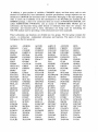
These subroutines and functions are divided into two groups. The first group contains the
system - or architecture - independent subroutines and functions. The names of these ones
belonging to the first group are:
ACOSH
BSREAD
COLL
DISKXS
DXITE
ERRORT
FCNG
FIXIT
FZERO
GREYACC
11MACH
ISORT
LINKMC
MACSCG
MCTOSN
MOMCOR
ONETBD
PRTLAG
PUTC
QRSGET
RDFCOF
RDQS
RESPJ
RTFLUX
RW
SETUP
SNMOM
SORTRI
SSPDI
SUMF2C
TFINAL
TFISCA
TINITQ
TLNLBC
ADJBNK
CALC
CONDIF
DMPFLX
EDTBAI
EXCEED
FCSRCE
FIXSRC
GAUELM
GRillS
IGPRNT
KEY
LINKO
MACTRC
MCXS
MULTIG
OPENRD
PRTNFX
PYTHAG
RIMACH
RDFIXS
RDSOL
RESSRC
RTGET
SCASTG
SFTFIX
SNSQ
SRCBAL
SSPEV
SUMNEG
TFINFM
TFRITE
TINP21
TLOCNW
ADVUK
CHEBY
CONSIST
DOGLEG
ELAPSE
EXPANQ
FDJACI
FS
GAUS8
GSUMFS
IMTQ12
KEYWRD
MACCOR
MASWEP
MCXSPT
MVBTOZ
OPENWR
PRTNGS
QBSGET
RIMPYQ
RDFLUX
REGCMV
REWASH
RTHSTI
SCASTH
SIGRAY
SNSRCMC
SRCCAL
SSPFA
SWDMPX
TFINP3
TGND25
TINP22
TMAPPE
AQFLUX
CHIMOD
CONVCK
DOUTER
ENORM
EXPCHI2D
FHLPR
FUN
GENBIN
HISTRY
INTADD
LCMADD
MACIN
MASWEPW
MESSAG
NEWPAS
PCMBAL
PT23D
QFORM
RIUPDT
RDGE02
RELAXR
RMGET
RTHST2
SCATTG
SINNER
SNTOMC
SRCDEF
SSWAP
SWFIX
TFINP6
TGSUMS
TINP23
TMOINIT
ASUMFS
CHKIFC
DESTDA
DWNSRC
EPXS2D
EXPXS2D
FHLPRL
FUN8
GETMSK
HKEEP
ISDAME
LGET
MACMIX
MASWMC
MFSFC
NOWERR
PRINTMC
PTFISS
QGET
RAN
RDGEOD
RELAXZ
RMHSTI
RTSRC
SCATTH
SMOM
SORTIA
SRCMC
STACKV
TESTGO
TFINQF
TIGF20
TINP24
TNEWPA
BINS
CIFLSM
DIFFO
DXEED
ERADDP
FCN
FILECK
FUN8D
GRDFN
HYLITE
ISITFC
LGNDRX
MACOUT
MCBFADJ
MGEODF
ONEGRP
PRNTIA
PTQID
QRFAC
RDASGM
RDMACR
RES FIT
RMHST2
RTTRCK
SCMADD
SNFLUX
SORTMC
SRCVAR
STOP
TESTSC
TFINSN
TINITA
TLCMBL
TOT28
9
TOT29
TRCK
TWODANT
XYRW
Table 1
TOUTER
TREADQ
UCFLUX
XYSCORE
TPNGEN
TRED3
VARACC
ZEROF
TQLRAT
TSMIXC
VRSION
LINKM
TRANS 0
TSNCON
XERMSG
TRBAK3
TSYNDI
XREP
Routines of the TWODANT SOLVER module (system and architecture
independent)
Most of these routines are original TWODANT routines, some of them had to be changed or
adapted, respectively, for SIMMER-relevant problems. These routines are:
CHEBY
DOUTER
MASWEP
SINNER
TINP22
CHIMOD
DRIVER
MASWEPW
TESTGO
TINP24
CIFLSM
HYLITE
PRNTIA
TFINAL
TOUTER
DESTDA
KEYWRD
PRTNFX
TIGF20
TRANS 0
DIFFO
LCMADD
RDSOL
TINITA
DMPFLX
MACMIX
SCMADD
TINP21
Two subroutines are completely new. The first one is LINKM. Its task is a kind of linkmodule between SIMMER and TWODANT. A detailed description of LINKM is given in
chapter 5. The second one is CHIMOD which modifies the fission spectrum for adjoint
calculations. It is described in more detail in chapter 7.3.
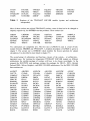
The second group of subroutines and functions consists of the system, - or architecture dependent ones. For running the independent TWODANT SOLVER module on different
architectures the suitable package of routines will have to be chosen accordingly. At the
moment the DANTSYS code package contains the packages for CRAY-, SUN-, Hewlett
Packard 9000-, Silicon Graphics-, and IBM / RS 6000 architectures. For the IBM / RS 6000
these routines are:
A4CRGT
C4S77D
COMPAT
DOPOFF
FEBYTE
IBM8HQ
ISAMAXT
ISCHOL
ISHOLE
LHKYIN
LODBCL
LODERP
LODORI
LODRTP
LODSTH
MOV8T8
NUMIGT
PUNDTF
RANYEQ
RDCI6
AB4CRD
CLEAR
CRAYOF
DRED8
FILLU
IBM8R8
ISCHA
ISCHOT
ISMAX
LHKYOT
LODBLK
LODERR
LODPRV
LODSCH
LODSTO
MPLY
NXTSGE
PUNFIDO
RANYGT
RDCR18
ADJLCM
CLEAR4
CRYATX
DRIT8
FIXFLT
IKCCN
ISCHD
ISCHOU
ISMIN
LLDINP
LODBMV
LODINT
LODQER
LODSEQ
MCRED
MSGBOX
OFFUGO
R8THLD
RANYLE
REED
ANLVER
CLEARX
DOPC
DST4C
HOLCVT
IKCR8N
ISCHE
ISCHP
ISUMI
LLHCVS
LODBNI
LODITP
LODQRD
LODSET
MDOPC
NAFIX
ORDTUP
R8THOL
RANYLT
RUT4C
ASCOPW
CLOSEQ
DOPCA
EFBYTE
IANYGT
IKR8CN
ISCHL
ISCHS
LCMCHK
LLHSET
LODCKT
LODJCA
LODRDC
LODSHC
MDRED
N4FIX4
PA9A12
R8XHLD
RANYNE
SASUM
AUN4C
CLRLCM
DOPCBD
ENVSET
IBM4HQ
IKR8R8
ISCHLF
ISDAMA
LCMSET
LOD7BD
LODCTB
LODORC
LODRTA
LODSPU
MOV4T4
NSGBOX
PRTTRN
R8XHOL
RDCHR8
SATXOF
10
SAXPY
SEEK4C
SGESLA
SLDFNA
SSUM
SUBWR
TIMER
WDCHR8
SCMSEC
SEEKBD
SHTOFF
SLDNAA
STNAA
SUNASG
TRNSUM
WDCI6
SCOPY
SEKEST
SIDRD
SPBFA
STOPIT
SUNOFF
UGOLOC
WDCR12
SDOT
SEKPHL
SIGZFB
SPBSL
STOPLD
SWFILE
UGONOW
WDCR18
SECNDS
SGECO
SKOPRD
SREED
STRIP
T1LOAD
USERDA
SECONI
SGEFA
SKOPWR
SSCAL
SUBRD
TIMDAT
WATRMD
Table 2 Routines of the TWODANT SOLVER module (system or architecture dependent)
All routines mentioned above are originally TWODANT ones except for two. A function
named ISAMAX and a subroutine named ERROR as weIl are included in TWODANT and
exist in SIMMER-III, too, with the same names. So the names of the TWODANT routines
were changed into ISAMAXT and ERRORT, respectively.
140 COMDECKs, in the terminology of HISTORIAN, which contain PARAMETER- and
COMMON-blocks, declaration-, DIMENSION- and EQUIVALENCE-statements are used in
the subroutines of Table 1 and Table 2. These COMDECKs are:
ALITLE
BSTYPE
CMTRANS
EDLCM
FMIXC
GEONAMD
RILITE
IPSPEC
LNCONS
LONGHL
NCSZCX
OIAEEQ
ONEM18D
ONEM8DS
PARAMT
PNTR18
REAIA
SCOMPS
SOLINR
STKFCK
THSTRY
TWOM1DS
XBIG
ANG
AVGNUM
BULLSH
COMECS
EDSTR
FOURDS
GMSIZE
IA
ISPC
LNSINP
LSCRAT
NCSZFN
OIAI
ONEM2DS
ONEM9DS
PIDS
PNTR19
RESOL
SCRATMO
SPECEQ
STKNER
TIA
UNDWR
XLITLE
BCDUNT
CHEBYDS
COMEK
ERRORS
GCHECKS
GOMODS
IBMPCX
ISPCEQ
LNSTAL
MISC
NDIM1
OIAIEQ
ONEM3DS
ONEP20D
PNTRll
POST31
RMDM
SEEKGEN
SPECXS
STKSTO
TIAN
UNTAP
XSDECK
BDNAME
CM
COMINP
FACESC
GCOUNTS
HALFDS
IBMSTF
JDSPEC
LOCAL
MVLCK
NWPASS
OIAIN
ONEM4DS
ONEP2DS
PNTR12
POWER
RUSS
SHORTU
SQRT3DS
SYSBET
TINY
VECT
XTRAS
CNFIX
Table 3 COMDECKs of the TWODANT SOLVER module
BDTYPE
CMBDCK
DIMENT
FIVEDS
GDSTIO
HED
INARRY
L500
LODFLG
NCSIZE
OBJECTS
ONEDS
ONEM5DS
ONEP4DS
PNTR13
PRESIZN
SAD2SV
SHSTRY
STACK
SYSTM
TRANSI
VRDATE
ZERODS
BSNAME
CMMESH
DOTRANC
FIVEM5D
GEONAM
HIDDEN
INSTAL
LENLPEN
LONERR
NCSZ80
OIAE
ONEMlOD
ONEM6DS
ONEP9DS
PNTR14
PRNTIDO
SAVMON
SOLIND
STGDAT
THREEDS
TRANST
VSCONS
MISC1
11
Conceming the unit reference numbers a change was necessary. In SIMMER-Ill the SIMBF
file is written by using the unit reference number 10. This unit reference number is used in
TWODANT as weIl. Because of the complicated file handling in TWODANT the unit
reference number of the SIMBF file in SIMMER was changed to BFU = 77.
By assembling the subroutines and functions of Table 1 and Table 2, respectively, an
independently running TWODANT SOLVER module was prepared. By running the
TWODANT code in the framework of the DANTSYS code system the five binary interface
files adjmac, asgmat, geodst, macrxs, and solinp were provided and stored for longterm use.
These five interface files contain all information necessary to run the independent
TWODANT SOLVER module, too. Identical results of the TWODANT SOLVER module
and the original separate TWODANT run for preparing the interface files can be taken as a
proof that the TWODANT SOLVER module has been constructed correctly.
12
4.
Short description of the binary interface files connecting the
TWODANT SOLVER module with the other TWODANT
modules INPUT and EDIT
The SOLVER module of TWODANT is capable to run independently of the DANTSYS
system code package as described in chapter 3, provided that it has access to five binary
interface files containing all necessary information for its regular program flow. (Some minor
deviations compared to a standard TWODANT run regarding printing of results related to
documentation of the input and the iteration protocol or some aspects of the complicated file
handling capabilities have to be conceded, but the correspondence of the final results with
TWODANT in DANTSYS could be proved far all cases under consideration.)
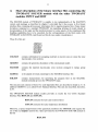
These five files are:
ADJMAC
ASGMAT
GEODST
MACRXS
SOLINP
ASGMAT
contains information for assigning materials to reactor zones to create the zone
macroscopic cross sections.
GEODST
contains the geometry description of the calculational model.
MACRXS
contains the material macroscopic cross sections arranged in energy group
order.
ADJMAC
is the adjoint-reversed counterpart to the MACRXS interface file.
SOLINP
contains characteristics for specifying the program flow in the SOLVERmodule normally given in the TWODANT input.
The structure and contents of these five code-dependent files are described in detail in /1/. In
addition GEODST is a so called CCCC Standard Interface File and also described, therefore,
in /5/.
The TWODANT SOLVER module usually provides as results the two CCCC Standard
Interface Files RTFLUX and ATFLUX.
RTFLUX contains the real scalar neutron fluxes
ATFLUX contains the scalar importance distribution
Moreover, a special improvement of the quasistatic method in the SIMMER code requires the
use of the real angular neutron flux values provided by the TWODANT SOLVER module in
the file
RAFLXM
13
which is described in detail in /1/. The ordering sequences and the mesh-oriented positions for
these fluxes are also mentioned there. The details of the application of angular neutron fluxes
are described in chapter 7.2. These three interface files are associated with the following
Fortran reference numbers:
IRTFLI
51
IATFLI = 50
IRAFL = 11
It may be worthwhile to mention that the calculation of p-tables is still done in the previous
manner. It is performed on the basis of the direct and adjoint scalar fluxes and the suitably
weighted leakage rates. The complication needed for implementing a refined method based on
transport perturbation theory which would -in principle- be feasible was not considered to be
worthwhile because its effect was expected to be negligible but would require a major
revision in SIMMER and the permanent storage of the adjoint angular flux and its inclusion in
the restart file.
14
5.
LINKM, a new LINKING-Module for data exchange between
SIMMER and the TWODANT-SOLVER module.
Nearly all information to run the independent TWODANT SOLVER module as part of the
SIMMER code is contained in specific SIMMER COMMON-blocks and data areas.
Therefore, it is not advisable to specify a special user input. For that purpose it was decided to
establish a so-called linking module as an interface. This linking module is called LINKM.
LINKM collects necessary information taken from SIMMER storage locations and prepares
the five binary interface files ADJMAC, ASGMAT, GEODST, MACRXS, and SOLINP
described in chapter 4 allowing the regular program flow of the SOLVER-module. For the
small information part for the TWODANT SOLVER-module that was not included in the
SIMMER input up to now, the SIMMER input was extended, as for example the AWDDparameters (explanation see chapter 8).
A second task has to be fulfilled by LINKM. SUBROUTINE INNET as part of the
TWOTRAN-like code package (being now replaced by the TWODANT SOLVER-module)
contained a program part calculating the leakage values for the reactor system needed for
reactivity determination. As no comparable program part is provided in the TWODANT
SOLVER-module, LINKM is extended to calculate these particular terms.
In order to make the preparation of the five interface files more transparent, it seems to be
necessary to describe the correspondence between the SIMMER fluid-dynamics grid and the
TWODANT neutronics coarse and fine mesh grid in more detail.
PIease note: Although the TWODANT SOLVER-module performs calculations in various
geometries, only 2-dimensional XY- and RZ-geometries have been realized in
SIMMER. Neutronics calculations performed currently by TWODANT in
SIMMER are restricted to 2-dimensional RZ-geometry. (The geometry index
IGEOM = 0 is related to RZ-geometry in SIMMER; this index is transformed in
LINKM into IGOM = 7 for transmission to TWODANT.)
The fluid dynarnics mesh grid in SIMMER is arranged as folIows:
In RZ-geometry, characterized by IGOM = 7 in TWODANT, there are IB columns in Rdirection and JB rows in Z-direction. The meshes within the grid are counted by starting with
the first mesh at the lower left edge in the first row, going to the right up to the IB-th mesh
and then running through the rows from the first at the lower boundary to the JB-th row at the
upper boundary.
The relation between the fluid dynamics- and the neutronics coarse mesh grid is then given as
folIows:
For the numbers NREGB(1) and NREGB(2) given in the SIMMER neutronics input and
designating the first and the last neutronics mesh in the fluid dynamics grid in R-direction
ITMPI
= NREGB(2) -
NREGB(l) + 1
is the number of fluid dynamics meshes related to the neutronics coarse grid in this direction.
Each fluid dynarnics mesh length in this direction can be divided by a factor of
15
NCRAD(I), I = 1,ITMP1
to obtain the mesh lengths of the neutronics coarse meshes. The NCRAD(I) values are also
given in the SIMMER neutronics input as the number of neutronic mesh cells per fluid
dynarnics cell in the radial direction. The value of the variable IDNR, also to be given in the
SIMMER neutronics input, determines whether the neutronics mesh cells are constructed as
an equal volume sub-division (IDNR = 0, used as default value) or as an equal mesh width
sub-division (IDNR = 1) of the fluid dynarnics cells, respectively.
The total number of the neutronics coarse meshes in R-direction is then
INCMX =IT =
L
NCRAD(I)
I = 1,ITMP1
In the same way the mesh lengths and the total number of the neutronics coarse meshes in Zdirection are calculated as:
ITMP2 = NREGB(4) -NREGB(3) +1
INCMY = JT = L NCAXI(J)
J = 1,ITMP2
where NREGB(4), NREGB(3) and NCAXI(J) are also values given in the SIMMER
neutronics input.
The total number of meshes in the neutronics coarse mesh grid is then
ITJT = IT
* JT = INCMX * INCMY
Each neutronics coarse mesh is treated in SIMMER as aseparate reactor zone possessing its
own material. Consequently the number of zones is given by
NZONE=ITJT
And the number of materials is also given as
MT = ITJT
Using the terminology of TWODANT, each coarse mesh of the neutronics mesh grid
corresponds to a fine mesh; this means, the neutronics coarse mesh grid prepared by
SIMMER-ill is identical with the fine mesh grid for which the transport equation is solved in
the TWODANT-SOLVER part. So, from now on, we only speak of the fluid dynarnics mesh
grid and the neutronics mesh grid, respectively. The correspondence between the different
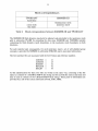
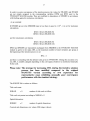
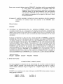
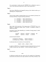
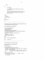
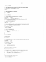
meshes in SIMMER-ill and TWODANT is shown in Table 4.
16
Mesh correspondences
Table 4
TWODANT
SIMMER-III
stand-alone
--coarse mesh
fine mesh
fluiddynamics mesh
neutronics mesh
---
Mesh correspondence between SIMMER-III and TWODANT
The SIMMER-ill fluid dynamics mesh grid is adjusted code-intemally to the neutronics mesh
grid in subroutine PSARR by extending the data areas XMESHB and YMESHB, initially
containing the fluid dynamics mesh boundaries, to the neutronics mesh boundaries in both
directions.
For each material and, consequently, für each neutronics mesh a set of self-shielded group
constants is provided by SIMMER in subroutine SHLDXS and its associated subroutines.
The five interface files are associated with the five Fortran unit reference numbers
IADJMA
IASGMA
IGEODS
IMACRX
ISOLIN
=
=
=
=
=
41
43
44
42
45
All file identifications für these five files are written in the same way, consisting of the file
names as contents of a CHARACTER*8 data string and für each file the same actual date and
time is used as contents of two CHARACTER*8 data strings. These parts of information are
provided by a call of the system subroutine DATE_AND_TIME.
17
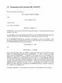
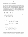
5.1 Preparation of the interface file ASGMAT
The file control block is written as
MT, NZONE, MPZTOT, FMMIX
with
MT = NZONE = ITJT
as shown above.
As a result of specifying
MPZTOT = FMMIX = 0,
TWODANT is run with the IN-SOLVER mixing table length = 0 and prescribing NO fraction
mixing by fine mesh.
As compatibility code words CODE1 and CODE2, the same CHARACTER*8 data strings are
written as already used in the file identification, containing the actual date and time.
As for SIMMERITWODANT the assignment of materials to zones is very simple - each
mesh in the neutronics grid represents one reactor zone possessing its own specific material two CHARACTER*8 data strings are prepared as
MATNAM(I), 1= 1,MT
and
ZONNAM(I), I = 1,NZONE
They contain the labels 'ISO' and 'ZONE', respectively, followed by the neutronics mesh
number in CHARACTER representation. MATNAM(I), I = 1,MT is written as material
names block and ZONNAM(I), i = 1,NZONE as zone names block on the ASGMAT file,
respectively. The number of material names and the number of zone names are limited in
subroutine LINKM by the variable DMAT which could be set in a PARAMETER statement
to a value of 10, 100, 10000r 10000, with DMAT = 1 000 as adefault value at present. If the
currently implemented maximum value of DMAT = 10 000 has to be increased, subroutine
LINKM has to be extended in the same way as is implemented for the values of 10, 100,
1000, and 10 000, respectively. (Possibly some FORMAT-statements, currently restricted to
'14', will have to be modified, too.)
According to MPZTOT = 0, the further blocks fore seen for the ASGMAT file are omitted.
18
5.2
Preparation of the interface file GEODST
The GEODST file is written according to its description given in /11 and as a subset of the
description given in 15 I.
It has to be noticed that according to the tenninology of SIMMER in the TWODANT
SOLVER module, the number of fine meshes is always equal to the number of coarse meshes;
this means equal to the number of neutronics meshes, as described above. Each mesh in the
neutronics grid represents aseparate reactor zone as region possessing its own specific
material which is assigned to a set of macroscopic group constants provided by SIMMER in
subroutine SHLDXS and its associated subroutines.
The file specifications in the first record of GEODST are set logically according to its use in
SIMMERITWODANT in the following way, using the designations above:
IGOM
NZONE
NREG
NZCL
NCINTI
=IT
NCINTJ
=JT
NCINTK
=1
NINTI
=IT
NINTJ
=JT
NINTK
=1
=7
=ITJT
=ITJT
=0
index for RZ-geometry
number of zones
I
in accordance with the number
number of regions
I
of meshes in the neutronics grid
not relevant for SIMMERITWODANT
number of neutronics meshes in R-direction (number of coarse
meshes in the meaning of TWODANT)
number of neutronics meshes in Z-direction (number of coarse
meshes in the meaning of TWODANT)
number of neutronics meshes in the third dimension; set = 1 for 2dimensional problems
number of neutronics meshes in R-direction (number of fine
meshes in the meaning of TWODANT)
number of neutronics meshes in Z-direction (number of fine
meshes in the meaning ofTWODANT)
number of neutronics meshes in the third dimension; set = 1 for 2dimensional problems
Please note: In accordance with the SIMMER treatment of preceding versions, no flexibility
regarding geometry and boundary conditions is allowed, i.e. the application is
currently restricted to RZ-geometry and vacuum boundary conditions on all
outside surfaces, assuming reflective boundary conditions at the cylinder axis.
In subroutine LINKM the GEODST and the SOLINP files for the TWODANT SOLVER
module are prepared based on these assumptions. As a consequence, simplified mathematical
models having symrnetry with respect to the core midplane have to be treated without taking
advantage of that symrnetry property.
IMB1
=1
IMB2
=2
JMB1
=2
first boundary condition in R-direction; means reflective boundary
condition
last boundary condition in R-direction; means extrapolated
boundary condition (diffusion; grad <D / <D = - C / D where C is
given as BNDC below and D is the group diffusion constant. This
means: no entering of neutrons.
first boundary condition in Z-direction; means extrapolated
19
JMB2
=2
KMB1
KMB2
NBS
NBCS
=0
=0
=0
=1
NIBCS
=1
NZWBB
NTRIAG
NRASS
NTHPT
NGOP(I),I=l,4
=0
=0
=0
=0
=0
boundary condition.
last boundary condition in Z-direction; means extrapolated
boundary condition
not relevant for 2-dimensional problems
not relevant for 2-dimensiona1 problems
number of buckling specifications (no specifications are given)
number of constants for externa1 boundaries (one single value is
used everywhere)
number of constants far internal boundaries (one single value is
used everywhere)
no reactor zones are black absorbers
not relevant for RZ-geometry
region assignments to coarse meshes
not relevant for RZ-geometry
reserved far further use in GEODST file
For 2-dimensional problems the second record of the GEODST file is not used.
In the third record - using the TWODANT terminology - the 2-dimensional coarse mesh
interval boundaries and the numbers of fine meshes per coarse meshes are put together.
Keeping in mind that in the SIMMER neutronics grid the TWODANT fine mesh grid is
identical with the coarse mesh grid, the number of coarse mesh boundaries in both
directions are precalculated as folIows:
NCBNDI = IT + 1
NCBNDJ = JT + 1
The coarse mesh boundaries are then
(XMESHB(I), I = 1,NCBNDI)
(YMESHB(J), J = 1,NCBNDJ)
(IFINTS(I) = 1, i = 1,NCINTI)
(JFINTS(J) = 1, J = 1,NCINTJ)
written on the GEODST file as follows:
coarse mesh boundaries far R-direction
coarse mesh boundaries for Z-direction
number of equally spaced fine mesh intervals
mesh interval in R-direction (set =1, for
meshes are equal to fine meshes)
number of equally spaced fine mesh intervals
mesh intervals in Z-direction (set = 1, far
meshes are equal to fine meshes)
per coarse
all coarse
per coarse
all coarse
The values for XMESHB and YMESHB for this data block are taken from SIMMER-own
data areas. As SIMMER is based on the application of an Eulerian grid, the values of
XMESHB and YMESHB remain unchanged during a calculation of a reactor transient.
The fourth record of the GEODST file is not relevant far 2-dimensional calculations.
The fifth record contains geometry data and has to be present for all geometries IGOM .GT. O.
VOLR(I),
1= 1,NREG
BSQ
region volumes for the neutronics mesh grid - they are transformed to a
single precision representation from a SIMMER-own data area in double
precision representation
not transformed according to NBS = 0 (see above)
20
BNDC
=0.4692
BNCI=O.
NZHBB
NZC(I) = 0,
1= 1,NZONE
NZNR(I) =1,
1= 1,NREG
boundary constant (grad <D I <D = - C I D ---> - D· grad <D = <D 1(3' K)
using K = 0.7104 (extrapolation length known from the Milne problem)
--> 1 / (3 . K) = C = 0.4692) one value according to NBCS = 1
(see above)
internal black boundary constant - one value according to NIBCS = 1
(see above)
not transmitted according to NZWBB = 0 (see above)
zone classification
zone number assigned to each region
In the sixth record the region assignments to the neutronics meshes are specified. This record
has to be present for IGOM .GT. 0 .AND. NRASS . EQ. 0 (see above).
1,1= 1,NREG
region numbers assigned to the neutronics meshes
The following records intended for the GEODST file are omitted according to the values
given in the specification record.
21
5.3 Preparation of the interface files MACRXS and ADJMAC
The MACRXS and the ADJMAC files are written according to their descriptions given in 11 I.
As described above, sets of self-shielded group constants are calculated in SIMMER in
subroutine SHLDXS and its associated subroutines for all meshes of the neutronics grid.
Considering NEU and NEIGM as the maximum allowed number of meshes in the neutronics
grid and the maximum allowed number of energy groups, respectively, the macroscopic
principal group constant types previously prepared in SIMMER are stored in the
COMMON ICELXSI data areas
CELFIS(NEI J,NEIGM)
CELREM(NEI J,NEIGM)
nu * fission cross section NUSIGF
total cross section TOT AL
The fission spectrum CHI and the neutron velocities VEL are stored for all energy groups in
the
COMMON IRINCONI data areas
CHI(NEIGM + 1)
VELCTY(NEIGM)
prompt fission spectrum CHI
neutron velocities VEL
In addition to these principal neutronics data, the TWOTRAN SOLVER module also expects
the absorption cross section ABS because it is needed for determining the meshwise neutron
balance. Therefore, the COMMON ICELXSI is extended by the data area
CELABS(NEU ,NEIGM)
absorption cross section ABS
for storing the absorption cross section for all meshes of the neutronics grid and all energy
groups.
The macroscopic self-shielded absorption cross sections are calculated in an extension of
subroutine SHLDXS and its associated subroutines analogously to the macroscopic selfshielded fission and capture cross sections as
CELABS(I J,GRP)
= L(DENISO(I J,M) * VF
* (XSISO capt (M,GRP) * FFISOcapt (I J,M)
+ XSISO fis (M,GRP) * FFISOfis (I J,M»)
where
DENISO(I J,M)
is the number density of isotope M in mesh I J
VF
is a factor for the approximate treatment of heterogeneity effects
for thermal neutron reactors. In case of fast neutron reactors: VF =
1.
22
XISOcapt(M,GRP),
XISOfis(M,GRP)
are the microscopic capture and fission cross
respectively, for isotope M and energy group GRP
sections,
FFISOcapt(I J,M),
FFISOfis(I J,M)
are the capture and fission resonance self-shielding factors (ffactors), respectively, for isotope M in mesh I J for the energy
group being considered
Please note: capture here means all absorptions, excluding fissions, i.e. including e.g. (n,p)-,
and (n,a)-reactions.
The self-scatter and the downscatter cross sections are stored in SIMMER in the
COMMON /CELXS/ in the data areas CELSCT(NED,NEIGM) and in
CELDWN(NED,(NEIGM*(NEIGM-l)/2)), respectively.
For reasons of simplicity the whole lower triangular scattering matrix is transferred from
SIMMER to the TWODANT SOLVER module via MACRXS and ADJMAC files. If no
other values are present, i.e. in case of an empty matrix entry, a 0.0 is transferred. The
corresponding control numbers for the TWODANT SOLVER module are transferred
according to the specifications of the file control blocks.
The file MACRXS is written as follows:
File control block:
NGROUP
NMAT
=IGM
=ITJT
NORD
NED
IDPF
LNG
=1
=0
=1
=IGM
MAXUP
MAXDWN
NPRIN
=0
=IGM-l
=4
I2LPl
=0
number of energy groups
number of materials in accordance with the number of
meshes in the neutronics grid
number of Legendre scattering order
number of EDIT cross sections
cross section data are of double precision
number of last neutron group (no coupled neutron/gamma
cross section set)
no upscatter groups
maximum number of downscatter groups
the four basic principal cross sections which have to be
always present for TWODANT SOLVER calculations
the (2L + 1) term for the higher order moments of the
scattering matrix is not included in the library
File data:
HMAT(I) = MATNAM(I)
HED(1) = CHI
HED(2) = NUSIGF
HED(3) = TOTAL
HED(4) =ABS
VEL(N) = VELCTY(N),
N= 1,IGM
EMAX(N) = 0.0,
N= 1,IGM
material labels as described in 5.1
label for fission spectrum
label for production (nu*fission) cross section
label for total cross section
label for absorption cross section
mean neutron velocities for all energy groups
upper energy bounds of groups; not necessary for SIMMER
calculations and, therefore, transferred as O.OD+OO for all
values
23
lower energy bound of set; not necessary for SIMMER
calculations and, therefore, transferred as O.OD+OO
EMIN=O.O
For all energy groups NG from NG = l,IGM, i.e. according to decreasing energy, the cross
section values are written on file MACRXS in the following way:
Principal cross sections for energy group NG (to be given for all meshes of the neutronics
grid):
CHI(I,NG), 1= 1,NMAT
CELFIS(I,NG), 1= 1,NMAT
CELREM(I,NG), I = 1,NMAT
CELABS(I,NG), 1= 1.NMAT
fission spectrum CHI
production (nu*fission) cross section NUSIGF
total cross section TOTAL
absorption cross section ABS
The scattering control block for energy group NG is written in the following way:
«NGPB(L,J), L = 1,NORD), J = 1,NMAT)
With regard to NORD = 1 according to the value given in the control block, and in
consideration of the transfer of the whole lower triangular down-scauering matrix, this means
NGPB(L,J) = (NG,J=l,NMAT)
specifying NG as the number of groups scattering into the considered group NG.
(IFSG(L,J), L = 1,NORD), J = 1,NMAT)
with
IFSG(L,J) = (NG, J=l,NMAT)
defining NG as the group number of the first source group scattering into the considered
group NG. Le. the first value refers to the self-scatter term (within-group scattering), the next
value to scattering from group NG - 1 to group NG, etc..
For the first group, this means NG = 1, in case of the MACRXS file, only the within-group
scattering cross sections are transferred according to
(CELSCT(I,NG), I = 1,NMAT)
For all other groups the within-group scattering cross sections and the down-scattering cross
sections are transferred with
NGG = (NG - 1) * (NG - 2) / 2
(CELSCT(I,NG), I = 1,NMAT
«CELDWN(I,NGG+J), J = 1,NG-l), 1= 1,NMAT)
24
where the energy of the source group increases with increasing J.
The ADJMAC file contains the same data, but they are arranged in inverse group order, i. e.
according to increasing energy.
The file control block and the file data as written on the ADJMAC file are identical with the
MACRXS file.
The principal cross sections are written for all energy groups NG in the inverse group order
NG = IGM,1,-1 (to be given for all meshes ofthe neutronics grid)::
CHI(NG), 1= 1,NMAT
CELFIS(I,NG), 1= 1,NMAT
CELREM(I,NG),I = 1,NMAT
CELABS(I,NG), 1= 1,NMAT
fission spectrum CHI
production (nu*fission) cross section NUSIGF
total cross section TOTAL
absorption cross section ABS
The scattering control block for energy group NG is written, also observing the inverse group
order, as folIows:
((NGPB(L,J), L = 1,NORD), J = 1,NMAT)
With regard to NORD = 1 according to the value given in the control block and in
consideration of the transmission of the whole lower triangular down-scattering matrix this
means
NGPB(L,J) = ((IGM-NG+1), J=1,NMAT)
specifying NG as the number of groups scattering into the considered group NG.
((IFSG(L,J), L = 1,NORD), J = 1,NMAT)
with
IFSG(L,J) = ((IGM-NG+1), J = 1,NMAT)
defining NG as group number of the first source group scattering into the considered group
NG.
For the first group, this means NG = IGM in the case of the ADJMAC file, only the withingroup scattering cross sections are transferred according to
(CELSCT(I,NG), 1= 1, NMAT)
For all other groups NG, NG running from IGM - 1 to 1, the within-group scattering cross
sections and the down-scattering cross sections are transferred to the ADJMAC file as
(CELSCT(I,NG), I = 1,NMAT)
((CELDWN(I,NGG + J*NG + J*(J -1)/2), J = 1,(IGM - NG), 1= 1,NMAT)
25
where
NGG = (NG -1)
* (NG -
2) / 2
and the energy of the source group decreases with increasing J.
26
5.4
Preparation of the interface file SOLINP
Before writing all necessary infonnation for controlling the pro gram flow in the SOLVER
module of TWODANT on the SOLINP file some integer and real variables are to be set
properly in subroutine LINKM according to the TWODANT application in SIMMER for the
actual problem being calculated. It has to be noticed that the values for some variables are
sometimes set differently from the default values given in TWODANT as a consequence of
findings gained from previous SIMMER calculations.
The variable IAFLUX indicating whether the regular angular flux file RAFLUX has to be
written or not is set according to the kind of calculation: Yes (IAFLUX = 1) for direct and No
(IAFLUX=O) for adjoint calculations.
All infonnation conceming 'controls and dimensions' as well as 'floating input data' has to be
written twice on the SOLINP file as raw and defaulted values, respectively. Therefore, two
variables, ISTART and ISTARTD are used to transmit the infonnation from SIMMER to the
TWODANT SOLVER module whether a flux file from a preceding run may be used as flux
guess for the actual calculation. In the case of stationary direct or adjoint calculations no flux
guesses that could be used are available. Therefore, it is set
ISTART
ISTARTD
=
=
0
0
whereas for instationary calculations the form of two flux shapes calculated in successive
runs is not too different so that the result of the preceding run can be used as flux guess for the
succeeding one in order to save computing time and it is, therefore, set
ISTART
ISTARTD
=
=
1
4
In subroutine PRNTIA of TWODANT this infonnation is used to switch the variable
INFLUX = 0 to INFLUX = 1, assigning that a flux guess is to be read from the file RTFLUX,
in accordance with this variable nonnally given in the input for stand-alone TWODANT
calculations.
Note: Due to the favorable perfonnance of TWODANT, the various options (available when
using the TWOTRAN package) for specifying a suitable starting guess for the source
distribution were suspended.
Aseries of variables is given in the SIMMER neutronics input for controlling the different
iteration processes. Four of them have to be transmitted to the TWODANT SOLVER module
in order to control the iteration processes for calculating the neutron flux shapes:
EPSO
EPSMIN
ITLMOU
ITLMIN
the convergence precision for the total fission source
the minimum convergence precision for inner iterations
the maximum number of outer iterations permitted
the maximun number of inner iterations per group
permitted per outer iteration when fission source is near
convergence
27
In order to assure convergence of the iteration process the values for ITLMOU and ITLMIN
are not simply assigned to the corresponding variables OITM and IITM used in the
TWODANT SOLVER module. They are modified in dependence of EPSMIN in accordance
with findings gained in numerous calculations.
As an example:
If EPSMIN given in the SIMMER input is less than or equal to 1.10-8 , it is set for stationary
calculations
IITM
OITM
=MAX (ITLMIN,50)
IITM
OITM
=MAX (ITLMIN,50)
= MAX (ITLMOU,50)
and for instationary calculations
= MAX (ITLMOU,30)
EPSO and EPSMIN are transmitted unchanged from SIMMER to the TWODANT SOLVER
module as given in the input; IITL as the maximum number of inner iterations per group at
the beginning of the iteration process is set
IITL = 1
and thus is coinciding with the default value given in TWODANT. During the execution of a
run, IITL is suitably changed depending on the convergence behavior as monitored intemally
by the code.
Please note: The strategy for increasing IITL during the iterative solution
process has been modified compared to the original
DANTSYS version according to own experience for
representative cases exhibiting unusually poor convergence
performance with the standard strategy.
The SOLINP file is written as follows:
Title card count:
NHEAD
=0
number of title cards to follow
Title card, not present according to NHEAD = 0
Spatial dimension:
IDIMEN
=2
number of spatial dimensions
Controls and dimensions, raw values (200 integer values):
28
(For SIMMER applications some data are not relevant but the associated explanation is given
for completeness.)
IEVT
ITH
ISCT
ISN
IQUAD
ISTART
ICSM
INCHI
IBL
IBR
IDENX
IPVT
12ANG
IQOPT
IQAN
IQL
IQR
OITM
IITL
IITM
ITLIM
I1
FLUXP
XSECTP
FISSPR
SOURCP
GEOMP
IANGP
IACC
IRMFLX
IGRPSN
IAFLUX
ISBEDO
IBALP
DUM3
IBB
IBT
IITLD
IQT
IQB
IXM
IYM
IZM
IDENY
type of TWODANT calculation
o/ 1 direct / adjoint calculation
Legendre order of scattering
angular quadrature order as given in the SIMMER input
source of quadrature set, built-in constants are used
flux guess flag, as described above
o/ 1 - no / yes in-sol ver mixing
o/ 1 / 2 none / one chi / zonewise chi
o / 1 / 2 / 3 / 4 - left boundary condition, 'reflective' used for zaxis
0/ 1 /2/ 3 /4 - right boundary condition, 'vacuum' used
=0
o/ 1 / 2 - none / fine mesh density factors by XMESH / fine mesh
=0
density factors for every mesh
type
of eigenvalue to search for in a concentration or dimension
=0
search. 0 / 1 / 2 - none / keff / alpha
o/ 1 - no / yes do 2 angle slab calculation
=0
o/ 1 / 2 / 3 / 4 / 5 / 6 - inhomogeneous source option
=0
inhomogeneous Legendre order
=0
-1 / 0 / 1 / 2 / 3 / 4 / 5 - left boundary source option
=0
-1 / 0 / 1 / 2 / 3 / 4 / 5 - right boundary source option
=0
outer iteration limit - see explanations above
=OITM
early inner iteration limit - see explanations above
=IITL
near convergence inner iteration limit - see explanations above
=IITM
time limit in seconds.(O = default value - unlimited)
=0
not used
=0
o/ 1 / 2 - none / isotropie / all moments - final flux print flag
=0
o/ 1 / 2 - none / principal / all cross section - print flag
=0
o/ 1 - no / yes fission rate - print flag
=0
o/ 1 / 2 / 3 - no / as input / normalized / both - source print flag
=1
o/ 1 - no / yes - fine mesh geometry print flag
=0
o/ 1 - no / yes - angular flux print flag
=0
acceleration type
=0
o/ 1 - no / yes - write code- dependent zone fluxes flag
=0
0/1 - no / yes - group dependent SN orders (GRPSN) read in flag
=0
=IAFLUX o/ 1 - no / yes - write angular flux file RAFLUX - see explanation
above
albedo option
=0
print both: balance tables and flux fixup monitor for coarse meshes
=3
not used
=0
o/ 1 / 2 / 3 / 4 - bottom boundary condition, vacuum used
=0
o/ 1 / 2 / 3 / 4 - top boundary condition, vacuum used
=0
time limit in seconds (0 = default value - unlimited)
=0
-1/0/1/2/3/4/5 - top boundary source option
=0
-1 / 0 / 1 / 2 / 3 / 4 / 5 - bottom boundary source option
=0
o/ 1 - no / yes - radial modifiers for x
=0
o/ 1 - no / yes - radial modifiers for y
=0
o/ 1 - no / yes - radial modifiers for z
=0
o/ 1 - no / fine mesh density factors by ymesh
=0
=1
=IAD
=0
= ISNT
=0
= ISTART
=0
=0
=1
30
2.
3.
Usually the influence of the delayed neutrons and their precursors is
taken into account in SIMDANT but not in TWODANT.
The user should be aware that TWODANT destroys the SOLINP file
before the end of its execution; thus, in a UNIX environment it is
recommended to perform the TWODANT runs in aseparate directory.
Floating data in double precision, raw values (200 values):
EV
NORM
EPSO
EPSI
BGHT
BWTH
EVM
=O.D+O
= O.D+O
= EPSO
= EPSMIN
=O.D+O
= O.D+O
= O.D+O
PV
=O.D+O
XLAL
=O.D+O
XLAH
= O.D+O
XLAX
=O.D+O
POD
= O.D+O
EPSR
= O.D+O
EPSX
=O.D+O
EPST
= O.D+O
D(I),I=1,10 =O.D+O
E(I),I=1,5
=O.D+O
TRCOR
= O.D+O
PLANET
=O.D+O
FCSRC
=O.D+O
XMCSB
= O.D+O
XMCBLT
=O.D+O
FCWCO
= O.D+O
D(I),I=1,54 = O.D+O
EXTRAS (I) =O.D+O
,I = 1, 110
eigenvalue guess
normalization constant
outer iteration convergence criterion, see explanation above
inner iteration convergence criterion, see explanation above
buckling height
buckling width
eigenvalue modifier
parametric value
lambda lower limit for searches
lambda upper limit for searches
search convergence criterion
parameter oscillation damper
diffusion periodic boundary iteration convergence criterion
maximum fractional pointwise change criterion
not used
vector of 10 variables not used
5 variables not used (reserved for time dependence)
transport correction indicator
planet indicator
use first collision source option
biasing parameter in Monte Carlo option; not used
boundary layer in Monte Carlo option; not used
weight cutoff for first collision rays
54 variables not used
this data area of 110 variables is foreseen to transmit some special
parameters; for example to avoid diffusion acceleration etc. - no
use is made hereof in the TWODANT application in SIMMER
Then the record - 'controls and dimensions' - follows with another 200 integer values in the
same format as in the record above, but it contains the defaulted values for each variable. For
SIMMER applications this means that only the variable ISTART is replaced by variable
ISTARTD, the values for all other variables remain unchanged.
Now the record - 'floating data' - follows with another 200 floating point data in double
precision representation, but it contains the defaulted values for each variable. For SIMMER
applications not only the format of these data, but also the contents of all variables remain
unchanged.
The following 9 records included in the TWODANT description are of no meaning for
SIMMER applications and are, therefore, not present according to the flags put in the
preceding records.
31
In arder to avoid negative angular flux values at mesh edges the so-called Adaptive Weighted
Diamond Differencing (AWDD) discretization scheme was included in the TWODANT
SOLVER module. (For more information see chapter 8). In contrast to SIMMER, where in
the POSDIF ON option the weighting parameters necessary for this discretization scheme are
calculated code intemally, the TWODANT SOLVER module needs two associated sets of
weighting parameters far the adjoint and direct calculations, respectively. These values are
prepared in LINKM in three data areas for transmission from SIMMER to TWODANT in the
next record of the SOLINP file: WDAMPA and WDAMPR for adjoint or direct calculations,
respectively, and in WDTHRSH. WDTHRSH is prepared only for historical reasons and for
consistency with the SOLINP-file; to maintain compatibility with the original MASWEPW
subroutine of the TWODANT package. Only the ratios WDTHRSH / WDAMPA or
WDTHRSH / WDAMPR are the essential parameters for practical applications. To obtain
these specific weighting parameters for the TWODANT SOLVER module, a new
NAMELIST block named &NFIX was introduced in the SIMMER input stream, which could
contain the values for WDAMPA and WDAMPR. The corresponding values for WDTHRSH
are set dependent on WDAMPA or WDAMPR. (WDTHRSH = O. for WDAMPA or
WDAMPR .EQ. O. and WDTHRSH = 1. for WDAMPA or WDAMPR .NE. 0.). If the
NAMELIST block &NFIX is omitted in the SIMMER input stream, the arrays WDAMPA
and WDAMPR are set to zero by default; so corresponding to the standard Diamond
Difference (DD) discretization scheme with negative flux fixups.
Thus the last two records of the SOLINP file are written as follows:
for adjoint calculations:
WDAMPA(I),
WDTHRSH(I),
1= IGM,l,-l
1= IGM,l,-l
(Comment: Please note that in &NFIX the values WDAMPA are specified
according to usual physical group ordering but are written on SOLINP
for the adjoint calculation in reversed ordering)
and for direct calculations.
WDAMPR(I),
WDTHRSH(I),
1= l,IGM
1= 1,IGM
Remark:
Those users being already familiar with the input specifications of the DANTSYS package
could easily change some default values, e.g. XSECTP for the cross section print, by
changing the default value used in LINKM when preparing the SOLINP file to the desired
value. Mareover, specialists having sufficient experience and knowledge of particular details
and features may even influence the choice of the solution algorithms by attributing suitable
input values to the so-called EXTRAS being part of the SOLINP file.
32
5.5
Leakage calculation
In SIMMER calculations using the TWOTRAN solver part for determining reactivity values p
and neutron fluxes, a special program part is contained in subroutine INNET to calculate the
leakage values for each mesh of the reactor system needed later on for the reactivity
determination. As INNET is no longer used in the TWODANT SOLVER module and no
equivalent program part is included, these leakage values are calculated in LINKM.
In subroutine CIFLSM of TWODANT the neutron flows are available for each coarse mesh
in data array FMJ(IT,JT) in order to accumulate the horizontal and vertical neutron flows.
The values of these flows are used to determine the partial leakage values at each horizontal
and vertical coarse mesh boundary for each energy group by multiplying them with the
geometrie values rOL~rLiz°1t and LiroLiz, respectively, and storing them in the data arrays
FMJX(IT+1,JT,IGM) and FMJY(IT,JT+1,IGM), designating with IT and JT the number of
coarse meshes in R- and Z- direction, respectively, and with IGM the number of energy
groups. These two data arrays are parts of the newly introduced COMMON area /LEAKAG/.
In this way FMJX and FMJY are transferred to subroutine LINKM. Using the energy group
dependent adjoint flux ADFLUX(I,J,IG) as weighting function, which is calculated only once
at the beginning of each SIMMER run, in LINKM the leakage values are then calculated in
the analogous way as previously performed in subroutine INNET for each coarse mesh of the
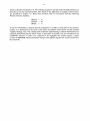
neutronics grid as follows:
CULEAK(I,J)
=
L
(FMJX(I,J,IG) - FMJX(I+1,J,IG)
+ FMJY(I,J,IG) - FMJY(I,J+1,IG»
* ADFLUX(I,J,IG)
for IG
=
1,IGM
The sum over the leakage values of all meshes is calculated simultaneously and stored in
variable CURINT as
CURINT
=
L
CULEAK(I,J)
for I = 1,IT, J = 1,JT
It has to be noted that horizontal and vertical neutron flows are only calculated if a particle
balance table is also required. In order to cause the preparation of this table together with the
neutron flows, variable IBALP = 3 has to be specified in LINKM and transferred to the
TWODANT SOLVER module via SOLINP file.
As already mentioned before in the same chapter, in the TWODANT SOLVER module of
SIMDANT the coarse mesh grid is identical to the fine mesh grid.
33
5.6
General program flow using LINKM as interface between
SIMMER and the TWODANT SOLVER module
The general program flow for the interaction between SIMMER and the TWODANT
SOLVER module is steered in the SIMMER main pro gram SIIIPR. Whenever a neutron flux
calculation has to be performed, subroutine GRIND is caIled by SIIIPR. The parameters for
directing the flux calculations are set as foIlows:
With the assumption that no constant adjoint flux distribution is requested as quasistatic
weight function (IWTF = 1) the calculation starts with the determination of the
stationary adjoint flux for later use as quasistatic weight function (IWTF = 0). (IWTF is
given in the SIMMER input.)
The parameters are set as ITH = 0 and IAD = I in SIIIPR before calling subroutine
GRIND. Subsequently, IAD = 0 is specified, inducing the stationary direct flux
calculation by a second caIl of GRIND.
The calculations of the stationary adjoint and direct fluxes, respectively, are omitted in
case of arestart run (RSTRUN = .TRUE.).
Then, with ITH
initiated.
= 1, IAD = 0 aseries of instationary direct
flux shape calculations is
In subroutine GRIND the actual flux calculation is initiated by a caIl of subroutine
TWODANT, the main routine of the TWODANT SOLVER module, dependent on the
parameters ITH and IAD. Before the caIl of subroutine TWODANT the parameter ILINK is
set = -1 and subroutine LINKM is caIled dependent on ILINK for preparing the interface files
ASGMAT, GEODST, MACRXS, ADJMAC, and SOLINP. AdditionaIly, for instationary
calculations the adjoint flux file adflux as weIl as the direct flux file rtflux are written using
the actual date and time in the file identification record and transmitting the values actuaIly
stored in the data areas for adjoint and direct fluxes, ADFLUX and CUFLUX, respectively. In
case of arestart run (RSTRUN = .TRUE.) only the direct flux file rtflux is written.
When having terminated a stationary or instationary direct flux calculation in subroutine
TWODANT, subroutine LINKM is caIled a second time, after having changed parameter
ILINK = 1, in this way only causing the calculation of the leakage values for the reactor
system needed later on for the reactivity determination.
34
6
Modifications in the original SIMMER routines
As described in more detail in chapter 10, the SIMMER code consisting of a large number of
subroutines, functions and COMMON areas comprised in the so-called HISTORIAN pro gram
library, is managed by the code maintenance system HISTORIAN which has been used as a
preprocessor from its very beginning.
HISTORIAN directives inc1uded in the HISTORIAN program library, the so-called master
file of the SIMMER code, allow the construction of different executables containing a large
variety of diverse options. In this way it is possible, for example, to build up specific
executables of SIMMER which are able to run on different computers containing either the
TWOTRAN-like solver part as used in the past or the TWODANT SOLVER module recently
inc1uded into the SIMMER code as weIl by starting from the same master file and activating
different directives specified in the HISTORIAN input file HINP.
The following six subroutines
OUTER
PCGNUC
OUTACC
INNET
FIXUP
REBAL
are no longer used to construct the TWODANT SOLVER module. Instead more than 300 new
subroutines and functions (HISTORIAN DECKs) and about 140 new COMDECKs have been
added. Nevertheless, the six TWOTRAN routines are still inc1uded in the master file so
allowing altematively the construction of an executable containing the TWOTRAN-like
solver part for comparison calculations.
It is almost impossible to describe explicitly every alteration, omission or introduction of a
specific Fortran statement in these particular subroutines. It was decided, therefore, to store
for longterm purposes the working version of the ongoing SIMDANT development
(containing alterations until about end of 1997). This dataset contains all the alterations
identified by comment cards comprising the date of its inc1usion and the identification of the
responsible person and, moreover, in many cases an explanation for the purpose that lead to
the inc1usion, alteration or omission. In this chapter the description is restricted to a more
general explanation for the alterations.
35
6.1
Modifications in the main program SIIIPR
SIMMER calculations normally require large computing times if they are performed far
adequate models of actual safety related problems. Therefore, the restart option is applied in
many cases. Restart runs in SIMMER are frequently started by using the same input package
as was used for the original run by replacing only the first line containing the START
command by another first line containing the RESTART command being followed by the
number of the restart file to be used. This procedure is allowed in principle according to the
SIMMER description /6/. It should be noted that the restart file is overwritten by the sim05
input of the restart input file. The user, therefore, has to check carefully which variables (also
p-, T-, data arrays, etc.) he wants to overwrite. Special attention should be given to the
following six input data blocks. If at least one of it is present in the actual input file, SIMMER
takes its parameters from these blocks which could disturb a smooth and proper continuation
in a restarted run. These six input blocks are:
&NINI
&NISO
&XBND
&XCWD
&XRGN
&XSOS
An adequate continuation could only be guaranteed, if the parameters contained in the six data
blocks are taken from the values included in the restart dump file. This is assured, if data
blocks in question are omitted in the input f1le. Therefore, a pro gram part has been included
into SIIIPR in order to check which input blocks are contained in the input stream. If
necessary, the user is requested by a warning to check whether he really wants to introduce
the values from the input file actually contained in the subdirectory (in a UNIX environment).
Concerning unit numbers some changes had to be performed because some numbers formerly
used in SIMMER are used in TWODANT as weIl. Because of the complicated file handling
in TWODANT, the changes have been accomplished in SIMMER. Unit BFU = 10 for the
SIMBF file has been changed to BFU = 77; unit numbers VISFU = 31 and VISNU = 77 have
been changed to VISFU = 79 and VISNU =78, respectively.
A new file OUTDI has been introduced using unit number OUTDI = 80 in order to provide a
capability to write important messages concerning extraordinary program flow or the
occurence of unusual values for certain variables on a separate file. That important
information from the SIMMER code to the user could otherwise get lost and remain
undiscovered in the heap of ardinary SIMMER output on file SIM06 on unit OUTFU = 6.
File OUTDI is used in accordance with input variable EDTOPT(80) of input block &CNTL.
For EDTOPT(80) = 1 file OUTDI is used, far EDTOPT(80) = 0 the important messages are
written on file SIM06.
36
6.2
Adaptation of SIMMER subroutines for the inclusion of the
TWODANT SOLVER module
a) The most essential modification in subroutine GRIND
TWODANT instead of subroutine OUTER.
IS
a caIl for subroutine
In the past, OUTER was used to solve the extended neutron transport equation using the
TWOTRAN-like algorithrns in order to obtain the flux shape function for the stationary
adjoint and real problems and for the instationary real cases as weIl.
Subroutine TWODANT comprises those parts of the DANTSYS main program DRIVER
which are used for the organisation of storage locations and extemal file-units as weIl as
for the caIl of subroutine TIGF20, the driver program of the TWODANT SOLVER
module.
Subroutine TWODANT is caIled by subroutine GRIND for the calculation of the
stationary (value of variable ITH = 0) adjoint (IAD = 1) and real (IAD = 0) flux shape
function, respectively. Subsequently TWODANT is caIled to calculate the instationary
(ITH = 1) real (IAD) = 0) flux shape function for each time cycle.
Each caIl of subroutine TWODANT is preceded by a caIl of the interface subroutine
LINKM (ILINK) where the argument is set to ILINK = -1, so causing the preparation of
the interface files (see chapter 5) which are needed to run the TWODANT SOLVER
module. After the calculations of the real flux distributions as weIl in the stationary case
as in the instationary cases, LINKM (ILINK) is caIled a second time where the argument
now is set ILINK = 1, causing the calculation of the leakage values, needed to build up
the balance tables and the calculation of the reactivity values in SIMMER.
After the caIl of subroutine TWODANT the calculated adjoint or real scalar and angular
flux values are read from the TWODANT interface files atflux, rtflux and raflxm and
stored in the corresponding data arrays ADFLUX, CUFLUX, CHEDGE and CVEDGE,
respectively, for later use in the code. The angular flux is separated into the horizontal
part stored in CHEDGE and the vertical part store in CVEDGE, respectively'. After their
calculation the actual real flux values are saved on additional files, so that the real scalar
fluxes can be used as starting guess for the transient calculation. The relation of file
names and unit numbers is as foIlows:
Files prepared by TWODANT:
file name
atflux
rtflux
raflxm
unit name
IATFLI
IRTFLI
IRAFL
unit number
21
22
11
contents
adjoint flux
real flux
real angular flux
1 At the time being the option of printing the angular- and space-dependent adjoint fluxes has been disregarded
in SIMDANT; however, its activation would be trivial ifreally needed.
37
Files prepared by GRIND:
ATFLUX
RTFLUX
I
I
IATFLO
IRTFLO
adjoint flux
real flux guess
23
24
I
I
In subroutine GRIND alterations for the input of reactivity ramps have been provided in
order to get it in accordance with the input description /6/. Now external reactivity can be
input as reactivity and/or as ramp rate. To provide the feasibility to check the correctness
of the input ramps, the values are printed in tables in the ordinary SIMMER output on file
SIM06.
In predecessors of the actual SIMDANT version inconsistencies have sometimes
occurred in reaching the time limit parameter TWFIN exactly using the actually
calculated time steps. These inconsistencies could be removed by adding a very small
program part (partially extracted from rudiments offormer SIMMER packages).
In an extension of subroutine GRIND, the summary for negative flux fixups for the
adjoint case, calculated and put together in subroutine PRNTFX, is written on file VISNU
= 78 (along with other neutronics postprocessor data) for later use in evaluation and plot
programs by calling subroutine WPPNK on request by the user. (In this case the number
of neutron energy groups in the input package has to be set IGM < 0 and input variable
IOUTNI of input block &NVIS has to be set = 1 or = 3.)
The corresponding task for the stationary and all instationary real calculations is initiated
in subroutine PKDRIV by calling subroutine WPPN. In this subroutine the tables for
negative flux fixups are taken over from subroutine PRNTFX via COMMON area
XNFX. The values are put together and written on file VISNU =78 by calling subroutine
WPPNK.
(Files NISART, unit number VISNU = 78, and VISART, unit number VISFU = 79, are
prepared by the postprocessor system VISART, in use at FZK for several years.)
Affected routines:
GRIND
b)
LINKM PKDRIV
PRTNFX TIMSTP
WPPN
WPPNK
As described in more detail in chapter 7.2 the time-derivative of the scalar flux d<D/dt is
replaced by the corresponding time derivative of the angular flux d'PIdt. Therefore, in
subroutine PKDRIV the associated time derivatives, d'I'Idt, are treated in a completely
analogous manner for extrapolations and interpolations in time as that had been
previously applied to d<D/dt. Subroutine EXTRAP has to be called in subroutine PKDRIV
not only to extrapolate and interpolate the scalar fluxes to the current time of the accident
analysis but also the horizontal and vertical angular fluxes, respectively. At the end of the
procedure the previous values of the angular fluxes have to be replaced by the actual
ones.
As a consequence of using the time-derivatives calculated from angular fluxes, in
subroutine POWCAL additionally to the scalar fluxes the angular fluxes have to be power
normalized, too. After power normalization the actual angular fluxes are transferred into
the storage location for the previous angular fluxes.
38
In subroutine PKDRIV warnings are printed on the ordinary output file SIM06 and, if
requested by the user additionally on the special output file OUTDI for important
messages, if no reliable ramp rate could be expected in the actual calculations. This may
be possible in cases where the absolute value of the initial reactivity increment for the
initial flux shape time-step is less than the absolute value of reactivity residual, or if the
absolute value of the reactivity increment is less than the convergence accuracy or
comparable to the computer accuracy.
Affected routines:
PKDRIV
POWCAL
c) The TWODANT SOLVER module needs the macroscopic absorption cross-sections ABS
to be included into the principal neutronics data for the determination of the meshwise
neutron balance. Therefore, the COMMON /CELXS/ used to store the macroscopic cross
sections has been extended by the data area
CELABS(NEI J,NEIGM)
for storing the absorption cross-sections for all meshes of the neutronics grid and for all
energy groups
The macroscopic self-shielded absorption cross-sections are calculated in an extension of
subroutine SHLDXS and its associated subroutine CALCXS (dependent on the fact
whether the macroscopic cross-sections have to be calculated for isotopes or materials)
analogously to the macroscopic self-shielded fission and capture cross-sections according
to
CELABS (I J,GRP)
= L (DENISO(I J,M) . VF
. (XSISOcaptCM,GRP) . FFISOcapt(l J,M)
+ XSISOfis(M,GRP) . FFISOfis(1 J,M)))
where
DENISO(I J,M)
VF
is the number density of isotope M in mesh I J
is a factor for the approximate treatment of heterogeneity effects
for thermal neutron reactors. In case of fast neutron reactors: VF
=1.
XIS Ocapt(M,GRP),
XISOfis(M,GRP
are the microscopic capture and fission cross
respectively, for isotope M and energy group GRP
FFISOcapt(D,M),
FFISOfis(D,M)
are the capture and fission resonance self-shielding factors (ffactors), respectively, for isotope M in mesh I J for the energy
group being considered
Affected routines:
SHLDXS
CALCXS
sections,
39
Some errors occurred during extensive SIMDANT calculations which were unexplicable
at a first glance. The introduction of unsuitable input files
frequently led to those inconsistencies especially in restart runs.
Additional checks of the input parameters have been included
into subroutine CHKPAR. In case of errors the job is aborted at
early runtime accompanied with arequest to the user to check
the input parameters.
(Comment: It would be desirable to include even more consistency checks to guarantee
compatibility of redundant input data contained in the SIMMER inputstream.)
Affected routine:
CHKPAR
d) According to an implementation flaw in a preliminary SIMMER version, amistake
occurred in restart runs. As a consequence of using the time-derivatives calculated from
angular fluxes instead of the scalar fluxes, the angular fluxes have to be included into the
restart dump file too in order to assure a smooth and proper continuation of the restart
calculation.
Inclusion and retrieval of a data area into arestart dump file in SIMMER is a relatively
extended task. First of all the data area has to be declared as a named COMMON area.
An integer variable has to be added at the end of the COMMON area which is provided
to store the length of the data array. This COMMON area has to be introduced into the
subroutine INILEN where its length is determined by a call of subroutine LENG and
stored in the variable at the end of the data array. Additionally, the total length of all
COMMON areas provided for the inclusion into the restart dump file is calculated in
subroutine INILEN, too. The inclusion of the COMMON areas into the restart dump file
is prepared in subroutine WRDMP. Each COMMON area is transferred by a call of
subroutine WRUNF. In the same way the retrieval of COMMON areas is prepared in
subroutine RDDMP. Each COMMON area is transferred by a call of subroutine RDUNF.
Affected routines:
INILEN RDDMP
RDUNF
WRDMP
WRUNF
e) In the same way the
COMMON /MISC/ LPRINT,LSMISC
has been prepared for inclusion into the restart dump file in order to make the logical
variable LPRINT available in its original state in each program unit where it is used to
decide whether additional output is required on a separate output file for important
messages.
LPRINT is set according to the value of the input variable IGM for the number of neutron
energy groups as follows:
LPRINT = .TRUE.
LPRINT = .FALSE.
forIGM <0
forIGM > 0
40
Affected routines:
ADJLCM
INPROD
RDUNF
TINP24
CHKPAR
KEYWRD
SCMADD
TMONIT
DMPFLX
LCMADD
TFINAL
WPPN
GRIND
PRNTFX
TIGF20
WRDMP
HILYTE
PRNTIA
TINP21
WRUNF
INILEN
RDDMP
TINP22
41
7
Modifications in the TWODANT SOLVER routines
For the solution of SIMMER-relevant problems after the replacement of the TWOTRAN-like
routines by the independent TWODANT SOLVER module, the following 27 TWODANT
routines had to be modified as described and also listed in chapter 3:
CHEBY
DRIVER
MASWEPW
TESTGO
TINP24
CIFLSM
HYLITE
PRNTIA
TFINAL
TOUTER
DESTDA
KEYWRD
PRTNFX
TIGF20
TRANS 0
DIFFO
LCMADD
RDSOL
TINITA
DMPFLX
MACMIX
SCMADD
TINP21
DOUTER
MASWEP
SINNER
TINP22
In addition, the two completely new subroutines LINKM (fully described in chapter 5) and
CHIMOD had to be attached.
It is almost impossible to describe explicitly every alteration, omission or introduction of a
specific Fortran statement in these particular subroutines. It was decided, therefore, the
working version of the Fortran source program of the SIMDANT development (of the
ongoing development up to about end of 1997) to be stored far longterm purposes. This
dataset contains all alterations identified by comment cards usually comprising the date of its
inclusion and the identification of the responsible person and, moreover, in many cases the
explanation far the purpose that lead to the inclusion.
In this chapter the description of modifications is restricted to a more general explanation for
their insertion.
42
7.1
Subroutines TWODANT and TIGF20 as driver programs
for the TWODANT SOLVER module.
In order to initialize properly variables, data arrays, and COMMON areas for later use in the
TWODANT SOLVER module it tumed out to be the best solution to include the DANTSYS
main pro gram called PRO GRAM DRIVER. The name was changed into SUBROUTINE
TWODANT in order to make its call more obvious in the SIMMER-III SUBROUTINE
GRIND. The information used for initialization is either stored in BLOCK DATA units or has
to be provided by some auxiliary routines called by SUBROUTINE TWODANT, as for
example the actual date and time or the actual computer configuration.
As a consequence, some subroutines called in SUBROUTINE TWODANT had also to be
attached to the TWODANT SOLVER module in order to perform the data initialization,
making use of the contents of 6 BLOCK DATA units which had to be added, too. These
subroutines are contained in Table 1 and Table 2 of chapter 3.
Three COMDECKs COMECS, LNSINP, and TIA, all ofthem contained in Table 3 of chapter
3, were also introduced into SUBROUTINE TWODANT.
Within the independently running program system DANTSYS, PRO GRAM DRIVER
organizes the general flow according to the input data given. As SUBROUTINE TWODANT
in the framework of SIMMER-III is used only to initialize variables, data arrays and
COMMON areas and to call specifically SUB ROUTINE TIGF20 in order to perform the
calculations for the solution of the two-dimensional neutron transport equation, large program
parts in SUBROUTINE TWODANT could be ornitted. As the TWODANT SOLVER module
gets all the relevant information, suitably prepared by SUROUTINE LINKM, on five
interface files ASGMAT, GEODST, MACRXS, ADJMAC, and SOLINP, described in detail
in chapters 4 and 5, it is no longer necessary to retain the calls of those subroutines for input
handling, material rnixing and cross-section preparation and for preparing the edit output and
the call of the edit routines which are not needed in SIMMER applications.
Furthermore, it is important to drop the calls of those pro gram parts in SUBROUTINE
TWODANT which remove some special interface files by calling SUBROUTINE DSTROI;
especially the interface file SOLINP which was prepared by SUBROUTINE LINKM and will
be used in the TWODANT SOLVER module afterwards.
By calls of the corresponding subroutines SCMDFT, LCMDFT, SUNASG, SUNOFF,
SUNATX, MDOPC, and DOPOFF the storage extension is performed problem dependent
according to the values NFALSE and NSCM to be set appropriately in SUBROUTINE
TWODANT (see chapter 10).
SUBROUTINE TIGF20 is called by SUBROUTINE TWODANT and organizes and controls
the course of the two-dimensional neutron flux calculation. Although the complicated scheme
of innerlsubouter/outer iterations is considered, supplemented by pure diffusion calculations,
TIGF20 could remain nearly unchanged. The COMDECKs COMECS and MISC, included in
Table 3 of chapter 3 and NEUFLGI and IPARAMI of the SIMMER-III code had to be added
in order to enable access to the unit numbers initialized for the TWODANT SOLVER module
and to the variable LPRINT indicating whether additional output should be prepared on the
43
standard output unit or not. A message is written on the output file if the interface file raflxm
containing the angular real flux is established, dependent on the value of LPRINT.
The variable GAMMA is saved as a result ofthe y-iteration for later use in SIMMER.
44
7.2
Adaptation of TWODANT routines for specific SIMMER
tasks
In the quasistatic approach an inhomogeneous (extemal-source) problem is treated as a
pseudo-eigenvalue problem, where a pseudo-eigenvalue parameter - usually denoted y characterizes the quality of the obtained solution. The standard TWODANT SOLVER
module only allows to deal with a standard eigenvalue problem, such as the real and adjoint
stationary cases, or an inhomogeneous source problem with specified external sources. The
conversion of a source problem (in SIMMER e.g. due to the delayed neutrons and their
precursors) to a pseudo-eigenvalue problem was a new feature which had to be implemented
in the TWODANT routines in a very careful manner. The associated modifications were
much more complicated than in the existing SIMMER version - based on the TWOTRAN
solution scheme - mainly caused by the diffusion synthetic acceleration (DSA) scheme. This
new and attractive feature improves considerably the convergence behavior but requires
particular attention to be attributed to the correlation between the transport and diffusion part
of the solution algorithms. In particular the inherent renormalizations of (pseudo-)
eigenvalues and associated fluxes had to be modified accordingly when converting the source
problem to a pseudo-eigenvalue problem.
A) Time derivative:
The time-derivative of the space- and angular-dependent shape function d'Pldt (with usually
small influence) is taken into account in an approximative manner in the previous SIMMER
versions up to version 2d and is still handled in this way in the actual SIMTRAN version, too:
(a)
Only the space dependent scalar flux d<D/dt is considered, i.e. the angular dependence
is neglected
(b)
The time-derivative of the scalar flux, d<l>/dt, is dealt with approximately during the
rebalancing procedure.
Since there doesn't exist such a rebalancing feature any longer in TWODANT, an alternative
method had to be found. Due to the claimed minor effect of this term, d'l'/dt, an approximate
treatment was still considered to be sufficient (being aware that the contribution of this term is
even neglected completely in some codes). In the new version, this additional term is
neglected in all but the last transport sweep. Therefore, the computational effort remains
almost unchanged and, furthermore, in this final transport sweep (which is inevitably needed
for other reasons explained below) it is not necessary at all to deal with transport-diffusion
correlations because in those circumstances the diffusion part is completely omitted. It should
be mentioned that, in contrast to the previous SIMMER version, in the current version the
rigorous angular dependent shape function is really considered. In the corresponding
SIMMER subroutines, the associated time derivatives, d'l'/dt, are treated in a completely
analogous manner (for interpolations and extrapolations in time) as that previously applied to
d<l>/dt. Originally one reason for using d<l>/dt instead of d'l'/dt was the increase of computer
storage requirements when applying the latter, rigorous option. Although this argument is still
valid, with currently available computer capacities there is no longer any need to adhere to the
decision of the past, to insist on reduced storage requirements and corresponding decreased
data transfer. (Admittedly the storage needed for the restart-files increases significantly.)
45
The restriction to the final transport sweep is - most probably - well justified by the usually
almost negligible influence of the d'P/dt term on the reactivity and on the flux- and powerdistributions of the system during a transient. In one example the associated influence on the
pseudo-eigenvalue Y= gamma ofthe quasi-static method was found to amount to about 3.10-8 •
In any case the mentioned final transport sweep is needed because in the TWODANT solution
procedure the angular fluxes will only be provided and stored upon performing such an
additional final transport sweep. These angular fluxes are needed for preparing the mesh-wise
neutron balance tables which in turn are aprerequisite for establishing the associated mesh
leakages. These leakages, together with the adjoint fluxes, are evaluated for determining the
corresponding contribution to the overall reactivity of the system and its reactivity variation
during a transient.
B) Negative flux fixups:
Being well-known, the standard diamond difference discretization scheme is affected by
negative fluxes frequently arising due to extrapolations in rather coarse meshes with
dimensions sometimes appreciably exceeding one average transport mean free path. This
might not always be a severe disaster: Lathrop's comment in the second paragraph of the
introduction in /121 should be recalled: "In many cases the negative fluxes, while annoying,
can be tolerated because they occur in regions in which fluxes are small and unimportant, but
in an increasing number of situations, negative fluxes interfere with the solution process." As
a potential remedy, negative flux fixup is applied for obtaining non-negative solutions for the
distributions of scalar and angular fluxes, although mesh refinement would be the more
suitable alternative but this could sometimes lead to a prohibitive increase of the
computational effort. Therefore, in all SIMMER versions existing up to now, an option could
be used that yields nonnegative scalar fluxes. However, as mentioned in the SIMMER Manual, even this modification cannot completely exclude negative angular fluxes at the
mesh edges (or surfaces). In fact, in a test case such negative values were really detected
when using the TWOTRAN-based SIMMER-III version 2d and adding the corresponding
diagnostic features. Considering that the angular fluxes are used for determining the mesh
leakages and, subsequently, the reactivity, even the application of such an improved
discretization scheme casts some slight doubts concerning the reliability of such a method for
some exceptional cases. Unfortunately, the user was not notified in the past about the
occurrence of such a situation (presumably because there was no easy way to avoid it when
using the former SIMMER versions).
C) Adaptive Weighted Diamond Differencing (AWDD)
Fortunately, there was an option available in the TWODANT SOLVER, too, that allowed the
application of the AWDD method in R -Z - geometry (/71 indicates the basic features for XYZgeometry). This option can be applied, too, in the current version of SIMMER (by specifying
the associated TWODANT input data WDAMP - see chapter 14 Appendix A Short
description of the AWDD scheme). The application of this option (as an alternative to the
standard solution scheme with fixups, i.e. setting negative fluxes to zero and recalculating the
other values) is appreciably facilitated by the existence of the fixup tables (obtained for 10M
< 0) which indicate the percentages of negative flux fixups in each energy group and for each
coarse mesh when using the standard solution scheme. The analysis of these tables (which
were slightly extended) provides very useful information (regarding space and energy
dependence) from which experienced users could obtain a deeper insight into the potential
46
significance and relevance of the monitored fixups with respect to the accuracy and reliability
of the associated solution.
The same tables could as well be used for monitoring negative angular fluxes when trying to
apply the AWDD scheme. Such negative values may still be encountered when the "tuning"
parameters specified in the input were not chosen suitably. The choice of appropriate values
still has to be done on a trial and error basis. However, it can be expected that experienced
users with sufficient knowledge in reactor neutronics will be able to deterrnine near-optimum
input values when applying the AWDD option.
The subroutines of the TWODANT SOLVER module which are affected from the adaptation
to SIMMER applications are;
TOUTER
MASWEP
DOUTER
MASWEPW
SINNER
MASWEPD
TFINAL
TESTGO
The detailed description of the extensive alterations, omissions or introductions of Fortran
statements may be found together with some explanations in a file which was used as
working version during the SIMDANT development and contains the FORTRAN source
program. This file is stored at FZKIINR for longterm access.
47
7.3
a)
Some minor modifications in several subroutines
For the calculation of the neutron source in DOUTER and TOUTER the delayed neutrons
and their precursors have to be taken into consideration. According to the original
SIMMER formalism, the neutron source is built by summing the two separate
components stemming from prompt and delayed neutrons, respectively. Even in the
stationary case the precursor concentrations DELAYC, are always determined
immediately after having obtained new neutron fluxes during the outer iterations.
Therefore, a few statements had to be added in DOUTER and TOUTER for calculating
the steady state precursors during the sub-outer (diffusion) and outer (transport)
iterations. An alternative possibility would have been to determine a converged flux
solution first - using a modified fission neutron spectrum, as described in the following and then, to determine the precursor concentrations, by using these fully converged
fluxes. (This simplification results from combining the equation for the precursor
concentrations with the equation for the neutron flux distribution for stationary
conditions, see e.g. Eqs. (V-29) and (V-31) in /10/.)
To maintain consistency with the solution scheme originally implemented in OUTER of
the existing SIMMER version we did not incorporate the simplification but kept the
inclusion of the DELAYC-component for the calculation of the real flux distribution for
the stationary case within the outer iteration process.
For the adjoint case, however, this procedure could simply be replaced by a modification
of the fission spectrum CHI as can easily be deduced from Eq. (V-61) of /10/. For this
purpose in subroutine MACMIX the newly written subroutine CHIMOD is called which
replaces the prompt fission spectrum by the total fission spectrum calculated in the
following way:
xtot,g (1,1)
(l - ß) xpr,g (1,1)
+
L ßk Xde1,k,g
fork= 1,IGD
with
fork = 1,IGD
where:
xtot,g(I,J)
ß
Xpr,g(I,J)
ßk
Xde1,k,g
IGD
= CHI total for neutron energy group g, in mesh I,J
= Betaeff
= CHI-prompt for neutron energy group g, in mesh I,J
= Beta of delayed neutron group k
= CHI-delayed of delayed neutron group k and neutron energy group g
= number of delayed neutron groups
Affected routines for this modification:
MACMIX
CHIMOD
b) A rather small correction had to be introduced in subroutine CHEBY in order to enable
Chebychev-accelerations to run properly in all cases that could occur.
48
Affected routine:
CHEBY
c) As discussed in chapter 5.5, the leakage values in SIMDANT have to be calculated in
subroutine LINKM for each mesh and, simultaneously, the sum over all meshes is
determined. To enable these leakage calculations, in subroutine CIFLSM the accumulated
horizontal and vertical neutron flows are multiplied by the corresponding geometric
values (see chapter 5.5) and stored in the data areas FMJX and FMJY, respectively. FMJX
and FMJY are transferred to LINKM as parts of the COMMON array narned ILEAKAG/.
Affected routines:
LINKM
CIFLSM
d) In subroutine RDSOL of the TWODANT SOLVER module relevant information which is
necessary for controlling the prograrn flow is read from interface file SOLINP.
Additionally introduced error checks assure the validity of some specific input data which
were collected in subroutine LINKM from SIMMER-own data areas. Other additional
error checks have been introduced in subroutine TOUTER in order to assure the correct
use of the TWODANT SOLVER module for SIMMER applications. In cases of errors or
inconsistencies the run is stopped and some relevant information is given in the output
protocol. The user is requested to check the consistency of the input data and to start
SIMMER again after having corrected the errors.
Affected routines:
RDSOL
TOUTER
e) The negative flux fixup monitor is printed in subroutine PRTNFX. The flux monitor gives
the percentage of possible negative flux fixups in each neutronics mesh. The fixups are
counted on each fine mesh cell face and accumulated and printed as neutronics mesh
quantities. Thus, if there should be more than 50% fixups, according to general experience
the quality of the pointwise flux in the neutronics mesh is suspect. If, based upon the
importance of an accurate solution for that group and coarse mesh, the user wishes to
increase the accuracy, it is recommended that the neutronics mesh cell size be reduced.
Whether refinement should be in the R- or Z-directions can be assessed by which faces
have shown the excessive fixups.
A lot of complementations to the original subroutine PRTNFX have been introduced and
mainly the strategy of the output of important information concerning curious prograrn
flow or other irregularities for the user has been extended. The value of the logical
variable lprint, set according to the value of the input variable IGM (number of energy
groups - see chapter 9.3 - use of IGM < 0) directs whether information is to be printed on
different output files or not. For more details see the file which was used as working
version during the SIMDANT development containing the FORTRAN source program.
49
Subroutine affected:
PRTNFX
f)
For routine applications the amount of standard output produced by TWODANT for
SIMMER calculations should be limited. On the other side, there have been provided
some feasibilities to extend the printing of output information for those cases where
strange or unclear results have to be expected.
Controlled by the contents of the logic variable lprint additional output is printed on the
standard output unit or on the screen as well. lprint is set according to the value of the
input variable 10M (the number of neutron energy groups) in the following way:
lprint
lprint
=
=
.TRUB.
.FALSE.
for
for
10M< 0
10M> 0
Another feasibility enables the output of essential information on a separate output file
which could be lost otherwise if hidden in the heap of the standard output file. In this case
the input variable EDTOPT(80) of NAMELIST block XCNTL has to be set > 0, so
causing special output to be printed on output file SIM80 with unit number OUTDI = 80.
Subroutines affected:
DMPFLX
SCMADD
HYLITE
KEYWRD
LCMADD
TINP21
TINP22
TINP24
PRNTIA
-
(
50
8
Adaptive Weighted Diamond Differencing (AWDD)
The Adaptive Weighted Diamond Differencing (AWDD) method can be used in TWODANT
to avoid negative angular fluxes at mesh edges. This method replaces the former SIMMER-lJI
input parameter NIOPT(30), POSDIF. The standard discretization method used in
TWODANT corresponds to conventional diamond differencing (DD) with negative flux
fixup. It is, therefore, equivalent to the former SIMMER-llI input parameter NIOPT(31),
FIXUP, i.e. AWDD OFF in TWODANT corresponds to FIXUP ON in TWOTRAN.
The user should be aware that the former input options NIOPT(30) and NIOPT(31) have no
longer any influence when running TWODANT; however, the corresponding output list
produced by SIMMER still reflects the choice of the options specified in the input.
In addition to the standard fixup procedure (i.e. setting to zero negative angular fluxes and
resolving the balance equation again under this condition to maintain the particle balance),
there two different AWDD methods are available, described in Appendix A, which, when
applied in a suitable manner, can avoid negative fluxes as well, They are based upon a
weighted diamond approximation for the spatial discretization (or even including the angular
discretization), which will give positive angular fluxes at mesh edges using a predictor
corrector method to determine the appropriate weights.
The application of the AWDD-method can be chosen by specifying according parameters,
WDAMPA and WDAMPR described in Appendix A, which have to be input in the new
NAMELIST block &NFIX of the SIMMER input file.
However, one important difference to the previously applied POSDIF = ON scheme should be
mentioned: in the AWDD scheme up to now the user has to find out -by trial and error- the
most suitable values leading to acceptable weight parameters and this can practically be done
only for the stationary cases (adjoint and real) but the parameters cannot be considered as the
most suitable choice for all core configurations that have to be analyzed during a reactor
transient. In the former POSDIF = ON scheme the appropriate weights were determined on
the basis of an approximate criterion which usually yielded positive fluxes except in a few
extraordinary circumstances.
Those users adhering to the combination of the options NIOPT(30) = 0 and NIOPT(31) = 0 in
previous SIMMER versions, i.e. POSDIF = OFF and FIXUP = OFF, will find in Appendix A
a possibility how to run TWODANT in the equivalent manner using AWDD.
For the sake of completeness, a concluding comment may be adequate: according to past
experience the POSDIF = ON option was, in general, more robust than the FIXUP = ON
option. Most probably this was the essential reason for the preference of the former, superior
option in contrast to the latter, occasionally inferior option. However, it is worthwhile to
mention that the negative flux-fixup scheme as implemented in TWODANT is more refined
than that one of the predecessor version based on TWOTRAN. Therefore, the reluctance to
apply the negative-flux-fixup option which was most probably justified in the past, should
now be abandoned, having available the extremely reliable and fairly robust TWODANT
package.
51
But in order to avoid any misinterpretation, it should be emphasized, that a too coarse mesh
grid could cause negative-flux-fixups in regions where a correct flux distribution would be
needed for a reliable neutronics behavior during the transient. Thus, a careful investigation of
the fixup tables is highly recommended. (The contents of the fixup tables may be included in
a special neutronics postprocessor data file named NISART from which the data may be taken
over into the TECPLOT system /17/ for visualisation. The NISART-file is written if the
NAMELIST block &NVIS is specified in the SIMMER-III input and it is set IOUTNI = 1 as
the only input value.) If the accuracy of the neutron fluxes in an important part of the energyspace phase-space becomes questionable it would be good practice to adequately refine the
grid and to check whether the essential results exhibit significant changes.
52
9 Input
9.1
Check of some values used in the PARAMETER statements
ofSIMMER
As mentioned in chapter 10 some values given in the PARAMETER statements of the
SIMMER code have to match exactly those values given in the input stream of the current run
in input file sim05. Some of those values affected by this instruction are listed in chapter 10.
When starting a SIMMER run this correspondence has to be assured; in case of disagreement
a new executable has to be established as also described in chapter 10.
9.2
New NAMELIST blocks &NFIX and &NVIS
By replacing the TWOTRAN-like solver part by the TWODANT SOLVER module the
general strategy was pursued, not to change the SIMMER input. This strategy could be
applied with only two exceptions. Using the POSDIF ON option in TWOTRAN the
parameters necessary for applying the adapted weighted diamond difference discretization
scheme (AWDD) are calculated code-intemally whereas these parameters have to be given as
input values in TWODANT. Thus a new NAMELIST block named &NFIX had to be
introduced in which two arrays for AWDD parameters can be specified. Array WDAMPA is
used for adjoint and WDAMPR for direct (real) calculations, respectively. In cases where the
&NFIX block is omitted in the input stream, both arrays WDAMPA and WDAMPR are set
equal to zero code-intemally by default. The calculations performed in this way correspond to
those applying the usual standard diamond difference (DD) discretization scheme with
negative flux fixup.
The new NAMELIST block &NFIX is used to activate the adaptive weighted diamond
difference (AWDD) discretization scheme and replaces the former input variables for
specifying POSDIF ON/OFF and FIXUP ON/OFF. The variables NIOPT(30) and NIOPT(31)
contained in the &NCNTL NAMELIST block are no longer used in the new code. In order to
avoid possible confusion in the interpretation of the output listing, it should be mentioned that
when specifying NIOPT(30) = 0, and NIOPT(31) = 0 the user will find in the SIMMER
printout: POSDIF = OFF and FIXUP = OFF. However, when using TWODANT without
WDAMP-input, the standard negative-flux-fixup algorithm is applied in TWODANT.
The following table shows the corresponding options:
SIMMER / TWOTRAN
POSDIFON
FIXUP ON (POSDIF OFF)
SIMMER / TWODANT
AWDDON
AWDDOFF
The values for the AWDD parameters have to be specified within NAMELIST block &NFIX
in the following way:
WDAMPA(NG), NG = l,IGM
WDAMPR(NG), NG = 1,IGM
53
where the index NG denotes the corresponding neutron energy group. The index starts with
NG = 1 for the group of highest neutron energy and ends with NG = IGM for the group of
lowest neutron energy as well for adjoint as for direct (real) calculations. For energy groups
NG with WDAMPA(NG) = 0 or WDAMPR(NG) = 0 no value has to be specified. The
meaning and consequences of inputting WDAMPAlWDAMPR < 0.0 is explained in
Appendix A.
The parameters WDTHRSA and WDTHRSHR also necessary for the AWDD scheme are set
= 1.0 code-internally for WDAMPAlWDAMPR .NE. 0.0. Otherwise they are also set =0.0
The NAMELIST block &NVIS has to be specified if the neutronics postprocessor file
NISART, containing among other things the data for the fixup tables, should be written for
later evaluation. In this case
IOUTNI = 1
has to be specified as the only value in the NAMELIST block &NVIS.
9.3
Use ofIGM < 0
The amount of output produced by TWODANT in the SIMMER environment should be
limited for routine applications. However, for non-standard cases, e.g. when dealing with a
new core design for the first time or when observing strange or unexpected results of the
neutronics calculations or when trying to determine suitable values of the damping parameters
(WDAMPA, WDAMPR) for the adjoint and real stationary case, it is most desirable to be
able to have a closer look into the details usually provided in the conventional TWODANT
output. Inclusion of this output in the normal SIMMER output file, SIM06, can be achieved
by setting the number of neutron energy groups, IGM, negative in the SIMMER input stream.
This is a rather new option. Additional information about the TWODANT run, e.g. storage
allocation, print of fixup tables, also a sketch showing the core layout, the dimensions and the
material distribution of the neutronics mesh, etc. can also be obtained by setting IGM < O. As
mentioned before, particular attention should be paid to excessive flux fixups in the DD
scheme and to negative fluxes in the AWDD scheme monitored in these fixup tables.
9.4
Separate output for important messages
Another option has been added to SIMMER. In cases where important messages should not
perish in the enormous quantity of the SIMMER output, variable EDTOPT(80) in
NAMELIST block XCNTL has to be specified as > O. Messages describing deviations of the
normal pro gram flow or unusual situations during the run are then written additionally on the
separate file named SIM80 with unit number OUTDI = 80.
54
10
Application of HISTORIAN for the preparation of new
executables for SIMMER calculations
The SIMMER code consisting of a large number of subroutines, functions and
COMMON areas is managed by the code maintenance system HISTORIAN /9/ which
has been used as a preprocessor from its very beginning. At FZK, HISTORIAN is now
used in its clone HISTORIANNE as received from Japan Nuclear Cycle Development
Institute (JNC) of May 1995. HISTORIAN-directives included in the HISTORIAN
program library, the so-called master file of the SIMMER code, allow the construction
of different executables containing a large variety of diverse options. (In this way it is
possible, for example, to build up specific executables of SIMMER which are able to
run on different computers containing either the TWOTRAN-like solver part as used in
the past or the TWODANT SOLVER module recently included into the SIMMER code
as well by starting from the same master file and activating different directives.)
Alterations, extensions and additional directives are introduced into the code, dependent
on the HISTORIAN input file HINP and on those directives already being included in
the SIMMER program library. The basis for all management operations with
HISTORIAN is the master file for the actual version of SIMMER called OLDLIB,
containing all subroutines, functions and COMMON areas that belong to the code as
HISTORIAN DECKs.
For the generation of new SIMMER executables including the TWODANT SOLVER
module, the actual starting point as master file is SIMMER-III in its version 2e as
distributed by JNC on June 1998. Since January 1999 this master file is replaced by
version 2f distributed by JNC. This master file may be completed by a number of
correction sets in order to correct detected errors or to extend the SIMMER code by new
program options. HISTORIAN is called as a preprocessor in order to introduce all
modifications to the master file given in the input data set HINP and to define options
either in the master file itself or also contained in the input file HINP. As a result,
HISTORIAN can produce a Fortran source file named COMPILE.
These different tasks,
attaching the master file to the actual directory,
causing HISTORIAN to introduce properly all alterations into the master file,
determining the actual date and time to mark the new version of the executable
are carried out in a shellscript named histor. The actual version of histor is included in
the Appendix B.
The following description of another shellscript and of four C-routines explains in
which way the generation of new executables is performed at FZK considering a UNIX
environment as installed on RS6000.
A second shellscript named siminst
splits the Fortran source file COMPILE into different data files named namef,
containing all Fortran subroutines and functions where name designates their
55
different names and stores them into a special subdirectory provided for this
purpose
constructs a Makefile and adds it to the subdirectory mentioned before.
The actual version of siminst is also included in the Appendix B.
The Makefile can be called afterwards using the instruction make in order to cause
the opening of a library for the inclusion of all object modules
the various calls of the compiler for all subroutines and functions
the linking of the object modules to the executable and to store it in the same
subdirectory as an additional file. (Its name is created as the name of the
subdirectory followed by .x)
the comparison of the creation date and time of the executable with those of the
creation or last modification of the different subroutines and functions. Only those
subroutines and functions are marked for compilation that have been changed after
the creation of the executable. (This means, if only small program modifications
have to be performed after the creation of the executable, it is not necessary to use
the whole extensive and cumbersome procedure of writing correction sets and
HISTORIAN input files HINP, introducing it by HISTORlAN into the master file
and thus creating a new COMPll...E file. Those small modifications can be
performed in the Fortran source programs name.f and a corrected executable can
be produced easily and rather quickly by a new call of the Makefile by using the
instruction make again. )
The Makefile may be extended by introducing other compiler calls or by adding or
changing the compiler options. It has to be noticed that all alterations in the Makefile
have to be done by using an editor which preserves preset tabulators, e.g. vi.
Before calling the Makefile, four program parts have to be added as object modules by
including them into the corresponding library to those object modules created by
compiling the Fortran source routines. These four object modules are:
morec.o
jobnam.o
macnam.o
scopy.o
The purpose of these program parts is:
morec:
The allocation of arrays in TWODANT is not done via variables that are defined in
PARAMETER statements but dynamically and, therefore, problem dependent. There
exists a C-source program morec.c which is system-dependent and arranges the
56
dynamical storage allocation of all arrays used in the TWODANT code. morec.c in its
RS6000 version is given in the Appendix.
Further information about the use and handling of this routine may be found
comments of subroutine TWODANT.
In
jobnam:
is used to provide the user' s identification of the current calculation and to store it for
registration in the output protocol and in all VISART files. jobnam.c in its RS6000
version is also given in the Appendix.
macnam:
is used to provide the name and classification of the computer of the current run and to
store it for registration in the output protocol and in all VISART files. macnam.c in its
RS6000 version is also given in the Appendix.
scopy:
is a utility program to be called by jobnam and macnam. scopy.C in its RS6000 version
is also given in the Appendix.
Because of different array-handling or allocation in SIMMER and TWODANT,
respectively, the dimensions of several data arrays, dependent on the number of meshes
in each direction, the number of neutron energy groups, or the Sworder etc. specified in
the PARAMETER statements have to match exactly those of the values given in the
input stream of the current run. If the values in the PARAMETER statements do not
agree precisely with those given in the actual run, arrays may overlap. In cases like that,
the calculated results are completely meaningless or show the "nonsense value" NaNQ.
As a consequence, for each calculational model that differs at least in one value from
those figures specified in the PARAMETER statements of actually used executables, a
new executable has to be compiled whose dimensions match exactly the respective
values given in the input stream. The correspondence of the values is shown in the
following table:
input value
dimension in the code
explanation
IB
JB
IGM
IT
JT
IGD
ISNT
IBM
JBM
NEIGM
NEI
NEU
NEIGD
NEISN
number of radial fluid-dynamics mesh cells
number ofaxial fluid-dynamics mesh cells
number of neutron energy groups
total number of neutronics radial mesh cells
total number of neutronics axial mesh cells
number of delayed neutron precursor groups
SN - order
57
The adjustment has to be performed as part of the HISTORIAN input file
following way:
In
the
*IDENT MYDIM
*DDIMEN.3
* IBM=IB, JBM=JB
*DNDIMEN.5
* NEI =IT, NEJ = JT
*DNDIMEN.6
* , NEIGM =IGM, NEIGD = IGD, NEISN = ISNT, NEINV = 16, NERXS = 6
The indented lines are parts of PARAMETER statements in COMMON DECKs which
overwrite the original statements in the code, thus adjusting the DIM:ENSIONs in the
SIM:MER code. (Therefore, 5 blanks have to be written in order to place the "*"-sign
into column 6.) IB, JB, IT, JT, IGM, and IGD have to be the same integer constants as
given in the SIM:MER input stream. For NEISN the absolute value of ISNT is to be set.
Some values are used in the SIM:MER code as maximum values for dimensioning
several data arrays; for example MNMS = 5000 or MNIM:S = 2000 as default values.
The exact values are calculated code-intemally, summarizing the lengths of a lot of data
arrays. For the calculations of "big runs" these dimensions may be too small and will
have to be enlarged. In those cases the SIM:MER run is stopped at the very beginning
and the actual values needed can be taken from error messages (for example the
constants 11 and 12, as shown in the following relation) to be adjusted in the following
way:
*DDIMEN.4
* ,MNMS =11
*DDIMEN.7
* , MNS = IBMP2*JBMP2, MREG
=50, MAXTP = 15, MNIMS =12
(IBMP2 and JBMP2 have been calculated code-intemally
statement.)
In
the PARAMETER
The preparation of a new executable as it is performed at the moment at FZK is shortly
demonstrated by means of an example:
(The description given rather detailed in the following should enable experienced
SIM:MER users to generate their own executable without appreciable assistance by a
local expert code administrator or even by an extemal "guru".)
An executable has to be compiled with adjusted dimensions for the following input
values by 7 steps:
IB = 17; JB = 54; IGM = 9; IT = 96; JT = 104; IGD = 6; ISNT = 4
It is known from former calculations that the dimensions MNMS = 5600 and MNIM:S
2500 are sufficient.
=
58
Step 1:
A new directory has to be established named e.g. histor96x104
Preparation of the HISTORIAN input file HINP (assumed: only the adjustment to
the input values is performed and no additional alterations have to be prepared in
the new executable).
*HISTOR(P,C)
*READ versio.tmp
*IDENT dummy
*IDENT MYDIM
*DDIMEN.3
* IBM = 17, JBM = 54
*DIMEN.4
* ,MNMS = 5600
*DIMEN.7
* ,MNS = IBMP2*JBMP2, MREG =50, MAXTP = 15, MNIMS =2500
*DNDIMEN.5
* NEI = 96, NEJ = 104
*DNDIMEN.6
* ,NEIGM = 9, NEIGD = 6, NEISNN = 4, NEINV = 16, NERXS = 6
Note: The identifier for the Fortran statement to be replaced in the HISTORIAN
pro gram library has to be specified very carefully. The correct identifier
could be found from a HISTORIAN source listing. Sometimes the
statement under consideration is given there several times with different
identifiers, distinguished by HISTORIAN directives.
STEP2:
Call the shellscript histor m the new directory histor96x104 by usmg the
instruction
histor
This causes the attachment of the HISTORIAN program library and renames it to
OLDLIB. The COMPILE file consisting of Fortran subroutines and functions is
then produced.
Step 3:
A new subdirectory (named for example: sunday) is to be established in
histor96x104. In this new subdirectory sunday the COMPILE file is to be
attached, for example by means of the instruction
Zn -sJ..ICOMPILE.
The instruction
siminst
causes the decomposition of the COMPILE file into the files name.j, containing
the separated Fortran subroutines and functions and the preparation of the
Makefile and adding it as file in the subdirectory.
59
(It is good practice to delete now the COMPILE file in subdirectory sunday as
well as in the directory histor96x104 in order to clear storage arrays.)
Step 4:
Now the new Makefile may be changed (by using e.g. the vi-editor) in order e.g. to
add/change new compiler options.
Step 5:
The four object modules, mentioned before, have to be attached by inclusion into
the library libsunday.a using the following instructions:
ar
ar
ar
ar
q
q
q
q
libsunday.a
libsunday.a
libsunday.a
libsunday.a
-object_directory/morec.o
-object_directory/jobnam.o
-object_directory/macnam.o
-object_directory/sscopy.o
Step 6:
Some values for the provision of the storage space in TWODANT have to be
adjusted by changing the default values "by hand" in subroutine twodant.f in
subdirectory sunday:
Increasing of (actual values depending e.g. on number of energy groups, Sworder,
number of meshes etc.)
NFALSE
NSCM
=400 000
to NFALSE
= 200 000 to NSCM
=2 000 000
and
= 2 010 000
and removing the statements
IF (NSCM .GE. NFALSE)
IF (NFALSE .LE. 2*NSCM)
NSCM = NFALSE / 2
NSCM = NFALSE / 2
In subroutine linkm.f one value has to be increased from
DMAT = 1 000 to DMAT = 10000
In which way DMAT has to be specified correctly and particularly how to proceed
if DMAT increases the value of DMAT = 10 000 is described in chapter 5.1.
Step 7:
Theinstruction
make
in subdirectory sunday causes the various calls of the compiler for all subroutines
and functions, the inclusion of the object modules into the library libsunday.a and
60
the preparation of the new executable with the name sunday.x in subdirectory
sunday.
If the run stops immediately after having started this new executable showing the error
message "NO CORE", it is sufficient to restart the compilation of a corrected executable
at step 6 of the example given above. The required values for NFALSE and NSCM,
respectively, may now be taken from the TWODANT protocol and used for the
modification in subroutine twodant.f
The repetition of the instruction
make
in step 7 will cause only the compilation of those subroutines which have been changed
since the last modification of the executable sunday.x. The corrected executable
automatically replaces the previous one in subdirectory sunday.
61
11
Test calculations
The new neutronics version of the SIMMER-III package has been applied to four
representative test problems, inc1uding static and transient cases, in order to validate and
verify the code. In this section, the brief descriptions of these test problems and the results are
reported. The test problems have first been calculated during the stay of one of us (E.H.) at
the Japan Nuclear Cycle Development Institute (JNC). The results were published
preliminarily in an internal report /16/. (At the time of performing these investigations the
WDAMPA-/ WDAMPR- < O. option, i.e. subroutine MASWEPD, was not yet available.)
11.1
FCA (Fast Critical Assembly)
Aseries of fuel slumping experiments has been performed in JAERI's FCA facility, of which
a cylindrical model of geometry and material arrangement is shown in Figure 3. Several
disrupted core configurations were simulated in the FBR test region with 14 % - Pu-enriched
fueL The test section was surrounded by the driver region with 29 % - U235-enriched fuel and
further blanket regions with natural or depleted U fueL
Upper
blanket
1.63
Nat. U
Driver
m
Fuel slumping
reqron
Lower
blanket
Nat. U
0.75 m
Figure 3: R-Z model ofFCA VIII-2 experiments.
Radial
blanket
62
In a central part of the test region (3 by 3 drawers of 5.5cm x 5.5cm each), the fuel
distribution was varied from a reference uniform distribution (AO) to three levels of
compacted configurations (Al, A2, and A3) and to a fuel dispersed configuration (S). The
patterns of fuel re-configurations are depicted in Figure 4, where a dark hatched region
represents compacted fuel having twice as dense fuel as the reference fuel density simulating
an intact eore. Fuel slumping into a compact configuration, from AO to A3, makes the axial
flux distribution peaky and this increases the fission rate in the dense fuel region, causing a
positive reactivity change. Beeause of a large void region developed above the fuel region, the
reactivity change must be evaluated by suitably treating negative reactivity effects due to
increased neutron leakage. This means the use of neutron transport theory is inevitable in
simulating the experiments. Although the seales of fuel re-distribution were only limited in
the FCA experiments, reactivity changes from the reference configuration were measured
sufficiently aceurate.
Z (cm)
81.28
Axial blanket (Na voided)
45.72
Normal core (Na voided)
30.48
Fuel compacted
15.24
Void (spacer)
0.00
-15.24
-30.48
-45.72
-81.28
AO
A1
A2
A3
s
Figure 4: Fuel relocation pattern in FCA VIII-2 experiments
Two series of test ealculations were done using different options with SIMMERITWOTRAN
and SIMMERITWODANT. The first table shows the result with POSDIF ON and the
SIMMERITWODANT corresponding option AWDD ON, the second FIXUP ON and AWDD
OFF. The ealculations were performed with SIMMER-III, version 2d using ISOTXS- /
BRKOXS-files prepared for 9 energy groups and 11 isotopes. The anisotropie scattering was
approximated based on the Bell-Hansen-Sandmeier /13/ prescription (P1APRX). The Sw
order was specified to N = 4.
63
POSDIFON
AWDDON
SIMMERJTWOTRAN
SIMMERJTWODANT
adjoint
real
1.00702616
1.00574626
4.8298E-4
1.00751559
1.00623686
4.8477E-4
1.007354450
1.1289E-3
1.00816797
1.00689455
1.1339E-3
1.00841946
1.007556997
l.3283E-3
1.00836616
1.00709942
1.3360E-3
1.006592140
1.005721157
-4.832IE-4
1.00654697
1.00525523
-4.8567E-4
adjoint
real
AO
1.007070811
1.006210146
Al
1.007560225
1.006699311
A2
1.008212480
A3
S
p
p
AWDDOFF
FIXUPON
SIMMERJTWODANT
SIMMERJTWOTRAN
adjoint
real
1.00707174
1.00648544
4.8087E-4
1.00756115
1.00697378
4.8183E-4
1.007864715
1.1233E-4
1.00821340
1.00762738
1.1260E-4
1.008412091
1.008064707
l.3201E-3
1.00841186
1.00782858
l.324IE-4
1.006593275
1.006237366
-4.8138E-4
1.00659306
1.00599712
-4.8228E-4
adjoint
real
AO
1.007071968
1.006725006
Al
1.007561369
1.007212599
A2
1.008213624
A3
S
p
p
k'-k A O
P= k'k
AO
k AO = k eff (AO real ) ,
k eff (a)
k'=k eff (a),
= k eff (Al real ), k eff (A2 real ) , k eff (A3 real ) , k eff (Sreal)'
respectively
Effective multiplication factors calculated for individual configurations were converted into
reactivity changes from the reference configuration (AO) and compared with experimental
measurements in Figure 5. The predicted reactivity change agreed fairly well with the
experiments with deviations in CIE of less than 20 % . The TWODANT module is judged to
be implemented into SIMMER-III correctly since the results of SIMMER-III using
TWOTRAN and TWODANT modules agree almost completely as shown in this Figure. The
effect of negative flux fixing up on the relative reactivity change seems to be negligible in this
case although the maximum percentage of the fixing up operation in the AWDD-OFF case
was around 20 %.
64
For TWODANT the same calculational model was used as was originally specified for
TWOTRAN. For these restricted investigations no refinement of the calculational model such
as increasing the SN order or reducing the mesh sizes, was considered.
Cautious remark:
The fairly good agreement between the POSDIF ON and POSDIF OFF( = FIXUP ON)
results, although being rather satisfactory does not necessarily mean that für that reason
both results can be considered as reasonably reliable. This conclusion would only be
justified if
(a) either the inspection of the fixup tables gives no indication of significant fixup
percentages for important regions of the energy-space phase space, or
(b) a refinement of the spatial and angular mesh grid confirmes the results obtained
with the coarser grid.
Even the fairly good agreement between the SIMTRAN and SIMDANT results cannot
be taken as a proof that the results can be considered as sufficiently accurate; primarily
it only means that both results are affected by roughly the same uncertainty. The
dominant feature is that the discretization error (although usually being sufficiently
small) is about the same in both solution algorithms.
15
10
5
o
I --Ar- TI',IOTRAN ~'
-5
~~
Tt',JODAA1"1
•.~ . . T/110DANT
yPOSDlF on I AWDD on
}}~OSDIF off / AWDD off
I
AC)
Al
A2
AJ
Figure 5: Predicted reactivity change by TWOTRAN and TWODANT
module
s
65
11.2
SRA (Static Reactor Analyses)
Parametrie cases are set up to investigate the reactivity change due to the hypothetical onedimensional compaction in the core of a large scale LMFBR (see Figure 6). In the compacted
configuration, an upper blanket region lies above the empty space produced by the
compaction in the core. This problem is a good example for demonstrating the superiority of
the new neutronics version based on the TWODANT code, because the former neutronics
package in SIMMER-III based on TWOTRAN initially failed to converge for the compacted
configuration.
(In order to describe the situation in more detail: initially, calculations performed with
TWOTRAN didn't converge at all; subsequent calculations performed at FZKIINR did
converge indeed, mainly as a result of using - instead of the default option NIOPT(2) = 0 NIOPT(2) = 4, the recommended option for the modified incomplete lower and upper
decomposition bi-conjugate gradient scheme for the preconditioned conjugate gradient
method for the rebalance equation matrix solver; but the results were still not reliable.)
Blanket
Void
Blanket
Figure 6: R-Z model of SRA (Static Reactor Analysis)
Two series of test calculations were done for the SRA case, too; the first one by using the
options POSDIF ON and AWDD ON, respectively, the second one using FIXUP ON and
66
AWDD OFF, respectively. The calculations were perfonned with SIMMER-ill, version 2d
using ISOTXS- / BRKOXS- files prepared by the neutronics preprocessor MXS /14/ for 9
energy groups and 5 materials. The Sworder was specified to N = 4.
compact
uniform
compact
uniform
POSDIFON
AWDDON
SIMMER / TWOTRAN
real
adjoint
0.97725826*)
0.98338562*)
0.98452505
0.98453313
SIMMER / TWODANT
adjoint
real
1.04216938
1.04190530
0.98448339
0.98426495
FIXUPON
AWDDOFF
SIMMER / TWOTRAN
real
adjoint
0.97700906*)
0.98342664*)
0.98451724
0.98453422
SIMMER / TWODANT
adjoint
real
1.04235340
1.04236921
0.98453418
0.98452736
*) see explanation given at the beginning of this chapter.
The new neutronics module based on TWODANT converged successfully for the compacted
configuration in this test problem whereas the fonner TWOTRAN module failed as well in
the FIXUP ON case as in the POSDIF ON case. These results verified the robustness and
superiority of TWODANT over TWOTRAN. The effect of the fixing up operation of negative
fluxes is apparent from the difference in absolute value of the effective multiplication factor.
However, the relative reactivity change between the compacted case and the uniform case is
not affected by the choice of various differencing schemes, i.e. the reactivity change due to
compaction is 0.05784185 in the AWDD-OFF case and 0.05764035 in the AWDD-ON case,
which can be considered as negligibly small. Again no efforts were devoted to investigations
using refined calculational models.
67
11.3
STN (Standard Test Problem for Neutronics)
This sample problem is intended to test the space- and energy-dependent neutron kinetics
model and its coupling with the fluid dynamics. The considered problem set-up is a fictitious
disrupted LMFR core of an intermediate size for simulating a short-time energetic recriticality
event with 12 by 16 meshes. In order to drive a very rapid reactivity insertion, a slug of
molten fissile fuel initially present at the bottom of the core axis is pushed toward the core
midplane with its initial velocity 100 m/s. The geometric model and initial conditions used for
this problem are shown in Figure 7. This reactor configuration and these initial conditions
minimize the effect of non-linear feedback processes between the material motion and reactor
kinetics. The resulting rapid positive reactivity insertion brings the core to prompt criticality.
The power excursion terminates in a short period of several milliseconds due to a negative
reactivity feedback mechanism of continued axial fuel motion in the core center beyond the
core midplane.
The reactivity and power transient are plotted in Figures 8 - 11 for both the TWOTRAN and
the TWODANT module, respectively. The discrepancy between the two codes is fairly small
and one can conclude that the implementation of the transient terms into the TWODANT
module and the coupling of SIMMER-III fluid dynamics and TWODANT have been
performed successfully. In addition, the effect of the fixing up procedure of negative flux is
larger than the effect of the difference between the neutronic modules. Both, TWOTRAN and
TWODANT, produce a little bit larger amplitude peak around 6ms with the fixing up
procedure than with the positive differencing scheme or AWDD scheme.
The calculations were performed with SIMMER-ill, Version 2d using ISOTXS- / BRKOXSfiles prepared by the neutronics preprocessor MXS /14/ for 7 energy groups and 5 materials.
The Sworder was specified to N =4.
68
i
16
~
14
mm
300
13
930
mm
CI)
E
0
0
4
~
i
350 mm
3
~
1
1
2
~
9
12
60.7 mm
~
856.2 mm
~
Figure 7: Configuration of the STN
(Standard Test Problem for Neutronics)
1172.2
mm
69
AMPLITUDE
C)
1-8 -
I
REACTIVITY
STN_SIMMER/TWOTRAN_FIXUPON
i
-
I
1.5
I
~
1
Li/ f~"\\,
..
/
\'
/
d
V/
:D
\
0.5
\\
--f
0
~\
~
/
<.
-
,
m
»
0
--
-0.5
I
I
-1
0.02
0.015
0.005
<
-<
--f
Figure 8: Plot of reactivity and power transient calculated by TWOTRAN
using FIXUP ON
e
AMPLITUDE
1-8 -
REACTIVITY
I
STN_SIMMER/TWODANT_AWDDoff
..............
~/
1.5
I
I
~
1
f~'\,
·7 /
/fJ
V .. /
/
/~)
\~
\
:D
•
\~ \
0.5
•
--f
0
~\'--El_____
<:
I
0.005
m
»
0
---I
0.015
<
-<
--f
-0.5
-
-1
0.02
Figure 9: Plot ofreactivity and power transient calculated by TWODANT
using AWDD OFF
70
'--'
AM PLiTUDE
I
- a - REACTIVITY
I
STN_SIMMER/TWOTRAN_POSDIFON
1.5
,
jL",,\
cz(/
........_/---_.)
jD
/
.>
1
'~~
\-
JJ
\
0.5
\\
(i
" ..
0
<,\
m
:l>
0
..,
..,<
-<
~.
e--.
-0.5
._....
,
-1
0.02
0.005
Figure 10: Plot of reactivity and power transient calculated by TWOTRAN
using POSDIF ON
~:
AM PLiTUDE
I
- a - REACTIVITY
I
STN_SIMMER/TWODANT_AWDDon
1.5
I
;21',
1
[2J// '~~
/
/
\-
JJ
;dJ \\
/J
\
0.5
•
0
~'\-,
~
'~
..
....
_
i
0.005
0.015
m
:l>
0
..,
<
~
-0.5
-1
0.02
Figure 11: Plot of reactivity and power transient calculated by TWODANT
using AWDD ON
71
11.4
TRA (Transient Reactor Analyses)
The final and integral test problem is the transient analysis of the early transition phase in a
core disruptive accident. The objective of this test problem is to verify the applicability of the
new code package and to find out whether plausible results can be obtained. The initial spatial
distribution of the material, temperature, and pressure is taken from the final state of the
initiating phase analysis by SAS4A using the interfacing code SAME-II. According to the
hypothetical assumption of a large diameter of the fuel particles, the one-dimensional fall
down of the relocated fuel causes a recriticality event around 1s which drives the subsequent
recriticality phase by a sloshing of molten core material.
The calculations were performed with SIMMER-ill, version 2d using ISOTXS- / BRKOXSfiles prepared for 7 energy groups and 21 isotopes. The Sworder was specified to N = 4.
_l
-~.~.~ AMPLITUDE I_~
10
REACTIVITY
TRA_SIMMER/TWOTRAN FIXUPon
4
,
10
3
10
2
,
D
..
50
r-t
........ .....__......
""
W
Cl
:::::>
I-
-50
~
«
10
1
~~'
1 0°
,
,
o
0.5
\
-150 ~
LJ\1 \
\r~fi,
..
1 0- 1
<
i/I
(/1
,
,
(~
1.5
rn
-1 00 ~
!I
/\
/\
::0
»
W
,
A
.....J
o,
o
-
-200
..
....,-!'
-250
2
Figure 12: Power and reactivity plot of TRA case calculated by
TWOTRAN using FIXUP ON
72
;::;
AMPLITUDE
1-8 -
REACTIVITY
I
TRA_SIMMER/TWODANT_AWDDoff
,
co
10
2
-------
~
------~
--- .-'\
U
, l;
[
--./
0
I
0
=>
-I
0..
~
...._---_....._.........._...__.........::;J •....... ................._....-..........
\
~
W
I-
5
10
!
1\
1
---~~/
«
1 0°
r-
:D
-5
i I
J\
)
k/
• I
-10
W~
\
\
~
m
:t>
o
-I
<
-I
-<
-1 5
f
~-
,
o
,
0.5
,
~IME
,
-20
1.5
2
Figure 13: Power and reactivity plot of TRA case calculated by
TWODANT using AWDD OFF
Please note: The seales used in Figures 12 and 13 are very different regarding amplitude as
weIl as reaetivity. The normalized amplitude peak at the first recriticality event
shows an increase by a factor of 40 (Figure 12) and by a factor of 20 (Figure 13).
It is nearly impossible to compare the trend of the reactivity values because of
the different scales as ranging from -250 [$] to +50 [$] in Figure 12 and from
-20 [$] to +5 [$] in Figure 13.
Therefore, the ealculated power and reactivity transient shown in Figure 13 is only
qualitatively similar to the result obtained when using the former SIMMER-III shown in
Figure 12 in the sense that the first recriticality event takes place around 1.1s and this drives
the second power burst by the sloshing pool. However, each recriticality event in the
ealculation by the TWODANT module is milder than for the TWOTRAN calculation. The
cause of this discrepancy is not yet fully understood at the moment and has to be investigated
in future studies.
When repeating at FZK the JNC runs leading to Figures 12 and 13 it was observed that the
results of the calculations for the TRA problem were affected by a deficiency namely the not
fully converged inner iterations (essentially due to the input value ITLMIN = 10). The used
SIMMER code version didn't monitor this fact in the output protoeol as it had done in the
former versions. Therefore, this failure, i.e. not achieving convergence, could not be identified
by straightforward analysis of the output file. After detection of this shortcoming at FZK, the
SIMTRAN calculations have been repeated at JNC and Figures 14 - 16 led to the following
conclusions:
73
I ---0' 0o
f
I
REACTIVITY
. ·.. _·.. _·····.. -··r···..
~
·······_..·T··
;
:
~ ~"
_ '•.•1:1..
....... ,
,,~
,
~
•• _
~
.
i
i
i
I
,
-510 tJ
I .. II ••••••
-2. 10'
"-"-
..
1
1000
.
!
~
w
,
,
..
:
l
:
100
.t •• _
!f
.1 10 1
~...
_
.
1.···_·····.. •.. •..••· '''T'' ........ ·•·..••••... ·r·.. . ··········..
:
:
:
, ..... .1:• ••• •••••••• ......
_
.
1
~
···_······1··_··_·_·····_···+
......._._._ ··1··_······
_. -............. .
--+
~....
",
,
r
.
.
=i
-
10
l--J,-""-~-'-....:....."-....................J................+.-...........~......._ _--...
o
0.5
:t>
:s
"'0
c
c
m
0.1
Z
, •.$
TIME
Figure 14: TWOTRAN POSDIF ON, FIXUP OFF
(inner iteration failure)
____ REACTIVITY
,
o lOG
.••••._
.•••.•••••;......
_ _l"--"""':',.....
!
"
~_._
i.~
~
-.5 10 Q
I-e-
1
•.•••._••1~ ••••.••••. -....
.
_
d_ •• 11. , ••• ,".'"
l
f
··i, •
~
~
:
1 · "..·. ·····t·
j
_, 10 1
:
............................ J...
i
t
~
..,
•
.
··-.
•
1000
_ •••• _ •••••
"'4.4.
110'.
"'!
·······_~·····
J. ,
4
~
~.
1
_._ - _.....
•
., .. _
100
-
1:
i
~4 ,
!.
.~~ ••• 4
•
.,
- •••••_""
10
.
0.1
z
0.5
:t>
:s
"'0
r
:
~.....
~....................l-~I.o-lo......... ...,.L_..- _..................................
o
10·
~
L..·....····_··....
;
_.,..
I
AMP LITUOE
!
•
__
. . . . . . . . . . . . . . . . . . . . . ~.~
-2 1<)1
u
TIME
Figure 15: TWOTRAN POSDIF ON, FIXUP OFF
(without inner iteration failure)
=i
c
e
m
74
I -M- REACllVITY ($)1
o 100 .......•.._....•../•...
·,
..
)
~
· ·· ·· · ·· t···..·
.
. . . . . _ -·..· ··t··
-
-s 10 a
..-.•• ,..-
~
>!::
>
i=
o
· .·
········1··.
-
!
~.-
i
l
~
1
i
-I 10'
«
-
_~_.~a
1000
I.r' .
.
_.-t-............................
._ _...•...•.•.
i
_.tl ._. ••·..
.
:
_- _
4
:
.
_......
..
100
~.jo.t ,.
;
t
!
I
....._...·········t··_·_···_····_·i·
. ·_ _·_ ·····.. ·1··.. ···_··__··.. ·.. ·'' '·· ,, ,................ _
.
\0
,
w
0:::
.1,5 10'
-2 10'
1
,
L....-....--'-.............I-...L.-.......-.......---l.-.4.-"""'-.........."'"-Jl---..--"'_...
o
0.5
'.5
0. 1
2
TIME ($)
Figure 16: TWOTRAN POSDIF OFF, FIXUP ON
(inner iteration failure)
Please note:The left-right position of the ordinate scales in Figs. 12-13 and Figs. 14-16,
respectively, has been changed.
When comparing Figures 14 and 15 it is evident that the transient behaviour of the SIMTRAN
results was affected substantially by the non-convergence of the inner iteration process.
Keeping in mind that Figure 16 shows results also obtained with a failure in the inner iteration
process for the POSDIF OFF, FIXUP ON case, the correspondence with the results in Figure
15 without inner iteration failure for the POSDIF ON, FIXUP OFF case is rather surprising.
But this fairly good agreement might be fortuitous and should not be considered as a
validation of the reliability of these results.
Comparing SIMTRAN and SIMDANT results in Figures 13 and 15 it is important to observe,
that now the scales are nearly comparable. Concerning the amplitude, the first recriticality
event is calculated by both code versions at 1.1 s showing an amplitude peak: of
approximately a factor of 30 (initially normalized to unity). The second recriticality event is
calculated by SIMTRAN exactly at 1.5 sand by SIMDANT at 1.45 s. The maximum
amplitude factor is calculated by SIMTRAN to 7 * 10 3 and could be estimated in the
SIMDANT calculation as to be not too different. (The scale ends in this case at 1 * 10 3.) The
reactivity curves show a similar trend up to the first recriticality event. Afterwards, the course
of the reactivity and amplitude curves is different. Whereas the SIMDANT results reach a
local minimum of approximately -0.5 $, SIMTRAN calculates a local minimum of -2 $. After
the second criticality event SIMDANT ends at a reactivity value of -18 $ at 2 s, whereas
75
SIMTRAN determines the reactivity curve with a rather steep gradient leading to values far
below -20 $.
The intercomparison verifies that SIMDANT can be applied for complicated transient
analyses and increases the confidence in the suitability of this upgraded tool. There are still
some nonnegligible discrepancies remaining between the results shown in Figures 13 and 15,
in particular in the peak: amplitude at about 1.5 sand the time behavior of the reactivity and
the amplitude afterwards. The origin of these differences is not clear presently. In particular it
would be premature to conclude that they will essentially be caused by the different
algorithms applied for the solution of the neutron transport equation.
It should be noted that in SIMMER highly transient dynamic processes with an interplay of
neutronics and fluiddynamics are simulated. Any change in the neutronics quantities
influences the fluid motion which - over a feedback loop - has an impact on the neutronics
quantities again. This behavior reflects the reality of dynamical systems. In addition some
types of threshold effects such as sudden pin failure, fission gas release, and fuel relocation
processes could exaggerate discrepancies of results. Therefore, differences as those observed
e.g. between Figure 13 and Figure 15 are not too unusual for results of codes dealing with
accident analyses and that is one of the reasons why with these code systems a band width of
results with a possible enclosing envelope should usually be calculated.
76
12
Experiences acquired from reactor analyses applying the
new neutronics module SIMDANT and Summary
In order to verify and validate the new treatment applied in SIMDANT, comparisons with the
SIMTRAN version were an inevitable task. After the completion of extensive comparison
calculations the general recommendation can be given:
Use the SIMDANT version containing the new neutronics treatment for
future SIMMER-III calculations.
Preliminary tests demonstrated that stationary and instationary problems could be run
successfully using SIMDANT when the corresponding TWODANT SOLVER module was
modified suitably to take into account the proper treatment of the delayed neutrons and their
precursors and the quasistatic solution method, as well.
In the quasistatic approach, an extemal-source problem is treated as a pseudo eigenvalue
problem, using the so-called y-iteration approach, as successfully demonstrated in the
SIMTRAN version of SIMMER-III. The standard TWODANT SOLVER module only allows
to deal with standard eigenvalue and standard source problems. The conversion of a source
problem to a pseudo-eigenvalue problem via y-iteration was a new feature that had to be
implemented in the TWODANT subroutines in a very careful manner. The associated
modifications were fairly complicated due to the new favourable features of TWODANT,
namely the Diffusion Synthetic Acceleration scheme, which considerably improves the
convergence performance of the iterative solution process.
In SIMTRAN the usually small influence of the time-derivative of the flux shape function,
d'Pzdt, is taken into account in an approximative manner:
•
•
only the space dependent scalar flux is considered, i.e. the angular dependence is
neglected
the time-derivative of the scalar flux, d<D/dt, is dealt with approximately during the
rebalancing procedure.
In the new version on the basis of SIMDANT an approximate treatment is still considered to
be sufficient. Some improvements of the quasistatic method can be expected by
approximately applying the time-derivative of the angular dependent flux shape function \f
instead of the scalar flux <D. In the corresponding modified SIMDANT subroutines, the
associated time-derivatives, d'Pzdt, are treated in a completely analogous manner (for
interpolations and extrapolations in time) than that previously applied to d<D/dt.
The time-derivatives were treated in an approximate way as a part of the rebalancing
acceleration capabilities in the former TWOTRAN version. Since this technique was replaced
by the much more efficient Diffusion Synthetic Acceleration (DSA) feature in the
TWODANT package, a new scheme had to be found for taking into account the timederivatives of the angular dependent shape functions:
In TWODANT the additional term d'P/dt is neglected during the conventional iteration
processes and is taken into account only in a last, additional transport sweep. This single final
77
transport sweep is performed after having finished all the usual iteration processes and when
all accuracy requirements and convergence criteria are already fulfilled. In this final transport
sweep it is not necessary at all to deal with transport diffusion correlations because in those
circumstances the diffusion part is completely avoided. The approximative treatment consists
in the fact that only a single last transport sweep is performed, including d'P Idt, without
considering fulfillment of convergence criteria or the possible necessity of continuing the
iteration procedure.
It has been confirmed by some test cases that the described approximation is weIl justified and
has a completely negligible influence on the calculated pseudo-eigenvalue, Therefore, the
additional approximation mentioned in the Appendix A in Section "Comment on an
approximation when applying AWDD" is of no practical relevance.
Performing calculations in this way, it has to be stated that no additional effort is needed. The
mentioned final transport sweep is needed in any case because in the TWODANT solution
procedure the angular fluxes will only be provided and stored upon performing such an
additional final transport sweep. These angular fluxes are needed for preparing the mesh-wise
neutron balance tables which are aprerequisite for establishing the associated mesh leakages.
These leakages, together with the adjoint fluxes, are evaluated for determining the
corresponding contribution to the overall reactivity of the system and its variation during a
transient.
Due to this additional transport sweep, the resulting scalar and angular transport fluxes are in
perfect agreement with the corresponding fission source (available in the array "FISSA").
Usually (i.e. without the need to prepare angular fluxes) this correlation is less rigorous,
because after having determined FISSA in subroutine DOUTER by a Chebyshev acceleration
and calculating an updated eigenvalue, the iteration process will be terminated (supposed all
relevant criteria are fulfilled) without redetermining the fluxes on the basis of this most recent
fission source available in FISSA.
On the other side it has to be admitted that the particle balance obtained by using these flux
values is no longer identical to the particle balance table that is printed in the TWODANT
output listing.
Another feature contained in TWODANT improves the capability of calculations by using
SIMDANT instead of SIMTRAN. Whereas in SIMTRAN the fission neutron spectrum (and
the delayed neutron spectra) are assumed to be only group-dependent (i.e. independent of
position andJor composition), in SIMDANT the fission neutron spectrum is allowed to be
composition- (or mixture-) dependent.
In SIMDANT (subroutine DOUTER) the transport fluxes are scaled by the diffusion results;
no equivalent scaling is performed for the delayed neutron precursor concentration in the
stationary calculations. The omission of this scaling during the iteration procedure is weIl
justified because of the fairly small contribution of the delayed neutrons to the neutron source
term. For a sufficiently weIl converged solution this omission has practically no influence on
the quality of the calculated results.
Some important findings have been made during the analyses of transient problems and led to
the following recommendations given below.
78
1)
Use of an optimally refined neutronics mesh is recommended.
Calculations showed that a rather refined mesh is necessary for calculating the
neutronics properly. Initially the negative flux fixups should be below 50% and they
should be restricted to neutronically less important regions. In regions with material
boundaries (strong changes of absorbing/scattering media) a detailed mesh refinement
of the neutronics grid is necessary. Calculations have shown that even in blanket regions
the arrangement of the neutronics meshes can be a sensitive problem. One has to bear in
mind that new material boundaries will be created during transient calculations, possibly
leading to negative fixup percentages above 50%. The current recommendation is to use
as refined meshes as feasible. (At the moment, applying of adaptive meshes is not
possible in SIMMER.) Preparation of a suitable neutronics mesh grid can be facilitated
by a careful inspection of the information provided in the fixup tables (which can be
visualized if desired). In addition, the RHO-tables written on the postprocessor file
provides useful information so that the user could more easily assess the importance of
the individual meshes for the global reactivity balance. One could even envisage that it
might be desirable to prepare group-dependent RHO-tables (currently only groupsummed are given) so that the significance of the fixup percentages appearing in the
group-dependent fixup tables for a precise determination of reactivity changes could be
judged more easily.
2)
Sharper convergence criteria for the y - iteration are recommended.
The default value of EPSG = 1.0 . 10-3 as usually given in the SIMMER code is not
sufficient, although it is intemally multiplied by the value of CP1. Transient analyses led
to the recommendation to sharpen this criterion for reliable results as y represents a "kind
of eigenvalue" (especially if the default values for the other "quasistatic criteria" are
taken from the manual).
Normally a value of EPSG = 1.0 . 10-5 is recommended. Another possibility is the
general sharpening of the "quasistatic criteria" which may reduce error accumulation.
One may even consider to implement some correlation between the size of the time steps
and the convergence criterion EPSG for the y-iteration so that always the reliability of
the ramp rate (L'lp / L'lt) will be sufficient during the whole transient.
3) Application of POSDIF or AWDD scheme is not recommended.
a) Traditionally (according to LANL experience) the POSDIF scheme has been
recommended for transition phase analyses. Though not stated explicitly, the
essential reason for this suggestion was (probably) the problem of instabilities with
the FIXUP option during calculations. Note, that during the eighties computing
power was much more limited and calculations using "optimal" mesh-grids were
nearly impossible to realize. However, it was always known that POSDIF was only
of accuracy of first order whereas that one of the FIXUP option was of second order
in flux accuracy.
b) When implementing the extended TWODANT SOLVER module it was realized
that the POSDIF scheme was not available in TWODANT - but a similar "positive"
scheme, the AWDD (adaptive weighted diamond differencing) which avoids
79
negative fluxes has been installed. During the implementation and testing of this
AWDD scheme the question of positivity and its impact on the solution accuracy
was analyzed.
c) It was realized that both in the POSDIF and the AWDD scheme the correlation
between the mesh-edged and mesh-centered angular fluxes are modified
considerably to avoid negative (angular) fluxes. For the POSDIF the same
correlation coefficient is used in r- and z- direction, far AWDD a direction
dependence is taken into account. The neutron fluxes may be considerably distorted
by the use of the correlation coefficients to enfarce positivity. These flux distartions
have an impact on the criticality value, too.
d) Note, that the reactivity in the quasistatic method is directly evaluated on the basis
of the angular neutron fluxes. For both schemes POSDIF and AWDD it is not clear
if they conserve ramp rates (when intra-mesh correlations belonging to the same
mesh are changed upon successive flux shape calculations for different
configurations evolving e.g. due to material redistributions) which is of utmost
importance in transition phase analyses. Verification of ramp rate conservation
could not be found in literature (and is not expected to be fulfilled).
e) Not until additional investigations confirming ramp rate conservation etc., the
positive schemes might probably be applied.
f)
According to the experience gained up to now, no evidence exists that with respect
to accuracy and reliability of the results, the POSDIF ON option in SIMTRAN or
the AWDD option in SIMDANT might be superior to the conventional FIXUP ON
option that can be applied in both packages, unless for the observation that the
iteration performance of the POSDIF ON option is sometimes more favorable than
that of the FIXUP ON option (in SIMTRAN).
g) At the time being it is recommended to choose an optimally adapted (refined) mesh
on the basis of information given by both the FIXUP monitoring tables and the
RHO (reactivity) tables in SIMMER-Ill.
4) Realization of the SIMTRAN-capability POSDIF OFF, FIXUP OFF
For the sake of completeness it should be mentioned that the particular feature of
SIMTRAN, namely of disregarding any correction of negative angular fluxes which can
be activated by specifying NIOPT(30) = 0 (i.e. POSDIF OFF) and NIOPT(31) = 0 (i.e.
FIXUP OFF) can be applied in SIMDANT too; in that case WDAMP-parameters = - 1.0
have to be used. (see remark in Appendix A)
80
Summary
After tennination of the SlMDANT development, two operational versions of SlMMER-III
are available:
•
•
SlMTRAN, using the TWOTRAN-like solution algorithms and
SlMDANT, using the extended TWODANT SOLVER module
for the calculation of the neutron flux shapes. The SlMDANT version is the new reference
version and in future code releases the SlMTRAN version will be eliminated.
Both versions are included in the HISTORIAN program library being managed by means of
the code maintenance system HISTORIAN. Executables of both versions can be prepared;
they have to be distinguished in the HISTORIAN input file HINP by adding the directive
*DEFINE TWOTRAN
in the case a SlMTRAN executable or by omitting this directive if a SlMDANT executable is
requested, respectively.
As described in chapter 11 the expected advantage of using SlMDANT instead of SlMTRAN
could be clearly demonstrated for some stationary cases. As a further favorable result, the
instationary test case (the Space-Time Neutronics Problem) from the SlMMER-III User's
Manual /6/ could be run successfully using the extended TWODANT SOLVER module
incorporating the conventional diamond differencing scheme and applying the negative flux
fixup method.
Comparing SlMDANT and SlMTRAN with regard to computing times, roughly a factor of
about two has been observed during verification- and validation-tests of the new version at
JNC and FZK in favor of SlMDANT as compared to SlMTRAN. These experiences could be
confirmed recently by our French colleagues /15/. For configurations leading to a poor
convergence performance in the iteration process, the factor of two is improved remarkably in
favor of SlMDANT. More detailed comparisons of computing times will be necessary and
should be performed in the future
The new SlMDANT version provides an attractive capability: the monitored percentages of
negative flux fixups can be printed in tabulated form which can also be used for visualization.
Inspecting the corresponding plots pennits a deeper insight regarding the importance of these
fixups in the various energy groups and different regions of the reactor. On the basis of this
information it is now much easier for the user to prepare a more suitable calculational model
(if necessary) with a weIl adapted refinement of the neutronics mesh grid.
In total the implementation of the TWODANT package in the most recent version 2f of
SlMMER-III led to the desired and expected success of providing a more robust and reliable
tool for safety analyses with the additional considerable advantage of a very stable
performance and a significant reduction in overall computing time.
81
Acknowledgements
The authors gratefully acknowledge the support of their Japanese colleagues at JNC who
supported the testing of the new code package and provided the input for the sample
problems. One of us (E.H.) would particularly like to thank them for their help and kind
hospitality during her stay in Japan, contributing to the success of the joint effort and also to
making the stay an extraordinary and exciting personal experience.
The authors also want to express their gratitude to the French colleagues at CEA Cadarache
for making available rather early the results of their time-intercomparisons of calculations
using different SIMMER versions.
The authors would like to thank Walter Götzmann, FZK/INR for preparing most of the figures
shown in this report. They would also like to thank Dr. C.H.M. Broeders, FZKIINR and Dipl.
Math. Manfred Alef for the abandonment of C-programs and UNIX-shellscripts as listed in
Appendix B.
Last but not least the authors gratefully acknowledge the continuous interest and
encouragement of Professor Günther Keßler, former director of the Institut für
Neutronenphysik und Reaktortechnik, devoted to this activity and his patience until
eventually finishing this documentation.
82
13
References
/1/ RSIC COMPUTER CODE COLLECTION, DANTSYS 3.0, One-, Two-, and
Three-Dimensional, Multigroup, Discrete Ordindates Transport Code System,
contributed by: Los Alamos National Laboratory, Los Alamos, New Mexico, (1995).
http://www-xdiv.lanl.govIXTMI
/2/ E. M. Gelbard, L. A. Hageman, "The Synthetic Method as Applied to the Sn Equations"
Nucl. Sei. Eng. 37, 288 (1969)
/3/ R. E. Alcouffe, "Diffusion Synthetic Acceleration Method for the Diamond Difference
Discrete Ordinates Equations" Nucl. Sei. Eng. 64, 344 (1977)
/4/ E. W. Larsen, "Diffusion Synthetic Acceleration Method for the Discrete Ordinates
Equations", Proc. Am. Nucl. Soc. Top. Meeting on Advances in Reactor Computations,
Salt Lake City, Utah, March 28-31, 1983, p. 705
/5/ R. D. O'Dell, "Standard Interface Files and Procedures for
Reactor Physics Codes, Version IV", Los Alamos National Laboratory report
LA -6941-MS (September 1977).
/6/ S. Kondo, K. Morita, Y. Tobita, K. Kamiyama, D. J. Brear, E. A. Fischer
"SIMMER-III: A Computer Program for LMFR Core Disruptive Accident Analysis,
Version 2 A, User's Manual", Internal Report
/7/ R. E. Alcouffe, "An Adaptive Weighted Diamond Differencing
Method for Three-Dimensional XYZ Geometry", Trans. Am. Nuc. Soc.
68, Part A, 206 (1993).
/8/ R. D. O'Dell and R. E. Alcouffe, "Transport Calculations for
Nuclear Analysis: Theory and Guidelines for Effective Use ofTransport Code",
Los Alamos National Laboratory report LA-10983-MS (September 1987).
/9/ Historian Plus User's Manual, Release 4.3.137, August 1991.
HPCSA, Historian Plus Contract Servicing Administration
c/o 8850 Business Park Drive #200, Austin, Texas [78759]
/10/ W. R. Bohl, L. B. Luck, "SIMMER-II: A Computer Program for LMFBR Disrupted Core
Analysis", Los Alamos National Laboratory report LA-11415-MS (June 1990)
/11/ W. A Rhoades, W. W. Engle, Trans. Am. Nuc. Soc 27, 776, (1977)
/12/ K. Lathrop, J. Comp. Phys. 4, 475, (1969)
/13/ G. I. Bell, G. E. Hansen, H. A. Sandmeier, "Multiple Treatment of Anisotropie Scattering
in SN Multigroup Transport Calculations", Nucl. Sei. Eng. 28, 376 (1967)
/14/ F. Parker, M. Ishikawa, L. B. Luck, "MXS Cross-Section Preprocessor User's Manual",
Nureg/CR-4765, Los Alamos National Laboratory report LA-10856-M (March 1987)
83
/15/ O. Marehand, J. Louvet, Commissariat l'Energie Atomique (CEA), Cadarache, Franee:
Comparison TWODANTITWOTRANIERANOS
Private eommunieation, January 1999.
ä
/16/ E. Hesselschwerdt: "Implementation ofTWODANT in SIMMER-III"
Private eommunieation, February 1998
/17/ Teeplot® User's Manual, Amtec Engineering, Ine., Bellevue, Washington,
(August 1996)
84
14
Appendix
A
Adaptive
Weighted
discretization scheme
Diamond
Difference
(AWDD)
General remarks and motivation
Hints for busy readers:
After implementation of the A WDD scheme, detailed investigations led to the conclusion
that in general the merits of using the A WDD scheme may be quite limited and the obtained
benefit rather questionable compared to the standard DD scheme with fixups. Therefore,
those readers not too much interested in that particular topic could skip reading this part of
the Appendix.
Historically the Adaptive Weighted Diamond Difference (AWDD) discretization scheme was
mainly intended to deal with deep penetration (shielding) problems (see /7/). However, it may
be useful too for SIMMER applications related to criticality problems with a rather coarse
mesh spatial discretization. Nevertheless, it should be emphasized that its application implies
that the intra-mesh correlation between the angular fluxes is modified and no longer
corresponds to the farniliar linear relationship (between the fluxes at the mesh center and the
mesh edges) assumed to be valid in the diamond difference (DD) discretization. Thus,
applying the AWDD scheme always means that the intra-mesh neutron balance is modified
compared to that one used customarily in standard DD discretization. Naturally, the global
flux distribution is modified, too, as a consequence of the intra-mesh deviation from the
standard diamond difference spatial discretization rule.
In the end, it is up to the user to take the most appropriate decision between two possibilities
both affected by intrinsic deficiencies, namely
(1) using the conventional fixup solution algorithm with its well-known disadvantage
described already e.g. in in /11/, namely: "Unfortunately, all fixup methods can lead to
spatial flux distortions..." or
(2) switching to the alternative AWDD solution scheme with suitably chosen empirical
"tuning parameters", thus avoiding negative flux fixups at the expense of fairly arbitrary
modifying the relationship between the angular fluxes at the mesh edges and the
associated mesh center.
At present there doesn't exist enough experience to give a general recommendation which
choice is the most suitable one for certain classes of applications or which alternative is
superior to the other one for particular kinds of problems. In any case the flux and power
distributions will be changed to some extent compared to the correct ones and it cannot be
decided apriori which change will be the more severe one or which solution scheme will be
the better one, i.e. will come closer to the true solution. Most probably this decision will be
case-dependent and a final conclusion may only be achievable by a suitable mesh refinement
85
if that could be afforded without too severe penalties conceming the computational effort to
be devoted to SIMMER neutronics.
Originally the DANTSYS package available at FZK (more specifically subroutine
MASWEPW) only contained the AWDD option with adaptive weighting for the angular
dependence as well as for the spatial dependence (in R-Z direction). In the AWDD
discretization scheme as implemented in MASWEPW the step-start method was applied.
Unfortunately, this fact did not allow a continuous transition to the standard DD scheme (in
subroutine MASWEP) where the starting-direction method was applied. For that reason a new
method was supplemented to the package (subroutine MASWEPD) where AWDD is
restricted to the spatial discretization only and DD with the starting-direction method (and
angular flux fixup) is used for the angular discretization. For the application of this method
(i.e. using MASWEPD) the parameters WDAMPA(IG) and WDAMPR(IG) have to be input
with a negative sign (intemally the positive value is used); see the section: "Remarks
conceming AWDD in subroutine MASWEPD" at the end of this Appendix.
The additional numerical burden for the AWDD compared to the standard DD with negative
flux fixup remains fairly small for two reasons:
(1) At the beginning of the iterative treatment usually only one single mner iteration
(transport sweep) is performed per outer iteration.
(2) When approaching convergence the number of inner iterations per outer iteration is
significantly increased but even then the extra effort for the necessary adaptive weighting
algorithms is not significantly more time consuming than that needed for the standard
negative flux fixup scheme. The fraction of affected mesh cells, angular directions, and
energy groups is most times fairly small so that in addition to solving the conventional
DD equations the elimination of negative angular fluxes is not needed too frequently and
the computational effort spent for the AWDD scheme does not exceed significantly that
for execution of the negative flux fixup algorithms.
86
How to use the AWDD scheme
The original motivation for the implementation of the AWDD scheme was described in /1/
and was indicated in the above section. When applying the AWDD scheme, particular
attention has to be attributed to the choice of the associated parameters wdamp and wdthrsh
(see also /1/, /7/). As is evident for X-Y-geometry from Eqs. (11) in /7/, only the ratio wdthrsh
/ wdamp is the essential parameter for practical applications, i.e. in most cases increasing
wdamp or decreasing wdthrsh is almost equivalent. Based on this rule, various ways can be
taken for achieving a solution without negative angular fluxes. Presumably they will end up
with fairly sirnilar results so that they will be almost equivalent. Therefore, only one possible
way for a suitable choice will be mentioned in the following.
Users have to gain their own experience and should have in rnind that the appropriate choice
may be case-dependent and up to now needs empirism and intuition. However, the following
suggestions rnight be helpful for beginners and less-experienced users. It is recommended that
the user verifies (on the basis of the fixup tables) whether the indicated negative flux fixups
affect important nodes of the reactor layout or only nodes not belonging to the core region.
(The percentage of negative flux fixups is counted coarse mesh-wise as follows - having in
rnind that the number of coarse meshes is equal to the number of fine meshes in the neutronics
grid in the extended TWODANT SOLVER module for SIMMER applications -: The negative
flux fixups for all affected angular directions on the four boundaries are added for each fine
mesh and summed up over all fine meshes belonging to a coarse mesh. The result is divided
by the total number of all possible angular directions in the coarse mesh under consideration.)
According to their fairly peripheral position, those off-core nodes may have no significant
influence on the neutronic behaviour of the reactor. In order to facilitate the user's judgement
of the importance of the affected nodes, the map of reactivity contributions shows the relative
contribution of each node to the total reactivity. Those users interested in more details of the
reactivity contributions may obtain relevant information from the post processing file (see:
EDTOPT).
1. First try to avoid non-positive scalar transport fluxes (at mesh centers) or excessive (.GE.
50 %) flux fixups (for angular fluxes at mesh edges) by using wdamp = 2.0 in the affected
groups. Ornitting any input for wdthrsh (internally corresponding to wdthshr = 0.) will
cause the application of the default values wdthrsh = 1.0 .
2. As a result of the first step, the non-positive scalar transport fluxes may not yet have
completely disappeared or the percentage of negative flux fixups may still remain above
zero in some of the involved energy groups. In those cases wdamp should be gradually
increased (e.g. in steps of 0.1 or 0.05) until the desired goal could be achieved. But, an
increase above 2.0 should in general be considered as an indication that a refinement of
the spatial mesh grid could be a more appropriate alternative for the considered
configuration (if feasible from other points of view or compatible with other aspects of the
whole SIMMER calculation).
3. As a result of the first step, the desired goal will already have been immediately achieved
(in some of the affected energy groups) but the used default value of wdamp = 2.0 rnight
have been too extreme. In those cases the adaptive weighting rnight have been
"overtuned". In order to avoid unnecessary deterioration of the calculational accuracy and
of the physical reliability of the deterrnined results, it is recommended to decrease wdamp
87
gradually (again by steps of 0.1 or 0.05) but not below values causing reappearance of
non-positive scalar fluxes or of fixups.
4. When the AWDD-parameters wdamp and wdthrsh were chosen suitably so that nonpositive scalar fluxes and excessive fixup percentages could be avoided in affected
groups, it may be still desirable to avoid also the non-excessive fixups in other groups. It
is recommended to aim at a vanishing percentage - but only if nodes are involved which
are considered as having a significant influence or a relevant importance for the neutronic
behaviour of the reactor and/or for the investigated accident progression. This means that
the user has to look carefully to the spatial (nodewise) distribution of the percentages
given in the fixup-tables and to assess the influence of any negative angular fluxes in
certain nodes on the reactor transient treated in the actual SIMMER safety analysis. For
this purpose a suitable procedure again consists in increasing wdamp gradually above
unity (0.1 or 0.05 steps).
As indicated in /7/, the consequences of choosing WDAMP .GE. 2.0 could show some
adverse effects on the results. As mentioned above, some thoughts should be given to
considering the feasibility of a more suitable spatial mesh grid; e.g. mesh refinement instead
of exaggerated adaptive weighting.
It is obvious that the use of the AWDD option corresponds to the application of additional
(usually not physically-motivated or -based assumptions) conceming the intra-mesh
correlation between the mesh-centered and the mesh-edged angular fluxes. (In the currently
implemented AWDD algorithm, also the angular dependence of mesh-centered flux is
subjected to AWDD, i.e. all three equations of (37) are replaced by the equivalent ones in (38)
of Chapter 12 in /1/; for the convenience of the readers, these equations are given in the next
section.) As a consequence, the associated reactor physics properties of the configuration, e.g.
leakage rates might undergo slight (or more pronounced) deviations from the physically true
values (which, however, could only be obtained from a calculational model using a more
refined spatial mesh grid).
The user has to decide which disadvantage might have more severe consequences for his
calculation: (1) accepting the negative flux fixups or (2) tolerating variations of the calculated
neutron distribution due to modifications of the intra-mesh correlations between angular
fluxes. In both cases some caution regarding the accuracy and reliability of the results seems
to be appropriate.
As a final comment it may be worthwhile to mention that a brute force application of the
"default" option provided in TWODANT for using the AWDD option is usually not adequate
for SIMMER related problems. Although this default option may be adequate for shielding
problems (for which this option was presumably developed originally), in most criticalityrelated problems it does not represent a very suitable choice, i.e. when inputting wdamp = 2.0
and omitting the wdthrsh-entries (which is equivalent to inputting wdthrsh = 1.0) for all those
energy groups suffering from negative flux fixups, the resulting change in the criticality could
be fairly pronounced and unacceptably large for SIMMER safety analyses. Of course, this
undesirably big deviation in criticality could subsequently be mitigated by suitable decreasing
wdamp to values closer to unity (as indicated before for avoiding the excessive fixups
percentage, the minimum value of wdamp not leading to reappearance of a warning related to
negative angular fluxes would be the most reasonable choice).
88
Short description of the AWDD scheme
Those readers or users who are not too familiar with various discretization methods in
discrete ordinates transport methods may benefit from having a look to Chapter IV of /8/,
where in Section A the "Angular Quadrature für Discrete Ordinates Codes" and in Seetion B
the "Spatial Discretization Methods" are described and the merits and dis advantages of
various options are indicated. A short overview can also be found in /1/ where Chapter 12
provides information on "TWODANT methods". Especially the paragraph on pp. 12-37
explains the principles of the "Spatially Discretized Two-Dimensional Transport Equation".
For those readers not having easy access to /1/, equations (37) corresponding to diamond
difference (DD) discretization and equations (38) corresponding to adaptive weighted
diamond differencing are repeated in the following.
'l'g,m,i,j =
0.5
('I'g,m,i+1/2,j + 'l'g,m,i-1I2,j)
'l'g,m,i,j =
0.5
('I'g,m,i,j+1I2 + 'l'g,m,i,j-1I2)
(37)
'l'g,m,i,j =
m
=
0.5
('I'g,m+1I2,i,j + 'l'g,m-1I2,i,j)
1,... ,MM; i
=
1,.... ,IT; j
1,.... ;JT
'I'g,m,I+
, 1/2 ,J' + P x,g,m,l,j
.. 'I'g,m,l'1/2'
,J
=
(1 +
=
f.l m >0
P x,g,m,l,j
, ,)'1'g,m,l,J
..
{
(1 +
P y,g,m,l,J
, , )'1'g.m.i.j
.. =
{
P x.g.rn.r.j
.. 'I'g,m,I+,J
'1/2'+'1'g.m.i'1/2,11
,J t"'m
<0
'I'g.m.r.j-.. 1/2 + P y,g,m,l,j,'I'g,m,l,J.. 1/2 l1m
>0
p y,g,m,l,J
..
'I'g,m,I,J+
"1/2 + 'I'g,m,I,J"1/2
l1m
<0
(38)
( I + P a.g.m.r.j
,,)'1
' , = Pa.g.m.i.j
.. 'I'g,m+1/2"+'1'
g.m.i.j
,I,J
g,m-1/2",I,J
m
=
1,.... ,MM; i
=
1,.... ,IT; j
=
1,.... ,JT
Ip ..I < 1, Ip ..I < 1, Ip ..I < 1
x,g,m,l,J
-
y,g,m,l,J
-
a,g,m,I,j-
The algorithm on which the subroutine MASWEPW of TWODANT is based, was not
documented in detail in the available literature. However, the fundamentals can be found in
/7/, although in /7/ the treatment was restricted to X-Y-Z-geometry. For R-Z-geometry the
89
algorithrns are very similar to those for X-Y-geometry; the main deviation consisting in the
prescription for determining the weights for the radial direction.
As obvious from /71, the AWDD scheme is particularly suited to deep penetration problems,
i.e. shielding calculations, where the spatial meshes could be much larger than one neutron
mean free path. When using the AWDD scheme as implemented in MASWEPW for
criticality-related problems in R-Z-geometry, we could not obtain the desired smooth
transition from DD to AWDD, as stated in /71, p. 208, when varying the damping parameters.
But one should have in mind the important aspect that in /71 only X-Y-Z-geometry was
considered. In addition, the prescription for attributing the direction-dependent weights to the
individual mesh cells of the grid might have been established mainly for the purpose of
shielding applications. Therefore, for the sake of a more smooth transition between DD and
AWDD for criticality calculations in R-Z-geometry, we decided to slightly revise the
prescription for the radial weight. This revision becomes most important close to the cylinder
axis. At these positions the adaptive weights for the horizontal direction (termed px in
MASWEPW) are now fairly similar to those for X-Y-geometry. This modification would
have been negligible for the main original purpose of AWDD, namely shielding applications.
But for whole core criticality calculations it leads to an increased similarity between the
AWDD and the standard DD solution scheme. However, when a rather coarse grid was
chosen and fairly pronounced flux gradients exist close to the axis of the cylinder (e.g. due to
the presence of a strong absorber), the angular fluxes at the core center may become fairly
unreliable in corresponding regions.
A smooth transition between the DD- and the AWDD-scheme as it was initially implemented
using MASWEPW could at that time not be perfectly achieved in cylindrical geometry for
two reasons:
1. In the AWDD-scheme a weighted in angle discretization is used, whereas in the DDscheme the conventionallinear relation for the angular dependence is assumed (i.e. DD
in angle).
2. In the AWDD-scheme the so-called step-start method is applied (see e.g. 18/), assuming
PHI(i,j,m=312) = PHI(i,j,m=1) (m characterizing the angular-index) whereas in the
DD-scheme again the diamond in angle differencing, i.e. the linear relation is assumed
for the starting directions, too.
As described before this smooth transition could be achieved by implementing the new
subroutine MASWEPD.
Comment on an approximation when applying AWDD
When using the AWDD discretization scheme, there exists another minor deficiency: in order
not to store and pass the group- and direction-dependent weights of the past time step, it is
assumed for the inclusion of the time-derivative of the shape function, that these weights for
the spatial discretizations are unity for the whole grid, i.e. for all meshes, both for the r- as
well as for the z-direction and for all angular directions. Since this time-derivative term is
considered to be small or almost negligible in most applications, this approximation seems to
be well justified.
Should further studies reveal that this approximation turns out to be too crude (for exceptional
cases), a possible improvement could be envisaged, consisting in not replacing the adaptive
90
weights of the past time step by unity weights but by those weights detennined for the current
time step.
Remarks concerning AWDD in subroutine MASWEPD
From a purely formal point of view there exists a difference of possibilities of calculations
between the SIMMER-III versions SIMTRAN and SIMDANT. In SIMTRAN calculations
can be performed using the options POSDIF ON IOFF and NEGATIVE FLUX FIXUP ON I
OFF. This means calculations are possible using neither the POSDIF- nor the NEGATIVE
FLUX FIXUP- option. In SIMDANT initially only the AWDD-option could be chosen or not.
A negative flux fixup was performed in any case. Therefore, for sake of completeness a
particular feature of the implemented AWDD algorithm should be mentioned that could be of
interest in certain cases or for investigating special aspects of the angular discretization:
When specifying WDAMPA(IG) and WDAMPR(IG), IG = l,IGM equal to -1.0,
conventional diamond differencing will be applied (in MASWEPD) but excluding any fixup
of negative angular fluxes. Thus, the difference equations are solved rigorously but the
calculated solution will be affected by negative angular (or even scalar) fluxes. In some cases
the iterative solution process might even fail! In any case, the solution is not reliable in some
parts of the energy-space- angle phase space. But, sometimes those unreliable parts of the
phase space could be fairly unimportant for global reactor parameters like criticality or
reactivity changes. Therefore, the application of this option could provide a deeper insight in
the possible consequences of the flux fixups applied in the standard solution formalism and in
the influence of using the AWDD formalism with values of WDAMPA and WDAMPR
whose absolute magnitude is larger than 1.0.
91
B
Survey of some C-routines and shellscripts
In this Appendix some shellscripts and auxiliary subroutines written in the programming
language C are documented. They are prepared for application at FZK and are either used to
produce new executables or are included into the SIMMER code for solving specific data
processing tasks.
1.
morec:
The allocation of arrays in TWODANT is not done via variables that are defined in
PARAMETER statements but dynamically and, therefare, problem dependent. There exists a
C- source program morec.c which is system-dependent and arranges the dynamical storage
allocation of all arrays used in the TWODANT code. morec.c in its RS6000 version is given
below.
double *morec ( need )
int *need;
{
char *calloc( );
return ( ( double * ) calloc ( *need, sizeof ( double) ) );
}
lessc ( ifrevs )
int *ifrevs;
{
int ihave;
ihave = *ifrevs;
free ( *ifrevs );
return ( ihave );
}
iaccess ( name, mode )
iaccess ( name, mode )
char *name;
int *mode;
{
return ( access (name, *mode) );
}
This routine was distributed together with the DANTSYS package. Further information about
the use and handling of this routine may be found in comments of subroutine TWODANT.
2.
jobnam:
Provides the user' s identification for the current run and stares it for registration in the output
protocol and in all VISART files.jobnam.c in its RS6000 version is given below.
#include <stdio.h>
#include <string.h>
#include <sys/types.h>
typedef short ftnlen;
92
#ifdefNEED_TRAILING_UNDERSCORES
#define JOBNAM jobnam_
#else
#define JOBNAM jobnam
#endif /* NEED_TRAILING_UNDERSCORES */
#ifdef KR_headers
long int JOBNAM (name, name_len)
char *name;
ftnlen name_len;
#else
long int JOBNAM (char *name, ftnlen name_len)
#endif
{
char namf[9];
int i,j,l;
cuserid(namf);
scopy(name,namf,8L,8L);
i=strlen(name);
l=name_len-i;
for (j=O;j<l;j++)
scopy(name+j+i," ",lL,lL);
return 0;
3.
macnam:
Provides the name and classification of the computer of the current run and stores it for
registration in the output protocol and in all VISART files. macnam.c in its RS6000 version is
given below.
#include <stdio.h>
#include <string.h>
#include <sys/types.h>
typedef short ftnlen;
#ifdefNEED_TRAILING_UNDERSCORES
#define MACNAM macnam_
#else
#define MACNAM macnam
#endif /* NEED_TRAILING_UNDERSCORES */
#ifdef KR_headers
long int MACNAM (name, name_len)
char *name;
ftnlen name_len;
#else
long int MACNAM (char *name, ftnlen name_len)
#endif
{
char namf[255];
int i.j.l;
1=255;
gethostname(namf,l);
93
/*
printf(" MACNAM: namf=%s, l=% d\n",namf,l);
*/
scopy(name,namf,8L,8L);
i=strlen(name);
l=name_Ien-i;
for (j=O;j<l;j++)
scopy(name+j+i," ", IL, IL);
return 0;
4.
scopy:
Utility program to be called by jobnam and macnam. scopy.c in its RS6000 version is given
below:
/* assign strings: a = b */
#include "ksuxu.h"
typedef short ftnlen;
#ifdef KR_headers
vom SCOPY(a, b, la, lb) register char *a, *b; ftnlen la, lb;
#else
void SCOPY(register char *a, register char *b, ftnlen la, ftnlen lb)
#endif
{
register char *aend, *bend;
aend = a + la;
if(la <= lb)
while(a< aend)
*a++ = *b++;
else
{
bend = b + lb;
while(b < bend)
*a++ = *b++;
while(a< aend)
*a++ =' ';
(The programs jobnam, macnam, and scopy in their versions given above were programmed
by C.H.M. Broeders, FZKJINR for use in other code packages at FZK.)
5.
histor
# Shellscript zur Erzeugung der Fortran-Source "COMPILE"
# aus dem Historianne-Directory "histdr2e"
# unter Verwendung der HISTORIAN-Eingabe HINP
# Last Change: 10.1.99
94
In -sf ffzk/inr/home/kleinhllsimmer2e/hsource/histdr2e OLDLIB
y='date +%y'
m='date +%m'
d='date +%d'
H='date +%H'
M='date +%M'
S='date +%S'
1='whoami ,
echo *IDENT SKUERSNO > versio.tmp
echo *D SKVERSNO.20 I cat» versio.tmp
echo"
DATA VERSIOf'$I', '$y$m$d','$H$M$S 'f" I cat» versio.tmp
ffzk/inr/home/kleinhl/bin/historianne
6.
siminst
siminst is used as a shellscript in order to decompose the COMPILE file which contains all
Fortran subroutines and functions of the SIMMER code into separate files of a predefined
subdirectory. The names of the separate files are of the type name.j, where name are the
names of the subroutines or functions.
siminst was established at the FZK Computer Center by Manfred Alef mainly to transfer large
prograrns or program packages between different computer installations. (Comments and
hints are given in German in this program unit.)
#!/bin/sh
#------------------------------------------------------------------------------#
# Name, Aufruf:
#
fusr/local/fzk-basis/bin/proginst ["Dateil [Datei2 ...]" ]
#
# Zweck:
#
Installation eines FORTRAN-Programmpakets auf einem UNIX-System.
#
Es werden folgende Schritte ausgeführt:
#
- etwaige Zeilennummern in den Spalten 73-80 werden entfernt;
#
- sofern am Zeilenende Leerzeichen stehen, werden auch diese entfernt;
#
- jede Programmeinheit wird in eine eigene Datei geschrieben, welche in
#
der Form "xxxxxx.f" benannt wird, wobei xxxxxx im allgemeinen der
#
Name der Programmeinheit ist;
#
- es wird ein Makefile erzeugt, das anschließend zum Compilieren des
#
Programmpakets verwendet werden kann.
#
# Argumente:
#
Beim Aufruf können die (z.B. vom MVS-System übertragenen) FORTRAN-Quell#
programme aufgezählt werden. Alternativ kann proginst ohne Argumente
#
aufgerufen werden. In diesem Fall wird im aktuellen Directory nach
#
Quellprogrammdateien gesucht; dabei wird jede Datei akzeptiert, deren
#
letzte Zeile die Form "
END " oder "
end " hat.
#
Hauptprogramme müssen eine PROGRAM-Anweisung enthalten.
#
# Portabilität:
#
Ein wesentlicher Bestandteil dieser Prozedur ist der fsplit-Befehl.
#
Leider unterscheidet sich dieser Befehl sehr stark zwischen den ver#
schiedenen Rechnerfabrikaten. Die Cray-Version (80.14 vom 2.9.1994)
95
#
#
#
#
erfüllt die Anforderungen gerade, während auf HP mindestens HP-UX
Rel. 10.0 (März 1994) installiert sein muß. Auf Sun (SunOS 4.1) und
IBM (AIX 3.2) gibt es keine Probleme. proginst wurde auf folgenden
Rechnern getestet:
#
# Rechner
1Typ
1Betriebssystem (r77-Vers.)
1proginst funktioniert
# -----------------------------------------------------------------------------------------------------# hdi3sun
1Sun 3/80
1SunOS 4.1
1
ja
# hdirisc7
I IBM RS/6000
1 AIX 3.2
I
ja
# hdicray1
1 Cray J916
I UNICOS 8.0
(6.0.4.0)
1
ja
# hdihp1
1HP 90001715
1HP-UX A.09.01 *
1
ja
# hikasun2
1Sun SPARC 5
1Solaris 2.5
(3.0)
1
ja
# irscray1
1Cray YIMP
1UNICOS 8.0
1
ja
# ------------------1-------------------------------1------------------------------------------1---------
# hdivist
1HP 9000/720
1HP-UX A.09.01+
1 nein
# -----------------------------------------------------------------------------------------------------# *: FORTRAN-77-Version (fsplit): HP-UX Rel. 10.0 (März 1994)
# +: FORTRAN-77-Version (fsplit): HP-UX Rel. 9.0 (Aug. 1992)
#
# Autor:
#
Manfred Alef, HDI
#
# Version:
01.06.1995
04.07.1995
11.07.1995
27.07.1995
14.09.1995
21.12.1995
#
#
#
#
#
#
#
Versionen für Sun, HP und IBM.
Anpassung an Cray J90.
Parallele Compilation auf der Cray J90.
Fehler bei leerer Hauptprogramrnliste behoben.
Letzte Zeile kann " END " oder" end " sein.
Abfrage "uname -m = CRA Y" statt "uname -S = sn9068"
#------------------------------------------------------------------------------# System feststellen:
betriebssysteme'vuname -s'"
case $betriebssystem in
AIX 1 SunOS I sn*)
..
HP-UX)
"
if [ "'fsplit -v /dev/null" ]; then
cat «+ 1>&2
proginst kann auf diesem HP-Rechner leider nicht laufen,
da er eine veraltete Version des fsplit-Befehls enthält!"
+
*)
exit 1
fi ;;
cat «+ 1>&2
Das Betriebssystem $betriebssystem wird
z.Z. von proginst nicht unterstützt:'
+
exit 1 ;;
esac
96
#-------------------------------------------------------------------------------# Begrüßung:
cat «+
***************************************************************************
*
*
*
*
*
*
*
proginst
*
*
*
*
Prozedur zur Installation von FORTRAN-Programmpaketen
auf UNIX-Systemen
*
*
*
***************************************************************************
+
#-------------------------------------------------------------------------------
# Option des Echo-Befehls für "keine Zeilenschaltung am Ende":
case "echo -n x I wc -1' in
*0*) minus_n='-n' ;;
*1*) strich_n='\c' ;;
esac
#------------------------------------------------------------------------------# Falls diese Prozedur in einem xterm-Fenster aufgerufen wird, sollen dessen
# Eigenschaften zur Darstellung von Zeichen (fett, invers, unterstrichen) ge# nutzt werden:
if [ x$TERM = xxterm
tn= [Om
tf= [1m
tu= [4m
ti= [7m
fi
-0
x$TERM = xaixterm ]; then
#-------------------------------------------------------------------------------
# Sollen Hilfsinformationen angezeigt werden?:
if [ $# -gt 0 ]; then
if [ "$1" = "-hilfe" ]; then
more «+
***************************************************************************
proginst dient zur Umstellung von auf einem MVS-Rechner, z.B. der IBM ES/9000
und der SIEMENS VP400-EX der HDI, entwickelten und bisher benutzten FORTRAN77-Programmpaketen,
Aufruf:
proginst
oder
proginst "Dateil [Datei2 ...]"
Im ersten Fall sucht proginst im aktuellen Directory nach FORTRAN-QuellproEND' enden (letzte Zeile!).
grammdateien; diese müssen mit dem Befehl'
Nach erfolgreicher Umstellung Ihrer Programme finden Sie im aktuellen
Directory folgende neuen Dateien:
- xxxxxx.f
(enthält das FORTRAN-Programm "xxxxxx"),
- Makefile
(Prozedur zum Compilieren).
97
Um Ihre Programme zu compilieren, rufen Sie einfach den Befehl
make
auf, der die übersetzten Unterprogramme in dem Bibliotheksarchiv
$libname ablegt. Sofern Sie später Programme ändern, wiederholen
Sie zur Neucompilation einfach den make-Befehl.
Wenn Sie ein Hauptprogramm compilieren und mit diesen Unterprogrammen binden
möchten (z.B. hp5 in der Datei hp5.f), rufen Sie einfach folgenden Befehl auf:
makeHP=hp5
Falls dabei kein Fehler auftritt, können Sie dieses Hauptprogramm nun wie folgt
starten, und dabei die Eingabedaten (Kanal 5) z.B. aus der Datei eingabe lesen:
hp5 < eingabe
Dateien, die Sie aus anderen Kanälen lesen wollen, müssen Sie vorher wie folgt
vorbereiten, hier gezeigt am Beispiel der Datei parameter3l, die aus Kanal 8
gelesen werden soll:
rm fort.8
In -s parameter3l fort.8
(Sofern Sie auf einer HP arbeiten, verwenden Sie Namen wie ftn08 statt fort.8.)
Natürlich können Sie die Zuordnung zwischen Kanalnummern und Dateinamen auch in
OPEN-Anweisungen in Ihrem FORTRAN-Programm vornehmen!
Falls die Quellprogrammdateien ein oder mehrere Hauptprogramme enthalten,
erzeugt make nach Möglichkeit bereits lauffähige Module daraus (Aufruf analog
dem obigen Beispiel des Hauptprogramms hp5). Dies setzt voraus, daß z.B. alle
Unterprogramme gefunden werden. Sofern Sie Programme aufrufen, die in Ihrem
Programmpaket nicht vorhanden sind, müssen Sie die Bibliothek(en) angeben, die
durchsucht werden soll(en); dazu dient der Parameter "ZP= ...", z.B.:
make ZP="libxyz.a /usrllibllibm.a"
Bitte stellen Sie sicher, daß jedes Hauptprogramm mit der FORTRAN-Anweisung
PROGRAM Programmname" beginnt!
Weitere Hinweise finden Sie im "Leitfaden zur Umstellung von MVS nach UNIX"
und - speziell auch zum make-Befehl- im UNIX-Fortgeschrittenenkurs der HDI.
***************************************************************************
Die vom MVS-Großrechner kommenden Original-Quellprogrammdateien können Sie
nach erfolgreicher Umstellung wieder löschen.
***************************************************************************
+
exit 0
elif[ "$1" = "-k"]; then
kommentare_lassen=ja
shift
fi
fi
#------------------------------------------------------------------------------# Falls keine Datei(en) als Option angegeben wurden:
# Gibt es mindestens eine Datei im aktuellen Directory?
# Falls Eingabe-Dateien bekannt sind, Liste erstellen:
if [ $# -eq 0 ]; then
if [ 'ls I wc -w' -eq 0 ]; then
cat «+ 1>&2
$ti$tf
98
Fehler:
$tn
Im Directory
'pwd ',
in dem die Prozedur proginst aufgerufen wurde, gibt es
keine Dateien!
Falls Sie die FORTRAN-Programm-Datei(en) nicht bereits
beim Aufruf von proginst angeben, wird im aktuellen
Directory gesucht!
+
exit 2
else
eingabe="*"
teste_eingabe=ja
fi
else
eingabe="$*"
fi
#-------------------------------------------------------------------------------
# Zeitpunkt merken, um im Fehlerfall evtl. bereits angelegte Dateien mit
# make-Technik wieder löschen zu können:
touch Itmp/proginst-$LOGNAME-$$-Z
if [ "'ls *.f 2>/dev/null'" ]; then
startsekundeedate +%S'
aktuelle_sekunde=60
restsekundeneexpr 60 - $startsekunde - T
echo" Analyse der Eingangsdateien (ca. $restsekunden Sekunden):"
echo $minus_n" ."$strich_n
while [ $aktuelle_sekunde -ge $startsekunde ]; do
sleep 1
echo $minus_n". "$strich_n
aktuellejsekundeedate +%S'
done
else
echo" Analyse der Eingangsdateien:"
fi
echo . - fertig!' ; echo
#------------------------------------------------------------------------------# Programmdateien in UNIX-Form bringen:
dateilistee/tmp/proginst-$LOGNAME-$$
touch $dateiliste
for datei in $eingabe; do
case $kommentare_lassen+$betriebssystem in
ja+HP-UX)
splir befehle'Tsplit -v $datei 2>&1 I grep -v '(warning)" ;;
ja+*) split befehle-'fsplit $datei" ;;
+HP-UX)
split_befehl="fsplit -sv $datei 2>&1 I grep -v '(warning)" ;;
*)
splir befehlevcut -c-72 $datei I sed 'si *$11' Ifsplit" ;;
esac
if [ "Stestejeingabe" ]; then
letzte zeileetail vl $datei Iegrep -i vr.
*END$I/\
END +"
if [ "x$letzte_zei1e" = x ]; then
cat «+ 1>&2
99
$tf"
Die Eingabedatei $datei endet nicht mit einer Zeile
END ' und wird deshalb nicht als
der Form'
Programm-, sondern als Eingabedaten-Datei angesehen.
$tn
+
else
cat «+
Die Eingabedatei $datei wird in UNIX-Darstellung
überführt.
+
eval Ssplitbefehl » $dateiliste
fi
else
cat «+
Die Eingabedatei $datei wird in UNIX-Darstellung
überführt.
+
eval Ssplit befehl » $dateiliste
fi
done
if [ "'grep 'already exists' Sdateiliste" ]; then
cat c-c- 1>&2
$tf"
Dabei sind die folgenden Fehlermeldungen aufgetreten:
$tu
"grep 'already exists' $dateiliste I sed 'siAl
r
$tn$tf
(Die Dateien zzz###.f wurden inzwischen wieder gelöscht!)
+
make -s -f - «+ I grep -v 'up to date'
/tmp/proginst-$LOGNAME-$$-Z: *.f
@rm\$?
+
cat c-c- 1>&2
$ti
$tn
$tn
$tn
$tn
$tn
Wegen dieser Fehler wird der Installationslauf abgebrochen.
Bitte überprüfen Sie Ihre Eingabedateien auf doppelt vorkommende Programme und löschen diese bis auf eine Version!
$ti
$ti
$ti
$ti
$ti
$tn$tf
***************************************************************************$tn
+
rm Itmp/proginst-$LOGNAME-$$*
exit 3
fi
cat «+
Es wurden die folgenden FORTRAN-Programmdateien gemäß den
UNIX-Konventionen angelegt:
$tu
"cat $dateiliste I sed 'siAl
$tn
+
r
#-------------------------------------------------------------------------------
# Makefile erstellen:
100
touch $dateiliste-hp
touch $dateiliste-up
for datei in 'grep 'main[0-9] [0-9] [0-9]\.f $dateiliste' ; do
echo $datei
» $dateiliste-hp
done
für datei in 'grep -v 'main[0-9][0-9] [0-9]\.f $dateiliste' ; do
PROGRAM_zeile="'grep -1'/\
*PROGRAM *.*'$datei I head -1 '"
program_zeile="'grep -1 »;
*program *.*, $datei I head -1 '"
if [ "$PROGRAM_zeile" -0 "$program_zeile" ]; then
echo $datei » $dateiliste-hp
else
echo $datei » $dateiliste-up
fi
done
libname=lib'basename \'pwd\' I tr "[A-Z]" "[a-z]"'.a
xname='basename \'pwd\' I tr "[A-Z]" "[a-z]"'.x
if [ -S $dateiliste-hp ]; then
cat «+ > Makefile
#------------------------------------------------------------------------------#
# Makefile zur Erzeugung des/r lauffähigen Programms/e
#
$xname
# unter Verwendung des Bibliotheksarchivs
#
$libname
# für die Unterprogramme.
+
else
cat «+ > Makefile
#------------------------------------------------------------------------------#
# Makefile zur Erzeugung des Bibliotheksarchivs $libname für
# Unterprogramme; dieses kann beim Compilieren und Binden eines
# Hauptprogramms wie folgt verwendet werden
# (am Beispiel des Programms hpname in der Datei hpname.f):
#
make HP=hpname hpname
+
fi
# Compileroptionen erfragen:
cat «+
$t~**************************************************************************
$tn
+
ja="$tn($tf$ti j $tn/n)"
nein="$tnG/$tf$ti n $tn)"
## echo $minus_n"Möchten Sie Ihr Programm zunächst mittels Debugger"\
## " testen $nein? "$strich_n
## read antwort
## if [ "x$antwort" = xj ]; then
## fflags=-g
## debug_option=gesetzt
## fi
## if [ "x$fflags" = x ]; then
## echo $minus_n"Soll Ihr Programm möglichst optimiert compiliert"\
## n werden $ja? "$strich_n
101
## read antwort
## if [ "x$antwort" = x -0 "x$antwort" = xj ]; then
## case $betriebssystem in
## AIX)
fflags="-O -qhot" ;;
## sn*)
echo $minus_n"Geben Sie bitte die Option(en) ein: "$strich_n
## read fflags ;;
## *)
fflags=-O ;;
## esac
## fi
## fi
#if [ "x$betriebssystem" 1= xsn9068 ]; then
## if [ '''uname -m'" != CRAY]; then
## echo 'Soll die Rechengenauigkeit "verdoppelt" werden, z.B.'
## echo $minus_n"REAL*8 statt REAL verwendet werden $ja? "$strich_n
## read antwort
## if [ "x$antwort" = x -0 "x$antwort" = xj ]; then
## case $betriebssystem in
## AIX)
fflags="$fflags -qautodbledblpad'' ;;
## HP-UX) fflags="$fflags +autodblpad" ;;
## SunOS) fflags="$fflags -r8" ;;
## sn9068) ;;
## *) echo $minus_n"Bitte die entsprechende Option eingeben: "$strich_n
## read antwort
## fflags="$fflags $antwort" ;;
## esac
## fi
## fi
cat «+» Makefile
#
# Aufruf dieses Makefiles mit dem Befehl:
#
make
# bzw., wenn Sie andere als die im Makefile vorgegebenen Compileroptionen
# setzen wollen:
#
make FFLAGS=" ..."
+
if [ -s $dateiliste-hp ]; then
cat «+ » Makefile
#
# Beim Binden von Hauptprogrammen können nur solche Unterprogramme gefunden
# werden, die in diesem Directory
#
"pwd'
# abgelegten Programmpaket enthalten sind. Andernfalls bricht der make-Lauf
# mit einer entsprechenden Fehlermeldung ab. In diesem Fall müssen Sie feh# lende Module mittels des Parameters ZP angeben, z.B. wird mit
#
make ZP=" ..Ilib/libxyz.a \$HOME/programme/grafik13.f'
# das Programm \$HOME/programme/grafik13.f mitcompiliert und zusammen mit dem
# Bibliotheksarchiv oollibllibxyz.a zu den Hauptprogrammen gebunden.
+
fi
cat «+ » Makefile
#
# "date '+%d.%m.%y"
#
#-------------------------------------------------------------------------------
# Definition von Abkürzungen ("Macros"):
# ------------- ----------- -------------+
#if [ "x$betriebssystem" = xsn9068 ]; then
if [ "'uname -m" = CRAY ]; then
102
cat «+ » Makefile
# - Die Compilation soll auf maximal 16, der Make-Lauf insgesamt dagegen
# auf nur einem Prozessor ausgeführt werden:
NPROC= 16
NCPUS = 1
# - Name des FORTRAN-77-Compilers:
FC
= \$(CF)
+
fi
cat «+» Makefile
# - Compiler-Optionen für den FORTRAN-77-Compiler:
## FFLAGS
= $fflags
FFLAGS
= -02 -NS1024 -qmaxmem=-l
# Hinweis: Bitte beachten Sie zur Wahl der richtigen Parameter auch die
#
entsprechenden Handbücher.
# - Optionen für den Archivierer:
ARFLAGS
= rcv
# - Name des Bibliotheksarchivs, das die compilierten Unterprogramme enthält:
LIB
= '[ -s $dateiliste-up ] && echo Slibname'
+
if [ -S $dateiliste-hp ]; then
cat «+» Makefile
# - Liste der Hauptprogramme:
PROGRAMMLISTE
= \\
I' -e 's/\.f\$1 \\V' Sdateiliste-hp'
"sed -e 's//\I
\$(HP:.f=)
+
fi
cat «+» Makefile
# Abhängigkeiten:
# --------------# - Das Bibliotheksarchiv bei einem eventuellen Abbruch des Make-Laufs nicht
# löschen:
.PRECIOUS:
\$(LIB)
+
if [ -s Sdateiliste-hp ]; then
cat «+ » Makefile
all:
\$(PROGRAMMLISTE)
# Erzeugung ausführbarer Programme:
# --------------------------------# Wichtig: Alle Zeilen im folgenden Abschnitt, die eingerückt sind, müssen
#
mit einem TABULATOR beginnen, nicht mit LEERZEICHEN!
#
Der strip-Befehl darf nicht verwendet werden, falls die
#
Debug-Option gesetzt wird (FFLAGS = -g ... )!
+
# if [ "x$betriebssystem" = xsn9068 ]; then
if ["'uname -m" = CRAY]; then
cat «+» Makefile
103
\$(PROGRAMMLISTE): \$(LIB) 1\$\[email protected]\$(ZP)
\$(FC) \$(FFLAGS) -0 $xname \[email protected]\$(LIB) \$(ZP)
+
else
cat «+ » Makefile
\$(PROGRAMMLISTE): \$\[email protected]\$(LIB) \$(ZP)
\$(FC) \$(FFLAGS) -0 $xname \[email protected]\$(LIB) \$(ZP)
+
fi
if [ "x$debug_option" = xgesetzt]; then
echo"
#strip $xname" » Makefile
else
echo"
strip $xname" » Makefile
fi
cat «+» Makefile
@echo
@echo Das Programm $xname wurde erfolgreich
@echo compiliert und gebunden!
@echo
+
else
cat«+ 1>&2
Warnung:
In dem Programmpaket wurden keine Haupt-, sondern nur Unterprogramme
gefunden. Deshalb wird in dem von proginst angelegten Makefile kein
ausführbares Programm erzeugt, und die HP- und ZP-Option sind nicht
aktiviert. Sofern doch Hauptprogramme enthalten sein sollten, fügen
Sie am Anfang bitte PROGRAM-Anweisungen ein und wiederholen proginst.
+
fi
if [ -s $dateiliste-up ]; then
cat «+» Makefile
# Unterprogramme compilieren und archivieren:
# -------------------------------------------
\$(LIB): \\
+
if [ "cat $dateiliste-up I wc -1' -gt 1 ]; then
ed -S «+ »Makefile 2>/dev/null
e $dateiliste-up
,sl/l.1
\$(LIB)(I
1,\$-1sI\.f\$I. 0 ) \\V
\$ s/\. f\$I. 0 )1
,p
q
+
else
ed -s «+ »Makefile 2>/dev/null
e $dateiliste-up
,sl/l.1
\$(LIB)(I
\$s/\.f\$I.o)1
,p
q
+
fi
if [ "'uname -S -r I cut -c-8'" = "SunOS 4." ]; then
cat «+» Makefile
-\$(FC) \$(FFLAGS) -c \$(?:.o=.f)
104
-\$(AR) \$(ARFLAGS) \$@ \$?
\$(RM) \$?
ranlib \$@
@echo
@echo Das Bibliotheksarchiv \$@ ist nun vollständig!
@echo
# Achtung: Die obigen Befehlszeilen beginnen mit einem TABULATOR,
# nicht mit LEERZEICHEN!
.f.a:;
+
elif ["'uname -m" = CRAY]; then
cat «+» Makefile
-\$(FC) \$(FFLAGS) -c \$(?:.o=.f)
-\$(AR) \$(ARFLAGS) \$@ \$?
rm \$?
@echo
@echo Das Bibliotheksarchiv \$@ ist nun vollständig!
@echo
# Achtung: Die obigen Befehlszeilen beginnen mit einem TABULATOR,
# nicht mit LEERZEICHEN!
.f.a:;
+
fi
fi
cat «+ » Makefile
#------------------------------------------------------------------------------+
cat «+
$tf***************************************************************************
Die Umstellung Ihrer Programme ist nun abgeschlossen. Sie finden im
Directory "pwd folgende neuen Dateien:
(für jedes FORTRAN-Programm "xxxxxx"),
- xxxxxx.f
- Makefile
(Prozedur zum Compilieren).
Um Ihre Programme zu compilieren, rufen Sie einfach den Befehl
make
auf. Sofern Sie später Programme ändern, wiederholen Sie zur Neucompilation
einfach den make-Befehl,
***************************************************************************$tn
+
rm $dateiliste $dateiliste-*
exit
#-------------------------------------------------------------------------------