1
Cisco IOS IP Switching Command
Reference
May 2008
Americas Headquarters
Cisco Systems, Inc.
170 West Tasman Drive
San Jose, CA 95134-1706
USA
http://www.cisco.com
Tel: 408 526-4000
800 553-NETS (6387)
Fax: 408 527-0883
THE SPECIFICATIONS AND INFORMATION REGARDING THE PRODUCTS IN THIS MANUAL ARE SUBJECT TO CHANGE WITHOUT NOTICE. ALL
STATEMENTS, INFORMATION, AND RECOMMENDATIONS IN THIS MANUAL ARE BELIEVED TO BE ACCURATE BUT ARE PRESENTED WITHOUT
WARRANTY OF ANY KIND, EXPRESS OR IMPLIED. USERS MUST TAKE FULL RESPONSIBILITY FOR THEIR APPLICATION OF ANY PRODUCTS.
THE SOFTWARE LICENSE AND LIMITED WARRANTY FOR THE ACCOMPANYING PRODUCT ARE SET FORTH IN THE INFORMATION PACKET THAT
SHIPPED WITH THE PRODUCT AND ARE INCORPORATED HEREIN BY THIS REFERENCE. IF YOU ARE UNABLE TO LOCATE THE SOFTWARE LICENSE
OR LIMITED WARRANTY, CONTACT YOUR CISCO REPRESENTATIVE FOR A COPY.
The Cisco implementation of TCP header compression is an adaptation of a program developed by the University of California, Berkeley (UCB) as part of UCB’s public
domain version of the UNIX operating system. All rights reserved. Copyright © 1981, Regents of the University of California.
NOTWITHSTANDING ANY OTHER WARRANTY HEREIN, ALL DOCUMENT FILES AND SOFTWARE OF THESE SUPPLIERS ARE PROVIDED “AS IS” WITH
ALL FAULTS. CISCO AND THE ABOVE-NAMED SUPPLIERS DISCLAIM ALL WARRANTIES, EXPRESSED OR IMPLIED, INCLUDING, WITHOUT
LIMITATION, THOSE OF MERCHANTABILITY, FITNESS FOR A PARTICULAR PURPOSE AND NONINFRINGEMENT OR ARISING FROM A COURSE OF
DEALING, USAGE, OR TRADE PRACTICE.
IN NO EVENT SHALL CISCO OR ITS SUPPLIERS BE LIABLE FOR ANY INDIRECT, SPECIAL, CONSEQUENTIAL, OR INCIDENTAL DAMAGES, INCLUDING,
WITHOUT LIMITATION, LOST PROFITS OR LOSS OR DAMAGE TO DATA ARISING OUT OF THE USE OR INABILITY TO USE THIS MANUAL, EVEN IF CISCO
OR ITS SUPPLIERS HAVE BEEN ADVISED OF THE POSSIBILITY OF SUCH DAMAGES.
CCDE, CCENT, Cisco Eos, Cisco Lumin, Cisco StadiumVision, the Cisco logo, DCE, and Welcome to the Human Network are trademarks; Changing the Way We Work,
Live, Play, and Learn is a service mark; and Access Registrar, Aironet, AsyncOS, Bringing the Meeting To You, Catalyst, CCDA, CCDP, CCIE, CCIP, CCNA, CCNP, CCSP,
CCVP, Cisco, the Cisco Certified Internetwork Expert logo, Cisco IOS, Cisco Press, Cisco Systems, Cisco Systems Capital, the Cisco Systems logo, Cisco Unity,
Collaboration Without Limitation, EtherFast, EtherSwitch, Event Center, Fast Step, Follow Me Browsing, FormShare, GigaDrive, HomeLink, Internet Quotient, IOS, iPhone,
iQ Expertise, the iQ logo, iQ Net Readiness Scorecard, iQuick Study, IronPort, the IronPort logo, LightStream, Linksys, MediaTone, MeetingPlace, MGX, Networkers,
Networking Academy, Network Registrar, PCNow, PIX, PowerPanels, ProConnect, ScriptShare, SenderBase, SMARTnet, Spectrum Expert, StackWise, The Fastest Way to
Increase Your Internet Quotient, TransPath, WebEx, and the WebEx logo are registered trademarks of Cisco Systems, Inc. and/or its affiliates in the United States and certain
other countries.
All other trademarks mentioned in this document or Website are the property of their respective owners. The use of the word partner does not imply a partnership relationship
between Cisco and any other company. (0804R)
Any Internet Protocol (IP) addresses used in this document are not intended to be actual addresses. Any examples, command display output, and figures included in the
document are shown for illustrative purposes only. Any use of actual IP addresses in illustrative content is unintentional and coincidental.
Cisco IOS IP Switching Command Reference
© 2008 Cisco Systems, Inc. All rights reserved.
C O N T E N T S
About Cisco IOS Software Documentation
Documentation Objectives
Audience
ix
ix
ix
Documentation Conventions ix
Typographic Conventions x
Command Syntax Conventions
Software Conventions x
Reader Alert Conventions xi
x
Documentation Organization xi
Cisco IOS Documentation Set xii
Cisco IOS Documentation on Cisco.com xii
Configuration Guides, Command References, and Supplementary Resources
Additional Resources and Documentation Feedback
xviii
Using the Command-Line Interface in Cisco IOS Software
Initially Configuring a Device
xiii
xix
xix
Using the CLI xx
Understanding Command Modes xx
Using the Interactive Help Feature xxii
Understanding Command Syntax xxiii
Understanding Enable and Enable Secret Passwords xxiv
Using the Command History Feature xxv
Abbreviating Commands xxvi
Using Aliases for CLI Commands xxvi
Using the no and default Forms of Commands xxvi
Using the debug Command xxvii
Filtering Output Using Output Modifiers xxvii
Understanding CLI Error Messages xxviii
Saving Changes to a Configuration
Additional Information
xxviii
xxix
Cisco IOS IP Switching Command Reference
May 2008
iii
Contents
Introduction
ISW-1
IP Switching Commands
ISW-3
cef table consistency-check
clear adjacency
ISW-4
ISW-7
clear adjacency epoch
clear cef interface
clear cef linecard
ISW-9
ISW-10
ISW-11
clear cef table
ISW-13
clear ip cache
ISW-16
clear ip cef epoch
ISW-17
clear ip cef epoch full
ISW-19
clear ip cef event-log
ISW-21
clear ip cef inconsistency
ISW-22
clear ip cef prefix-statistics
clear ip mds
ISW-24
ISW-25
clear ip mds forwarding
clear ip mds linecard
ISW-27
ISW-28
clear mls cef ip accounting per-prefix
clear pxf
ISW-30
ip cache-invalidate-delay
ip cef
ISW-29
ISW-32
ISW-34
ip cef accounting
ISW-36
ip cef linecard ipc memory
ISW-38
ip cef load-sharing algorithm
ISW-39
ip cef table adjacency-prefix
ISW-41
ip cef table adjacency-prefix
ISW-43
ip cef table consistency-check
ip cef table event-log
ISW-47
ip cef table resolution-timer
ip load-sharing
ISW-50
ip route-cache
ISW-52
ip route-cache policy
ISW-44
ISW-49
ISW-61
ip verify unicast notification threshold
ip verify unicast reverse-path
ISW-62
ISW-63
ip verify unicast source reachable-via
ISW-67
Cisco IOS IP Switching Command Reference
iv
May 2008
Contents
ip verify unicast vrf
ipv6 cef
ISW-73
ISW-75
ipv6 cef accounting
ISW-77
ipv6 cef distributed
ISW-79
ipv6 verify unicast reverse-path
ISW-81
ipv6 verify unicast source reachable-via
mls cef maximum-routes
mls erm priority
mls ip
ISW-85
ISW-87
ISW-90
ISW-92
mls ip cef accounting per-prefix
mls ip cef load-sharing
mls ip cef rate-limit
ISW-93
ISW-95
ISW-97
mls ip cef rpf hw-enable-rpf-acl
mls ip cef rpf interface-group
mls ip cef rpf multipath
ISW-100
ISW-101
monitor event-trace (EXEC)
ISW-102
monitor event-trace (global)
show adjacency
show cef
ISW-99
ISW-105
ISW-108
ISW-114
show cef drop
ISW-117
show cef events
ISW-119
show cef features global
show cef interface
ISW-121
ISW-123
show cef interface policy-statistics
show cef linecard
ISW-137
show cef not-cef-switched
show cef timers
ISW-141
ISW-143
show interface stats
ISW-144
show interfaces switching
show ip cache
show ip cef
ISW-132
ISW-146
ISW-149
ISW-152
show ip cef adjacency
ISW-158
show ip cef epoch
ISW-162
show ip cef events
ISW-164
show ip cef exact-route
ISW-166
Cisco IOS IP Switching Command Reference
May 2008
v
Contents
show ip cef inconsistency
ISW-168
show ip cef non-recursive
ISW-170
show ip cef platform
ISW-173
show ip cef summary
ISW-175
show ip cef switching statistics
ISW-176
show ip cef traffic prefix-length
ISW-179
show ip cef tree
ISW-181
show ip cef unresolved
show ip cef vlan
ISW-184
ISW-186
show ip cef vrf
ISW-187
show ip mds forwarding
ISW-189
show ip mds interface
show ip mds stats
ISW-191
ISW-193
show ip mds summary
show ip traffic
show mls cef
ISW-195
ISW-197
ISW-199
show mls cef adjacency
ISW-204
show mls cef exact-route
ISW-209
show mls cef exception
ISW-210
show mls cef hardware
ISW-212
show mls cef inconsistency
show mls cef ip
ISW-217
show mls cef ip multicast
show mls cef ipv6
show mls cef ipx
ISW-221
ISW-228
ISW-231
show mls cef logging
ISW-232
show mls cef lookup
show mls cef mac
ISW-215
ISW-233
ISW-234
show mls cef maximum-routes
show mls cef mpls
show mls cef rpf
ISW-237
ISW-238
show mls cef statistics
ISW-240
show mls cef summary
ISW-241
show mls cef vrf
ISW-235
ISW-243
show mls ip cef rpf-table
ISW-245
Cisco IOS IP Switching Command Reference
vi
May 2008
Contents
show mls ip non-static
show mls ip routes
ISW-246
ISW-248
show mls ip static
ISW-250
show mls ip statistics
ISW-252
show mls table-contention
ISW-253
show monitor event-trace
show pxf accounting
ISW-255
ISW-261
show pxf cpu access-lists
show pxf cpu atom
show pxf cpu bba
ISW-264
ISW-270
ISW-271
show pxf cpu buffers
show pxf cpu cef
ISW-272
ISW-274
show pxf cpu context
ISW-275
show pxf cpu feedback
show pxf cpu iedge
ISW-277
ISW-279
show pxf cpu ipv6
ISW-280
show pxf cpu mpls
ISW-282
show pxf cpu mroute
ISW-283
show pxf cpu pbr action
show pxf cpu police
ISW-285
ISW-289
show pxf cpu policy-data
show pxf cpu qos
ISW-290
ISW-292
show pxf cpu queue
ISW-294
show pxf cpu reasm_index
show pxf cpu statistics
ISW-298
show pxf cpu subblocks
show pxf cpu vcci
show pxf crash
show pxf dma
ISW-297
ISW-303
ISW-307
ISW-308
ISW-310
show pxf feature cef
ISW-313
show pxf feature cef vrf
show pxf feature nat
show pxf interface
show pxf microcode
show pxf netflow
ISW-314
ISW-316
ISW-317
ISW-319
ISW-321
Cisco IOS IP Switching Command Reference
May 2008
vii
Contents
show pxf statistics
show pxf xcm
ISW-322
ISW-325
show route-map ipc
show xdr
ISW-328
ISW-330
snmp mib cef throttling-interval
snmp-server enable traps cef
snmp-server host
ISW-336
ISW-338
ISW-340
switchover pxf restart
ISW-348
Cisco IOS IP Switching Command Reference
viii
May 2008
About Cisco IOS Software Documentation
This document describes the objectives, audience, conventions, and organization used in Cisco IOS
software documentation. Also included are resources for obtaining technical assistance, additional
documentation, and other information from Cisco. This document is organized into the following
sections:
•
Documentation Objectives, page ix
•
Audience, page ix
•
Documentation Conventions, page ix
•
Documentation Organization, page xi
•
Additional Resources and Documentation Feedback, page xviii
Documentation Objectives
Cisco IOS software documentation describes the tasks and commands available to configure and
maintain Cisco networking devices.
Audience
The Cisco IOS software documentation set is intended for users who configure and maintain Cisco
networking devices (such as routers and switches) but who may not be familiar with the configuration
and maintenance tasks, the relationship among tasks, or the Cisco IOS software commands necessary to
perform particular tasks. The Cisco IOS software documentation set is also intended for those users
experienced with Cisco IOS software who need to know about new features, new configuration options,
and new software characteristics in the current Cisco IOS software release.
Documentation Conventions
In Cisco IOS software documentation, the term router may be used to refer to various Cisco products; for
example, routers, access servers, and switches. These and other networking devices that support
Cisco IOS software are shown interchangeably in examples and are used only for illustrative purposes.
An example that shows one product does not necessarily mean that other products are not supported.
Cisco IOS IP Switching Command Reference
May 2008
ix
About Cisco IOS Software Documentation
Documentation Conventions
This section includes the following topics:
•
Typographic Conventions, page x
•
Command Syntax Conventions, page x
•
Software Conventions, page x
•
Reader Alert Conventions, page xi
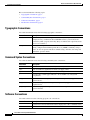
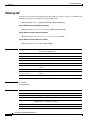
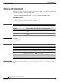
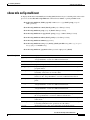
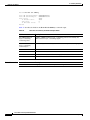
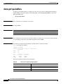
Typographic Conventions
Cisco IOS documentation uses the following typographic conventions:
Convention
Description
^ or Ctrl
Both the ^ symbol and Ctrl represent the Control (Ctrl) key on a keyboard. For
example, the key combination ^D or Ctrl-D means that you hold down the
Control key while you press the D key. (Keys are indicated in capital letters but
are not case sensitive.)
string
A string is a nonquoted set of characters shown in italics. For example, when
setting a Simple Network Management Protocol (SNMP) community string to
public, do not use quotation marks around the string; otherwise, the string will
include the quotation marks.
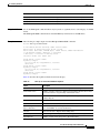
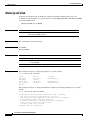
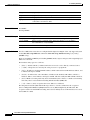
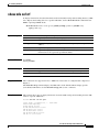
Command Syntax Conventions
Cisco IOS documentation uses the following command syntax conventions:
Convention
Description
bold
Bold text indicates commands and keywords that you enter as shown.
italic
Italic text indicates arguments for which you supply values.
[x]
Square brackets enclose an optional keyword or argument.
|
A vertical line, called a pipe, indicates a choice within a set of keywords
or arguments.
[x | y]
Square brackets enclosing keywords or arguments separated by a pipe indicate an
optional choice.
{x | y}
Braces enclosing keywords or arguments separated by a pipe indicate a
required choice.
[x {y | z}]
Braces and a pipe within square brackets indicate a required choice within an
optional element.
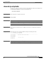
Software Conventions
Cisco IOS software uses the following program code conventions:
Convention
Description
Courier font
Courier font is used for information that is displayed on a PC or terminal screen.
Bold Courier font
Bold Courier font indicates text that the user must enter.
Cisco IOS IP Switching Command Reference
x
May 2008
About Cisco IOS Software Documentation
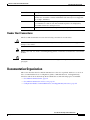
Documentation Organization
Convention
Description
<
Angle brackets enclose text that is not displayed, such as a password. Angle
brackets also are used in contexts in which the italic font style is not supported;
for example, ASCII text.
>
!
[
An exclamation point at the beginning of a line indicates that the text that follows
is a comment, not a line of code. An exclamation point is also displayed by
Cisco IOS software for certain processes.
]
Square brackets enclose default responses to system prompts.
Reader Alert Conventions
The Cisco IOS documentation set uses the following conventions for reader alerts:
Caution
Note
Timesaver
Means reader be careful. In this situation, you might do something that could result in equipment
damage or loss of data.
Means reader take note. Notes contain helpful suggestions or references to material not covered in the
manual.
Means the described action saves time. You can save time by performing the action described in the
paragraph.
Documentation Organization
This section describes the Cisco IOS documentation set, how it is organized, and how to access it on
Cisco.com. Included are lists of configuration guides, command references, and supplementary
references and resources that make up the documentation set. The following topics are included:
•
Cisco IOS Documentation Set, page xii
•
Cisco IOS Documentation on Cisco.com, page xii
•
Configuration Guides, Command References, and Supplementary Resources, page xiii
Cisco IOS IP Switching Command Reference
May 2008
xi
About Cisco IOS Software Documentation
Documentation Organization
Cisco IOS Documentation Set
Cisco IOS software documentation consists of the following:
•
Release notes and caveats provide information about platform, technology, and feature support for
a release and describe severity 1 (catastrophic), severity 2 (severe), and severity 3 (moderate) defects
in released Cisco IOS software code. Review release notes before other documents to learn whether
or not updates have been made to a feature.
•
Sets of configuration guides and command references organized by technology and published for
each standard Cisco IOS software release.
– Configuration guides—Compilations of documents that provide informational and
task-oriented descriptions of Cisco IOS software features.
– Command references—Compilations of commands that provide detailed information about the
commands used in the Cisco IOS features and processes that make up the related configuration
guides.
•
Lists of all the commands in a specific release and all commands that are new, modified, removed,
or replaced in the release.
•
Command reference book for debug commands. Commands are listed in alphabetical order.
•
Reference book for system messages for all Cisco IOS releases.
Cisco IOS Documentation on Cisco.com
The following sections describe the documentation organization and how to access various document
types.
Use Cisco Feature Navigator to find information about platform support and Cisco IOS and Catalyst OS
software image support. To access Cisco Feature Navigator, go to http://www.cisco.com/go/cfn. An
account on Cisco.com is not required.
New Features List
The New Features List for each release provides a list of all features in the release with hyperlinks to the
feature guides in which they are documented.
Feature Guides
Cisco IOS features are documented in feature guides. Feature guides describe one feature or a group of
related features that are supported on many different software releases and platforms. Your Cisco IOS
software release or platform may not support all the features documented in a feature guide. See the
Feature Information table at the end of the feature guide for information about which features in that
guide are supported in your software release.
Configuration Guides
Configuration guides are provided by technology and release and comprise a set of individual feature
guides relevant to the release and technology.
Command References
Command reference books contain Cisco IOS commands that are supported in many different software
releases and on many different platforms. The books are provided by technology. For information about
Cisco IOS commands, see the Cisco IOS Master Commands List, or the Command Lookup Tool at
http://tools.cisco.com/Support/CLILookup.
Cisco IOS IP Switching Command Reference
xii
May 2008
About Cisco IOS Software Documentation
Documentation Organization
Cisco IOS Supplementary Documents and Resources
Supplementary documents and resources are listed in Table 2 on page xvii.
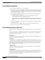
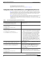
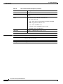
Configuration Guides, Command References, and Supplementary Resources
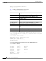
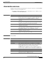
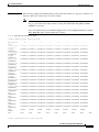
Table 1 lists in alphabetical order Cisco IOS software configuration guides and command references,
including brief descriptions of the contents of the documents. The configuration guides and command
references listed support many different software releases and platforms. Your Cisco IOS software
release or platform may not support all these technologies.
Table 2 lists documents and resources that supplement the Cisco IOS software configuration guides and
command references. These supplementary resources include release notes and caveats; master
command lists; new, modified, removed, and replaced command lists; system messages; and the debug
command reference.
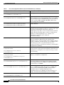
Table 1
Cisco IOS Configuration Guides and Command References
Configuration Guide and Command Reference Titles
Features/Protocols/Technologies
Cisco IOS AppleTalk Configuration Guide
AppleTalk protocol.
Cisco IOS AppleTalk Command Reference
Cisco IOS Asynchronous Transfer Mode
Configuration Guide
LAN ATM, multiprotocol over ATM (MPoA), and WAN ATM.
Cisco IOS Asynchronous Transfer Mode
Command Reference
Cisco IOS Bridging and IBM Networking
Configuration Guide
•
Transparent and source-route transparent (SRT) bridging,
source-route bridging (SRB), Token Ring Inter-Switch Link
(TRISL), and token ring route switch module (TRRSM).
•
Data-link switching plus (DLSw+), serial tunnel (STUN),
block serial tunnel (BSTUN); logical link control, type 2
(LLC2), synchronous data link control (SDLC); IBM
Network Media Translation, including Synchronous Data
Logical Link Control (SDLLC) and qualified LLC (QLLC);
downstream physical unit (DSPU), Systems Network
Architecture (SNA) service point, SNA frame relay access,
advanced peer-to-peer networking (APPN), native client
interface architecture (NCIA) client/server topologies, and
IBM Channel Attach.
Cisco IOS Bridging Command Reference
Cisco IOS IBM Networking Command Reference
Cisco IOS Broadband and DSL Configuration Guide
Cisco IOS Broadband and DSL Command Reference
Cisco IOS Carrier Ethernet Configuration Guide
Cisco IOS Carrier Ethernet Command Reference
Cisco IOS Configuration Fundamentals
Configuration Guide
Cisco IOS Configuration Fundamentals
Command Reference
Point-to-Point Protocol (PPP) over ATM (PPPoA) and PPP over
Ethernet (PPPoE).
Connectivity fault management (CFM), Ethernet Local
Management Interface (ELMI), IEEE 802.3ad link bundling,
Link Layer Discovery Protocol (LLDP), media endpoint
discovery (MED), and operations, administration, and
maintenance (OAM).
Autoinstall, Setup, Cisco IOS command-line interface (CLI),
Cisco IOS file system (IFS), Cisco IOS web browser user
interface (UI), basic file transfer services, and file management.
Cisco IOS IP Switching Command Reference
May 2008
xiii
About Cisco IOS Software Documentation
Documentation Organization
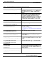
Table 1
Cisco IOS Configuration Guides and Command References (continued)
Configuration Guide and Command Reference Titles
Features/Protocols/Technologies
Cisco IOS DECnet Configuration Guide
DECnet protocol.
Cisco IOS DECnet Command Reference
Cisco IOS Dial Technologies Configuration Guide
Cisco IOS Dial Technologies Command Reference
Cisco IOS Flexible NetFlow Configuration Guide
Asynchronous communications, dial backup, dialer technology,
dial-in terminal services and AppleTalk remote access (ARA),
large scale dialout, dial-on-demand routing, dialout, modem and
resource pooling, ISDN, multilink PPP (MLP), PPP, virtual
private dialup network (VPDN).
Flexible NetFlow.
Cisco IOS Flexible NetFlow Command Reference
Cisco IOS H.323 Configuration Guide
Gatekeeper enhancements for managed voice services,
Gatekeeper Transaction Message Protocol, gateway codec order
preservation and shutdown control, H.323 dual tone
multifrequency relay, H.323 version 2 enhancements, Network
Address Translation (NAT) support of H.323 v2 Registration,
Admission, and Status (RAS) protocol, tokenless call
authorization, and VoIP gateway trunk and
carrier-based routing.
Cisco IOS High Availability Command Reference
A variety of High Availability (HA) features and technologies
that are available for different network segments (from
enterprise access to service provider core) to facilitate creation
of end-to-end highly available networks. Cisco IOS HA features
and technologies can be categorized in three key areas:
system-level resiliency, network-level resiliency, and embedded
management for resiliency.
Cisco IOS Intelligent Service Gateway
Configuration Guide
Cisco IOS Intelligent Service Gateway
Command Reference
Subscriber identification, service and policy determination,
session creation, session policy enforcement, session life-cycle
management, accounting for access and service usage, session
state monitoring.
Cisco IOS Interface and Hardware Component
Configuration Guide
LAN interfaces, logical interfaces, serial interfaces, virtual
interfaces, and interface configuration.
Cisco IOS Interface and Hardware Component
Command Reference
Cisco IOS IP Addressing Services Configuration Guide
Cisco IOS IP Addressing Services Command Reference
Cisco IOS IP Application Services Configuration Guide
Cisco IOS IP Application Services Command Reference
Cisco IOS IP Mobility Configuration Guide
Address Resolution Protocol (ARP), Network Address
Translation (NAT), Domain Name System (DNS), Dynamic
Host Configuration Protocol (DHCP), and Next Hop Address
Resolution Protocol (NHRP).
Enhanced Object Tracking (EOT), Gateway Load Balancing
Protocol (GLBP), Hot Standby Router Protocol (HSRP), IP
Services, Server Load Balancing (SLB), Stream Control
Transmission Protocol (SCTP), TCP, Web Cache
Communication Protocol (WCCP), User Datagram Protocol
(UDP), and Virtual Router Redundancy Protocol (VRRP).
Mobile ad hoc networks (MANet) and Cisco mobile networks.
Cisco IOS IP Mobility Command Reference
Cisco IOS IP Switching Command Reference
xiv
May 2008
About Cisco IOS Software Documentation
Documentation Organization
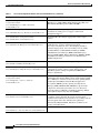
Table 1
Cisco IOS Configuration Guides and Command References (continued)
Configuration Guide and Command Reference Titles
Features/Protocols/Technologies
Cisco IOS IP Multicast Configuration Guide
Protocol Independent Multicast (PIM) sparse mode (PIM-SM),
bidirectional PIM (bidir-PIM), Source Specific Multicast
(SSM), Multicast Source Discovery Protocol (MSDP), Internet
Group Management Protocol (IGMP), and Multicast VPN
(MVPN).
Cisco IOS IP Multicast Command Reference
Cisco IOS IP Routing Protocols Configuration Guide
Cisco IOS IP Routing Protocols Command Reference
Cisco IOS IP SLAs Configuration Guide
Border Gateway Protocol (BGP), multiprotocol BGP,
multiprotocol BGP extensions for IP multicast, bidirectional
forwarding detection (BFD), Enhanced Interior Gateway
Routing Protocol (EIGRP), Interior Gateway Routing Protocol
(IGRP), Intermediate System-to-Intermediate System (IS-IS),
on-demand routing (ODR), Open Shortest Path First (OSPF),
and Routing Information Protocol (RIP).
Cisco IOS IP Service Level Agreements (IP SLAs).
Cisco IOS IP SLAs Command Reference
Cisco IOS IP Switching Configuration Guide
Cisco IOS IP Switching Command Reference
Cisco IOS IPv6 Configuration Guide
Cisco IOS IPv6 Command Reference
Cisco Express Forwarding, fast switching, and Multicast
Distributed Switching (MDS).
For IPv6 features, protocols, and technologies, go to the IPv6
“Start Here” document at
http://www.cisco.com/en/US/products/ps6441/products_configuration_guide_chapter09186a0080
1d65ed.html
Cisco IOS ISO CLNS Configuration Guide
ISO connectionless network service (CLNS).
Cisco IOS ISO CLNS Command Reference
Cisco IOS LAN Switching Configuration Guide
Cisco IOS LAN Switching Command Reference
Cisco IOS Mobile Wireless Gateway GPRS Support Node
Configuration Guide
Cisco IOS Mobile Wireless Gateway GPRS Support Node
Command Reference
Cisco IOS Mobile Wireless Home Agent
Configuration Guide
Cisco IOS Mobile Wireless Home Agent
Command Reference
Cisco IOS Mobile Wireless Packet Data Serving Node
Configuration Guide
Cisco IOS Mobile Wireless Packet Data Serving Node
Command Reference
Cisco IOS Mobile Wireless Radio Access Networking
Configuration Guide
VLANs, Inter-Switch Link (ISL) encapsulation, IEEE 802.10
encapsulation, IEEE 802.1Q encapsulation, and multilayer
switching (MLS).
Cisco IOS Gateway GPRS Support Node (GGSN) in a
2.5-generation general packet radio service (GPRS) and
3-generation universal mobile telecommunication system (UMTS)
network.
Cisco Mobile Wireless Home Agent, an anchor point for mobile
terminals for which mobile IP or proxy mobile IP services are
provided.
Cisco Packet Data Serving Node (PDSN), a wireless gateway that
is between the mobile infrastructure and standard IP networks and
that enables packet data services in a code division multiple access
(CDMA) environment.
Cisco IOS radio access network products.
Cisco IOS Mobile Wireless Radio Access Networking
Command Reference
Cisco IOS IP Switching Command Reference
May 2008
xv
About Cisco IOS Software Documentation
Documentation Organization
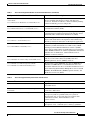
Table 1
Cisco IOS Configuration Guides and Command References (continued)
Configuration Guide and Command Reference Titles
Features/Protocols/Technologies
Cisco IOS Multiprotocol Label Switching
Configuration Guide
MPLS Label Distribution Protocol (LDP), MPLS Layer 2 VPNs,
MPLS Layer 3 VPNs, MPLS Traffic Engineering (TE), and
MPLS Embedded Management (EM) and MIBs.
Cisco IOS Multiprotocol Label Switching
Command Reference
Cisco IOS Multi-Topology Routing Configuration Guide
Cisco IOS Multi-Topology Routing Command Reference
Cisco IOS NetFlow Configuration Guide
Cisco IOS NetFlow Command Reference
Cisco IOS Network Management Configuration Guide
Cisco IOS Network Management Command Reference
Cisco IOS Novell IPX Configuration Guide
Unicast and multicast topology configurations, traffic
classification, routing protocol support, and network
management support.
Network traffic data analysis, aggregation caches, export
features.
Basic system management; system monitoring and logging;
troubleshooting, logging, and fault management;
Cisco Discovery Protocol; Cisco IOS Scripting with Tool
Control Language (Tcl); Cisco networking services (CNS);
DistributedDirector; Embedded Event Manager (EEM);
Embedded Resource Manager (ERM); Embedded Syslog
Manager (ESM); HTTP; Remote Monitoring (RMON); SNMP;
and VPN Device Manager Client for Cisco IOS Software
(XSM Configuration).
Novell Internetwork Packet Exchange (IPX) protocol.
Cisco IOS Novell IPX Command Reference
Cisco IOS Optimized Edge Routing Configuration Guide
Cisco IOS Optimized Edge Routing Command Reference
Cisco IOS Quality of Service Solutions
Configuration Guide
Cisco IOS Quality of Service Solutions
Command Reference
Cisco IOS Security Configuration Guide
Cisco IOS Security Command Reference
Optimized edge routing (OER) monitoring, policy
configuration, routing control, logging and reporting, and
VPN IPsec/generic routing encapsulation (GRE) tunnel
interface optimization.
Class-based weighted fair queuing (CBWFQ), custom queuing,
distributed traffic shaping (DTS), generic traffic shaping (GTS),
IP- to-ATM class of service (CoS), low latency queuing (LLQ),
modular QoS CLI (MQC), Network-Based Application
Recognition (NBAR), priority queuing, Security Device
Manager (SDM), Multilink PPP (MLPPP) for QoS, header
compression, AutoQoS, QoS features for voice, Resource
Reservation Protocol (RSVP), weighted fair queuing (WFQ),
and weighted random early detection (WRED).
Access control lists (ACLs), authentication, authorization, and
accounting (AAA), firewalls, IP security and encryption,
neighbor router authentication, network access security, network
data encryption with router authentication, public key
infrastructure (PKI), RADIUS, TACACS+, terminal access
security, and traffic filters.
Cisco IOS Service Selection Gateway Configuration Guide Subscriber authentication, service access, and accounting.
Cisco IOS Service Selection Gateway Command Reference
Cisco IOS IP Switching Command Reference
xvi
May 2008
About Cisco IOS Software Documentation
Documentation Organization
Table 1
Cisco IOS Configuration Guides and Command References (continued)
Configuration Guide and Command Reference Titles
Features/Protocols/Technologies
Cisco IOS Software Modularity Installation and Configuration Guide
Installation and basic configuration of software modularity
images, including installations on single and dual route
processors, installation rollbacks, software modularity binding,
software modularity processes and patches.
Cisco IOS Software Modularity Command Reference
Cisco IOS Terminal Services Configuration Guide
Cisco IOS Terminal Services Command Reference
DEC, local-area transport (LAT), and X.25 packet
assembler/disassembler (PAD).
Cisco IOS Virtual Switch Command Reference
Virtual switch redundancy, high availability, and packet handling;
converting between standalone and virtual switch modes; virtual
switch link (VSL); Virtual Switch Link Protocol (VSLP).
Cisco IOS Voice Configuration Library
Cisco IOS support for voice call control protocols, interoperability,
physical and virtual interface management, and troubleshooting.
The library includes documentation for IP telephony applications.
Cisco IOS Voice Command Reference
Cisco IOS VPDN Configuration Guide
Cisco IOS VPDN Command Reference
Cisco IOS Wide-Area Networking Configuration Guide
Cisco IOS Wide-Area Networking Command Reference
Cisco IOS Wireless LAN Configuration Guide
Cisco IOS Wireless LAN Command Reference
Table 2
Layer 2 Tunneling Protocol (L2TP) dial-out load balancing and
redundancy, L2TP extended failover, L2TP security VPDN,
multihop by Dialed Number Identification Service (DNIS),
timer and retry enhancements for L2TP and Layer 2 Forwarding
(L2F), RADIUS Attribute 82: tunnel assignment ID, shell-based
authentication of VPDN users, tunnel authentication via
RADIUS on tunnel terminator.
Frame Relay, Layer 2 Tunneling Protocol Version 3 (L2TPv3),
Link Access Procedure, Balanced (LAPB), Switched
Multimegabit Data Service (SMDS), and X.25.
Broadcast key rotation, IEEE 802.11x support, IEEE 802.1x
authenticator, IEEE 802.1x local authentication service for
Extensible Authentication Protocol-Flexible Authentication via
Secure Tunneling (EAP-FAST), Multiple Basic Service Set ID
(BSSID), Wi-Fi Multimedia (WMM) required elements, and
Wi-Fi Protected Access (WPA).
Cisco IOS Supplementary Documents and Resources
Document Title
Description
Cisco IOS Master Commands List
Alphabetical list of all the commands documented in the
Cisco IOS release.
Cisco IOS New, Modified, Removed, and Replaced
Commands
List of all the new, modified, removed, and replaced commands
for the Cisco IOS release.
Cisco IOS Software System Messages
List of Cisco IOS system messages and descriptions. System
messages may indicate problems with your system; be
informational only; or may help diagnose problems with
communications lines, internal hardware, or the
system software.
Cisco IOS Debug Command Reference
Alphabetical list of debug commands including brief
descriptions of use, command syntax, and usage guidelines.
Cisco IOS IP Switching Command Reference
May 2008
xvii
About Cisco IOS Software Documentation
Additional Resources and Documentation Feedback
Table 2
Cisco IOS Supplementary Documents and Resources (continued)
Document Title
Description
Release Notes and Caveats
Information about new and changed features, system
requirements, and other useful information about specific
software releases; information about defects in specific
Cisco IOS software releases.
MIBs
Files used for network monitoring. To locate and download
MIBs for selected platforms, Cisco IOS releases, and feature
sets, use Cisco MIB Locator at
http://www.cisco.com/go/mibs
RFCs
Standards documents maintained by the Internet Engineering
Task Force (IETF) that Cisco IOS software documentation
references where applicable. The full text of referenced RFCs
may be obtained at
http://www.rfc-editor.org/
Additional Resources and Documentation Feedback
What’s New in Cisco Product Documentation is published monthly and describes all new and revised
Cisco technical documentation. The What’s New in Cisco Product Documentation publication also
provides information about obtaining the following resources:
•
Technical documentation
•
Cisco product security overview
•
Product alerts and field notices
•
Technical assistance
Cisco IOS technical documentation includes embedded feedback forms where you can rate documents
and provide suggestions for improvement. Your feedback helps us improve our documentation.
CCDE, CCENT, Cisco Eos, Cisco Lumin, Cisco StadiumVision, the Cisco logo, DCE, and Welcome to the Human Network are trademarks;
Changing the Way We Work, Live, Play, and Learn is a service mark; and Access Registrar, Aironet, AsyncOS, Bringing the Meeting To You,
Catalyst, CCDA, CCDP, CCIE, CCIP, CCNA, CCNP, CCSP, CCVP, Cisco, the Cisco Certified Internetwork Expert logo, Cisco IOS, Cisco Press,
Cisco Systems, Cisco Systems Capital, the Cisco Systems logo, Cisco Unity, Collaboration Without Limitation, EtherFast, EtherSwitch, Event
Center, Fast Step, Follow Me Browsing, FormShare, GigaDrive, HomeLink, Internet Quotient, IOS, iPhone, iQ Expertise, the iQ logo, iQ Net
Readiness Scorecard, iQuick Study, IronPort, the IronPort logo, LightStream, Linksys, MediaTone, MeetingPlace, MGX, Networkers, Networking
Academy, Network Registrar, PCNow, PIX, PowerPanels, ProConnect, ScriptShare, SenderBase, SMARTnet, Spectrum Expert, StackWise, The
Fastest Way to Increase Your Internet Quotient, TransPath, WebEx, and the WebEx logo are registered trademarks of Cisco Systems, Inc. and/or its
affiliates in the United States and certain other countries.
All other trademarks mentioned in this document or Website are the property of their respective owners. The use of the word partner does not imply
a partnership relationship between Cisco and any other company. (0804R)
© 2007–2008 Cisco Systems, Inc. All rights reserved.
Cisco IOS IP Switching Command Reference
xviii
May 2008
Using the Command-Line Interface
in Cisco IOS Software
This document provides basic information about the command-line interface (CLI) in Cisco IOS
software and how you can use some of the CLI features. This document contains the following sections:
•
Initially Configuring a Device, page xix
•
Using the CLI, page xx
•
Saving Changes to a Configuration, page xxviii
•
Additional Information, page xxix
For more information about using the CLI, see the “Using the Cisco IOS Command-Line Interface
(CLI)” section of the Cisco IOS Configuration Fundamentals Configuration Guide.
For information about the Cisco IOS software documentation set, see “About Cisco IOS Software
Documentation.”
Initially Configuring a Device
Initially configuring a device varies by platform. For information about performing an initial
configuration, see the hardware installation documentation that is provided with the original packaging
of the product or go to the Product Support area of Cisco.com at
http://www.cisco.com/web/psa/products/index.html.
After you have performed the initial configuration and connected the device to your network, you can
configure the device either by using the console port or Telnet to access the Cisco IOS CLI or by using
the configuration method provided on the device, such as Security Device Manager.
Changing the Default Settings for a Console or AUX Port
There are only two changes that you can make to a console port and an AUX port:
•
Change the port speed with the config-register 0x command. Changing the port speed is not
recommended. The well-known default speed is 9600.
•
Change the behavior of the port; for example, by adding a password or changing the timeout value.
Cisco IOS IP Switching Command Reference
May 2008
xix
Using the Command-Line Interface in Cisco IOS Software
Using the CLI
Using the CLI
This section describes the following topics:
•
Understanding Command Modes, page xx
•
Using the Interactive Help Feature, page xxii
•
Understanding Command Syntax, page xxiii
•
Understanding Enable and Enable Secret Passwords, page xxiv
•
Using the Command History Feature, page xxv
•
Abbreviating Commands, page xxvi
•
Using Aliases for CLI Commands, page xxvi
•
Using the no and default Forms of Commands, page xxvi
•
Using the debug Command, page xxvii
•
Filtering Output Using Output Modifiers, page xxvii
•
Understanding CLI Error Messages, page xxviii
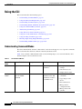
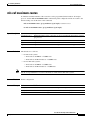
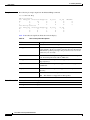
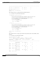
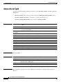
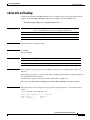
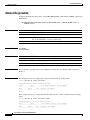
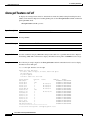
Understanding Command Modes
The CLI command mode structure is hierarchical, and each mode supports a set of specific commands.
This section describes the most common of the many modes that exist.
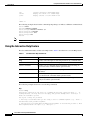
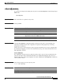
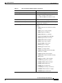
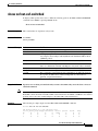
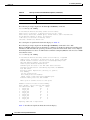
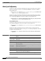
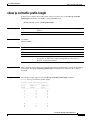
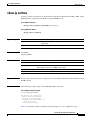
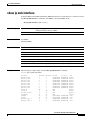
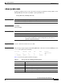
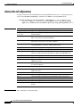
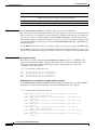
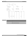
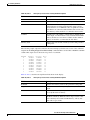
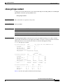
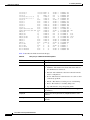
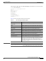
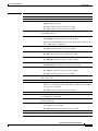
Table 3 lists common command modes with associated CLI prompts, access and exit methods, and a
brief description of how each mode is used.
Table 3
CLI Command Modes
Command
Mode
Access Method
Prompt
Exit Method
User EXEC
Log in.
Router>
Issue the logout or exit
command.
Privileged
EXEC
From user EXEC mode,
issue the enable
command.
Router#
Issue the disable
command or the exit
command to return to
user EXEC mode.
Mode Usage
•
Change terminal
settings.
•
Perform basic tests.
•
Display device status.
•
Issue show and debug
commands.
•
Copy images to the
device.
•
Reload the device.
•
Manage device
configuration files.
•
Manage device file
systems.
Cisco IOS IP Switching Command Reference
xx
May 2008
Using the Command-Line Interface in Cisco IOS Software
Using the CLI
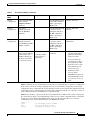
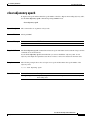
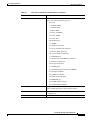
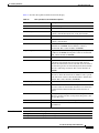
Table 3
CLI Command Modes (continued)
Command
Mode
Access Method
Prompt
Exit Method
Global
configuration
From privileged EXEC
mode, issue the
configure terminal
command.
Router(config)#
Issue the exit command Configure the device.
or the end command to
return to privileged
EXEC mode.
Interface
configuration
From global
configuration mode,
issue the interface
command.
Router(config-if)#
Issue the exit command Configure individual
to return to global
interfaces.
configuration mode or
the end command to
return to privileged
EXEC mode.
Line
configuration
From global
configuration mode,
issue the line vty or line
console command.
Router(config-line)#
Issue the exit command Configure individual
to return to global
terminal lines.
configuration mode or
the end command to
return to privileged
EXEC mode.
ROM monitor
From privileged EXEC
mode, issue the reload
command. Press the
Break key during the
first 60 seconds while
the system is booting.
rommon # >
Issue the continue
command.
# is the line number
and increments at
each prompt.
Mode Usage
•
Runs as the default
operating mode when a
valid Cisco IOS image
cannot be loaded.
•
Access the fall-back
procedure for loading a
Cisco IOS image when
the device lacks a valid
Cisco IOS image and
cannot be booted.
•
Perform password
recovery when a
CTRL-Break sequence is
issued within 60 seconds
of a power-on or reload
event.
EXEC commands are not saved when the software reboots. Commands that you issue in a configuration
mode can be saved to the startup configuration. If you save the running configuration to the startup
configuration, these commands will execute when the software is rebooted. Global configuration mode
is the highest level of configuration mode. From global configuration mode, you can enter a variety of
other configuration modes, including protocol-specific modes.
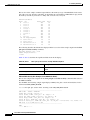
ROM monitor mode is a separate mode that is used when the Cisco IOS software cannot load properly.
If a valid software image is not found when the software boots or if the configuration file is corrupted at
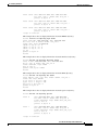
startup, the software might enter ROM monitor mode. Use the question symbol (?) to view the
commands that you can use while the device is in ROM monitor mode.
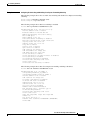
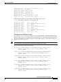
rommon 1 > ?
alias
boot
confreg
set and display aliases command
boot up an external process
configuration register utility
Cisco IOS IP Switching Command Reference
May 2008
xxi
Using the Command-Line Interface in Cisco IOS Software
Using the CLI
cont
context
cookie
.
.
.
rommon 2 >
continue executing a downloaded image
display the context of a loaded image
display contents of cookie PROM in hex
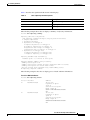
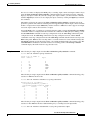
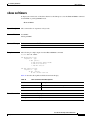
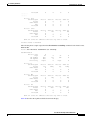
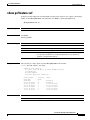
The following example shows how the command prompt changes to indicate a different command mode:
Router> enable
Router# configure terminal
Router(config)# interface ethernet 1/1
Router(config-if)# ethernet
Router(config-line)# exit
Router(config)# end
Router#
Note
A keyboard alternative to the end command is Ctrl-Z.
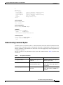
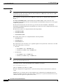
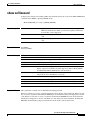
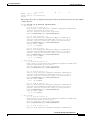
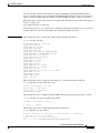
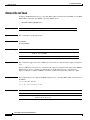
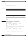
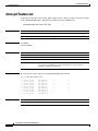
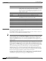
Using the Interactive Help Feature
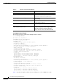
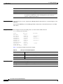
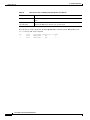
The Cisco IOS CLI includes an interactive Help feature. Table 4 describes how to use the Help feature.
Table 4
CLI Interactive Help Commands
Command
Purpose
help
Provides a brief description of the help feature in any command mode.
?
Lists all commands available for a particular command mode.
partial command?
Provides a list of commands that begin with the character string (no
space between the command and the question mark).
partial command<Tab>
Completes a partial command name (no space between the command
and <Tab>).
command ?
Lists the keywords, arguments, or both associated with the command
(space between the command and the question mark).
command keyword ?
Lists the arguments that are associated with the keyword (space between
the keyword and the question mark).
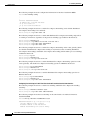
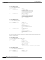
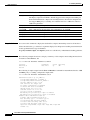
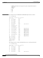
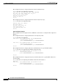
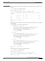
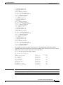
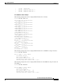
The following examples show how to use the help commands:
help
Router> help
Help may be requested at any point in a command by entering a question mark '?'. If
nothing matches, the help list will be empty and you must backup until entering a '?'
shows the available options.
Two styles of help are provided:
1. Full help is available when you are ready to enter a command argument (e.g. 'show ?')
and describes each possible argument.
2. Partial help is provided when an abbreviated argument is entered and you want to know
what arguments match the input (e.g. 'show pr?'.)
Cisco IOS IP Switching Command Reference
xxii
May 2008
Using the Command-Line Interface in Cisco IOS Software
Using the CLI
?
Router# ?
Exec commands:
access-enable
access-profile
access-template
alps
archive
<snip>
Create a temporary access-List entry
Apply user-profile to interface
Create a temporary access-List entry
ALPS exec commands
manage archive files
partial command?
Router(config)# zo?
zone zone-pair
partial command<Tab>
Router(config)# we<Tab> webvpn
command ?
Router(config-if)# pppoe ?
enable
Enable pppoe
max-sessions Maximum PPPOE sessions
command keyword ?
Router(config-if)# pppoe enable ?
group attach a BBA group
<cr>
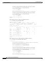
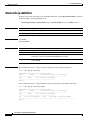
Understanding Command Syntax
Command syntax is the format in which a command should be entered in the CLI. Commands include
the name of the command, keywords, and arguments. Keywords are alphanumeric strings that are used
literally. Arguments are placeholders for values that a user must supply. Keywords and arguments may
be required or optional.
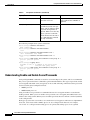
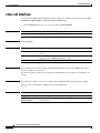
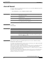
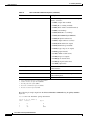
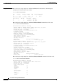
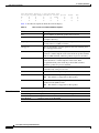
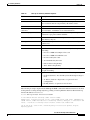
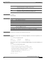
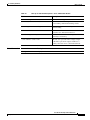
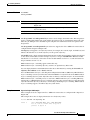
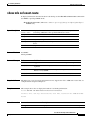
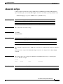
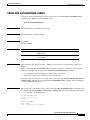
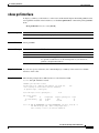
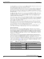
Specific conventions convey information about syntax and command elements. Table 5 describes these
conventions.
Table 5
CLI Syntax Conventions
Symbol/Text
Function
Notes
< > (angle brackets)
Indicate that the option is an
argument.
Sometimes arguments are displayed
without angle brackets.
A.B.C.D.
Indicates that you must enter a
dotted decimal IP address.
Angle brackets (< >) are not always
used to indicate that an IP address is
an argument.
WORD (all capital letters)
Indicates that you must enter
one word.
Angle brackets (< >) are not always
used to indicate that a WORD is an
argument.
Cisco IOS IP Switching Command Reference
May 2008
xxiii
Using the Command-Line Interface in Cisco IOS Software
Using the CLI
Table 5
CLI Syntax Conventions (continued)
Symbol/Text
Function
Notes
LINE (all capital letters)
Indicates that you must enter
more than one word.
Angle brackets (< >) are not always
used to indicate that a LINE is an
argument.
<cr> (carriage return)
Indicates the end of the list of —
available keywords and arguments, and also indicates when
keywords and arguments are
optional. When <cr> is the only
option, you have reached the
end of the branch or the end of
the command if the command
has only one branch.
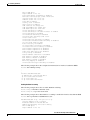
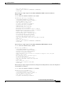
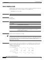
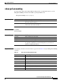
The following examples show syntax conventions:
Router(config)# ethernet cfm domain ?
WORD domain name
Router(config)# ethernet cfm domain dname ?
level
Router(config)# ethernet cfm domain dname level ?
<0-7> maintenance level number
Router(config)# ethernet cfm domain dname level 7 ?
<cr>
Router(config)# snmp-server file-transfer access-group 10 ?
protocol protocol options
<cr>
Router(config)# logging host ?
Hostname or A.B.C.D IP address of the syslog server
ipv6
Configure IPv6 syslog server
Router(config)# snmp-server file-transfer access-group 10 ?
protocol protocol options
<cr>
Understanding Enable and Enable Secret Passwords
Some privileged EXEC commands are used for actions that impact the system, and it is recommended
that you set a password for these commands to prevent unauthorized use. Two types of passwords, enable
(not encrypted) and enable secret (encrypted), can be set. The following commands set these passwords
and are issued in global configuration mode:
•
enable password
•
enable secret password
Using an enable secret password is recommended because it is encrypted and more secure than the
enable password. When you use an enable secret password, text is encrypted (unreadable) before it is
written to the config.text file. When you use an enable password, the text is written as entered (readable)
to the config.text file.
Each type of password is case sensitive, can contain from 1 to 25 uppercase and lowercase alphanumeric
characters, and can start with a number. Spaces are also valid password characters; for example,
“two words” is a valid password. Leading spaces are ignored, but trailing spaces are recognized.
Cisco IOS IP Switching Command Reference
xxiv
May 2008
Using the Command-Line Interface in Cisco IOS Software
Using the CLI
Note
Both password commands have numeric keywords that are single integer values. If you choose a number
for the first character of your password followed by a space, the system will read the number as if it were
the numeric keyword and not as part of your password.
When both passwords are set, the enable secret password takes precedence over the enable password.
To remove a password, use the no form of the commands: no enable password or
no enable secret password.
For more information about password recovery procedures for Cisco products, see
http://www.cisco.com/en/US/products/sw/iosswrel/ps1831/
products_tech_note09186a00801746e6.shtml.
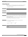
Using the Command History Feature
The CLI command history feature saves the commands you enter during a session in a command history
buffer. The default number of commands saved is 10, but the number is configurable within the range of
0 to 256. This command history feature is particularly useful for recalling long or complex commands.
To change the number of commands saved in the history buffer for a terminal session, issue the
terminal history size command:
Router# terminal history size num
A command history buffer is also available in line configuration mode with the same default and
configuration options. To set the command history buffer size for a terminal session in line configuration
mode, issue the history command:
Router(config-line)# history [size num]
To recall commands from the history buffer, use the following methods:
•
Press Ctrl-P or the up arrow key—Recalls commands beginning with the most recent command.
Repeat the key sequence to recall successively older commands.
•
Press Ctrl-N or the down arrow key—Recalls the most recent commands in the history buffer after
they have been recalled using Ctrl-P or the up arrow key. Repeat the key sequence to recall
successively more recent commands.
Note
•
The arrow keys function only on ANSI-compatible terminals such as the VT100.
Issue the show history command in user EXEC or privileged EXEC mode—Lists the most recent
commands that you entered. The number of commands that are displayed is determined by the
setting of the terminal history size and history commands.
The CLI command history feature is enabled by default. To disable this feature for a terminal
session, issue the terminal no history command in user EXEC or privileged EXEC mode or the
no history command in line configuration mode.
Cisco IOS IP Switching Command Reference
May 2008
xxv
Using the Command-Line Interface in Cisco IOS Software
Using the CLI
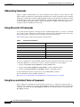
Abbreviating Commands
Typing a complete command name is not always required for the command to execute. The Cisco IOS
CLI recognizes an abbreviated command when the abbreviation contains enough characters to uniquely
identify the command. For example, the show version command can be abbreviated as sh ver. It cannot
be abbreviated as s ver because s could mean show, set, or systat. The sh v abbreviation also is not valid
because the show command has vrrp as a keyword in addition to version. (Command and keyword
examples from Cisco IOS Release 12.4(13)T.)
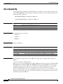
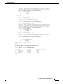
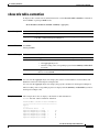
Using Aliases for CLI Commands
To save time and the repetition of entering the same command multiple times, you can use a command
alias. An alias can be configured to do anything that can be done at the command line, but an alias cannot
move between modes, type in passwords, or perform any interactive functions.
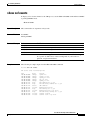
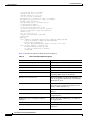
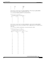
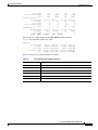
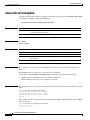
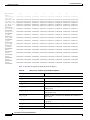
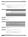
Table 6 shows the Cisco IOS software default command aliases.
Table 6
Default Command Aliases
Command Alias
Original Command
h
help
lo
logout
p
ping
s
show
u or un
undebug
w
where
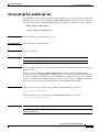
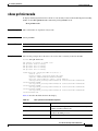
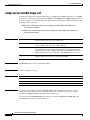
To create a command alias, issue the alias command in global configuration mode. The syntax of the
command is alias mode command-alias original-command. Following are some examples:
•
Router(config)# alias exec prt partition—privileged EXEC mode
•
Router(config)# alias configure sb source-bridge—global configuration mode
•
Router(config)# alias interface rl rate-limit—interface configuration mode
To view both default and user-created aliases, issue the show alias command.
For more information about the alias command, see
http://www.cisco.com/en/US/docs/ios/fundamentals/command/reference/cf_book.html.
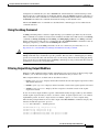
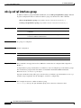
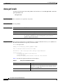
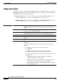
Using the no and default Forms of Commands
Most configuration commands have a no form that is used to reset a command to its default value or
disable a feature or function. For example, the ip routing command is enabled by default. To disable this
command, you would issue the no ip routing command. To re-enable IP routing, you would issue the
ip routing command.
Cisco IOS IP Switching Command Reference
xxvi
May 2008
Using the Command-Line Interface in Cisco IOS Software
Using the CLI
Configuration commands may also have a default form, which returns the command settings to their
default values. For commands that are disabled by default, using the default form has the same effect as
using the no form of the command. For commands that are enabled by default and have default settings,
the default form enables the command and returns the settings to their default values.
The no and default forms of commands are described in the command pages of Cisco IOS software
command references.
Using the debug Command
A debug command produces extensive output that helps you troubleshoot problems in your network.
These commands are available for many features and functions within Cisco IOS software. Some debug
commands are debug all, debug aaa accounting, and debug mpls packets. To use debug commands
during a Telnet session with a device, you must first enter the terminal monitor command. To turn off
debugging completely, you must enter the undebug all command.
For more information about debug commands, see the Cisco IOS Debug Command Reference at
http://www.cisco.com/en/US/docs/ios/debug/command/reference/db_book.html.
Caution
Debugging is a high priority and high CPU utilization process that can render your device unusable. Use
debug commands only to troubleshoot specific problems. The best times to run debugging are during
periods of low network traffic and when few users are interacting with the network. Debugging during
these periods decreases the likelihood that the debug command processing overhead will affect network
performance or user access or response times.
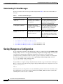
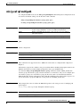
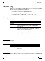
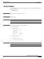
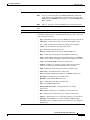
Filtering Output Using Output Modifiers
Many Cisco IOS commands produce lengthy output that may use several screens to display. Using output
modifiers, you can filter this output to show only the information that you want to see.
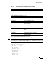
Three output modifiers are available and are described as follows:
•
begin regular expression—Displays the first line in which a match of the regular expression is found
and all lines that follow.
•
include regular expression—Displays all lines in which a match of the regular expression is found.
•
exclude regular expression—Displays all lines except those in which a match of the regular
expression is found.
To use one of these output modifiers, type the command followed by the pipe symbol (|), the modifier,
and the regular expression that you want to search for or filter. A regular expression is a case-sensitive
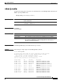
alphanumeric pattern. It can be a single character or number, a phrase, or a more complex string.
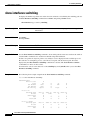
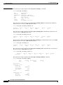
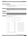
The following example illustrates how to filter output of the show interface command to display only
lines that include the expression “protocol.”
Router# show interface | include protocol
FastEthernet0/0 is up, line protocol is up
Serial4/0 is up, line protocol is up
Serial4/1 is up, line protocol is up
Serial4/2 is administratively down, line protocol is down
Serial4/3 is administratively down, line protocol is down
Cisco IOS IP Switching Command Reference
May 2008
xxvii
Using the Command-Line Interface in Cisco IOS Software
Saving Changes to a Configuration
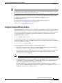
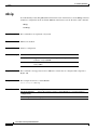
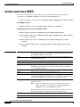
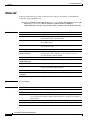
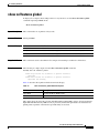
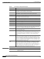
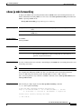
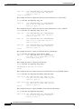
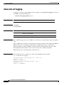
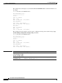
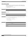
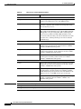
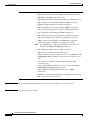
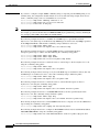
Understanding CLI Error Messages
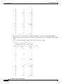
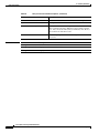
You may encounter some error messages while using the CLI. Table 7 shows the common CLI error
messages.
Table 7
Common CLI Error Messages
Error Message
Meaning
% Ambiguous command:
“show con”
You did not enter enough
R-enter the command followed by a
characters for the command to space and a question mark (?). The
be recognized.
keywords that you are allowed to
enter for the command appear.
% Incomplete command.
You did not enter all the
keywords or values required
by the command.
% Invalid input detected at “^” You entered the command inmarker.
correctly. The caret (^) marks
the point of the error.
How to Get Help
Reenter the command followed by a
space and a question mark (?). The
keywords that you are allowed to
enter for the command appear.
Enter a question mark (?) to display
all the commands that are available in
this command mode. The keywords
that you are allowed to enter for the
command appear.
For more system error messages, see the following documents:
•
Cisco IOS Release 12.2SR System Message Guide
•
Cisco IOS System Messages, Volume 1 of 2 (Cisco IOS Release 12.4)
•
Cisco IOS System Messages, Volume 2 of 2 (Cisco IOS Release 12.4)
Saving Changes to a Configuration
To save changes that you made to the configuration of a device, you must issue the copy running-config
startup-config command or the copy system:running-config nvram:startup-config command. When
you issue these commands, the configuration changes that you made are saved to the startup
configuration and saved when the software reloads or power to the device is turned off or interrupted.
The following example shows the syntax of the copy running-config startup-config command:
Router# copy running-config startup-config
Destination filename [startup-config]?
You press Enter to accept the startup-config filename (the default), or type a new filename and then press
Enter to accept that name. The following output is displayed indicating that the configuration was saved:
Building configuration...
[OK]
Router#
On most platforms, the configuration is saved to NVRAM. On platforms with a Class A flash file system,
the configuration is saved to the location specified by the CONFIG_FILE environment variable. The
CONFIG_FILE variable defaults to NVRAM.
Cisco IOS IP Switching Command Reference
xxviii
May 2008
Using the Command-Line Interface in Cisco IOS Software
Additional Information
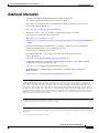
Additional Information
•
“Using the Cisco IOS Command-Line Interface (CLI)” section of the
Cisco IOS Configuration Fundamentals Configuration Guide.
http://www.cisco.com/en/US/docs/ios/fundamentals/configuration/guide/cf_cli-basics.html
•
Cisco Product Support Resources
http://www.cisco.com/web/psa/products/index.html
•
Support area on Cisco.com (also search for documentation by task or product)
http://www.cisco.com/en/US/support/index.html
•
White Paper: Cisco IOS Reference Guide
http://www.cisco.com/en/US/products/sw/iosswrel/ps1828/products_white_paper09186a00801830
5e.shtml
•
Software Download Center (downloads; tools; licensing, registration, advisory, and general
information) (requires Cisco.com User ID and password)
http://www.cisco.com/kobayashi/sw-center/
•
Error Message Decoder, a tool to help you research and resolve error messages for
Cisco IOS software
http://www.cisco.com/pcgi-bin/Support/Errordecoder/index.cgi
•
Command Lookup Tool, a tool to help you find detailed descriptions of Cisco IOS commands
(requires Cisco.com User ID and password)
http://tools.cisco.com/Support/CLILookup/cltSearchAction.do
•
Output Interpreter, a troubleshooting tool that analyzes command output of supported
show commands
https://www.cisco.com/pcgi-bin/Support/OutputInterpreter/home.pl\
CCDE, CCENT, Cisco Eos, Cisco Lumin, Cisco StadiumVision, the Cisco logo, DCE, and Welcome to the Human Network are trademarks;
Changing the Way We Work, Live, Play, and Learn is a service mark; and Access Registrar, Aironet, AsyncOS, Bringing the Meeting To You,
Catalyst, CCDA, CCDP, CCIE, CCIP, CCNA, CCNP, CCSP, CCVP, Cisco, the Cisco Certified Internetwork Expert logo, Cisco IOS, Cisco Press,
Cisco Systems, Cisco Systems Capital, the Cisco Systems logo, Cisco Unity, Collaboration Without Limitation, EtherFast, EtherSwitch, Event
Center, Fast Step, Follow Me Browsing, FormShare, GigaDrive, HomeLink, Internet Quotient, IOS, iPhone, iQ Expertise, the iQ logo, iQ Net
Readiness Scorecard, iQuick Study, IronPort, the IronPort logo, LightStream, Linksys, MediaTone, MeetingPlace, MGX, Networkers, Networking
Academy, Network Registrar, PCNow, PIX, PowerPanels, ProConnect, ScriptShare, SenderBase, SMARTnet, Spectrum Expert, StackWise, The
Fastest Way to Increase Your Internet Quotient, TransPath, WebEx, and the WebEx logo are registered trademarks of Cisco Systems, Inc. and/or its
affiliates in the United States and certain other countries.
All other trademarks mentioned in this document or Website are the property of their respective owners. The use of the word partner does not imply
a partnership relationship between Cisco and any other company. (0804R)
Any Internet Protocol (IP) addresses used in this document are not intended to be actual addresses. Any examples, command display output, and
figures included in the document are shown for illustrative purposes only. Any use of actual IP addresses in illustrative content is unintentional and
coincidental.
© 2007–2008 Cisco Systems, Inc. All rights reserved.
Cisco IOS IP Switching Command Reference
May 2008
xxix
Using the Command-Line Interface in Cisco IOS Software
Additional Information
Cisco IOS IP Switching Command Reference
xxx
May 2008
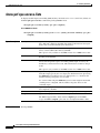
Introduction
This document describes the commands used to configure IP switching features such as Cisco Express
Forwarding, Distributed Cisco Express Forwarding, and Fast Switching in Cisco IOS software.
Note
Prior to Cisco IOS Release 12.3(14)T, the commands for configuring IP switching features were
presented in the Cisco IOS Switching Services Command Reference.
Refer to the configuration guide indicated here for configuration guidelines:
For Guidelines About Configuring
This Cisco IOS Feature...
IP switching features
Refer to the Following Cisco IOS Configuration Guide...
•
Cisco IOS IP Switching Configuration Guide.
Cisco IOS IP Switching Command Reference
May 2008
ISW-1
Introduction
Cisco IOS IP Switching Command Reference
ISW-2
May 2008
IP Switching Commands
Cisco IOS IP Switching Command Reference
May 2008
ISW-3
IP Switching Commands
cef table consistency-check
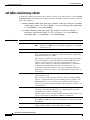
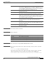
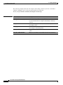
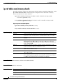
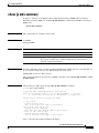
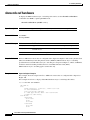
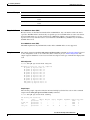
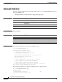
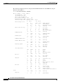
cef table consistency-check
To enable Cisco Express Forwarding table consistency checker types and parameters, use the cef table
consistency-check command in global configuration mode. To disable consistency checkers, use the no
form of this command.
cef table consistency-check {ipv4 | ipv6} [type {lc-detect | scan-lc-rp | scan-rp-lc | scan-rib-ios
| scan-ios-rib}] [count count-number] [period seconds] [error-message] [auto-repair delay
seconds holddown seconds] [data-checking]
no cef table consistency-check {ipv4 | ipv6} [type {lc-detect | scan-lc-rp | scan-rp-lc |
scan-rib-ios | scan-ios-rib}] [count count-number] [period seconds] [error-message]
[auto-repair delay seconds holddown seconds] [data-checking]
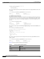
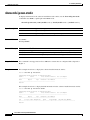
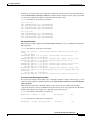
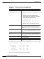
Syntax Description
ipv4
Checks IPv4 addresses.
ipv6
Checks IPv6 addresses.
Note
On the Cisco 10000 series routers, IPv6 is supported on 12.2(28)SB
and later releases.
type
(Optional) Specifies the type of consistency check to enable.
lc-detect
(Optional) (Distributed platforms such as the Cisco 7500 series only)
Detects missing prefixes on the line card. The information is confirmed by
the Route Switch Processor (RSP).
This consistency checker operates on the line card by retrieving IP prefixes
that are missing from its Forwarding Information Base (FIB) table. If IP
prefixes are missing, the line card cannot forward packets for these
addresses. This consistency checker then sends IP prefixes to the RSP for
confirmation. If the RSP detects that it has the relevant entry, an
inconsistency is detected, and an error message is displayed. Finally, the
RSP sends a signal back to the line card confirming that the IP prefix is an
inconsistency.
scan-lc-rp
(Optional) (Distributed platforms only) Performs a passive scan check of
tables on the line card.
This consistency checker operates on the line card by examining the FIB
table for a configurable time period and sending the next x prefixes to the
RSP. The RSP does an exact lookup, and if it finds the prefix missing, it
reports an inconsistency. Finally, the RSP sends a signal back to the line card
for confirmation.
scan-rp-lc
(Optional) Operates on the RSP (opposite of the scan-lc-rp consistency
checker) by examining the FIB table for a configurable time period and
sending the next x prefixes to the line card.
The line card does an exact lookup. If it finds the prefix missing, the line card
reports an inconsistency and signals the RSP for confirmation.
scan-rib-ios
(Optional) (Distributed platforms only) Compares the Routing Information
Base (RIB) to the FIB table and provides the number of entries missing from
the FIB table.
scan-ios-rib
(Optional) (Distributed platforms only) Compares the FIB table to the RIB
and provides the number of entries missing from the RIB.
Cisco IOS IP Switching Command Reference
ISW-4
May 2008
IP Switching Commands
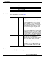
cef table consistency-check
count count-number
(Optional) Specifies the maximum number of prefixes to check per scan. The
range is from 2 to 10000. The default count number is 1000 prefixes per scan
for the scan-rib-ios and scan-ios-rib keywords. The default count number is
0 for the lc-detect, scan-lc-rp, and scan-rp-lc keywords.
period seconds
(Optional) Period between scans. Valid values are from 30 to 3600 seconds.
The default is 60 seconds.
error-message
(Optional) Enables the consistency checker to generate an error message
when it detects an inconsistency. By default, this function is disabled.
auto-repair
(Optional) Enables the auto repair function. By default, this function is
enabled. You can enter the no form of the command to disable auto repair or
enter the default form of the command to return the auto repair settings to a
10-second delay and 300-second holddown.
delay seconds
(Optional) Specifies how long the consistency checker waits to fix an
inconsistency. The range is 10 to 300 seconds. The default delay is
10 seconds.
holddown seconds
(Optional) Specifies how long the consistency checker waits to reenable auto
repair after auto repair runs. The range is from 300 to 3000 seconds. The
default delay is 300 seconds.
data-checking
(Optional) Enables the consistency checker data-checking utility. By default,
this function is disabled.
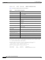
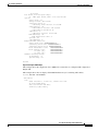
Command Default
All consistency checkers are disabled.
Command Modes
Global configuration
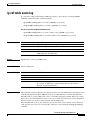
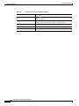
Command History
Release
Modification
12.2(25)S
This command was introduced.
12.2(28)SB
This command was integrated into Cisco IOS Release 12.2(28)SB.
12.2(33)SRA
This command was integrated into Cisco IOS Release 12.2(33)SRA.
12.2(33)SXH
This command was integrated into Cisco IOS Release 12.2(33)SXH.
Usage Guidelines
This command replaces the ip cef table consistency-check command.
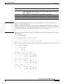
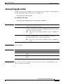
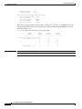
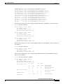
Examples
The following example enables the Cisco Express Forwarding consistency checker to check IPv4
addresses:
Router(config)# cef table consistency-check ipv4
The following example enables the Cisco Express Forwarding consistency checker to check IPv4
addresses and specifies the scan-rp-lc checker to run every 60 seconds for 5000 prefixes:
Router(config)# cef table consistency-check ipv4 type scan-rp-lc count 5000 period 60
Cisco IOS IP Switching Command Reference
May 2008
ISW-5
IP Switching Commands
cef table consistency-check
The following example enables the Cisco Express Forwarding consistency checker to check IPv4
addresses and display an error message when it finds an inconsistency:
Router(config)# cef table consistency-check ipv4 error-message
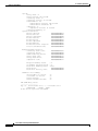
Related Commands
Command
Description
clear cef table
Clears the Cisco Express Forwarding tables.
clear ip cef inconsistency
Clears Cisco Express Forwarding inconsistency statistics and
records found by the Cisco Express Forwarding consistency
checkers.
debug cef
Enables the display of information about Cisco Express
Forwarding events.
debug ip cef table
Enables the collection of events that affect entries in the
Cisco Express Forwarding tables.
show cef table consistency-check Displays Cisco Express Forwarding consistency checker table
values.
show ip cef inconsistency
Displays Cisco Express Forwarding IP prefix inconsistencies.
Cisco IOS IP Switching Command Reference
ISW-6
May 2008
IP Switching Commands
clear adjacency
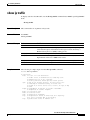
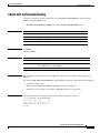
clear adjacency
To clear the Cisco Express Forwarding adjacency table, use the clear adjacency command in privileged
EXEC mode.
clear adjacency
Syntax Description
This command has no arguments or keywords.
Command Modes
Privileged EXEC
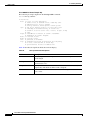
Command History
Release
Modification
11.2GS
This command was introduced to support the Cisco 12012 Internet router.
11.1CC
Support was added for multiple platforms.
12.2(25)S
This command was integrated into Cisco IOS Release 12.2(25)S.
12.2(28)SB
This command was integrated into Cisco IOS Release 12.2(28)SB and
implemented on the Cisco 10000 series routers.
12.2(33)SRA
This command was integrated into Cisco IOS Release 12.2(33)SRA.
12.2(33)SXH
This command was integrated into Cisco IOS Release 12.2(33)SXH.
Usage Guidelines
Using the clear adjacency command repopulates adjacencies from sources. Any remaining stale
adjacencies (meaning those that fail to repopulate on request) are then purged. Layer 2 next hop
information is reevaluated.
Clearing adjacencies cause the adjacency table to repopulate from the Layer 2 to Layer 3 mapping tables.
To reevaluate the mappings, clear the source information by using a Cisco IOS command, such as the
clear arp-cache command.
For Cisco 7500 Routers
On a distributed system, the adjacency tables that reside on line cards are always synchronized to the
adjacency table that resides on the Route/Switch Processor (RSP). Refreshing the adjacencies also
refreshes adjacencies on line cards and purges stale entries. (Entering the clear adjacency command on
a line card has no effect.)
Examples
The following example clears the adjacency table:
Router# clear adjacency
Related Commands
Command
Description
clear arp-cache
Deletes all dynamic entries from the ARP cache.
debug adjacency
Enables the display of information about the adjacency database.
Cisco IOS IP Switching Command Reference
May 2008
ISW-7
IP Switching Commands
clear adjacency
Command
Description
show adjacency
Displays Cisco Express Forwarding adjacency table information.
show mls cef adjacency
Displays information about the hardware Layer 3 switching adjacency
node.
Cisco IOS IP Switching Command Reference
ISW-8
May 2008
IP Switching Commands
clear adjacency epoch
clear adjacency epoch
To begin a new epoch and increment the epoch number of the Cisco Express Forwarding adjacency table,
use the clear adjacency epoch command in privileged EXEC mode.
clear adjacency epoch
Syntax Description
This command has no arguments or keywords.
Command Modes
Privileged EXEC
Command History
Release
Modification
12.2(8)T
This command was introduced.
Usage Guidelines
The clear adjacency epoch command increments the epoch and flushes entries with the old epoch. This
command clears inconsistencies.
Use the clear adjacency epoch command when you want to rebuild the adjacency table. A new
adjacency table might be required because the user wants to remove inconsistencies from the table.
Examples
The following example shows how to begin a new epoch and increments the epoch number of the
adjacency table:
Router# clear adjacency epoch
Related Commands
Command
Description
clear ip cef epoch
Begins a new epoch and increments the epoch number for a Cisco Express
Forwarding table.
Cisco IOS IP Switching Command Reference
May 2008
ISW-9
IP Switching Commands
clear cef interface
clear cef interface
To clear the Cisco Express Forwarding per-interface traffic policy statistics for an interface, use the clear
cef interface policy-statistics command in privileged EXEC mode.
clear cef interface [interface-type interface-number] policy-statistics
Syntax Description
interface-type
Type of interface to clear the policy statistics for
interface-number
Port, connector, or interface card number
Command Modes
Privileged EXEC
Command History
Release
Modification
12.0(9)S
This command was introduced to support the Cisco 12000 series Internet
routers.
12.0(17)ST
This command was integrated into the Cisco IOS Release 12.0(17)ST to
support the Cisco 12000 series Internet routers.
12.2(13)T
This command was integrated into Cisco IOS Release 12.2(13)T.
Usage Guidelines
This command clears the Cisco Express Forwarding Border Gateway Protocol (BGP) traffic policy
statistics counters for an interface.
If you do not specify an interface type and interface number the policy statistics for all interfaces are
cleared.
Examples
The following example clears the Cisco Express Forwarding BGP traffic policy statistics counters:
Router# clear cef interface ethernet 0/0 policy-statistics
Router#
Related Commands
Command
Description
bgp-policy
Enables BGP policy accounting or policy propagation on an interface.
show cef interface
policy-statistics
Displays detailed Cisco Express Forwarding policy statistical information
for all interfaces.
Cisco IOS IP Switching Command Reference
ISW-10
May 2008
IP Switching Commands
clear cef linecard
clear cef linecard
To clear Cisco Express Forwarding information from line cards, use the clear cef linecard command in
user EXEC or privileged EXEC mode.
clear cef linecard [slot-number] [adjacency | interface | prefix]
Syntax Description
slot-number
(Optional) Line card slot number to clear. When you omit this argument, all
line card slots are cleared.
adjacency
(Optional) Clears line card adjacency tables and rebuilds adjacency for the
specified line card.
interface
(Optional) Clears line card interface information and recreates the interface
information for the specified line card.
prefix
(Optional) Clears line card prefix tables and starts rebuilding the
Forwarding Information Base (FIB) table.
Command Modes
User EXEC
Privileged EXEC
Command History
Release
Modification
11.2GS
This command was introduced to support the Cisco 12012 Internet router.
11.1CC
Support was added for multiple platforms.
12.2(25)S
This command was integrated into Cisco IOS Release 12.2(25)S.
12.2(28)SB
This command was integrated into Cisco IOS Release 12.2(28)SB and
implemented on the Cisco 7000 series router. This command is not supported
on the Cisco 10000 series router.
12.2(33)SRA
This command was integrated into Cisco IOS Release 12.2(33)SRA.
12.2(33)SXH
This command was integrated into Cisco IOS Release 12.2(33)SXH.
Usage Guidelines
This command is available only on distributed platforms (such as the Cisco 7500 series) running
distributed Cisco Express Forwarding.
Cisco Express Forwarding information on the line cards is cleared; however, Cisco Express Forwarding
information on the Route Processor (RP) is not affected.
After you clear Cisco Express Forwarding information from line cards, the corresponding information
from the RSP is propagated to the line cards. Interprocess communications (IPC) ensures that
Cisco Express Forwarding information on the Route Switch Processor (RSP) matches the Cisco Express
Forwarding information on the line cards.
Because this command might require significant processing resources and can cause dropped traffic or
system error messages about excessive CPU use, it’s use is recommended only as a last resort for
debugging or mitigating serious problems.
Cisco IOS IP Switching Command Reference
May 2008
ISW-11
IP Switching Commands
clear cef linecard
Note
Examples
Cisco 10000 series routers do not support the clear cef linecard command.
The following example clears the Cisco Express Forwarding information from the line cards:
clear cef linecard
Related Commands
Command
Description
show cef linecard
Displays Cisco Express Forwarding-related interface information by line
card.
Cisco IOS IP Switching Command Reference
ISW-12
May 2008
IP Switching Commands
clear cef table
clear cef table
To clear the Cisco Express Forwarding tables, use the clear cef table command in privileged EXEC
mode.
clear cef table {ipv4 | ipv6} [vrf {vrf-name | *}]
Syntax Description
ipv4
Clears the Cisco Express Forwarding tables for IPv4 addresses.
ipv6
Clears the Cisco Express Forwarding tables for IPv6 addresses.
Note
On the Cisco 10000 series routers IPv6 is supported on Cisco IOS
Release 12.2(28)SB and later releases.
vrf
Specifies all VPN routing and forwarding (VRF) instance tables or a specific VRF table
for an IPv4 or IPv6 address.
vrf-name
Clears the specific VRF table for IPv4 or IPv6 addresses.
*
Clears all the VRF tables for IPv4 or IPv6 addresses.
Command Default
No default behaviors or values.
Command Modes
Privileged EXEC
Command History
Release
Modification
12.2(25)S
This command was introduced.
12.2(28)SB
This command was integrated into Cisco IOS Release 12.2(28)SB.
12.2(33)SRA
This command was integrated into Cisco IOS Release 12.2(33)SRA.
12.2(33)SXH
This command was integrated into Cisco IOS Release 12.2(33)SXH.
Usage Guidelines
The clear cef table command clears the selected table or address family of tables (for IPv4 or IPv6) and
updates (refreshes) them throughout the router (including the Route Processor and line cards). The
command increments the table epoch, updates the tables, distributes the updated information to the line
cards, and performs a distributed purge of any stale entries in the tables based on the noncurrent epoch
number. This ensures that any inconsistencies that occurred over time are removed.
Because this command might require significant processing resources and can cause dropped traffic or
system error messages about excessive CPU use, it’s use is recommended only as a last resort for
debugging or mitigating serious problems.
Cisco Express Forwarding tables are also cleared automatically during bootup or online insertion and
removal (OIR) of line cards.
Note
On the Cisco 10000 series routers, IPv6 is supported on Cisco IOS Release 12.2(28)SB or later
releases.
Cisco IOS IP Switching Command Reference
May 2008
ISW-13
IP Switching Commands
clear cef table
Examples
The following example clears the Cisco Express Forwarding tables for the IPv6 address family:
Router# clear cef table ipv6 vrf *
The following example clears the Cisco Express Forwarding tables for a VRF table named blue in the
IPv4 address family:
Router# clear cef table ipv4 vrf blue
The following example clears the Cisco Express Forwarding tables for all VRF tables in the IPv4 address
family. This example shows output with Cisco Express Forwarding table debugging enabled:
Router# clear cef table ipv4 vrf *
06:56:01: FIBtable:
06:56:01: FIBtable:
06:56:01: FIBtable:
06:56:01: FIBtable:
06:56:01: FIBtable:
0220
06:56:01: FIBtable:
Trying modify.
06:56:01: FIBtable:
00000
06:56:01: FIBtable:
. Trying modify.
06:56:01: FIBtable:
00000
06:56:01: FIBtable:
. Trying modify.
06:56:01: FIBtable:
0220
06:56:01: FIBtable:
Trying modify.
06:56:01: FIBtable:
220
06:56:01: FIBtable:
Trying modify.
06:56:01: FIBtable:
05
06:56:01: FIBtable:
rying modify.
06:56:01: FIBtable:
06:56:01: FIBtable:
06:56:01: FIBtable:
06:56:01: FIBtable:
06:56:01: FIBtable:
06:56:06: FIBtable:
00420005
06:56:06: FIBtable:
gs 00420005
06:56:06: FIBtable:
rying modify.
Related Commands
Refreshing table IPv4:Default
Invalidated 10.0.0.0/24 in IPv4:Default
Deleted 10.0.0.0/24 from IPv4:Default
Validated 10.0.0.0/24 in IPv4:Default
IPv4: Event up, 10.9.41.0/24, vrf Default, 1 path, flags 0100
IPv4: Adding route for 10.9.41.0/24 but route already exists.
IPv4: Event up, 10.0.0.11/32, vrf Default, 1 path, flags 010
IPv4: Adding route for 10.0.0.11/32 but route already exists
IPv4: Event up, 10.0.0.15/32, vrf Default, 1 path, flags 010
IPv4: Adding route for 10.0.0.15/32 but route already exists
IPv4: Event up, 10.0.0.7/32, vrf Default, 1 path, flags 0100
IPv4: Adding route for 10.0.0.7/32 but route already exists.
IPv4: Event up, 10.0.0.0/8, vrf Default, 1 path, flags 00000
IPv4: Adding route for 10.0.0.0/8 but route already exists.
IPv4: Event up, 0.0.0.0/0, vrf Default, 1 path, flags 004200
IPv4: Adding route for 0.0.0.0/0 but route already exists. T
Starting purge of table IPv4:Default to epoch 13
Invalidated 10.1.41.1/32 in IPv4:Default
Deleted 10.1.41.1/32 from IPv4:Default
Purged 1 prefix from table IPv4:Default
Validated 10.1.41.1/32 in IPv4:Default
IPv4: Event modified, 0.0.0.0/0, vrf Default, 1 path, flags
IPv4: Event up, default, 0.0.0.0/0, vrf Default, 1 path, fla
IPv4: Adding route for 0.0.0.0/0 but route already exists. T
Command
Description
cef table consistency-check
Clears the Cisco Express Forwarding tables.
clear ip cef inconsistency
Clears Cisco Express Forwarding inconsistency statistics and
records found by the Cisco Express Forwarding consistency
checkers.
Cisco IOS IP Switching Command Reference
ISW-14
May 2008
IP Switching Commands
clear cef table
Command
Description
debug cef
Enables the display of information about Cisco Express
Forwarding events.
debug ip cef table
Enables the collection of events that affect entries in the
Cisco Express Forwarding tables.
show cef table consistency-check Displays Cisco Express Forwarding consistency checker table
values.
show ip cef inconsistency
Displays Cisco Express Forwarding IP prefix inconsistencies.
Cisco IOS IP Switching Command Reference
May 2008
ISW-15
IP Switching Commands
clear ip cache
clear ip cache
To delete entries in the routing table cache used to fast switch IP traffic, use the clear ip cache command
in privileged EXEC mode.
clear ip cache [prefix mask]
Syntax Description
prefix mask
Command Modes
Privileged EXEC
Command History
Release
Modification
10.0
This command was introduced.
12.2(33)SRA
This command was integrated into Cisco IOS Release 12.2(33)SRA.
12.2SX
This command is supported in the Cisco IOS Release 12.2SX train. Support
in a specific 12.2SX release of this train depends on your feature set,
platform, and platform hardware.
(Optional) Deletes only the entries in the cache that match the prefix and
mask combination.
Usage Guidelines
Use this command to clear routes from the routing table cache. You can remove all entries in the routing
cache or you can remove only those entries associated with a specified prefix and mask.
Examples
The following command shows how to delete the all of the entries in the routing table cache:
Router# clear ip cache
The following command show how to delete entries in the router table associated with the prefix and
mask 192.168.32.0 255.255.255.0:
Router# clear ip cache 192.168.32.0 255.255.255.0
Related Commands
Command
Description
ip route-cache
Controls the use of high-speed switching caches for IP routing.
show ip cache
Displays the routing table cache used to fast switch IP traffic.
Cisco IOS IP Switching Command Reference
ISW-16
May 2008
IP Switching Commands
clear ip cef epoch
clear ip cef epoch
To begin a new epoch and increment the epoch number for one or all Cisco Express Forwarding tables,
use the clear ip cef epoch command in privileged EXEC mode.
clear ip cef epoch [all-vrfs | full | vrf [table]]
Syntax Description
all-vrfs
(Optional) Begins a new epoch for all Forwarding Information Base (FIB)
tables.
full
(Optional) Begins a new epoch for all tables, including adjacency tables.
vrf
(Optional) Begins a new epoch for the specified FIB table.
table
(Optional) Virtual Private Network (VPN) routing and forwarding (VRF)
instance name.
Command Modes
Privileged EXEC
Command History
Release
Modification
12.2(8)T
This command was introduced.
12.2(14)S
This command was integrated into Cisco IOS Release 12.2(14)S.
12.2(28)SB
This command was integrated into Cisco IOS Release 12.2(28)SB.
12.2(33)SRA
This command was integrated into Cisco IOS Release 12.2(33)SRA.
12.2(33)SXH
This command was integrated into Cisco IOS Release 12.2(31)SXH.
Usage Guidelines
Use the clear ip cef epoch command when you want to rebuild a table. This command increments the
epoch number and flushes entries with the old epoch number. This command clears any inconsistencies
that might exist, so if everything in the system is working correctly, this command does not affect the
Cisco Express Forwarding forwarding tables other than changing the current epoch values.
Examples
The following example shows the output before and after you clear the epoch table and increment the
epoch number:
Router# show ip cef epoch
CEF epoch information:
Table: Default-table
Table epoch: 2 (43 entries at this epoch)
Adjacency table
Table epoch: 2 (5 entries at this epoch)
Router# clear ip cef epoch full
Cisco IOS IP Switching Command Reference
May 2008
ISW-17
IP Switching Commands
clear ip cef epoch
Router# show ip cef epoch
CEF epoch information:
Table: Default-table
Table epoch: 3 (43 entries at this epoch)
Adjacency table
Table epoch: 3 (5 entries at this epoch)
Related Commands
Command
Description
show cef state
Displays the state of Cisco Express Forwarding.
show ip cef epoch
Displays the table epochs of the adjacency table and of all FIB tables.
Cisco IOS IP Switching Command Reference
ISW-18
May 2008
IP Switching Commands
clear ip cef epoch full
clear ip cef epoch full
To begin a new epoch and increment the epoch number for all Cisco Express Forwarding tables
(including the adjacency table), use the clear ip cef epoch full command in privileged EXEC mode.
clear ip cef epoch full
Syntax Description
This command has no arguments or keywords.
Defaults
This command has no default settings.
Command Modes
Privileged EXEC
Command History
Release
Modification
12.2(14)SX
Support for this command was introduced on the Supervisor Engine 720.
12.2(17d)SXB
Support for this command on the Supervisor Engine 2 was extended to
Release 12.2(17d)SXB.
12.2(33)SRA
This command was integrated into Cisco IOS Release 12.2(33)SRA.
Usage Guidelines
Use the clear ip cef epoch full command when you want to rebuild a table. This command allows old
and new table entries to be distinguished within the same data structure and allows you to retain the old
Cisco Express Forwarding database table while constructing the new table.
These show commands display epoch information:
Examples
•
show ip cef summary—Displays the table epoch for a specific Forwarding Information Base (FIB)
table.
•
show ip cef detail—Displays the epoch value for each entry of a specific FIB table.
•
show adjacency summary—Displays the adjacency table epoch.
•
show adjacency detail—Displays the epoch value for each entry of the adjacency table.
This example shows the output before and after you clear the epoch table and increment the epoch
number:
Router# show ip cef epoch
CEF epoch information:
Table:Default-table
Table epoch:2 (164 entries at this epoch)
Adjacency table
Table epoch:1 (33 entries at this epoch)
Router# clear ip cef epoch full
Cisco IOS IP Switching Command Reference
May 2008
ISW-19
IP Switching Commands
clear ip cef epoch full
Router# show ip cef epoch
CEF epoch information:
Table:Default-table
Table epoch:3 (164 entries at this epoch)
Adjacency table
Table epoch:2 (33 entries at this epoch)
Related Commands
Command
Description
show adjacency detail
Displays the information about the protocol detail and timer.
show adjacency
summary
Displays a summary of Cisco Express Forwarding adjacency information.
show ip cef detail
Displays detailed FIB entry information.
show ip cef epoch
Displays the epoch information for the adjacency table and all FIB tables.
show ip cef summary
Displays a summary of the FIB.
Cisco IOS IP Switching Command Reference
ISW-20
May 2008
IP Switching Commands
clear ip cef event-log
clear ip cef event-log
To clear the Cisco Express Forwarding event-log buffer, use the clear ip cef event-log command in user
EXEC or privileged EXEC mode.
clear ip cef event-log
Syntax Description
This command has no arguments or keywords.
Command Modes
User EXEC
Privileged EXEC
Command History
Release
Modification
12.0(15)S
This command was introduced.
12.2(2)T
This command was integrated into Cisco IOS Release 12.2(2)T.
12.2(33)SRA
This command was integrated into Cisco IOS Release 12.2(33)SRA.
12.2SX
This command is supported in the Cisco IOS Release 12.2SX train. Support
in a specific 12.2SX release of this train depends on your feature set,
platform, and platform hardware.
Usage Guidelines
This command clears the entire Cisco Express Forwarding table event log that holds Forwarding
Information Base (FIB) and adjacency events.
Examples
The following example shows how to clear the Cisco Express Forwarding event-log buffer:
Router# clear ip cef event-log
Related Commands
Command
Description
ip cef table
consistency-check
Enables Cisco Express Forwarding table consistency checker types and
parameters.
ip cef table event-log
Controls Cisco Express Forwarding table event-log characteristics.
show ip cef events
Displays all recorded Cisco Express Forwarding FIB and adjacency events.
Cisco IOS IP Switching Command Reference
May 2008
ISW-21
IP Switching Commands
clear ip cef inconsistency
clear ip cef inconsistency
To clear the Cisco Express Forwarding inconsistency checker statistics and records found by the Cisco
Express Forwarding consistency checkers, use the clear ip cef inconsistency command in user EXEC
or privileged EXEC mode.
clear ip cef inconsistency
Syntax Description
This command has no arguments or keywords.
Command Modes
User EXEC
Privileged EXEC
Command History
Release
Modification
12.0(15)S
This command was introduced.
12.2(2)T
This command was integrated into Cisco IOS Release 12.2(2)T.
12.2(25)S
This command was integrated into Cisco IOS Release 12.2(25)S.
12.2(14)SX
Support for this command was introduced on the Supervisor Engine 720.
12.2(17d)SXB
Support for this command on the Supervisor Engine 2 was extended to the
12.2(17d)SXB release.
12.2(28)SB
This command was integrated into Cisco IOS Release 12.2(28)SB and
implemented on the Cisco 10000 series routers.
12.2(33)SRA
This command was integrated into Cisco IOS Release 12.2(33)SR.
12.2(33)SXH
This command was integrated into Cisco IOS Release 12.2(33)SXH.
Usage Guidelines
This command clears the Cisco Express Forwarding inconsistency checker statistics and records that
accumulate when the ip cef table consistency-check command is enabled.
Examples
The following example shows how to clear all Cisco Express Forwarding inconsistency checker statistics
and records:
Router# clear ip cef inconsistency
Cisco IOS IP Switching Command Reference
ISW-22
May 2008
IP Switching Commands
clear ip cef inconsistency
Related Commands
Command
Description
ip cef table
consistency-check
Enables Cisco Express Forwarding table consistency checker types and
parameters.
show ip cef
inconsistency
Displays Cisco Express Forwarding IP prefix inconsistencies.
Cisco IOS IP Switching Command Reference
May 2008
ISW-23
IP Switching Commands
clear ip cef prefix-statistics
clear ip cef prefix-statistics
To clear Cisco Express Forwarding (CEF) counters by resetting the packet and byte count to zero (0),
use the clear ip cef prefix-statistics command in user EXEC or privileged EXEC mode.
clear ip cef {network [mask] | *} prefix-statistics
Syntax Description
network
Forwarding information base (FIB) entry specified by network.
mask
(Optional) FIB entry specified by network and mask.
*
Indicates all FIB entries.
Command Modes
User EXEC
Privileged EXEC
Command History
Release
Modification
11.2GS
This command was introduced to support the Cisco 12012 Internet router.
11.1CC
Support for multiple platform was added.
12.2(33)SRA
This command was integrated into Cisco IOS Release 12.2(33)SRA.
12.2SX
This command is supported in the Cisco IOS Release 12.2SX train. Support
in a specific 12.2SX release of this train depends on your feature set,
platform, and platform hardware.
Usage Guidelines
When the clear statistics flag is set, statistics are cleared as the FIB table is scanned. The time period is
up to 60 seconds for all statistics to clear. However, clearing a specific prefix is completed immediately.
Examples
The following example shows how to reset the packet and byte counts to zero for all CEF entries:
Router# clear ip cef * prefix-statistics
Related Commands
Command
Description
ip cef accounting
Enables CEF network accounting.
show adjacency
Displays CEF adjacency table information.
show ip cef
Displays entries or a summary of the FIB table.
Cisco IOS IP Switching Command Reference
ISW-24
May 2008
IP Switching Commands
clear ip mds
clear ip mds
To clear multicast distributed switching (MDS) information from the router, use the clear ip mds
command in privileged EXEC mode.
clear ip mds {all | [vrf vrf-name] forwarding}
Syntax Description
all
(Optional) Clear all IP MDS information.
vrf
(Optional) A Virtual Private Network (VPN) routing and forwarding (VRF)
instance.
vrf-name
(Optional) Name assigned to the VRF.
forwarding
(Optional) Clears all linecard routes from a Multicast Forwarding
Information Base (MFIB) table and resynchronizes it with the Route
Processor (RP).
Command Modes
Privileged EXEC
Command History
Release
Modification
11.2(11)GS
This command was introduced.
12.2(33)SRA
This command was integrated into Cisco IOS Release 12.2(33)SRA.
12.2SX
This command is supported in the Cisco IOS Release 12.2SX train. Support
in a specific 12.2SX release of this train depends on your feature set,
platform, and platform hardware.
Usage Guidelines
Cisco 12000 Series Internet Router
On a Cisco 12000 Series Internet Router the clear ip mds command must be run in privileged EXEC
mode on a linecard.
Examples
The following example clears all line card routes in an MFIB table on a Cisco 12000 Series Internet
Router:
Router# attach 1
LC-Slot1> enable
LC-Slot1# clear ip mds forwarding
The following example clears all line card routes in an MFIB table on a Cisco 7500 Series
Router:
Router# clear ip mds forwarding
Cisco IOS IP Switching Command Reference
May 2008
ISW-25
IP Switching Commands
clear ip mds
Related Commands
Command
Description
show ip mds interface
Displays the MFIB table and forwarding information for MDS on a
line card.
show ip mds stats
Display switching statistics or line card statistics for MDS.
show ip mds summary
Displays a summary of the MFIB table for MDS.
show ip mds forwarding
Displays MDS information for all the interfaces on the line card.
Cisco IOS IP Switching Command Reference
ISW-26
May 2008
IP Switching Commands
clear ip mds forwarding
clear ip mds forwarding
The forwarding keyword for the clear ip mds command is no longer documented as a separate
command.
The information for using the forwarding keyword for the clear ip mds command has been incorporated
into the clear ip mds command documentation. See the clear ip mds command documentation for more
information.
Cisco IOS IP Switching Command Reference
May 2008
ISW-27
IP Switching Commands
clear ip mds linecard
clear ip mds linecard
To reset multicast distributed switching (MDS) line card information on the router, use the clear ip mds
linecard command in privileged EXEC mode.
clear ip mds linecard {linecard-slot-number | *}
Syntax Description
linecard-slot-number
Slot number containing the line card to be reset.
*
Indicates that the reset should be executed on all line cards.
Command Modes
Privileged EXEC
Command History
Release
Modification
12.0(19.3)S
This command was introduced.
12.2(33)SRA
This command was integrated into Cisco IOS Release 12.2(33)SRA.
12.2SX
This command is supported in the Cisco IOS Release 12.2SX train. Support
in a specific 12.2SX release of this train depends on your feature set,
platform, and platform hardware.
Usage Guidelines
When the * keyword is specified instead of the linecard-slot-number argument, all MDS information on
all line cards is cleared and reset.
Examples
The following example clears and resets all MDS line card information on the router:
Router# clear ip mds linecard *
Related Commands
Command
Description
show ip mds
Clears MDS information from the router.
show ip mds interface
Displays the MFIB table and forwarding information for MDS on a
line card.
show ip mds stats
Display switching statistics or line card statistics for MDS.
show ip mds summary
Displays a summary of the MFIB table for MDS.
show ip mds forwarding
Displays MDS information for all the interfaces on the line card.
Cisco IOS IP Switching Command Reference
ISW-28
May 2008
IP Switching Commands
clear mls cef ip accounting per-prefix
clear mls cef ip accounting per-prefix
To clear information about the IP per-prefix accounting statistics, use the clear mls cef ip accounting
per-prefix command in privileged EXEC mode.
clear mls cef ip accounting per-prefix {all | {prefix mask [instance]}}
Syntax Description
all
Clears all per-prefix accounting statistics information.
prefix
Entry prefix in the format A.B.C.D.
mask
Entry prefix mask.
instance
(Optional) VPN Routing/Forwarding instance name.
Defaults
This command has no default settings.
Command Modes
Privileged EXEC
Command History
Release
Modification
12.2(17a)SX
Support for this command was introduced on the Supervisor Engine 720.
12.2(17d)SXB
Support for this command on the Supervisor Engine 2 was extended to
Release 12.2(17d)SXB.
12.2(33)SRA
This command was integrated into Cisco IOS Release 12.2(33)SRA.
Examples
This example shows how to clear all information about the per-prefix accounting statistics:
Router# clear mls cef ip accounting per-prefix all
Cisco IOS IP Switching Command Reference
May 2008
ISW-29
IP Switching Commands
clear pxf
clear pxf
To clear Parallel eXpress Forwarding (PXF) counters and statistics, use the clear pxf command in
privileged EXEC mode.
clear pxf [dma counters | interface interface | statistics {context | diversion | drop | ip | ipv6} | xcm
counters]
Syntax Description
dma counters
(Optional) Clears the direct memory access (DMA) PXF counters.
interface interface
(Optional) Clears the PXF counters on the specified interface.
statistics
(Optional) Type of PXF statistics to clear. The options are:
xcm counters
•
context—Current and historical loads on the PXF.
•
diversion—Traffic diverted from the PXF.
•
drop—Dropped packets and bytes.
•
ip— IP and ICMP statistics.
•
ipv6—IPv6 statistics.
Clears the PXF Error Code Correction (ECC) counters.
Command Default
No default behavior or values
Command Modes
Privileged EXEC
Command History
Release
Modification
12.0(22)S
This command was introduced on the Cisco 10000 series router.
12.3(7)XI1
This command was integrated into Cisco IOS Release 12.3(7)XI1.
12.2(31)SB
This command was integrated into Cisco IOS Release 12.2(31)SB.
Usage Guidelines
If no interface is specified, the command clears PXF counters on all interfaces.
Examples
The following example clears PXF statistics for serial interface 1/0/0:
Router# clear pxf interface serial 1/0/0
The following example clears PXF statistics on all interfaces:
Router# clear pxf interface
Cisco IOS IP Switching Command Reference
ISW-30
May 2008
IP Switching Commands
clear pxf
Related Commands
Command
Description
show pxf cpu statistics Displays PXF CPU statistics.
show pxf interface
Displays a summary of the statistics accumulated by column 0 of the PXF
for an interface.
show pxf statistics
Displays chassis-wide, summary PXF statistics.
Cisco IOS IP Switching Command Reference
May 2008
ISW-31
IP Switching Commands
ip cache-invalidate-delay
ip cache-invalidate-delay
To control the invalidation rate of the IP route cache, use the ip cache-invalidate-delay command in
global configuration mode. To allow the IP route cache to be immediately invalidated, use the no form
of this command.
ip cache-invalidate-delay [minimum maximum quiet threshold]
no ip cache-invalidate-delay
Syntax Description
minimum
(Optional) Minimum time (in seconds) between invalidation request and
actual invalidation. The default is 2 seconds.
maximum
(Optional) Maximum time (in seconds) between invalidation request and
actual invalidation. The default is 5 seconds.
quiet
(Optional) Length of quiet period (in seconds) before invalidation.
threshold
(Optional) Maximum number of invalidation requests considered to be quiet.
Defaults
minimum: 2 seconds
maximum: 5 seconds, and 3 seconds with no more than zero invalidation requests
Command Modes
Global configuration
Command History
Release
Modification
10.0
This command was introduced.
12.2(33)SRA
This command was integrated into Cisco IOS Release 12.2(33)SRA.
12.2SX
This command is supported in the Cisco IOS Release 12.2SX train. Support
in a specific 12.2SX release of this train depends on your feature set,
platform, and platform hardware.
Usage Guidelines
Caution
After you enter the ip cache-invalidate-delay command all cache invalidation requests are honored
immediately.
This command should only be used under the guidance of technical support personnel. Incorrect settings
can seriously degrade network performance. The command-line-interface (CLI) will not allow you to
enter the ip cache-invalidate-delay command until you configure the service internal command in
global configuration mode.
The IP fast-switching and autonomous-switching features maintain a cache of IP routes for rapid access.
When a packet is to be forwarded and the corresponding route is not present in the cache, the packet is
process switched and a new cache entry is built. However, when routing table changes occur (such as
when a link or an interface goes down), the route cache must be flushed so that it can be rebuilt with
up-to-date routing information.
Cisco IOS IP Switching Command Reference
ISW-32
May 2008
IP Switching Commands
ip cache-invalidate-delay
This command controls how the route cache is flushed. The intent is to delay invalidation of the cache
until after routing has settled down. Because route table changes tend to be clustered in a short period
of time, and the cache may be flushed repeatedly, a high CPU load might be placed on the router.
When this feature is enabled, and the system requests that the route cache be flushed, the request is held
for at least minimum seconds. Then the system determines whether the cache has been “quiet” (that is,
less than threshold invalidation requests in the last quiet seconds). If the cache has been quiet, the cache
is then flushed. If the cache does not become quiet within maximum seconds after the first request, it is
flushed unconditionally.
Manipulation of these parameters trades off CPU utilization versus route convergence time. Timing of
the routing protocols is not affected, but removal of stale cache entries is affected.
Examples
The following example shows how to set a minimum delay of 5 seconds, a maximum delay of 30
seconds, and a quiet threshold of no more than 5 invalidation requests in the previous 10 seconds:
Router(config)# service internal
Router(config)# ip cache-invalidate-delay 5 30 10 5
Related Commands
Command
Description
ip route-cache
Configures the high-speed switching caches for IP routing.
Cisco IOS IP Switching Command Reference
May 2008
ISW-33
IP Switching Commands
ip cef
ip cef
To enable Cisco Express Forwarding (CEF) on the route processor card, use the ip cef command in
global configuration mode. To disable CEF, use the no form of this command.
ip cef [distributed]
no ip cef [distributed]
Syntax Description
distributed
Defaults
CEF is disabled by default, excluding these platforms:
(Optional) Enables distributed CEF (dCEF) operation. Distributes CEF
information to line cards. Line cards perform express forwarding.
CEF is enabled on the Cisco 7100 series router.
CEF is enabled on the Cisco 7200 series router.
CEF is enabled on the Cisco 7500 series Internet router.
Distributed CEF is enabled on the Cisco 6500 series router
Distributed CEF is enabled on the Cisco 12000 series Internet router.
Command Modes
Global configuration
Command History
Release
Modification
11.1 CC
This command was introduced.
12.2
The default for Cisco 7200 series routers was changed from disabled to
enabled.
12.2(11)T
This command was integrated into Cisco IOS Release 12.2(11)T and
implemented on the following platforms: Cisco IAD2420 series,
Cisco 2600 series, Cisco 3620 routers, Cisco 3640 routers, Cisco 3660
routers, Cisco 3700 series routers, and Cisco MC3810 multiservice access
concentrators.
12.2(28)SB
This command was integrated into Cisco IOS Release 12.2(28)SB.
12.2(33)SRA
This command was integrated into Cisco IOS Release 12.2(33)SRA.
12.2SX
This command is supported in the Cisco IOS Release 12.2SX train. Support
in a specific 12.2SX release of this train depends on your feature set,
platform, and platform hardware.
Usage Guidelines
The ip cef command is not available on the Cisco 12000 series because that router series operates only
in dCEF mode.
CEF is advanced Layer 3 IP switching technology. CEF optimizes network performance and scalability
for networks with dynamic, topologically dispersed traffic patterns, such as those associated with
web-based applications and interactive sessions.
Cisco IOS IP Switching Command Reference
ISW-34
May 2008
IP Switching Commands
ip cef
If you enable CEF and then create an access list that uses the log keyword, the packets that match the
access list are not CEF switched. They are fast switched. Logging disables CEF.
Examples
The following example shows how to enable standard CEF operation:
Router(config)# ip cef
The following example shows how to enable dCEF operation:
Router(config)# ip cef distributed
Related Commands
Command
Description
ip route-cache
Controls the use of high-speed switching caches for IP
routing.
ip cef accounting
Enables CEF network accounting.
ip cef load-sharing algorithm
Selects a CEF load balancing algorithm.
ip cef table adjacency-prefix override
Enables CEF adjacency prefixes to override static host
glean routes.
ip cef table consistency-check
Enables CEF table consistency checker types and
parameters.
ip cef table event-log
Controls CEF table event-log characteristics.
ip cef table resolution-timer
Changes CEF background resolution timer.
Cisco IOS IP Switching Command Reference
May 2008
ISW-35
IP Switching Commands
ip cef accounting
ip cef accounting
To enable Cisco Express Forwarding (CEF) network accounting, use the ip cef accounting command in
global configuration mode or interface configuration mode. To disable network accounting of CEF, use
the no form of this command.
ip cef accounting {[non-recursive] [per-prefix] [prefix-length]}
no ip cef accounting {[non-recursive] [per-prefix] [prefix-length]}
Specific CEF Accounting Information Through Interface Configuration Mode
ip cef accounting non-recursive {external | internal}
no ip cef accounting non-recursive {external | internal}
Syntax Description
non-recursive
Enables accounting through nonrecursive prefixes.
This keyword is optional when used in global configuration mode.
per-prefix
(Optional) Enables the collection of the number of packets and bytes
express forwarded to a destination (or prefix).
prefix-length
(Optional) Enables accounting through prefix length.
external
Counts input traffic in the nonrecursive external bin.
internal
Counts input traffic in the nonrecursive internal bin.
Defaults
Accounting is disabled by default.
Command Modes
Global configuration
Interface configuration
Command History
Usage Guidelines
Release
Modification
11.2GS
This command was introduced.
11.1CC
Multiple platform support was added.
11.1CC
The prefix-length keyword was added.
12.2(2)T
The ip cef accounting non-recursive command in interface configuration
mode was added.
You might want to collect statistics to better understand CEF patterns in your network.
When you enable network accounting for CEF from global configuration mode, accounting information
is collected at the Route Processor (RP) when CEF mode is enabled and at the line cards when distributed
CEF (dCEF) mode is enabled. You can then display the collected accounting information using the show
ip cef privileged EXEC command.
Cisco IOS IP Switching Command Reference
ISW-36
May 2008
IP Switching Commands
ip cef accounting
For prefixes with directly connected next hops, the non-recursive keyword enables the collection of
packets and bytes to be express forwarded through a prefix. This keyword is optional when this command
is used in global configuration mode.
This command in interface configuration mode must be used in conjunction with the global
configuration command. The interface configuration command allows a user to specify two different
bins (internal or external) for the accumulation of statistics. The internal bin is used by default. The
statistics are displayed through the show ip cef detail command.
Examples
The following example shows how to enable the collection of CEF accounting information:
Router(config)# ip cef accounting
Related Commands
Command
Description
show ip cef
Displays entries or a summary of the FIB table.
Cisco IOS IP Switching Command Reference
May 2008
ISW-37
IP Switching Commands
ip cef linecard ipc memory
ip cef linecard ipc memory
To configure the line card memory pool for the Cisco Express Forwarding (CEF) queuing messages, use
the ip cef linecard ipc memory command in global configuration mode. To return to the default
Inter-process Communications (IPC) memory allocation, use the no form of this command.
ip cef linecard ipc memory kbps
no ip cef linecard ipc memory kbps
Syntax Description
kbps
Defaults
Default IPC memory allocation is 25 messages. However, this value depends on the switching platform.
Command Modes
Global configuration
Command History
Release
Modification
12.2(2)T
This command was introduced.
Usage Guidelines
Kilobytes of line card memory allocated. Range is 0 to 12800.
This command is available only on distributed switching platforms.
If you are expecting large routing updates to the Route Processor (RP), use this command to allocate a
larger memory pool on the line cards for queuing CEF routing update messages. The memory pool
reduces the transient memory requirements on the RP.
To display and monitor the current size of the CEF message queues, use the show cef linecard command.
Also, the peak size is recorded and displayed when you use the detail keyword.
Examples
The following example shows how to configure the CEF line card memory queue to 128000 kilobytes
per second:
Router(config)# ip cef linecard ipc memory 128000
Related Commands
Command
Description
show cef linecard
Displays detailed CEF information for the specified line card.
Cisco IOS IP Switching Command Reference
ISW-38
May 2008
IP Switching Commands
ip cef load-sharing algorithm
ip cef load-sharing algorithm
To select a Cisco Express Forwarding (CEF) load-balancing algorithm, use the ip cef load-sharing
algorithm command in global configuration mode. To return to the default universal load-balancing
algorithm, use the no form of this command.
ip cef load-sharing algorithm {original | tunnel [id] | universal [id] | include-ports {source [id]
| [destination] [id] | source [id] destination [id]}}
no ip cef load-sharing algorithm
Syntax Description
original
Sets the load-balancing algorithm to the original algorithm based on a
source and destination hash.
tunnel
Sets the load-balancing algorithm for use in tunnel environments or in
environments where there are only a few IP source and destination
address pairs.
id
(Optional) Fixed identifier.
universal
Sets the load-balancing algorithm to the universal algorithm that uses
a source and destination and an ID hash.
include-ports source
Sets the load-balancing algorithm to the include-ports algorithm that
uses a Layer 4 source port.
include-ports destination
Sets the load-balancing algorithm to the include-ports algorithm that
uses a Layer 4 destination port.
include-ports source
destination
Sets the load balancing algorithm to the include-ports algorithm that
uses Layer 4 source and destination ports.
Command Default
The universal load-balancing algorithm is selected. If you do not configure the fixed identifier for a
load-balancing algorithm, the router automatically generates a unique ID.
Command Modes
Global configuration
Command History
Release
Modification
12.0(12)S
This command was introduced.
12.1(5)T
This command was integrated into Cisco IOS Release 12.1(5)T.
12.2(33)SRA
This command was integrated into Cisco IOS Release 12.2(33)SRA.
12.4(11)T
The include-ports source, include-ports destination, and the
include-ports source destination keywords were added for the command.
12.2SX
This command is supported in the Cisco IOS Release 12.2SX train. Support
in a specific 12.2SX release of this train depends on your feature set,
platform, and platform hardware.
Cisco IOS IP Switching Command Reference
May 2008
ISW-39
IP Switching Commands
ip cef load-sharing algorithm
Usage Guidelines
The original CEF load-balancing algorithm produced distortions in load sharing across multiple routers
because of the use of the same algorithm on every router. When the load-balancing algorithm is set to
universal mode, each router on the network can make a different load sharing decision for each
source-destination address pair, and that resolves load-balancing distortions.
The tunnel algorithm is designed to share the load more fairly when only a few source-destination pairs
are involved.
The include-ports algorithm allows you to use the Layer 4 source and destination ports as part of the
load-balancing decision. This method benefits traffic streams running over equal-cost paths that are not
loadshared because the majority of the traffic is between peer addresses that use different port numbers,
such as Real-Time Protocol (RTP) streams. The include-ports algorithm is available in Cisco IOS
Release 12.4(11)T and later releases.
Examples
The following example shows how to enable the CEF load-balancing algorithm for tunnel environments:
configure terminal
!
ip cef load-sharing algorithm tunnel
exit
Related Commands
Command
Description
debug ip cef hash
Records CEF load-balancing hash algorithm events
ip load-sharing
Enables load balancing for CEF.
Cisco IOS IP Switching Command Reference
ISW-40
May 2008
IP Switching Commands
ip cef table adjacency-prefix
ip cef table adjacency-prefix
To modify how Cisco Express Forwarding (CEF) adjacency prefixes are managed, use the ip cef table
adjacency-prefix command in global configuration mode. To disable CEF adjacency prefix
management, use the no form of this command.
ip cef table adjacency-prefix [override | validate]
no ip cef table adjacency-prefix [override | validate]
Syntax Description
override
Enables Cisco Express Forwarding (CEF) adjacency prefixes to override
static host glean routes.
validate
Enables the periodic validation of Cisco Express Forwarding (CEF)
adjacency prefixes.
Defaults
All CEF adjacency prefix management is disabled by default.
Command Modes
Global configuration
Command History
Release
Modification
12.0(16)S
This command was introduced.
12.2(2)T
This command was integrated into Cisco IOS Release 12.2(2)T.
12.1(13)E07
12.1(19.02)E
12.3(04)XG
12.3(04)XK
12.3(06.01)PI03
The validate keyword was added.
12.2(33)SRA
This command was integrated into Cisco IOS Release 12.2(33)SRA.
12.2SX
This command is supported in the Cisco IOS Release 12.2SX train. Support
in a specific 12.2SX release of this train depends on your feature set,
platform, and platform hardware.
Usage Guidelines
The default behavior for ip cef table adjacency-prefix override was
changed to disabled.
When CEF is configured, the forwarding information base (FIB) table may conflict with static host
routes that are specified in terms of an output interface or created by a Layer 2 address resolution
protocols such as Address Resolution Protocol (ARP), map lists, and so on.
The Layer 2 address resolution protocol adds adjacencies to CEF, which in turn creates a corresponding
host route entry in the FIB table. This entry is called an adjacency prefix.
override
If the CEF adjacency prefix entries are also configured by a static host route, a conflict occurs.
This command ensures that adjacency prefixes can override static host glean routes, and correctly restore
routes when the adjacency prefix is deleted.
Cisco IOS IP Switching Command Reference
May 2008
ISW-41
IP Switching Commands
ip cef table adjacency-prefix
validate
When you add a /31 netmask route, the new netmask does not overwrite an existing /32 CEF entry. This
problem is resolved by configuring the validate keyword to periodically validate prefixes derived from
adjacencies in the FIB against prefixes originating from the RIB.
Examples
override
The following example shows how to enable CEF table adjacency prefix override:
Router(config)# ip cef table adjacency-prefix override
validate
The following example shows how to enable CEF table adjacency prefix validation:
Router(config)# ip cef table adjacency-prefix validate
Cisco IOS IP Switching Command Reference
ISW-42
May 2008
IP Switching Commands
ip cef table adjacency-prefix
ip cef table adjacency-prefix
The override keyword for the ip cef table adjacency-prefix command is no longer documented as a
separate command.
The information for using the override keyword for the ip cef table adjacency-prefix command has
been incorporated into the ip cef table adjacency-prefix command documentation. See the ip cef table
adjacency-prefix command documentation for more information.
Cisco IOS IP Switching Command Reference
May 2008
ISW-43
IP Switching Commands
ip cef table consistency-check
ip cef table consistency-check
To enable consistency checker types and parameters for Cisco Express Forwarding (CEF) tables, use the
ip cef table consistency-check command in global configuration mode. To disable consistency
checkers, use the no form of this command.
ip cef table consistency-check [type {lc-detect | scan-lc | scan-rib | scan-rp}] [count
count-number] [period seconds]
no ip cef table consistency-check [type {lc-detect | scan-lc | scan-rib | scan-rp}] [count
count-number] [period seconds]
Suppressing Errors During Route Updates
ip cef table consistency-check [settle-time seconds]
no ip cef table consistency-check [settle-time seconds]
Syntax Description
type
(Optional) Specifies the type of consistency check to configure.
lc-detect
(Optional) Specifies that the line card or the module detects a missing prefix.
On the line card, a missing prefix is confirmed by Route Processor (RP).
scan-lc
(Optional) Specifies a passive scan check of tables on the line card or
module.
scan-rib
(Optional) Specifies a passive scan check of tables on the RP against the
Routing Information Base (RIB). For the Cisco 7600 series router, the
scan-rib keyword specifies a passive scan check of tables on the rendezvous
point against the RIB.
scan-rp
(Optional) Specifies a passive scan check of tables on the RP or on the
rendezvous point for the Cisco 7600 series router.
count count-number
(Optional) Specifies the maximum number of prefixes to check per scan.
Valid values are from 1 to 225.
period seconds
(Optional) Specifies the period of time between scans. Valid values are from
30 to 3600 seconds.
settle-time seconds
(Optional) Specifies the amount of time that elapsed during which updates
for a candidate prefix are ignored as inconsistencies. Valid values are from 1
to 3600 seconds. This keyword is used during route updates.
Command Default
All consistency checkers are disabled by default.
Command Modes
Global configuration
Command History
Release
Modification
12.0(15)S
This command was introduced.
12.2(2)T
This command was integrated into Cisco IOS Release 12.2(2)T.
Cisco IOS IP Switching Command Reference
ISW-44
May 2008
IP Switching Commands
ip cef table consistency-check
Usage Guidelines
Release
Modification
12.2(14)SX
Support for this command was implemented on the Supervisor Engine 720.
12.2(17d)SXB
Support for this command on the Supervisor Engine 2 was integrated into
Release 12.2(17d)SXB.
12.2(33)SRA
This command was integrated into Cisco IOS Release 12.2(33)SRA.
This command configures Cisco Express Forwarding table consistency checkers and parameters for the
detection mechanism types that are listed in Table 8:
Table 8
Examples
CEF Detection Mechanism Types
Detection Mechanism
Where Operates
Description
lc-detect
Line Card or
Module
Operates on the line card or module detecting and
retrieving IP prefixes that are missing from its FIB table.
If IP prefixes are missing, the line card or module cannot
forward packets for these addresses. The lc-detect
mechanism sends IP prefixes to the RP or rendezvous
point for confirmation. If the RP or rendezvous point
detects that it has the relevant entry, an inconsistency is
identified and an error message is displayed. Also, the
RP or rendezvous point sends a signal back to the line
card or module confirming that the IP prefix is an
inconsistency.
scan-lc
Line Card or
Module
Operates on the line card or module by looking through
the FIB table for a configurable time period and sending
the next n prefixes to the RP or rendezvous point. The RP
or rendezvous point performs an exact lookup. If it finds
the prefix missing, the RP or rendezvous point reports an
inconsistency. Finally, the RP or rendezvous point sends
a signal back to the line card or module for confirmation.
scan-rp
Route Processor
Operates on the RP or rendezvous point (opposite of the
scan-lc) by looking through the FIB table for a
configurable time period and sending the next n prefixes
to the line card or module. The line card or module
performs an exact lookup. If it finds the prefix missing,
the line card or module reports an inconsistency and
finally signals the RP or rendezvous point for
confirmation.
scan-rib
Route Processor
Operates on all RPs or rendezvous points (even
nondistributed) and scans the RIB to ensure that prefix
entries are present in the RP or rendezvous point FIB
table.
The following example shows how to enable the CEF consistency checkers:
Router(config)# ip cef table consistency-check
Cisco IOS IP Switching Command Reference
May 2008
ISW-45
IP Switching Commands
ip cef table consistency-check
Related Commands,
Command
Description
clear ip cef inconsistency
Clears CEF inconsistency statistics and records found by the CEF
consistency checkers.
debug ip cef
Displays various CEF table query and check events.
show ip cef inconsistency
Displays CEF IP prefix inconsistencies.
Cisco IOS IP Switching Command Reference
ISW-46
May 2008
IP Switching Commands
ip cef table event-log
ip cef table event-log
To control Cisco Express Forwarding (CEF) table event-log characteristics, use the ip cef table
event-log command in global configuration mode.
ip cef table event-log [size event-number] [match ip-prefix mask]
no ip cef table event-log [size event-number] [match ip-prefix mask]
Specific to Virtual Private Network (VPN) Event Log
ip cef table event-log [size event-number] [vrf vrf-name] [match ip-prefix mask]
no ip cef table event-log [size event-number] [vrf vrf-name] [match ip-prefix mask]
Syntax Description
size event-number
(Optional) Number of event entries. The range is from 1 to 4294967295.
match
(Optional) Log events matching specified prefix and mask.
ip-prefix
(Optional) IP prefixes matched, in dotted decimal format (A.B.C.D).
mask
(Optional) Network mask written as A.B.C.D.
vrf vrf-name
(Optional) Virtual Private Network (VPN) routing/forwarding instance
(VRF) CEF table and VRF name.
Defaults
Default size for event log is 10000 entries.
Command Modes
Global configuration
Command History
Release
Modification
12.0(15)S
This command was introduced.
12.2(2)T
This command was integrated into Cisco IOS Release 12.2(2)T.
12.2(33)SRA
This command was integrated into Cisco IOS Release 12.2(33)SRA.
12.2SX
This command is supported in the Cisco IOS Release 12.2SX train. Support
in a specific 12.2SX release of this train depends on your feature set,
platform, and platform hardware.
Usage Guidelines
This command is used to troubleshoot inconsistencies that occur in the CEF event log between the routes
in the Routing Information Base (RIB), Route Processor (RP) CEF tables, and line card CEF tables.
The CEF event log collects CEF events as they occur without debugging enabled. This process allows
the tracing of an event immediately after it occurs. Cisco technical personnel may ask for information
from this event log to aid in resolving problems with the CEF feature.
When the CEF table event log has reached its capacity, the oldest event is written over by the newest
event until the event log size is reset using this command or cleared using the clear ip cef event-log
command.
Cisco IOS IP Switching Command Reference
May 2008
ISW-47
IP Switching Commands
ip cef table event-log
Examples
The following example shows how to set the CEF table event log size to 5000 entries:
Router(config)# ip cef table event-log size 5000
Related Commands
Command
Description
clear ip cef event-log
Clears the CEF event-log buffer.
ip cef table
consistency-check
Enables CEF table consistency checker types and parameters.
show ip cef events
Displays all recorded CEF FIB and adjacency events.
Cisco IOS IP Switching Command Reference
ISW-48
May 2008
IP Switching Commands
ip cef table resolution-timer
ip cef table resolution-timer
To change the Cisco Express Forwarding (CEF) background resolution timer, use the ip cef table
resolution-timer command in global configuration mode.
ip cef table resolution-timer seconds
no ip cef table resolution-timer seconds
Syntax Description
seconds
Defaults
The default configuration value is 0 seconds for automatic exponential backoff.
Command Modes
Global configuration
Command History
Release
Modification
12.2(2)T
This command was introduced.
Usage Guidelines
Timer value in seconds. Range is from 0 to 30 seconds; 0 is for the automatic
exponential backoff scheme.
The CEF background resolution timer can use either a fixed time interval or an exponential backoff timer
that reacts to the amount of resolution work required. The exponential backoff timer starts at 1 second,
increasing to 16 seconds when a network flap is in progress. When the network recovers, the timer
returns to 1 second.
The default is used for the exponential backoff timer. During normal operation, the default configuration
value set to 0 results in re-resolution occurring much sooner than when the timer is set at a higher fixed
interval.
Examples
The following example show how to set the CEF background resolution timer to 3 seconds:
Router(config)# ip cef table resolution-timer 3
Cisco IOS IP Switching Command Reference
May 2008
ISW-49
IP Switching Commands
ip load-sharing
ip load-sharing
To enable load balancing for Cisco Express Forwarding (CEF), use the ip load-sharing command in
interface configuration mode.
ip load-sharing [per-packet] [per-destination]
Syntax Description
per-packet
(Optional) Enables per-packet load balancing on the interface.
per-destination
(Optional) Enables per-destination load balancing on the interface.
Defaults
Per-destination load balancing is enabled by default when you enable CEF.
Command Modes
Interface configuration
Command History
Release
Modification
11.2 GS
This command was introduced.
11.1 CC
Multiple platform support was added.
12.2(33)SRA
This command was integrated into Cisco IOS Release 12.2(33)SRA.
12.2SX
This command is supported in the Cisco IOS Release 12.2SX train. Support
in a specific 12.2SX release of this train depends on your feature set,
platform, and platform hardware.
Usage Guidelines
Note
Per-packet load balancing allows the router to send data packets over successive equal-cost paths without
regard to individual destination hosts or user sessions. Path utilization is good, but packets destined for
a given destination host might take different paths and might arrive out of order.
Per-packet load balancing via CEF is not supported on Engine 2 Gigabit Switch Router (GSR) line cards
(LCs).
Per-destination load balancing allows the router to use multiple, equal-cost paths to achieve load sharing.
Packets for a given source-destination host pair are guaranteed to take the same path, even if multiple,
equal-cost paths are available. Traffic for different source-destination host pairs tend to take different
paths.
Note
If you want to enable per-packet load sharing to a particular destination, then all interfaces that can
forward traffic to the destination must be enabled for per-packet load sharing.
Cisco IOS IP Switching Command Reference
ISW-50
May 2008
IP Switching Commands
ip load-sharing
Examples
The following example shows how to enable per-packet load balancing:
Router(config)# interface E0
Router(config-if)# ip load-sharing per-packet
The following example shows how to enable per-destination load balancing:
Router(config)# interface E0
Router(config-if)# ip load-sharing per-destination
Related Commands
Command
Description
ip cef
Enables CEF on the RP card.
Cisco IOS IP Switching Command Reference
May 2008
ISW-51
IP Switching Commands
ip route-cache
ip route-cache
To control the use of switching methods for forwarding IP packets, use the ip route-cache command in
interface configuration mode. To disable any of these switching methods, use the no form of this
command.
ip route-cache [cef | distributed | flow | policy | same-interface]
no ip route-cache [cef | distributed | flow | policy | same-interface]
Syntax Description
Defaults
cef
(Optional) Enables Cisco Express Forwarding operation on an interface.
distributed
(Optional) Enables distributed switching on the interface. (This keyword is
not supported on the Cisco 7600 routers.)
flow
(Optional) Enables NetFlow accounting for packets that are received by the
interface.
policy
(Optional) Enables fast-switching for packets that are forwarded using
policy-based routing (PBR).
same-interface
(Optional) Enables fast-switching of packets onto the same interface on
which they arrived.
Fast Switching
The default behavior for Fast Switching varies by interface and media.
Distributed Switching
Distributed switching is disabled.
Cisco Express Forwarding and Distributed Cisco Express Forwarding
When Cisco Express Forwarding or distributed Cisco Express Forwarding operation is enabled globally,
all interfaces that support Cisco Express Forwarding or distributed Cisco Express Forwarding are
enabled by default.
NetFlow Accounting
NetFlow accounting is disabled.
Fast Switching for PBR (FSPBR)
FSPBR is disabled.
Command Modes
Interface configuration
Command History
Release
Modification
10.0
This command was introduced.
11.1
The flow keyword was added.
11.2GS
The cef and distributed keywords were added.
Cisco IOS IP Switching Command Reference
ISW-52
May 2008
IP Switching Commands
ip route-cache
Usage Guidelines
Note
Release
Modification
11.1CC
cef keyword support was added for multiple platforms.
12.0
The policy keyword was added.
12.2(25)S
This command was integrated into Cisco IOS Release 12.2(25)S. The ip
route-cache flow command is automatically remapped to the ip flow
ingress command.
12.2(28)SB
This command was integrated into Cisco IOS Release 12.2(28)SB. This
command is not supported on the Cisco 10000 series router.
12.2(33)SRA
This command was integrated into Cisco IOS Release 12.2(33)SRA.
12.2(33)SXH
This command was integrated into Cisco IOS Release 12.2(33)SXH.
IP Route Cache
The Cisco 10000 series routers do not support the ip route-cache command.
Using the route cache is often called fast switching. The route cache allows outgoing packets to be
load-balanced on a per-destination basis rather than on a per-packet basis. The ip route-cache command
with no additional keywords enables fast switching.
Entering the ip route-cache command has no effect on a subinterface. Subinterfaces accept the no form
of the command; however, this disables Cisco Express Forwarding or distributed Cisco Express
Forwarding on the physical interface and all subinterfaces associated with the physical interface
IP Route Cache Same Interface
You can enable IP fast switching when the input and output interfaces are the same interface, using the
ip route-cache same-interface command. This configuration normally is not recommended, although
it is useful when you have partially meshed media, such as Frame Relay or you are running Web Cache
Communication Protocol (WCCP) redirection. You could use this feature on other interfaces, although
it is not recommended because it would interfere with redirection of packets to the optimal path.
IP Route Cache Flow
The flow caching option can be used in conjunction with Cisco Express Forwarding switching to enable
NetFlow, which allows statistics to be gathered with a finer granularity. The statistics include IP
subprotocols, well-known ports, total flows, average number of packets per flow, and average flow
lifetime.
Note
The ip route-cache flow command has the same functionality as the ip flow ingress command, which
is the preferred command for enabling NetFlow. If either the ip route-cache flow command or the
ip flow ingress command is configured, both commands will appear in the output of the
show running-config command.
IP Route Cache Distributed
The distributed option is supported on Cisco routers with line cards and Versatile Interface Processors
(VIPs) that support Cisco Express Forwarding switching.
Cisco IOS IP Switching Command Reference
May 2008
ISW-53
IP Switching Commands
ip route-cache
On Cisco routers with Route/Switch Processor (RSP) and VIP controllers, the VIP hardware can be
configured to switch packets received by the VIP with no per-packet intervention on the part of the RSP.
When VIP distributed switching is enabled, the input VIP interface tries to switch IP packets instead of
forwarding them to the RSP for switching. Distributed switching helps decrease the demand on the RSP.
If the ip route-cache distributed, ip cef distributed, and ip route-cache flow commands are
configured, the VIP performs distributed Cisco Express Forwarding switching and collects a finer
granularity of flow statistics.
IP Route-Cache Cisco Express Forwarding
In some instances, you might want to disable Cisco Express Forwarding or distributed Cisco Express
Forwarding on a particular interface because that interface is configured with a feature that
Cisco Express Forwarding or distributed Cisco Express Forwarding does not support. Because all
interfaces that support Cisco Express Forwarding or distributed Cisco Express Forwarding are enabled
by default when you enable Cisco Express Forwarding or distributed Cisco Express Forwarding
operation globally, you must use the no form of the ip route-cache distributed command in the
interface configuration mode to turn Cisco Express Forwarding or distributed Cisco Express Forwarding
operation off a particular interface.
Disabling Cisco Express Forwarding or distributed Cisco Express Forwarding on an interface disables
Cisco Express Forwarding or distributed Cisco Express Forwarding switching for packets forwarded to
the interface, but does not affect packets forwarded out of the interface.
Additionally, when you disable distributed Cisco Express Forwarding on the RSP, Cisco IOS software
switches packets using the next-fastest switch path (Cisco Express Forwarding).
Enabling Cisco Express Forwarding globally disables distributed Cisco Express Forwarding on all
interfaces. Disabling Cisco Express Forwarding or distributed Cisco Express Forwarding globally
enables process switching on all interfaces.
Note
On the Cisco 12000 series Internet router, you must not disable distributed Cisco Express Forwarding
on an interface.
IP Route Cache Policy
If Cisco Express Forwarding is already enabled, the ip route-cache route command is not required
because PBR packets are Cisco Express Forwarding-switched by default.
Before you can enable fast-switched PBR, you must first configure PBR.
FSPBR supports all of PBR’s match commands and most of PBR’s set commands, with the following
restrictions:
Note
•
The set ip default next-hop and set default interface commands are not supported.
•
The set interface command is supported only over point-to-point links, unless a route cache entry
exists using the same interface specified in the set interface command in the route map.
Also, at the process level, the routing table is consulted to determine if the interface is on a
reasonable path to the destination. During fast switching, the software does not make this check.
Instead, if the packet matches, the software blindly forwards the packet to the specified interface.
Not all switching methods are available on all platforms. Refer to the Cisco Product Catalog for
information about features available on the platform you are using.
Cisco IOS IP Switching Command Reference
ISW-54
May 2008
IP Switching Commands
ip route-cache
Examples
Configuring Fast Switching and Disabling Cisco Express Forwarding Switching
The following example shows how to enable fast switching and disable Cisco Express Forwarding
switching:
Router(config)# interface ethernet 0/0/0
Router(config-if)# ip route-cache
The following example shows that fast switching is enabled:
Router# show ip interface fastEthernet 0/0/0
FastEthernet0/0/0 is up, line protocol is up
Internet address is 10.1.1.254/24
Broadcast address is 255.255.255.224
Address determined by non-volatile memory
MTU is 1500 bytes
Helper address is not set
Directed broadcast forwarding is disabled
Multicast reserved groups joined: 224.0.0.10
Outgoing access list is not set
Inbound access list is not set
Proxy ARP is enabled
Security level is default
Split horizon is enabled
ICMP redirects are always sent
ICMP unreachables are always sent
ICMP mask replies are never sent
IP fast switching is enabled
IP fast switching on the same interface is disabled
IP Flow switching is disabled
IP Distributed switching is disabled
IP Feature Fast switching turbo vector
IP Null turbo vector
IP multicast fast switching is enabled
The following example shows that Cisco Express Forwarding switching is disabled:
Router# show cef interface fastEthernet 0/0/0
FastEthernet0/0/0 is up (if_number 3)
Corresponding hwidb fast_if_number 3
Corresponding hwidb firstsw->if_number 3
Internet address is 10.1.1.254/24
ICMP redirects are always sent
Per packet load-sharing is disabled
IP unicast RPF check is disabled
Inbound access list is not set
Outbound access list is not set
IP policy routing is disabled
Hardware idb is FastEthernet0/0/0
Fast switching type 1, interface type 18
IP CEF switching disabled
IP Feature Fast switching turbo vector
IP Null turbo vector
Input fast flags 0x0, Output fast flags 0x0
ifindex 1(1)
Slot 0 Slot unit 0 VC -1
Transmit limit accumulator 0x48001A02 (0x48001A02)
IP MTU 1500
Cisco IOS IP Switching Command Reference
May 2008
ISW-55
IP Switching Commands
ip route-cache
The following example shows the configuration information for interface fastethernet 0/0/0:
Router# show running-config
.
.
!
interface FastEthernet0/0/0
ip address 10.1.1.254 255.255.255.0
no ip route-cache cef
no ip route-cache distributed
!
The following example shows how to enable Cisco Express Forwarding (and to disable distributed
Cisco Express Forwarding if it is enabled):
Router(config-if)# ip route-cache cef
The following example shows how to enable VIP distributed Cisco Express Forwarding and per-flow
accounting on an interface (regardless of the previous switching type enabled on the interface):
Router(config)# interface e0
Router(config-if)# ip address 10.252.245.2 255.255.255.0
Router(config-if)# ip route-cache distributed
Router(config-if)# ip route-cache flow
The following example shows how to enable Cisco Express Forwarding on the router globally (which
also disables distributed Cisco Express Forwarding on any interfaces that are running distributed
Cisco Express Forwarding), and disable Cisco Express Forwarding (which enables process switching)
on Ethernet interface 0:
Router(config)# ip cef
Router(config)# interface e0
Router(config-if)# no ip route-cache cef
The following example shows how to enable distributed Cisco Express Forwarding operation on the
router (globally), and disable Cisco Express Forwarding operation on Ethernet interface 0:
Router(config)# ip cef distributed
Router(config)# interface e0
Router(config-if)# no ip route-cache cef
The following example shows how to reenable distributed Cisco Express Forwarding operation on
Ethernet interface 0:
Router(config)# ip cef distributed
Router(config)# interface e0
Router(config-if)# ip route-cache distributed
Configuring Fast Switching for Traffic That Is Received and Transmitted over the Same Interface
The following example shows how to enable fast switching and disable Cisco Express Forwarding
switching:
Router(config)# interface ethernet 0/0/0
Router(config-if)# ip route-cache same-interface
The following example shows that fast switching on the same interface is enabled for interface
fastethernet 0/0/0:
Router# show ip interface fastEthernet 0/0/0
FastEthernet0/0/0 is up, line protocol is up
Internet address is 10.1.1.254/24
Broadcast address is 255.255.255.224
Address determined by non-volatile memory
Cisco IOS IP Switching Command Reference
ISW-56
May 2008
IP Switching Commands
ip route-cache
MTU is 1500 bytes
Helper address is not set
Directed broadcast forwarding is disabled
Multicast reserved groups joined: 224.0.0.10
Outgoing access list is not set
Inbound access list is not set
Proxy ARP is enabled
Security level is default
Split horizon is enabled
ICMP redirects are always sent
ICMP unreachables are always sent
ICMP mask replies are never sent
IP fast switching is enabled
IP fast switching on the same interface is enabled
IP Flow switching is disabled
IP Distributed switching is disabled
IP Feature Fast switching turbo vector
IP Null turbo vector
IP multicast fast switching is enabled
IP multicast distributed fast switching is disabled
IP route-cache flags are Fast
Router Discovery is disabled
IP output packet accounting is disabled
IP access violation accounting is disabled
TCP/IP header compression is disabled
RTP/IP header compression is disabled
Probe proxy name replies are disabled
Policy routing is disabled
Network address translation is disabled
WCCP Redirect outbound is disabled
WCCP Redirect inbound is disabled
WCCP Redirect exclude is disabled
BGP Policy Mapping is disabled
IP multicast multilayer switching is disabled
The following example shows the configuration information for interface fastethernet 0/0/0:
Router# show running-config
.
.
!
interface FastEthernet0/0/0
ip address 10.1.1.254 255.255.255.0
ip route-cache same-interface
no ip route-cache cef
no ip route-cache distributed
!
Enabling NetFlow Accounting
The following example shows how to enable NetFlow switching:
Router(config)# interface ethernet 0/0/0
Router(config-if)# ip route-cache flow
The following example shows that NetFlow accounting is enabled for interface fastethernet 0/0/0:
Router# show ip interface fastEthernet 0/0/0
FastEthernet0/0/0 is up, line protocol is up
Internet address is 10.1.1.254/24
Broadcast address is 255.255.255.224
Address determined by non-volatile memory
MTU is 1500 bytes
Helper address is not set
Cisco IOS IP Switching Command Reference
May 2008
ISW-57
IP Switching Commands
ip route-cache
Directed broadcast forwarding is disabled
Multicast reserved groups joined: 224.0.0.10
Outgoing access list is not set
Inbound access list is not set
Proxy ARP is enabled
Security level is default
Split horizon is enabled
ICMP redirects are always sent
ICMP unreachables are always sent
ICMP mask replies are never sent
IP fast switching is enabled
IP fast switching on the same interface is disabled
IP Flow switching is enabled
IP Distributed switching is disabled
IP Flow switching turbo vector
IP Null turbo vector
IP multicast fast switching is enabled
IP multicast distributed fast switching is disabled
IP route-cache flags are Fast, Flow
Router Discovery is disabled
IP output packet accounting is disabled
IP access violation accounting is disabled
TCP/IP header compression is disabled
RTP/IP header compression is disabled
Probe proxy name replies are disabled
Policy routing is disabled
Network address translation is disabled
WCCP Redirect outbound is disabled
WCCP Redirect inbound is disabled
WCCP Redirect exclude is disabled
BGP Policy Mapping is disabled
IP multicast multilayer switching is disabled
Configuring Distributed Switching
The following example shows how to enable distributed switching:
Router(config)# ip cef distributed
Router(config)# interface ethernet 0/0/0
Router(config-if)# ip route-cache distributed
The following example shows that distributed Cisco Express Forwarding switching is for interface
fastethernet 0/0/0:
Router# show cef interface fastEthernet 0/0/0
FastEthernet0/0/0 is up (if_number 3)
Corresponding hwidb fast_if_number 3
Corresponding hwidb firstsw->if_number 3
Internet address is 10.1.1.254/24
ICMP redirects are always sent
Per packet load-sharing is disabled
IP unicast RPF check is disabled
Inbound access list is not set
Outbound access list is not set
IP policy routing is disabled
Hardware idb is FastEthernet0/0/0
Fast switching type 1, interface type 18
IP Distributed CEF switching enabled
IP Feature Fast switching turbo vector
IP Feature CEF switching turbo vector
Input fast flags 0x0, Output fast flags 0x0
ifindex 1(1)
Slot 0 Slot unit 0 VC -1
Cisco IOS IP Switching Command Reference
ISW-58
May 2008
IP Switching Commands
ip route-cache
Transmit limit accumulator 0x48001A02 (0x48001A02)
IP MTU 1500
Configuring Fast Switching for PBR
The following example shows how to configure a simple policy-based routing scheme and to enable
FSPBR:
Router(config)# access-list 1 permit 10.1.1.0 0.0.0.255
Router(config)# route-map mypbrtag permit 10
Router(config-route-map)# match ip address 1
Router(config-route-map)# set ip next-hop 10.1.1.195
Router(config-route-map)# exit
Router(config)# interface fastethernet 0/0/0
Router(config-if)# ip route-cache policy
Router(config-if)# ip policy route-map mypbrtag
The following example shows that FSPBR is enabled for interface fastethernet 0/0/0:
Router# show ip interface fastEthernet 0/0/0
FastEthernet0/0/0 is up, line protocol is up
Internet address is 10.1.1.254/24
Broadcast address is 255.255.255.255
Address determined by non-volatile memory
MTU is 1500 bytes
Helper address is not set
Directed broadcast forwarding is disabled
Multicast reserved groups joined: 224.0.0.10
Outgoing access list is not set
Inbound access list is not set
Proxy ARP is enabled
Security level is default
Split horizon is enabled
ICMP redirects are always sent
ICMP unreachables are always sent
ICMP mask replies are never sent
IP fast switching is enabled
IP fast switching on the same interface is disabled
IP Flow switching is disabled
IP CEF switching is enabled
IP Distributed switching is enabled
IP Feature Fast switching turbo vector
IP Feature CEF switching turbo vector
IP multicast fast switching is enabled
IP multicast distributed fast switching is disabled
IP route-cache flags are Fast, Distributed, Policy, CEF
Router Discovery is disabled
IP output packet accounting is disabled
IP access violation accounting is disabled
TCP/IP header compression is disabled
RTP/IP header compression is disabled
Probe proxy name replies are disabled
Policy routing is enabled, using route map my_pbr_tag
Network address translation is disabled
WCCP Redirect outbound is disabled
WCCP Redirect inbound is disabled
WCCP Redirect exclude is disabled
BGP Policy Mapping is disabled
IP multicast multilayer switching is disabled
Related Commands
Cisco IOS IP Switching Command Reference
May 2008
ISW-59
IP Switching Commands
ip route-cache
Command
Description
exit
Leaves aggregation cache mode.
ip cef
Enables Cisco Express Forwarding on the RP card.
ip cef distributed
Enables distributed Cisco Express Forwarding operation.
ip flow ingress
Configures NetFlow on a subinterface.
show ip interface
Displays the usability status of interfaces configured for IP.
show cef interface
Displays detailed Cisco Express Forwarding information for interfaces.
show mpoa client
Displays the routing table cache used to fast switch IP traffic.
set ip default next-hop Configures a default IP next hop for PBR.
set default interface
Configures a default interface for PBR.
set interface
Configures a specified interface for PBR.
Cisco IOS IP Switching Command Reference
ISW-60
May 2008
IP Switching Commands
ip route-cache policy
ip route-cache policy
The policy keyword for the ip route-cache command is no longer documented as a separate command.
The information for using the policy keyword for the ip route-cache command has been incorporated
into the ip route-cache command documentation. See the ip route-cache command documentation for
more information.
Cisco IOS IP Switching Command Reference
May 2008
ISW-61
IP Switching Commands
ip verify unicast notification threshold
ip verify unicast notification threshold
To configure the threshold value used to determine whether to send a unicast reverse path forwarding
(URPF) drop rate notification, use the ip verify unicast notification threshold command in interface
configuration mode. To set the notification threshold back to the default value, use the no form of this
command.
ip verify unicast notification threshold rate-val
no ip verify unicast notification threshold
Syntax Description
rate-val
Command Default
No notifications are sent.
Command Modes
Interface configuration
Command History
Release
Modification
12.2(31)SB2
This command was introduced.
Threshold value, in packets per second, used to determine whether to send a
URPF drop rate notification. The range is from 0 to 4294967295. The default
is 1000.
Usage Guidelines
This command configures the threshold URPF drop rate which, when exceeded triggers a notification.
Configuring a value of 0 means any URPF packet drop will trigger a notification.
Examples
The following example shows how to configure a notification threshold value of 900:
ip verify unicast notification threshold 900
Related Commands
Command
Description
ip verify drop-rate
compute interval
Configures the interval of time between URPF drop rate computations.
ip verify drop-rate
compute window
Configures the interval of time over which the URPF drop count used in the
drop rate computation is collected.
Cisco IOS IP Switching Command Reference
ISW-62
May 2008
IP Switching Commands
ip verify unicast reverse-path
ip verify unicast reverse-path
Note
This command was replaced by the ip verify unicast source reachable-via command effective with
Cisco IOS Release 12.0(15)S. The ip verify unicast source reachable-via command allows for more
flexibility and functionality, such as supporting asymmetric routing, and should be used for any Reverse
Path Forward implementation
To enable Unicast Reverse Path Forwarding (Unicast RPF), use the ip verify unicast reverse-path
command in interface configuration mode. To disable Unicast RPF, use the no form of this command.
ip verify unicast reverse-path [list]
no ip verify unicast reverse-path [list]
Syntax Description
list
(Optional) Specifies a numbered access control list (ACL) in the following
ranges:
•
1 to 99 (IP standard access list)
•
100 to 199 (IP extended access list)
•
1300 to 1999 (IP standard access list, expanded range)
•
2000 to 2699 (IP extended access list, expanded range)
Defaults
Unicast RPF is disabled.
Command Modes
Interface configuration mode
Command History
Release
Modification
11.1(CC), 12.0
This command was introduced. This command was not included in
Cisco IOS Release 11.2 or 11.3
12.1(2)T
Added ACL support using the list argument. Added per-interface statistics
on dropped or suppressed packets.
12.0(15) S
The ip verify unicast source reachable-via command replaced this
command, and the following keywords were added: allow-default,
allow-self-ping, rx, and any.
12.1(8a)E
The ip verify unicast source reachable-via command was integrated into
Cisco IOS Release 12.1(8a)E.
12.2(13)T
The ip verify unicast source reachable-via command was integrated into
Cisco IOS Release 12.2(13)T.
12.2(14)S
The ip verify unicast source reachable-via command was integrated into
Cisco IOS Release 12.2(14)S.
12.2(33)SRA
This command was integrated into Cisco IOS Release 12.2(33)SRA.
Cisco IOS IP Switching Command Reference
May 2008
ISW-63
IP Switching Commands
ip verify unicast reverse-path
Usage Guidelines
Use the ip verify unicast reverse-path interface command to mitigate problems caused by malformed
or forged (spoofed) IP source addresses that are received by a router. Malformed or forged source
addresses can indicate denial of service (DoS) attacks on the basis of source IP address spoofing.
When Unicast RPF is enabled on an interface, the router examines all packets that are received on that
interface. The router checks to ensure that the source address appears in the Forwarding Information
Base (FIB) and that it matches the interface on which the packet was received. This “look backwards”
ability is available only when Cisco Express Forwarding (CEF) is enabled on the router because the
lookup relies on the presence of the FIB. CEF generates the FIB as part of its operation.
To use Unicast RPF, enable CEF switching or distributed CEF (dCEF) switching in the router. There is
no need to configure the input interface for CEF switching. As long as CEF is running on the router,
individual interfaces can be configured with other switching modes.
Note
It is very important for CEF to be configured globally in the router. Unicast RPF will not work without
CEF.
Note
Unicast RPF is an input function and is applied on the interface of a router only in the ingress direction.
The Unicast Reverse Path Forwarding feature checks to determine whether any packet that is received
at a router interface arrives on one of the best return paths to the source of the packet. The feature does
this by doing a reverse lookup in the CEF table. If Unicast RPF does not find a reverse path for the
packet, Unicast RPF can drop or forward the packet, depending on whether an ACL is specified in the
Unicast Reverse Path Forwarding command. If an ACL is specified in the command, then when (and only
when) a packet fails the Unicast RPF check, the ACL is checked to determine whether the packet should
be dropped (using a deny statement in the ACL) or forwarded (using a permit statement in the ACL).
Whether a packet is dropped or forwarded, the packet is counted in the global IP traffic statistics for
Unicast RPF drops and in the interface statistics for Unicast RPF.
If no ACL is specified in the Unicast Reverse Path Forwarding command, the router drops the forged or
malformed packet immediately and no ACL logging occurs. The router and interface Unicast RPF
counters are updated.
Unicast RPF events can be logged by specifying the logging option for the ACL entries used by the
Unicast Reverse Path Forwarding command. Log information can be used to gather information about
the attack, such as source address, time, and so on.
Where to Use RPF in Your Network
Unicast RPF may be used on interfaces in which only one path allows packets from valid source
networks (networks contained in the FIB). Unicast RPF may also be used in cases for which a router has
multiple paths to a given network, as long as the valid networks are switched via the incoming interfaces.
Packets for invalid networks will be dropped. For example, routers at the edge of the network of an
Internet Service Provider (ISP) are likely to have symmetrical reverse paths. Unicast RPF may still be
applicable in certain multi-homed situations, provided that optional Border Gateway Protocol (BGP)
attributes such as weight and local preference are used to achieve symmetric routing.
With Unicast RPF, all equal-cost “best” return paths are considered valid. This means that Unicast RPF
works in cases where multiple return paths exist, provided that each path is equal to the others in terms
of the routing cost (number of hops, weights, and so on) and as long as the route is in the FIB. Unicast
RPF also functions where Enhanced Internet Gateway Routing Protocol (EIGRP) variants are being used
and unequal candidate paths back to the source IP address exist.
Cisco IOS IP Switching Command Reference
ISW-64
May 2008
IP Switching Commands
ip verify unicast reverse-path
For example, routers at the edge of the network of an ISP are more likely to have symmetrical reverse
paths than routers that are in the core of the ISP network. Routers that are in the core of the ISP network
have no guarantee that the best forwarding path out of the router will be the path selected for packets
returning to the router. In this scenario, you should use the new form of the command, ip verify unicast
source reachable-via, if there is a chance of asymmetrical routing.
Examples
The following example shows that the Unicast Reverse Path Forwarding feature has been enabled on a
serial interface:
ip cef
! or "ip cef distributed" for RSP+VIP based routers
!
interface serial 5/0/0
ip verify unicast reverse-path
The following example uses a very simple single-homed ISP to demonstrate the concepts of ingress and
egress filters used in conjunction with Unicast RPF. The example illustrates an ISP-allocated classless
interdomain routing (CIDR) block 192.168.202.128/28 that has both inbound and outbound filters on the
upstream interface. Be aware that ISPs are usually not single-homed. Hence, provisions for
asymmetrical flows (when outbound traffic goes out one link and returns via a different link) need to be
designed into the filters on the border routers of the ISP.
ip cef distributed
!
interface Serial 5/0/0
description Connection to Upstream ISP
ip address 192.168.200.225 255.255.255.255
no ip redirects
no ip directed-broadcast
no ip proxy-arp
ip verify unicast reverse-path
ip access-group 111 in
ip access-group 110 out
!
access-list 110 permit ip 192.168.202.128 10.0.0.31 any
access-list 110 deny ip any any log
access-list 111 deny ip host 10.0.0.0 any log
access-list 111 deny ip 172.16.0.0 255.255.255.255 any log
access-list 111 deny ip 10.0.0.0 255.255.255.255 any log
access-list 111 deny ip 172.16.0.0 255.255.255.255 any log
access-list 111 deny ip 192.168.0.0 255.255.255.255 any log
access-list 111 deny ip 209.165.202.129 10.0.0.31 any log
access-list 111 permit ip any any
The following example demonstrates the use of ACLs and logging with Unicast RPF. In this example,
extended ACL 197 provides entries that deny or permit network traffic for specific address ranges.
Unicast RPF is configured on interface Ethernet 0 to check packets arriving at that interface.
For example, packets with a source address of 192.168.201.10 arriving at interface Ethernet 0 are
dropped because of the deny statement in ACL 197. In this case, the ACL information is logged (the
logging option is turned on for the ACL entry) and dropped packets are counted per-interface and
globally. Packets with a source address of 192.168.201.100 arriving at interface Ethernet 0 are forwarded
because of the permit statement in ACL 197. ACL information about dropped or suppressed packets is
logged (the logging option is turned on for the ACL entry) to the log server.
ip cef distributed
!
int eth0/1/1
ip address 192.168.200.1 255.255.255.255
Cisco IOS IP Switching Command Reference
May 2008
ISW-65
IP Switching Commands
ip verify unicast reverse-path
ip verify unicast reverse-path 197
!
int eth0/1/2
ip address 192.168.201.1 255.255.255.255
!
access-list 197 deny
ip 192.168.201.0 10.0.0.63 any log-input
access-list 197 permit ip 192.168.201.64 10.0.0.63 any log-input
access-list 197 deny
ip 192.168.201.128 10.0.0.63 any log-input
access-list 197 permit ip 192.168.201.192 10.0.0.63 any log-input
access-list 197 deny ip host 10.0.0.0 any log-input
access-list 197 deny ip 172.16.0.0 255.255.255.255 any log-input
access-list 197 deny ip 10.0.0.0 255.255.255.255 any log-input
access-list 197 deny ip 172.16.0.0 255.255.255.255 any log-input
access-list 197 deny ip 192.168.0.0 255.255.255.255 any log-input
Related Commands
Command
Description
ip cef
Enables CEF on the route processor card.
Cisco IOS IP Switching Command Reference
ISW-66
May 2008
IP Switching Commands
ip verify unicast source reachable-via
ip verify unicast source reachable-via
To enable Unicast Reverse Path Forwarding (Unicast RPF), use the ip verify unicast source
reachable-via command in interface configuration mode. To disable Unicast RPF, use the no form of
this command.
ip verify unicast source reachable-via {rx | any} [allow-default] [allow-self-ping] [list] [12-src]
[phys-if]
no ip verify unicast source reachable-via
Syntax Description
rx
Examines incoming packets to determine whether the source address is in the
Forwarding Information Base (FIB) and permits the packet only if the source
is reachable through the interface on which the packet was received
(sometimes referred to as strict mode).
any
Examines incoming packets to determine whether the source address is in the
FIB and permits the packet if the source is reachable through any interface
(sometimes referred to as loose mode).
allow-default
(Optional) Allows the use of the default route for RPF verification.
allow-self-ping
(Optional) Allows a router to ping its own interface or interfaces.
Caution
list
Command Default
Use caution when enabling the allow-self-ping keyword. This
keyword opens a denial-of-service (DoS) hole.
(Optional) Specifies a numbered access control list (ACL) in the following
ranges:
•
1 to 99 (IP standard access list)
•
100 to 199 (IP extended access list)
•
1300 to 1999 (IP standard access list, expanded range)
•
2000 to 2699 (IP extended access list, expanded range)
l2-src
(Optional) Enables source IPv4 and source MAC address binding.
phys-if
(Optional) Enables physical input interface verification.
Unicast RPF is disabled.
Source IPv4 and source MAC address binding is disabled
Command Modes
Interface configuration (config-if)
Cisco IOS IP Switching Command Reference
May 2008
ISW-67
IP Switching Commands
ip verify unicast source reachable-via
Command History
Release
Modification
11.1(CC), 12.0
This command was introduced. This command was not included in
Cisco IOS Release 11.2 or 11.3.
12.1(2)T
Added access control list (ACL) support using the list argument. Added
per-interface statistics on dropped or suppressed packets.
12.0(15)S
This command replaced the ip verify unicast reverse-path command, and
the following keywords were added: allow-default, allow-self-ping, rx, and
any.
12.1(8a)E
This command was integrated into Cisco IOS Release 12.1(8a)E.
12.2(14)S
This command was integrated into Cisco IOS Release 12.2(14)S.
12.2(14)SX
Support for this command was introduced on the Supervisor Engine 720.
12.2(17d)SXB
Support for this command was introduced on the Supervisor Engine 2.
12.2(33)SRA
This command was integrated into Cisco IOS Release 12.2(33)SRA.
12.2(33)SRC
The l2-src keyword was added to support the source IPv4 and source MAC
address binding feature on Cisco 7600 series routers.
The phys-if keyword was added to support physical input interface
verification. Together, both keywords support the Unicast RPF IP and MAC
Address Spoof Prevention feature.
Usage Guidelines
Use the ip verify unicast source reachable-via interface command to mitigate problems caused by
malformed or forged (spoofed) IP source addresses that pass through a router. Malformed or forged
source addresses can indicate DoS attacks based on source IP address spoofing.
To use Unicast RPF, enable Cisco Express Forwarding or distributed Cisco Express Forwarding in the
router. There is no need to configure the input interface for Cisco Express Forwarding. As long as
Cisco Express Forwarding is running on the router, individual interfaces can be configured with other
switching modes.
Note
It is very important for Cisco Express Forwarding to be configured globally on the router. Unicast RPF
will not work without Cisco Express Forwarding.
Note
Unicast RPF is an input function and is applied on the interface of a router only in the ingress direction.
When Unicast RPF is enabled on an interface, the router examines all packets that are received on that
interface. The router checks to make sure that the source address appears in the FIB. If the rx keyword
is selected, the source address must match the interface on which the packet was received. If the any
keyword is selected, the source address must be present only in the FIB. This ability to “look backwards”
is available only when Cisco Express Forwarding is enabled on the router because the lookup relies on
the presence of the FIB. Cisco Express Forwarding generates the FIB as part of its operation.
Note
If the source address of an incoming packet is resolved to a null adjacency, the packet will be dropped.
The null interface is treated as an invalid interface by the new form of the Unicast RPF command. The
older form of the command syntax did not exhibit this behavior.
Cisco IOS IP Switching Command Reference
ISW-68
May 2008
IP Switching Commands
ip verify unicast source reachable-via
Unicast RPF checks to determine whether any packet that is received at a router interface arrives on one
of the best return paths to the source of the packet. If a reverse path for the packet is not found, Unicast
RPF can drop or forward the packet, depending on whether an ACL is specified in the Unicast RPF
command. If an ACL is specified in the command, when (and only when) a packet fails the Unicast RPF
check, the ACL is checked to determine whether the packet should be dropped (using a deny statement
in the ACL) or forwarded (using a permit statement in the ACL). Whether a packet is dropped or
forwarded, the packet is counted in the global IP traffic statistics for Unicast RPF drops and in the
interface statistics for Unicast RPF.
If no ACL is specified in the ip verify unicast source reachable-via command, the router drops the
forged or malformed packet immediately, and no ACL logging occurs. The router and interface Unicast
RPF counters are updated.
Unicast RPF events can be logged by specifying the logging option for the ACL entries that are used by
the ip verify unicast source reachable-via command. Log information can be used to gather
information about the attack, such as source address, time, and so on.
Strict Mode RPF
If the source address is in the FIB and reachable only through the interface on which the packet was
received, the packet is passed. The syntax for this method is ip verify unicast source reachable-via rx.
Exists-Only (or Loose Mode) RPF
If the source address is in the FIB and reachable through any interface on the router, the packet is passed.
The syntax for this method is ip verify unicast source reachable-via any.
Because this Unicast RPF option passes packets regardless of which interface the packet enters, it is
often used on Internet service provider (ISP) routers that are “peered” with other ISP routers (where
asymmetrical routing typically occurs). Packets using source addresses that have not been allocated on
the Internet, which are often used for spoofed source addresses, are dropped by this Unicast RPF option.
All other packets that have an entry in the FIB are passed.
allow-default
Normally, sources found in the FIB but only by way of the default route will be dropped. Specifying the
allow-default keyword option will override this behavior. You must specify the allow-default keyword
in the command to permit Unicast RPF to successfully match on prefixes that are known through the
default route to pass these packets.
allow-self-ping
This keyword allows the router to ping its own interface or interfaces. By default, when Unicast RPF is
enabled, packets that are generated by the router and destined to the router are dropped, thereby, making
certain troubleshooting and management tasks difficult to accomplish. Issue the allow-self-ping
keyword to enable self-pinging.
Caution
Caution should be used when enabling the allow-self-ping keyword because this option opens a potential
DoS hole.
Where to Use RPF in Your Network
Unicast RPF strict mode may be used on interfaces in which only one path allows packets from valid
source networks (networks contained in the FIB). Unicast RPF strict mode may also be used in cases for
which a router has multiple paths to a given network, as long as the valid networks are switched via the
incoming interfaces. Packets for invalid networks will be dropped. For example, routers at the edge of
Cisco IOS IP Switching Command Reference
May 2008
ISW-69
IP Switching Commands
ip verify unicast source reachable-via
the network of an ISP are likely to have symmetrical reverse paths. Unicast RPF strict mode may still be
applicable in certain multihomed situations, provided that optional Border Gateway Protocol (BGP)
attributes, such as weight and local preference, are used to achieve symmetric routing.
Note
With Unicast RPF, all equal-cost “best” return paths are considered valid. This means that Unicast RPF
works in cases where multiple return paths exist, provided that each path is equal to the others in terms
of the routing cost (number of hops, weights, and so on) and as long as the route is in the FIB. Unicast
RPF also functions where Enhanced Internet Gateway Routing Protocol (EIGRP) variants are being used
and unequal candidate paths back to the source IP address exist.
Unicast RPF loose mode may be used on interfaces in which asymmetric paths allow packets from valid
source networks (networks contained in the FIB). Routers that are in the core of the ISP network have
no guarantee that the best forwarding path out of the router will be the path selected for packets returning
to the router.
IP and MAC Address Spoof Prevention on Cisco 7600 Series Routers
In Release 12.2(33)SRC and later, use the l2-src keyword to enable source IPv4 and source MAC address
binding and the phys-if keyword to verify the source IP input interface. To disable source IPv4 and
source MAC address binding, use the no form of the ip verify unicast source reachable-via
command.The phys-if keyword can be used on Gigabit virtual interfaces (GVI) interfaces; the l2-src
keyword can be used on GVI and Ethernet-like interfaces.
If an inbound packet fails either of these security checks, it will be dropped and the Unicast RPF
dropped-packet counter will be incremented. The only exception occurs if a numbered access control
list has been specified as part of the Unicast RPF command in strict mode, and the ACL permits the
packet. In this case the packet will be forwarded and the Unicast RPF suppressed-drops counter will be
incremented.
Note
Neither the 12-src nor the phys-if keywords can be used with the loose uRPF command, ip verify
unicast source reachable-via any command.
Possible keyword combinations for Unicast PRF include the following:
allow-default
allow-self-ping
l2-src
phys-if
<ACL-number>
allow-default allow-self-ping
allow-default l2-src
allow-default phys-if
allow-default <ACL-number>
allow-self-ping l2-src
allow-self-ping phys-if
allow-self-ping <ACL-number>
l2-src phys-if
l2-src <ACL-number>
phys-if <ACL-number>
allow-default allow-self-ping l2-src
allow-default allow-self-ping phys-if
allow-default allow-self-ping <ACL-number>
allow-default l2-src phys-if
allow-default l2-src <ACL-number>
allow-default phys-if <ACL-number>
allow-self-ping l2-src phys-if
allow-self-ping l2-src <ACL-number>
Cisco IOS IP Switching Command Reference
ISW-70
May 2008
IP Switching Commands
ip verify unicast source reachable-via
allow-self-ping phys-if <ACL-number>
l2-src phys-if <ACL-number>
allow-default allow-self-ping l2-src phys-if
allow-default allow-self-ping l2-src <ACL-number>
allow-default allow-self-ping phys-if <ACL-number>
allow-default l2-src phys-if <ACL-number>
allow-self-ping l2-src phys-if <ACL-number>
allow-default allow-self-ping l2-src phys-if <ACL-number>
Examples
Single-homed ISP Connection with Unicast RPF
The following example uses a very simple single-homed ISP connection to demonstrate the concept of
Unicast RPF. In this example, an ISP peering router is connected via a single serial interface to one
upstream ISP. Hence, traffic flows into and out of the ISP will be symmetric. Because traffic flows will
be symmetric, a Unicast RPF strict-mode deployment can be configured.
ip cef
! or “ip cef distributed” for Route Switch Processor+Versatile Interface Processor(RSP+VIP-) based routers.
!
interface Serial5/0/0
description - link to upstream ISP (single-homed)
ip address 192.168.200.225 255.255.255.252
no ip redirects
no ip directed-broadcasts
no ip proxy-arp
ip verify unicast source reachable-via
ACLs and Logging with Unicast RPF
The following example demonstrates the use of ACLs and logging with Unicast RPF. In this example,
extended ACL 197 provides entries that deny or permit network traffic for specific address ranges.
Unicast RPF is configured on interface Ethernet 0 to check packets arriving at that interface.
For example, packets with a source address of 192.168.201.10 arriving at interface Ethernet 0 are
dropped because of the deny statement in ACL 197. In this case, the ACL information is logged (the
logging option is turned on for the ACL entry) and dropped packets are counted per-interface and
globally. Packets with a source address of 192.168.201.100 arriving at interface Ethernet 0 are forwarded
because of the permit statement in ACL 197. ACL information about dropped or suppressed packets is
logged (the logging option is turned on for the ACL entry) to the log server.
ip cef distributed
!
int eth0/1/1
ip address 192.168.200.1 255.255.255.0
ip verify unicast source reachable-via rx 197
!
int eth0/1/2
ip address 192.168.201.1 255.255.255.0
!
access-list 197 deny
ip 192.168.201.0 0.0.0.63 any log-input
access-list 197 permit ip 192.168.201.64 0.0.0.63 any log-input
access-list 197 deny
ip 192.168.201.128 0.0.0.63 any log-input
access-list 197 permit ip 192.168.201.192 0.0.0.63 any log-input
access-list 197 deny ip host 0.0.0.0 any log-input
access-list 197 deny ip 172.16.0.0 0.255.255.255 any log-input
access-list 197 deny ip 10.0.0.0 0.255.255.255 any log-input
access-list 197 deny ip 172.16.0.0 0.15.255.255 any log-input
access-list 197 deny ip 192.168.0.0 0.0.255.255 any log-input
Cisco IOS IP Switching Command Reference
May 2008
ISW-71
IP Switching Commands
ip verify unicast source reachable-via
MAC Address Binding on Cisco 7600 Series Routers
The following example enables source IPv4 and source MAC address binding on VLAN 10.
Router# configure terminal
Router(config)# interface VLAN 10
Router(config-if)# ip address 10.0.0.1 255.255.255.0
Router(config-if)# ip verify unicast source reachable-via rx l2-src
Related Commands
Command
Description
ip cef
Enables Cisco Express Forwarding on the route processor card.
Cisco IOS IP Switching Command Reference
ISW-72
May 2008
IP Switching Commands
ip verify unicast vrf
ip verify unicast vrf
To enable Unicast Reverse Path Forwarding (Unicast RPF) verification for a specified VRF, use the ip
verify unicast vrf command in interface configuration mode. To disable the Unicast RPF check for a
VRF, use the no form of this command.
ip verify unicast vrf vrf-name {deny | permit}
no ip verify unicast vrf vrf-name {deny | permit}
Syntax Description
vrf-name
Virtual Private Network (VPN) routing/forwarding (VRF) instance name.
deny
Specifies that traffic associated with the specified VRF is dropped after it
passes the Unicast RPF verification.
permit
Specifies that traffic associated with the specified VRF is forwarded after it
passes the Unicast RPF verification.
Command Default
Unicast RPF verification is disabled.
Command Modes
Interface configuration
Command History
Release
Modification
12.0(29)S
This command was introduced.
12.2(25)S
This command was integrated into Cisco IOS Release 12.2(25)S.
12.3(14)T
This command was integrated into Cisco IOS Release 12.3(14)T.
12.2(28)SB
This command was integrated into Cisco IOS Release 12.2(27)SBC.
12.2(33)SRA
This command was integrated into Cisco IOS Release 12.2(33)SRA.
12.2(33)SXH
This command was integrated into Cisco IOS Release 12.2(33)SXH.
Usage Guidelines
Unicast RPF is configured to verify that the source address is in the Forwarding Information Base (FIB).
The ip verify unicast vrf command is configured in interface configuration mode and is enabled for each
VRF. This command has permit and deny keywords that are used to determine if traffic is forwarded or
dropped after Unicast RPF verification.
Examples
The following example configures Unicast RPF verification for VRF GREEN and RED. VRF GREEN
traffic is forwarded. VRF RED traffic is dropped.
Router(config)# interface Ethernet 0
Router(config-if)# ip verify unicast vrf GREEN permit
Router(config-if)# ip verify unicast vrf RED deny
Router(config-if)# end
Cisco IOS IP Switching Command Reference
May 2008
ISW-73
IP Switching Commands
ip verify unicast vrf
Related Commands
Command
Description
import ipv4
Configures an import map to import IPv4 prefixes from the global routing
table to a VRF table.
ip vrf
Configures a VRF routing table.
rd
Creates routing and forwarding tables for a VRF.
show ip bgp
Displays entries in the BGP routing table.
show ip bgp vpnv4
Displays VPN address information from the BGP table.
show ip vrf
Displays the set of defined VRFs and associated interfaces.
Cisco IOS IP Switching Command Reference
ISW-74
May 2008
IP Switching Commands
ipv6 cef
ipv6 cef
To enable Cisco Express Forwarding for IPv6 (CEFv6), use the ipv6 cef command in global
configuration mode. To disable CEFv6, use the no form of this command.
ipv6 cef
no ipv6 cef
Syntax Description
This command has no arguments or keywords.
Command Default
CEFv6 is disabled by default.
Command Modes
Global configuration
Command History
Release
Modification
12.0(22)S
This command was introduced.
12.2(13)T
This command was integrated into Cisco IOS Release 12.2(13)T.
12.2(14)S
This command was integrated into Cisco IOS Release 12.2(14)S.
12.2(28)SB
This command was integrated into Cisco IOS Release 12.2(28)SB.
12.2(25)SG
This command was integrated into Cisco IOS Release 12.2(25)SG.
12.2(33)SRA
This command was integrated into Cisco IOS Release 12.2(33)SRA.
12.2(33)SXH
This command was integrated into Cisco IOS Release 12.2(33)SXH.
Usage Guidelines
The ipv6 cef command is similar to the ip cef command, except that it is IPv6-specific.
The ipv6 cef command is not available on the Cisco 12000 series Internet routers because this distributed
platform operates only in distributed CEFv6 (dCEFv6) mode.
Note
The ipv6 cef command is not supported in interface configuration mode.
Note
Some distributed architecture platforms, such as the Cisco 7500 series routers, support both CEFv6 and
dCEFv6. When CEFv6 is configured on distributed platforms, CEF switching is performed by the Route
Processor (RP).
Note
You must enable CEF for IPv4 (CEFv4) by using the ip cef global configuration command before
enabling CEFv6 by using the ipv6 cef global configuration command.
Cisco IOS IP Switching Command Reference
May 2008
ISW-75
IP Switching Commands
ipv6 cef
CEFv6 is advanced Layer 3 IP switching technology that functions the same and offer the same benefits
as CEFv4. CEFv6 optimizes network performance and scalability for networks with dynamic,
topologically dispersed traffic patterns, such as those associated with web-based applications and
interactive sessions.
Examples
The following example enables standard CEFv4 operation and then standard CEFv6 operation globally
on the router.
ip cef
ipv6 cef
Related Commands
Command
Description
ip route-cache
Controls the use of high-speed switching caches for IP routing.
ipv6 cef accounting
Enables CEFv6 and dCEFv6 network accounting.
ipv6 cef distributed
Enables distributed CEFv6.
show cef
Displays which packets the line cards dropped or displays which packets
were not express-forwarded.
show ipv6 cef
Displays entries in the IPv6 FIB.
Cisco IOS IP Switching Command Reference
ISW-76
May 2008
IP Switching Commands
ipv6 cef accounting
ipv6 cef accounting
To enable Cisco Express Forwarding for IPv6 (CEFv6) and distributed CEFv6 (dCEFv6) network
accounting, use the ipv6 cef accounting command in global configuration mode. To disable CEFv6
network accounting, use the no form of this command.
ipv6 cef accounting [non-recursive | per-prefix | prefix-length]
no ipv6 cef accounting [non-recursive | per-prefix | prefix-length]
Syntax Description
non-recursive
(Optional) Enables accounting through nonrecursive prefixes.
per-prefix
(Optional) Enables the collection of the number of packets and bytes
express-forwarded to an IPv6 destination (or IPv6 prefix).
prefix-length
(Optional) Enables the collection of the number of packets and bytes
express-forwarded to an IPv6 prefix length.
Command Default
CEFv6 network accounting is disabled.
Command Modes
Global configuration
Command History
Release
Modification
12.0(22)S
This command was introduced.
12.2(13)T
This command was integrated into Cisco IOS Release 12.2(13)T.
12.2(14)S
This command was integrated into Cisco IOS Release 12.2(14)S.
12.2(25)S
The non-recursive keyword was added.
12.2(28)SB
This command was integrated into Cisco IOS Release 12.2(28)SB.
12.2(25)SG
This command was integrated into Cisco IOS Release 12.2(25)SG.
12.2(33)SRA
This command was integrated into Cisco IOS Release 12.2(33)SRA.
12.2(33)SXH
This command was integrated into Cisco IOS Release 12.2(33)SXH.
Usage Guidelines
The ipv6 cef accounting command is similar to the ip cef accounting command, except that it is
IPv6-specific.
Configuring CEFv6 network accounting enables you to collect statistics on CEFv6 traffic patterns in
your network.
When you enable network accounting for CEFv6 by using the ipv6 cef accounting command in global
configuration mode, accounting information is collected at the Route Processor (RP) when CEFv6 mode
is enabled and at the line cards when dCEFv6 mode is enabled. You can then display the collected
accounting information using the show ipv6 cef EXEC command.
Cisco IOS IP Switching Command Reference
May 2008
ISW-77
IP Switching Commands
ipv6 cef accounting
Examples
The following example enables the collection of CEFv6 accounting information globally on the router:
ipv6 cef accounting
Related Commands
Command
Description
show cef
Displays which packets the line cards dropped or displays which packets
were not express-forwarded.
show ipv6 cef
Displays entries in the IPv6 FIB.
Cisco IOS IP Switching Command Reference
ISW-78
May 2008
IP Switching Commands
ipv6 cef distributed
ipv6 cef distributed
To enable distributed Cisco Express Forwarding for IPv6 (dCEFv6), use the ipv6 cef distributed
command in global configuration mode. To disable dCEFv6, use the no form of this command.
ipv6 cef distributed
no ipv6 cef distributed
Syntax Description
This command has no arguments or keywords.
Command Default
dCEFv6 is disabled on the Cisco 7500 series routers and enabled on the Cisco 12000 series Internet
routers.
Command Modes
Global configuration
Command History
Release
Modification
12.0(22)S
This command was introduced.
12.2(13)T
This command was integrated into Cisco IOS Release 12.2(13)T.
12.2(14)S
This command was integrated into Cisco IOS Release 12.2(14)S.
12.2(28)SB
This command was integrated into Cisco IOS Release 12.2(28)SB.
12.2(25)SG
This command was integrated into Cisco IOS Release 12.2(25)SG.
12.2(33)SRA
This command was integrated into Cisco IOS Release 12.2(33)SRA.
12.2(33)SXH
This command was integrated into Cisco IOS Release 12.2(33)SXH.
Usage Guidelines
The ipv6 cef distributed command is similar to the ip cef distributed command, except that it is
IPv6-specific.
Enabling dCEFv6 globally on the router by using the ipv6 cef distributed in global configuration mode
distributes the CEF processing of IPv6 packets from the Route Processor (RP) to the line cards of
distributed architecture platforms.
Note
The ipv6 cef distributed command is not supported on the Cisco 12000 series Internet routers because
dCEFv6 is enabled by default on this platform.
Note
To forward dCEFv6 traffic on the router, configure the forwarding of IPv6 unicast datagrams globally
on your router by using the ipv6 unicast-routing global configuration command, and configure an IPv6
address and IPv6 processing on an interface by using the ipv6 address interface configuration command.
Cisco IOS IP Switching Command Reference
May 2008
ISW-79
IP Switching Commands
ipv6 cef distributed
Note
You must enable distributed CEF for IPv4 (dCEFv4) by using the ip cef distributed global configuration
command before enabling dCEFv6 by using the ipv6 cef distributed global configuration command.
CEF is advanced Layer 3 IP switching technology. CEF optimizes network performance and scalability
for networks with dynamic, topologically dispersed traffic patterns, such as those associated with
web-based applications and interactive sessions.
Examples
The following example enables dCEFv6 operation:
ipv6 cef distributed
Related Commands
Command
Description
ip route-cache
Controls the use of high-speed switching caches for IP routing.
show ipv6 cef
Displays entries in the IPv6 FIB.
Cisco IOS IP Switching Command Reference
ISW-80
May 2008
IP Switching Commands
ipv6 verify unicast reverse-path
ipv6 verify unicast reverse-path
To enable Unicast Reverse Path Forwarding (Unicast RPF) for IPv6, use the ipv6 verify unicast
reverse-path command in interface configuration mode. To disable Unicast RPF, use the no form of this
command.
ipv6 verify unicast reverse-path [access-list name]
no ipv6 verify unicast reverse-path [access-list name]
Syntax Description
access-list name
(Optional) Specifies the name of the access list.
Note
This keyword and argument are not supported on the Cisco 12000
series Internet router.
Command Default
Unicast RPF is disabled.
Command Modes
Interface configuration
Command History
Release
Modification
12.2(13)T
This command was introduced.
12.2(14)S
This command was integrated into Cisco IOS Release 12.2(14)S.
12.0(31)S
This command was integrated into Cisco IOS Release 12.0(31)S and
introduced on the 10G Engine 5 SPA Interface Processor in the Cisco 12000
series Internet router.
12.2(28)SB
This command was integrated into Cisco IOS Release 12.2(28)SB.
Usage Guidelines
Note
The ipv6 verify unicast reverse-path command is used to enable Unicast RPF for IPv6 in strict
checking mode. The Unicast RPF for IPv6 feature requires that Cisco Express Forwarding for IPv6
(CEFv6) is enabled on the router.
Beginning in Cisco IOS Release 12.0(31)S, the Cisco 12000 series Internet router supports both the
ipv6 verify unicast reverse-path and ipv6 verify unicast source reachable-via rx commands to enable
Unicast RPF to be compatible with the Cisco IOS Release 12.3T and 12.2S software trains.
Use the ipv6 verify unicast reverse-path command to mitigate problems caused by malformed or
forged (spoofed) IP source addresses that pass through a router. Malformed or forged source addresses
can indicate denial-of-service (DoS) attacks based on source IP address spoofing.
When Unicast RPF is enabled on an interface, the router examines all packets received on that interface.
The router checks to make sure that the source IPv6 address appears in the routing table and that it is
reachable by a path through the interface on which the packet was received. Unicast RPF is an input
feature and is applied only on the input interface of a router at the upstream end of a connection.
Cisco IOS IP Switching Command Reference
May 2008
ISW-81
IP Switching Commands
ipv6 verify unicast reverse-path
The Unicast RPF feature performs a reverse lookup in the CEF table to check if any packet received at
a router interface has arrived on a path identified as a best return path to the source of the packet. If a
reverse path for the packet is not found, Unicast RPF can drop or forward the packet, depending on
whether an ACL is specified in the Unicast RPF command. If an ACL is specified in the command, then
when (and only when) a packet fails the Unicast RPF check, the ACL is checked to determine whether
the packet should be dropped (using a deny statement in the ACL) or forwarded (using a permit statement
in the ACL). Whether a packet is dropped or forwarded, the packet is counted in the global IP traffic
statistics for Unicast RPF drops and in the interface statistics for Unicast RPF.
If no ACL is specified in the Unicast RPF command, the router drops the forged or malformed packet
immediately and no ACL logging occurs. The router and interface Unicast RPF counters are updated.
Unicast RPF events can be logged by specifying the logging option for the ACL entries used by the
Unicast RPF command. Log information can be used to gather information about the attack, such as
source address, time, and so on.
Note
When you configure Unicast RPF for IPv6 on the Cisco 12000 series Internet router, the most recently
configured checking mode is not automatically applied to all interfaces as on other platforms. You must
enable Unicast RPF for IPv6 separately on each interface.
When you configure a SPA on the Cisco 12000 series Internet router, the interface address is in the
format slot/subslot/port.
The optional access-list keyword for the ipv6 verify unicast reverse-path command is not supported
on the Cisco 12000 series Internet router. For information about how Unicast RPF can be used with
ACLs on other platforms to mitigate the transmission of invalid IPv4 addresses (perform egress filtering)
and to prevent (deny) the reception of invalid IPv4 addresses (perform ingress filtering), refer to the
“Configuring Unicast Reverse Path Forwarding” chapter in the “Other Security Features” section of the
Cisco IOS Security Configuration Guide, Release 12.4.
Note
When using Unicast RPF, all equal-cost “best” return paths are considered valid. This means that Unicast
RPF works in cases where multiple return paths exist, provided that each path is equal to the others in
terms of the routing cost (number of hops, weights, and so on).
Do not use Unicast RPF on core-facing interfaces that are internal to the network. Internal interfaces are
likely to have routing asymmetry, meaning that there are multiple routes to the source of a packet. Apply
Unicast RPF only where there is natural or configured symmetry.
For example, routers at the edge of the network of an Internet service provider (ISP) are more likely to
have symmetrical reverse paths than routers that are in the core of the ISP network. Routers that are in
the core of the ISP network have no guarantee that the best forwarding path out of the router will be the
path selected for packets returning to the router. Hence, it is not recommended that you apply Unicast
RPF where there is a chance of asymmetric routing. It is simplest to place Unicast RPF only at the edge
of a network or, for an ISP, at the customer edge of the network.
Examples
Unicast Reverse Path Forwarding on a Serial Interface
The following example shows how to enable the Unicast RPF feature on a serial interface:
interface serial 5/0/0
ipv6 verify unicast reverse-path
Cisco IOS IP Switching Command Reference
ISW-82
May 2008
IP Switching Commands
ipv6 verify unicast reverse-path
Unicast Reverse Path Forwarding on a Cisco 12000 Series Internet Router
The following example shows how to enable Unicast RPF for IPv6 with strict checking on a 10G SIP
Gigabit Ethernet interface 2/1/2:
Router# configure terminal
Enter configuration commands, one per line.
End with CNTL/Z.
Router(config)# interface gigabitEthernet 2/1/2
Router(config-if)# ipv6 verify unicast reverse-path
Router(config-if)# exit
Unicast Reverse Path Forwarding on a Single-Homed ISP
The following example uses a very simple single-homed ISP to demonstrate the concepts of ingress and
egress filters used in conjunction with Unicast RPF. The example illustrates an ISP-allocated classless
interdomain routing (CIDR) block 209.165.202.128/28 that has both inbound and outbound filters on the
upstream interface. Be aware that ISPs are usually not single-homed. Hence, provisions for
asymmetrical flows (when outbound traffic goes out one link and returns via a different link) need to be
designed into the filters on the border routers of the ISP.
interface Serial 5/0/0
description Connection to Upstream ISP
ipv6 address FE80::260:3EFF:FE11:6770/64
no ipv6 redirects
ipv6 verify unicast reverse-path abc
!
ipv6 access-list abc
permit ipv6 host 2::1 any
deny ipv6 FEC0::/10 any
ipv6 access-group abc in
ipv6 access-group jkl out
!
access-list abc permit ip FE80::260:3EFF:FE11:6770/64 2001:0DB8:0000:0001::0001any
access-list abc deny ipv6 any any log
access-list jkl deny ipv6 host 2001:0DB8:0000:0001::0001 any log
access-list jkl deny ipv6 2001:0DB8:0000:0001:FFFF:1234::5.255.255.255 any log
access-list jkl deny ipv6 2002:0EF8:002001:0DB8:0000:0001:FFFF:1234::5172.16.0.0
0.15.255.255 any log
access-list jkl deny ipv6 2001:0CB8:0000:0001:FFFF:1234::5 0.0.255.255 any log
access-list jkl deny ipv6 2003:0DB8:0000:0001:FFFF:1234::5 0.0.0.31 any log
access-list jkl permit ipv6
ACL Logging with Unicast RPF
The following example demonstrates the use of ACLs and logging with Unicast RPF. In this example,
extended ACL abc provides entries that deny or permit network traffic for specific address ranges.
Unicast RPF is configured on interface Ethernet 0/0 to check packets arriving at that interface.
For example, packets with a source address of 8765:4321::1 arriving at interface Ethernet 0 are dropped
because of the deny statement in ACL “abc.” In this case, the ACL information is logged (the logging
option is turned on for the ACL entry) and dropped packets are counted per-interface and globally.
Packets with a source address of 1234:5678::1 arriving at interface Ethernet 0/0 are forwarded because
of the permit statement in ACL abc. ACL information about dropped or suppressed packets is logged
(the logging option is turned on for the ACL entry) to the log server.
interface ethernet 0/0
ipv6 address FE80::260:3EFF:FE11:6770/64 link-local
ipv6 verify unicast reverse-path abc
!
ipv6 access-list abc
Cisco IOS IP Switching Command Reference
May 2008
ISW-83
IP Switching Commands
ipv6 verify unicast reverse-path
permit ipv6 1234:5678::/64 any log-input
deny ipv6 8765:4321::/64 any log-input
Related Commands
Command
Description
ip cef
Enables CEF on the route processor card.
ip verify unicast
reverse-path
Enables Unicast RPF for IPv4 traffic.
ipv6 cef
Enables CEF for IPv6 interfaces.
Cisco IOS IP Switching Command Reference
ISW-84
May 2008
IP Switching Commands
ipv6 verify unicast source reachable-via
ipv6 verify unicast source reachable-via
To verify that a source address exists in the FIB table and enable Unicast Reverse Path Forwarding
(Unicast RPF), use the ipv6 verify unicast source reachable-via command in interface configuration
mode. To disable URPF, use the no form of this command.
ipv6 verify unicast source reachable-via {rx | any} [allow-default] [allow-self-ping]
[access-list-name]
no ipv6 verify unicast
Syntax Description
rx
Source is reachable through the interface on which the packet was
received.
any
Source is reachable through any interface.
allow-default
(Optional) Allows the lookup table to match the default route and use
the route for verification.
allow-self-ping
(Optional) Allows the router to ping a secondary address.
access-list-name
(Optional) Name of the IPv6 access list. Names cannot contain a
space or quotation mark, or begin with a numeric.
Command Default
Unicast RPF is disabled.
Command Modes
Interface configuration
Command History
Release
Modification
12.2(25)S
This command was introduced.
12.2(28)SB
This command was integrated into Cisco IOS Release 12.2(28)SB.
Usage Guidelines
The ipv6 verify unicast reverse-path command is used to enable Unicast RPF for IPv6 in loose
checking mode.
Use the ipv6 verify unicast source reachable-via command to mitigate problems caused by malformed
or forged (spoofed) IP source addresses that pass through an IPv6 router. Malformed or forged source
addresses can indicate denial-of-service (DoS) attacks based on source IPv6 address spoofing.
The URPF feature checks to see if any packet received at a router interface arrives on one of the best
return paths to the source of the packet. The feature does this by doing a reverse lookup in the CEF table.
If URPF does not find a reverse path for the packet, U RPF can drop or forward the packet, depending
on whether an access control list (ACL) is specified in the ipv6 verify unicast source reachable-via
command. If an ACL is specified in the command, then when (and only when) a packet fails the URPF
check, the ACL is checked to see if the packet should be dropped (using a deny statement in the ACL)
or forwarded (using a permit statement in the ACL). Whether a packet is dropped or forwarded, the
packet is counted in the global IP traffic statistics for U RPF drops and in the interface statistics for
Unicast RPF.
Cisco IOS IP Switching Command Reference
May 2008
ISW-85
IP Switching Commands
ipv6 verify unicast source reachable-via
If no ACL is specified in the ipv6 verify unicast source reachable-via command, the router drops the
forged or malformed packet immediately and no ACL logging occurs. The router and interface Unicast
RPF counters are updated.
U RPF events can be logged by specifying the logging option for the ACL entries used by the ipv6 verify
unicast source reachable-via command. Log information can be used to gather information about the
attack, such as source address, time, and so on.
Examples
The following example enables Unicast RPF on any interface:
ipv6 verify unicast source reachable-via any
Related Commands
Command
Description
ipv6 access-list
Defines an IPv6 access list and places the router in IPv6 access list
configuration mode.
show ipv6 interface
Displays the usability status of interfaces configured for IPv6.
Cisco IOS IP Switching Command Reference
ISW-86
May 2008
IP Switching Commands
mls cef maximum-routes
mls cef maximum-routes
To limit the maximum number of the routes that can be programmed in the hardware allowed per
protocol, use the mls cef maximum-routes command in global configuration mode. To return to the
default settings, use the no form of this command.
mls cef maximum-routes {ip | ip-multicast | ipv6 | mpls} maximum-routes
no mls cef maximum-routes {ip | ip-multicast | ipv6 | mpls}
Syntax Description
Command Default
ip
Specifies the maximum number of IP routes.
maximum-routes
Maximum number of the routes that can be programmed in the hardware allowed
per protocol.
ip-multicast
Specifies the maximum number of multicast routes.
ipv6
Specifies the maximum number of IPv6 routes.
mpls
Specifies the maximum number of Multiprotocol Label Switching (MPLS) labels.
The defaults are as follows:
•
For XL-mode systems:
– IPv4 unicast and MPLS—512,000 routes
– IPv6 unicast and IPv4 multicast—256,000 routes
•
For non-XL mode systems:
– IPv4 unicast and MPLS—192,000 routes
– IPv6 unicast and IPv4 multicast—32,000 routes
Note
See the “Usage Guidelines” section for information on XL and non-XL mode systems.
Command Modes
Global configuration
Command History
Release
Modification
12.2(17b)SXA
This command was introduced on the Supervisor Engine 720.
12.2(33)SRA
This command was integrated into Cisco IOS Release 12.2(33)SRA.
12.2(33)SXH
This command was integrated into Cisco IOS Release 12.2(33)SXH.
Cisco IOS IP Switching Command Reference
May 2008
ISW-87
IP Switching Commands
mls cef maximum-routes
Usage Guidelines
Note
If you copy a configuration file that contains the multilayer switching (MLS) Cisco Express Forwarding
maximum routes into the startup-config file and reload the Cisco 7600 series router, the Cisco 7600
series router reloads after it reboots.
This command is not supported on Cisco 7600 series routers that are configured with a Supervisor
Engine 2.
The mls cef maximum-routes command limits the maximum number of the routes that can be
programmed in the hardware. If routes are detected that exceed the limit for that protocol, an exception
condition is generated.
The XL and non-XL modes are based on the type of Policy Feature Card (PFC) or Distributed
Forwarding Card (DFC) module that is installed in your system. You cannot configure the mode except
by the installed hardware.
The XL-mode systems are configured with the following modules:
•
WS-F6K-PFC3BXL
•
WS-F6K-DFC3BXL
•
WS-F6700-DFC3BXL
The non-XL mode systems are configured with the following modules:
•
WS-F6K-PFC3A
•
WS-F6K-DFC3A
•
WS-F6700-DFC3A
The valid values for the maximum-routes argument depend on the system mode—XL mode or non-XL
mode. The valid values are as follows:
•
XL mode
– IP and MPLS—Up to 1,007,000 routes
– IP multicast and IPv6—Up to 503,000 routes
•
Non-XL mode
– IP and MPLS—Up to 239,000 routes
– IP multicast and IPv6—Up to 119,000 routes
Note
The maximum values that you are permitted to configure is not fixed but varies depending on the values
that are allocated for other protocols.
An example of how to enter the maximum routes argument is as follows:
mls cef maximum-routes ip 4
where 4 is 4096 IP routes (1024 x4 = 4096).
The new configurations are applied after a system reload only and do not take effect if a switchover
occurs.
In RPR mode, if you change and save the maximum-routes configuration, the redundant supervisor
engine reloads when it becomes active from either a switchover or a system reload. The reload occurs
5 minutes after the supervisor engine becomes active.
Cisco IOS IP Switching Command Reference
ISW-88
May 2008
IP Switching Commands
mls cef maximum-routes
Use the show mls cef maximum-routes command to display the current maximum routes system
configuration.
Examples
This example shows how to set the maximum number of routes that are allowed per protocol:
Router(config)# mls cef maximum-routes ip 100
This example shows how to return to the default setting for a specific protocol:
Router(config)# no mls cef maximum-routes ip
Related Commands
Command
Description
show mls cef maximum-routes
Displays the current maximum-route system configuration.
Cisco IOS IP Switching Command Reference
May 2008
ISW-89
IP Switching Commands
mls erm priority
mls erm priority
To assign the priorities to define an order in which protocols attempt to recover from the exception status,
use the mls erm priority command in global configuration mode. To return to the default settings, use
the no form of this command.
mls erm priority ipv4 value ipv6 value mpls value
no mls erm priority ipv4 value ipv6 value mpls value
Syntax Description
Command Default
ipv4
Prioritizes the IPv4 protocol.
value
Priority value; valid values are from 1 to 3.
ipv6
Prioritizes the IPv6 protocol.
mpls
Prioritizes the Multiprotocol Label Switching (MPLS) protocol.
The default settings are as follows:
•
ipv4 is 1.
•
ipv6 is 2.
•
mpls is 3.
Command Modes
Global configuration
Command History
Release
Modification
12.2(14)SX
Support for this command was introduced on the Supervisor Engine 720.
12.2(17a)SX
This command was changed to support the ipv6 keyword.
12.2(17b)SXA
This command was changed to support the mpls keyword.
12.2(33)SRA
This command was integrated into Cisco IOS Release 12.2(33)SRA.
Usage Guidelines
This command is not supported on Cisco 7600 series routers that are configured with a Supervisor
Engine 2.
A lower value indicates a higher priority.
When a protocol sees a Forwarding Information Base (FIB) table exception, the protocol notifies the FIB
Embedded Resource Manager (ERM). The FIB ERM periodically polls the FIB table exception status
and decides which protocol gets priority over another protocol when multiple protocols are running
under the exception. Only one protocol can attempt to recover from an exception at any time.
If there is sufficient FIB space, the protocol with the highest priority tries to recover first. Other protocols
under the exception do not start to recover until the previous protocol completes the recovery process by
reloading the appropriate FIB table.
Cisco IOS IP Switching Command Reference
ISW-90
May 2008
IP Switching Commands
mls erm priority
Examples
This example shows how to set the ERM exception-recovery priority:
Router(config)# mls erm priority ipv4 1 ipv6 2 mpls 3
This example shows how to return to the default setting:
Router(config)# no mls erm priority ipv4 1 ipv6 2 mpls 3
Related Commands
Command
Description
show mls cef exception
Displays information about the CEF exception.
Cisco IOS IP Switching Command Reference
May 2008
ISW-91
IP Switching Commands
mls ip
mls ip
To enable multilayer switching (MLS) IP for the internal router on the interface, use the mls ip command
in interface configuration mode. To disable MLS IP on the interface use the no form of this command.
mls ip
no mls ip
Syntax Description
This command has no arguments or keywords.
Defaults
Multicast is disabled.
Command Modes
Interface configuration
Command History
Release
Modification
12.2(17d)SXB
Support for this command on the Supervisor Engine 2 was extended
to Release 12.2(17d)SXB.
12.2(33)SRA
This command was integrated into Cisco IOS Release
12.2(33)SRA.
Usage Guidelines
This command is not supported on Cisco 7600 series routers that are configured with a Supervisor
Engine 720.
Examples
This example shows how to enable MLS IP:
Router(config-if)# mls ip
Related Commands
Command
Description
mls rp ip (interface
configuration)
Allows the external systems to enable MLS IP on a specified interface.
show mls ip multicast
Displays the MLS IP information.
Cisco IOS IP Switching Command Reference
ISW-92
May 2008
IP Switching Commands
mls ip cef accounting per-prefix
mls ip cef accounting per-prefix
To enable Multilayer Switching (MLS) per-prefix accounting, use the mls ip cef accounting per-prefix
command in global configuration mode. To disable MLS per-prefix accounting, use the no form of this
command
mls ip cef accounting per-prefix prefix-entry prefix-entry-mask [instance-name]
no mls ip cef accounting per-prefix
Syntax Description
prefix-entry
Prefix entry in the format A.B.C.D.
prefix-entry-mask
Prefix entry mask in the format A.B.C.D.
instance-name
(Optional) Virtual Private Network (VPN) routing and forwarding instance
name.
Command Default
MLS per-prefix accounting is disabled by default.
Command Modes
Global configuration (config)
Command History
Release
Modification
12.2(14)SX
Support for this command was introduced on the Supervisor Engine 720.
12.2(17d)SXB
Support for this command on the Supervisor Engine 2 was extended to
Release 12.2(17d)SXB.
12.2(18)SXF
Support for this command was implemented on the Supervisor Engine 32.
Usage Guidelines
Per-prefix accounting collects the adjacency counters used by the prefix. When the prefix is used for
accounting, the adjacency cannot be shared with other prefixes. You can use per-prefix accounting to
account for the packets sent to a specific destination.
Examples
This example shows how to enable MLS per-prefix accounting:
Router(config)# mls ip cef accounting per-prefix 172.20.52.18 255.255.255.255
Router(config)#
This example shows how to disable MLS per-prefix accounting:
Router(config)# no mls ip cef accounting per-prefix
Router(config)#
Cisco IOS IP Switching Command Reference
May 2008
ISW-93
IP Switching Commands
mls ip cef accounting per-prefix
Related Commands
Command
Description
show mls cef ip accounting
per-prefix
Displays all the prefixes that are configured for the statistic
collection.
Cisco IOS IP Switching Command Reference
ISW-94
May 2008
IP Switching Commands
mls ip cef load-sharing
mls ip cef load-sharing
To configure the Cisco Express Forwarding load balancing, use the mls ip cef load-sharing command
in global configuration mode. To return to the default settings, use the no form of this command.
mls ip cef load-sharing [full] [exclude-port {destination | source}] [simple]
no mls ip cef load-sharing
Syntax Description
full
(Optional) Sets the Cisco Express Forwarding load balancing to include source and
destination Layer 4 ports and source and destination IP addresses (Layer 3).
exclude-port
destination
(Optional) Excludes the destination Layer 4 ports and source and destination IP
addresses (Layer 3) from the load-balancing algorithm.
exclude-port
source
(Optional) Excludes the source Layer 4 ports and source and destination IP
addresses (Layer 3) from the load-balancing algorithm.
simple
(Optional) Sets the Cisco Express Forwarding load balancing for single-stage load
sharing.
Defaults
Source and destination IP address and universal identification
Command Modes
Global configuration (config)
Command History
Release
Modification
12.2(17d)SXB
Support for this command on the Supervisor Engine 2 was introduced in
Release 12.2(17d)SXB.
12.2(17d)SXB2
This command was changed as follows:
Usage Guidelines
•
The simple keyword was added.
•
Support for this command was introduced on the Supervisor Engine 720.
12.2(18)SXE
This command was changed to include the exclude-port, destination, and source
keywords on the Supervisor Engine 720 only.
12.2(33)SRA
This command was integrated into Cisco IOS Release 12.2(33)SRA.
The mls ip cef load-sharing command affects the IPv4, the IPv6, and the Multiprotocol Label Switching
(MPLS) forwardings.
The mls ip cef load-sharing command is structured as follows:
•
mls ip cef load-sharing full—Uses Layer 3 and Layer 4 information with multiple adjacencies.
•
mls ip cef load-sharing full simple—Uses Layer 3 and Layer 4 information without multiple
adjacencies.
•
mls ip cef load-sharing simple—Uses Layer 3 information without multiple adjacencies.
Cisco IOS IP Switching Command Reference
May 2008
ISW-95
IP Switching Commands
mls ip cef load-sharing
For additional guidelines, refer to the Cisco 7600 Series Router Cisco IOS Software Configuration
Guide.
Examples
This example shows how to set load balancing to include Layer 3 and Layer 4 ports with multiple
adjacencies:
Router(config)# mls ip cef load-sharing full
This example shows how to set load balancing to exclude the destination Layer 4 ports and source and
destination IP addresses (Layer 3) from the load-balancing algorithm:
Router(config)# mls ip cef load-sharing full exclude-port destination
This example shows how to set load balancing to exclude the source Layer 4 ports and source and
destination IP addresses (Layer 3) from the load-balancing algorithm:
Router(config)# mls ip cef load-sharing full exclude-port source
This example shows how to return to the default setting:
Router(config)# no mls ip cef load-sharing
Related Commands
Command
Description
show mls cef ip
Displays the IP entries in the MLS-hardware Layer 3-switching table.
Cisco IOS IP Switching Command Reference
ISW-96
May 2008
IP Switching Commands
mls ip cef rate-limit
mls ip cef rate-limit
To rate-limit CEF-punted data packets, use the mls ip cef rate-limit command in global configuration
mode. To disable the rate-limited CEF-punted data packets, use the no form of this command.
mls ip cef rate-limit pps
no mls ip cef rate-limit
Syntax Description
pps
Defaults
No rate limit is configured.
Command Modes
Global configuration
Command History
Release
Modification
12.2(14)SX
Support for this command was introduced on the Supervisor Engine 720.
12.2(17d)SXB
Support for this command on the Supervisor Engine 2 was extended to
Release 12.2(17d)SXB.
12.2(33)SRA
This command was integrated into Cisco IOS Release 12.2(33)SRA.
Usage Guidelines
Number of data packets; see the “Usage Guidelines” section for the valid
values.
The valid values are as follows:
•
For Cisco 7600 series routers that are configured with a Supervisor Engine 2, the valid values are
from 1 to 1000000.
•
For Cisco 7600 series routers that are configured with a Supervisor Engine 720, the valid values are
from 0 to 1000000.
Certain denial-of-service attacks target the route processing engines of routers. Certain packets that
cannot be forwarded by the PFC are directed to the MSFC for processing. Denial-of-service attacks can
overload the route processing engine and cause routing instability when running dynamic routing
protocols. You can use the mls ip cef rate-limit command to limit the amount of traffic that is sent to
the MSFC to prevent denial-of-service attacks against the route processing engine.
This command rate limits all CEF-punted data packets including the following:
•
Data packets going to the local interface IP address
•
Data packets requiring ARP
Setting the rate to a low value could impact the packets that are destined to the IP addresses of the local
interfaces and the packets that require ARP.
You should use this command to limit these packets to a normal rate and to avoid abnormal incoming
rates.
Cisco IOS IP Switching Command Reference
May 2008
ISW-97
IP Switching Commands
mls ip cef rate-limit
For additional guidelines, refer to the Cisco 7600 Series Router Cisco IOS Software Configuration
Guide.
Examples
This example shows how to enable and set rate limiting:
Router(config)# mls ip cef rate-limit 50000
Related Commands
Command
Description
show mls cef ip
Displays the IP entries in the MLS-hardware Layer 3-switching table.
Cisco IOS IP Switching Command Reference
ISW-98
May 2008
IP Switching Commands
mls ip cef rpf hw-enable-rpf-acl
mls ip cef rpf hw-enable-rpf-acl
To enable hardware unicast Reverse Path Forwarding (uRPF) for packets matching the deny ACL when
uRPF with ACL is enabled, use the mls ip cef rpf hw-enable-rpf-acl command in global configuration
mode. To disable hardware uRPF when RPF and ACL are enabled, use the no form of this command.
mls ip cef rpf hw-enable-rpf-acl
no mls ip cef rpf hw-enable-rpf-acl
Syntax Description
This command has no arguments or keywords.
Command Default
This command has no default settings.
Command Modes
Global configuration
Command History
Release
Modification
12.2(18)SXF6
This command was introduced.
Usage Guidelines
This command is supported on systems configured with a PFC3 (Supervisor Engine 720 and Supervisor
Engine 32) only.
If you do not enter the mls ip cef rpf hw-enable-rpf-acl command, when the uRPF with ACL is
specified, packets that are permitted by the uRPF ACL are forwarded in hardware and the denied packets
are sent to the Multilayer Switching Feature Card (MSFC) for the uRPF check. This command enables
hardware forwarding with the uRPF check for the packets that are denied by the uRPF ACL. However,
in this case packets permitted by the uRPF ACL are sent to the MSFC for forwarding.
Examples
This example shows how to enable hardware uRPF when RPF and ACL are enabled:
mls ip cef rpf hw-enable-rpf-acl
This example shows how to disable hardware uRPF when RPF and ACL are enabled:
no mls ip cef rpf hw-enable-rpf-acl
Related Commands
Command
Description
ip verify unicast
source reachable-via
Enables and configures RPF checks with ACL.
Cisco IOS IP Switching Command Reference
May 2008
ISW-99
IP Switching Commands
mls ip cef rpf interface-group
mls ip cef rpf interface-group
To define an interface group in the RPF-VLAN table, use the mls ip cef rpf interface-group command
in global configuration mode. To delete the interface group, use the no form of this command.
mls ip cef rpf interface-group group-number interface1 interface2 interface3 [...]
no mls ip cef rpf interface-group group-number interface1 interface2 interface3 [...]
Syntax Description
group-number
Interface group number; valid values are from 1 to 4.
interface
Interface number; see the “Usage Guidelines” section for formatting
guidelines.
...
(Optional) Additional interface numbers; see the “Usage Guidelines”
section for additional information.
Defaults
No groups are configured.
Command Modes
Global configuration
Command History
Release
Modification
12.2(14)SX
Support for this command was introduced on the Supervisor Engine 720.
12.2(33)SRA
This command was integrated into Cisco IOS Release 12.2(33)SRA.
Usage Guidelines
This command is not supported on Cisco 7600 series routers that are configured with a Supervisor
Engine 2.
A single interface group contains three to six interfaces. You can configure up to four interface groups.
For each interface group, the first four entries are installed in the hardware RPF-VLAN table.
Enter the interface as interface-typemod/port.
Separate each interface entry with a space. You do not have to include a space between the interface-type
and the mod/port arguments. See the “Examples” section for a sample entry.
Examples
This example shows how to define an interface group:
Router(config)# mls ip cef rpf interface-group 0 F2/1 F2/2 F2/3 F2/4 F2/5 F2/6
Cisco IOS IP Switching Command Reference
ISW-100
May 2008
IP Switching Commands
mls ip cef rpf multipath
mls ip cef rpf multipath
To configure the RPF modes, use the mls ip cef rpf multipath command in global configuration mode.
To return to the default settings, use the no form of this command.
mls ip cef rpf multipath {interface-group | punt | pass}
no mls ip cef rpf multipath {interface-group | punt | pass}
Syntax Description
interface-group
Disables the RPF check for packets coming from multiple path routes;
see the “Usage Guidelines” section for additional information.
punt
Redirects the RPF-failed packets to the route processor for multiple
path prefix support.
pass
Disables the RPF check for packets coming from multiple path routes.
Defaults
punt
Command Modes
Global configuration
Command History
Release
Modification
12.2(14)SX
Support for this command was introduced on the Supervisor Engine 720.
12.2(33)SRA
This command was integrated into Cisco IOS Release 12.2(33)SRA.
Usage Guidelines
This command is not supported on Cisco 7600 series routers that are configured with a Supervisor
Engine 2.
The interface-group mode is similar to the pass mode but utilizes the RPF_VLAN global table for the
RPF check. Packets from other multiple path prefixes always pass the RPF check.
You enter the mls ip cef rpf multipath interface-group command to define an RPF_VLAN table
interface group. One interface group contains from three to six interfaces, and you can configure up to
four interface groups. For each interface group, the first four entries are installed in the hardware
RPF_VLAN table. For the prefix that has more than three multiple paths, and all paths except two are
part of that interface group, the FIB entry of that prefix uses this RPF_VLAN entry.
Examples
This example shows how to redirect the RPF-failed packets to the route processor for multiple path
prefix support:
Router(config)# mls ip cef rpf multipath interface-group
Related Commands
Command
Description
show mls cef ip
Displays the IP entries in the MLS-hardware Layer 3-switching table.
Cisco IOS IP Switching Command Reference
May 2008
ISW-101
IP Switching Commands
monitor event-trace (EXEC)
monitor event-trace (EXEC)
To monitor and control the event trace function for a specified Cisco IOS software subsystem
component, use the monitor event-trace command in privileged EXEC mode.
monitor event-trace component {clear | continuous | disable | dump [pretty] | enable | one-shot}
Cisco 10000 Series Routers
monitor event-trace component {disable | dump | enable | size | stacktrace}
Catalyst 6500 Series Switches and Cisco 7600 Series Routers
monitor event-trace all-traces {continuous [cancel] | dump [merged] [pretty]}
monitor event-trace l3 {clear | continuous [cancel] | disable | dump [pretty] | enable | interface
type mod/port | one-shot}
monitor event-trace spa {clear | continuous [cancel] | disable | dump [pretty] | enable |
one-shot}
monitor event-trace subsys {clear | continuous [cancel] | disable | dump [pretty] | enable |
one-shot}
Syntax Description
component
Name of the Cisco IOS software subsystem component that is the subject of
the event trace. To get a list of components that support event tracing, use
the monitor event-trace ? command.
clear
Clears existing trace messages for the specified component from memory
on the networking device.
continuous
Continuously displays the latest event trace entries.
disable
Turns off event tracing for the specified component.
dump
Writes the event trace results to the file configured using the monitor
event-trace command in global configuration mode. The trace messages
are saved in binary format.
pretty
(Optional) Saves the event trace message in ASCII format.
enable
Turns on event tracing for the specified component.
one-shot
Clears any existing trace information from memory, starts event tracing
again, and disables the trace when the trace reaches the size specified using
the monitor event-trace command in global configuration mode.
size
Sets the number of messages that can be written to memory for a single
instance of a trace.
Note
Some Cisco IOS software subsystem components set the size by
default. To display the size parameter, use the show monitor
event-trace component parameters command.
When the number of event trace messages in memory exceeds the size, new
messages will begin to overwrite the older messages in the file.
stacktrace
Enables the stack trace at tracepoints.
all-traces
Displays the configured merged-event traces.
Cisco IOS IP Switching Command Reference
ISW-102
May 2008
IP Switching Commands
monitor event-trace (EXEC)
merged
(Optional) Dumps the entries in all event traces sorted by time.
l3
Displays information about the Layer 3 trace.
spa
Displays information about the Shared Port Adapter (SPA) trace.
interface type mod/port Specifies the interface to be logged.
cancel
(Optional) Cancels the continuous display of latest trace entries.
subsys
Displays information about the subsystem’s initial trace.
Command Default
The event trace function is disabled by default.
Command Modes
Privileged EXEC
Command History
Release
Modification
12.0(18)S
This command was introduced.
12.2(8)T
This command was integrated into Cisco IOS Release 12.2(8)T.
12.2(14)SX
Support for this command was introduced on the Supervisor Engine 720.
12.2(25)S
This command was integrated into Cisco IOS Release 12.2(25)S.
12.2(28)SB
This command was integrated into Cisco IOS Release 12.2(28)SB and
implemented on the Cisco 10000 series routers.
12.2(33)SRA
This command was integrated into Cisco IOS Release 12.2(33)SRA.
12.2(33)SXH
This command was integrated into Cisco IOS Release 12.2(33)SXH.
Usage Guidelines
Use the monitor event-trace command to control what, when, and how event trace data is collected. Use
this command after you have configured the event trace functionality on the networking device using the
monitor event-trace command in global configuration mode.
Note
The amount of data collected from the trace depends on the trace message size configured using
the monitor event-trace command in global configuration mode for each instance of a trace.
The Cisco IOS software allows for the subsystem components to define whether support for event tracing
is enabled or disabled at boot time. You can enable or disable event tracing in two ways: using the
monitor event-trace command in privileged EXEC mode or using the monitor event-trace command
in global configuration mode. To disable event tracing, you would enter either of these commands with
the disable keyword. To enable event tracing again, you would enter either of these commands with the
enable keyword.
To determine whether you can enable event tracing on a subsystem, use the monitor event-trace ?
command to get a list of software components that support event tracing. To determine whether event
tracing is enabled by default for the subsystem, use the show monitor event-trace command to display
trace messages.
Cisco IOS IP Switching Command Reference
May 2008
ISW-103
IP Switching Commands
monitor event-trace (EXEC)
Use the show monitor event-trace command to display trace messages. Use the monitor event-trace
component dump command to save trace message information for a single event. By default, trace
information is saved in binary format. If you want to save trace messages in ASCII format, possibly for
additional application processing, use the monitor event-trace component dump pretty command.
To write the trace messages for all events currently enabled on a networking device to a file, enter the
monitor event-trace dump command.
To configure the file where you want to save trace information, use the monitor event-trace command
in global configuration mode. The trace messages are saved in a binary format.
Examples
The following example shows the privileged EXEC commands to stop event tracing, clear the current
contents of memory, and reenable the trace function for the interprocess communication (IPC)
component. This example assumes that the tracing function is configured and enabled on the networking
device.
Router# monitor event-trace ipc disable
Router# monitor event-trace ipc clear
Router# monitor event-trace ipc enable
The following example shows how the monitor event-trace one-shot command accomplishes the same
function as the previous example except in one command. In this example, once the size of the trace
message file has been exceeded, the trace is terminated.
Router# monitor event-trace ipc one-shot
The following example shows the command for writing trace messages for an event in binary format. In
this example, the trace messages for the IPC component are written to a file.
Router# monitor event-trace ipc dump
The following example shows the command for writing trace messages for an event in ASCII format. In
this example, the trace messages for the MBUS component are written to a file.
Router# monitor event-trace mbus dump pretty
Catalyst 6500 Series Switches and Cisco 7600 Series Routers Examples Only
This example shows how to stop event tracing, clear the current contents of memory, and reenable the
trace function for the SPA component. This example assumes that the tracing function is configured and
enabled on the networking device.
Router# monitor event-trace spa disable
Router# monitor event-trace spa clear
Router# monitor event-trace spa enable
Related Commands
Command
Description
monitor event-trace (global)
Configures event tracing for a specified Cisco IOS software
subsystem component.
monitor event-trace dump-traces Saves trace messages for all event traces currently enabled on
the networking device.
show monitor event-trace
Displays event trace messages for Cisco IOS software
subsystem components.
Cisco IOS IP Switching Command Reference
ISW-104
May 2008
IP Switching Commands
monitor event-trace (global)
monitor event-trace (global)
To configure event tracing for a specified Cisco IOS software subsystem component, use the monitor
event-trace command in global configuration mode.
monitor event-trace component {disable | dump-file filename | enable | size number | stacktrace
number}
Cisco 10000 Series Routers
monitor event-trace component {disable | dump-file filename | enable | clear | continuous |
one-shot}
Syntax Description
component
Name of the Cisco IOS software subsystem component that is the object of
the event trace. To get a list of components that support event tracing, use
the monitor event-trace ? command.
disable
Turns off event tracing for the specified component.
dump-file filename
Specifies the file where event trace messages are written from memory on
the networking device. The maximum length of the filename (path and
filename) is 100 characters and the path can point to flash memory on the
networking device or to a TFTP or FTP server.
enable
Turns on event tracing for the specified component provided that the
component has been configured using the monitor event-trace command.
size number
Sets the number of messages that can be written to memory for a single
instance of a trace. Valid values are 1 to 65536.
Note
Some Cisco IOS software subsystem components set the size by
default. To display the size parameter, use the show monitor
event-trace component parameters command.
When the number of event trace messages in memory exceeds the size, new
messages will begin to overwrite the older messages in the file.
stacktrace number
Enables the stack trace at tracepoints and specifies the depth of the stack
trace stored. Valid values are 1 to 16.
clear
Clears existing trace messages for the specified component from memory
on the networking device.
continuous
Continuously displays the latest event trace entries.
one-shot
Clears any existing trace information from memory, starts event tracing
again, and disables the trace when the trace reaches the size specified using
the monitor event-trace command.
Command Default
Event tracing is enabled or disabled depending on the software component.
Command Modes
Global configuration
Cisco IOS IP Switching Command Reference
May 2008
ISW-105
IP Switching Commands
monitor event-trace (global)
Command History
Usage Guidelines
Note
Release
Modification
12.0(18)S
This command was introduced.
12.2(8)T
This command was integrated into Cisco IOS Release 12.2(8)T.
12.2(25)S
This command was integrated into Cisco IOS Release 12.2(25)S.
12.2(28)SB
This command was integrated into Cisco IOS Release 12.2(28)SB and
implemented on the Cisco 10000 series routers.
12.2(33)SRA
This command was integrated into Cisco IOS Release 12.2(33)SRA.
12.2(33)SXH
This command was integrated into Cisco IOS Release 12.2(33)SXH.
Use the monitor event-trace command to enable or disable event tracing and to configure event trace
parameters for Cisco IOS software subsystem components.
Event tracing is intended for use as a software diagnostic tool and should be configured only under the
direction of a Technical Assistance Center (TAC) representative. In Cisco IOS software images that do
not provide subsystem support for the event trace function, the monitor event-trace command is not
available.
The Cisco IOS software allows the subsystem components to define whether support for event tracing is
enabled or disabled by default. The command interface for event tracing allows users to change the
default two ways: using the monitor event-trace command in privileged EXEC mode or using the
monitor event-trace command in global configuration mode.
Additionally, default settings do not show up in the configuration file. If the subsystem software enables
event tracing by default, the monitor event-trace component enable command will not show up in the
configuration file of the networking device; however, disabling event tracing that has been enabled by
default by the subsystem will create a command entry in the configuration file.
Note
The amount of data collected from the trace depends on the trace message size configured using
the monitor event-trace command for each instance of a trace.
To determine whether you can enable event tracing on a subsystem, use the monitor event-trace ?
command to get a list of software components that support event tracing.
To determine whether event tracing is enabled by default for the subsystem, use the show monitor
event-trace command to display trace messages.
Examples
The following example shows how to enable event tracing for the interprocess communication (IPC)
subsystem component in Cisco IOS software and configure the size to 4096 messages. The trace
messages file is set to ipc-dump in slot0 (flash memory).
configure terminal
!
monitor event-trace ipc enable
monitor event-trace ipc dump-file slot0:ipc-dump
monitor event-trace ipc size 4096
Cisco IOS IP Switching Command Reference
ISW-106
May 2008
IP Switching Commands
monitor event-trace (global)
When you select Cisco Express Forwarding as the component for which to enable event tracing, you can
use the following additional arguments and keywords: monitor event-trace cef [events | interface | ipv6
| ipv4][all]. The following example shows how to enable event tracing for IPv4 or IPv6 events of the
Cisco Express Forwarding component in Cisco IOS software:
configure terminal
!
monitor event-trace cef ipv4 enable
configure terminal
!
monitor event-trace cef ipv6 enable
exit
The following example shows what happens when you try to enable event tracing for a
component (in this case, adjacency events) when it is already enabled:
configure terminal
!
monitor event-trace adjacency enable
%EVENT_TRACE-6-ENABLE: Trace already enabled.
Related Commands
Command
Description
monitor event-trace (EXEC)
Controls the event trace function for a specified Cisco IOS
software subsystem component.
monitor event-trace dump-traces
Saves trace messages for all event traces currently enabled on the
networking device.
show monitor event-trace
Displays event trace messages for Cisco IOS software subsystem
components.
Cisco IOS IP Switching Command Reference
May 2008
ISW-107
IP Switching Commands
show adjacency
show adjacency
To display information about the Cisco Express Forwarding adjacency table or the hardware Layer
3-switching adjacency table, use the show adjacency command in user EXEC or privileged EXEC
mode.
show adjacency [summary | ip-address | interface-type interface-number| null number |
port-channel number | sysclock number | vlan number | ipv6-address | fcpa number | link {ipv4
| ipv6 | mpls} | connectionid number | detail | serial number]
Syntax Description
summary
(Optional) Displays a summary of Cisco Express Forwarding adjacency
information.
ip-address
(Optional) An IP address or IPv6 address.
Note
On the Cisco 10000 series routers IPv6 is supported on
Cisco IOS Release 12.2(28)SB or later releases.
interface-type
interface-number
(Optional) Interface type and number. Valid values for the interface-type
argument are atm, async, auto-template, ctunnel, dialer, esconphy,
fastethernet, filter, filtergroup, gigabitethernet, group-async,
longreachethernet, loopback, mfr, multilink, portgroup, pos, tunnel,
vif, virutal-template, voabypassin, voabypassout, voafilterin,
voafilterout, voain, and voaout.
null number
(Optional) Specifies the null interface. The valid value is 0.
port-channel number
(Optional) Specifies the channel interface; valid values are 1 to 282.
sysclock number
(Optional) Telecom-bus clock controller; valid values are 1 to 6.
vlan number
(Optional) Specifies the VLAN; valid values are 1 to 4094.
ipv6-address
(Optional) Specifies the associated IPv6 address.
fcpa number
(Optional) The fiber channel; valid values are 1 to 6.
link {ipv4 | ipv6 | mpls} (Optional) Specifies the link type (IP, IPv6, or Multiprotocol Label
Switching (MPLS) traffic of the adjacency).
connectionid number
(Optional) Specifies the client connection identification number.
detail
(Optional) Displays the protocol detail and timer information.
serial number
(Optional) Specifies the serial interface number; valid values are 1 to 6.
Command Modes
User EXEC
Privileged EXEC
Defaults
This command has no default settings.
Command History
Release
Modification
11.2GS
This command was introduced.
11.1CC
Multiple platform support was added.
12.0(7)XE
Support was added for the Cisco 7600 series routers.
Cisco IOS IP Switching Command Reference
ISW-108
May 2008
IP Switching Commands
show adjacency
Release
Modification
12.1(1)E
Support was added for the Cisco 7600 series routers.
12.1(3a)E3
The number of valid values for port-channel number changed.
12.1(5c)EX
This command was modified to include Layer 3 information.
12.1(11b)E
The atm, ge-wan, and pos keywords were added.
12.2(8)T
The detail keyword output was modified to show the epoch value for each entry
of the adjacency table.
The summary keyword output was modified to show the table epoch for the
adjacency table.
Usage Guidelines
12.2(14)SX
Support for this command was added for the Supervisor Engine 720.
12.2(17d)SXB
Support for this command on the Supervisor Engine 2 was extended to Cisco IOS
Release 12.2(17d)SXB.
12.2(25)S
This command was integrated into Cisco IOS Release 12.2(25)S and new
keywords were added.
12.2(28)SB
Support for IPv6 was added for the Cisco 10000 series routers.
12.2(33)SRA
This command was integrated into Cisco IOS Release 12.2(33)SRA.
12.2(33)SXH
This command was integrated into Cisco IOS Release 12.2(33)SXH.
The show adjacency command is used to verify that an adjacency exists for a connected device, that the
adjacency is valid, and that the MAC header rewrite string is correct.
For line cards, you must specify the line card if_number (interface number). Use the show cef interface
command to obtain line card if_numbers.
You can use any combination of the ip-address, interface-type, and other keywords and arguments (in
any order) as a filter to display a specific subset of adjacencies.
On Cisco 7600 series routers, hardware Layer 3-switching adjacency statistics are updated every
60 seconds.
Note
On the Cisco 10000 series routers, Pv6 is supported on Cisco IOS Release 12.2(28)SB or later releases.
The following information may be displayed by the show adjacency commands:
•
Protocol
•
Interface
•
Type of routing protocol that is configured on the interface
•
Type of routed protocol traffic using this adjacency
•
Next hop address
•
Method of adjacency that was learned
•
Adjacency source (for example, Address Resolution Protocol (ARP) or ATM Map)
•
Encapsulation prepended to packet switched through this adjacency
•
Chain of output chain elements applied to packets after an adjacency
•
Packet and byte counts
•
High availability (HA) epoch and summary event epoch
Cisco IOS IP Switching Command Reference
May 2008
ISW-109
IP Switching Commands
show adjacency
Examples
•
MAC address of the adjacent router
•
Time left before the adjacency rolls out of the adjacency table. After the adjacency rolls out, a packet
must use the same next hop to the destination.
The following examples show how to display adjacency information:
Cisco 7500 Series Router
Router# show adjacency
Protocol Interface
IP
FastEthernet2/3
IP
FastEthernet2/3
Address
172.20.52.1(3045)
172.20.52.22(11)
The following example shows how to display adjacency information for a specific interface:
Router# show adjacency fastethernet 0/0
Protocol Interface
IP
FastEthernet0/0
IP
FastEthernet0/0
Address
10.4.9.2(5)
10.4.9.3(5)
Cisco 10000 Series Router
Router# show adjacency
Protocol Interface
IP
FastEthernet2/0/0
IP
FastEthernet2/0/0
Address
172.20.52.1(3045)
172.20.52.22(11)
Cisco 7500 and 10000 Series Router
The following example shows how to display detailed adjacency information for adjacent IPv6 routers:
Router# show adjacency detail
Protocol Interface
IP
Tunnel0
IPV6
Tunnel0
IPV6
Ethernet2/0
IPV6
Ethernet2/0
Address
point2point(6)
0 packets, 0 bytes
00000000
CEF
expires: 00:02:57
refresh: 00:00:57
Epoch: 0
point2point(6)
0 packets, 0 bytes
00000000
IPv6 CEF
never
Epoch: 0
FE80::A8BB:CCFF:FE01:9002(3)
0 packets, 0 bytes
AABBCC019002AABBCC012C0286DD
IPv6 ND
never
Epoch: 0
3FFE:2002::A8BB:CCFF:FE01:9002(5)
0 packets, 0 bytes
AABBCC019002AABBCC012C0286DD
IPv6 ND
never
Epoch: 0
Cisco IOS IP Switching Command Reference
ISW-110
May 2008
IP Switching Commands
show adjacency
Table 9 describes the significant fields shown in the displays.
Table 9
show adjacency Field Descriptions
Field
Description
Protocol
Type of Internet protocol.
Interface
Outgoing interface.
Address
Next hop IP address.
The following example shows how to display a summary of adjacency information:
Router# show adjacency summary
Adjacency table has 7 adjacencies:
each adjacency consumes 368 bytes (4 bytes platform extension)
6 complete adjacencies
1 incomplete adjacency
4 adjacencies of linktype IP
4 complete adjacencies of linktype IP
0 incomplete adjacencies of linktype IP
0 adjacencies with fixups of linktype IP
2 adjacencies with IP redirect of linktype IP
3 adjacencies of linktype IPV6
2 complete adjacencies of linktype IPV6
1 incomplete adjacency of linktype IPV6
Adjacency database high availability:
Database epoch: 8 (7 entries at this epoch)
Adjacency manager summary event processing:
Summary events epoch is 52
Summary events queue contains 0 events (high water mark 113 events)
Summary events queue can contain 49151 events
Adj last sourced field refreshed every 16384 summary events
RP adjacency component enabled
The following examples show how to display protocol detail and timer information:
For a Cisco 7500 Series Router
Router# show adjacency detail
Protocol Interface
IP
FastEthernet0/0
IP
FastEthernet0/0
Address
10.4.9.2(5)
0 packets, 0 bytes
epoch 0
sourced in sev-epoch 2
Encap length 14
00307131ABFC000500509C080800
ARP
10.4.9.3(5)
0 packets, 0 bytes
epoch 0
sourced in sev-epoch 2
Encap length 14
000500506C08000500509C080800
ARP
Cisco IOS IP Switching Command Reference
May 2008
ISW-111
IP Switching Commands
show adjacency
For a Cisco 7600 Series Router
Router# show adjacency detail
Protocol Interface
IP
FastEthernet2/3
IP
FastEthernet2/3
Address
172.20.52.1(3045)
0 packets, 0 bytes
000000000FF920000380000000000000
00000000000000000000000000000000
00605C865B2800D0BB0F980B0800
ARP
03:58:12
172.20.52.22(11)
0 packets, 0 bytes
000000000FF920000380000000000000
00000000000000000000000000000000
00801C93804000D0BB0F980B0800
ARP
03:58:06
For a Cisco 10000 Series Router
Router# show adjacency detail
Protocol Interface
IP
FastEthernet2/0/0
IP
FastEthernet2/0/0
Address
10.4.9.2(5)
0 packets, 0 bytes
epoch 0
sourced in sev-epoch 2
Encap length 14
00307131ABFC000500509C080800
ARP
10.4.9.3(5)
0 packets, 0 bytes
epoch 0
sourced in sev-epoch 2
Encap length 14
000500506C08000500509C080800
ARP
The following examples show how to display protocol detail and timer adjacency information for IP
links for a specific interface:
For a Cisco 7500 Series Router
Router# show adjacency tunnel 1 link detail
Protocol Interface
IP
Tunnel1
Address
point2point(7)
0 packets, 0 bytes
epoch 1
sourced in sev-epoch 4
empty encap string
P2P-ADJ
Next chain element:
label 16 TAG adj out of Ethernet1/0, addr 10.0.0.0
For a Cisco 7600 Series Router
Router# show adjacency fastethernet 2/3
Protocol Interface
IP
FastEthernet2/3
IP
FastEthernet2/3
Address
172.20.52.1(3045)
172.20.52.22(11)
Cisco IOS IP Switching Command Reference
ISW-112
May 2008
IP Switching Commands
show adjacency
For a Cisco 10000 Series Router
Router# show adjacency tunnel 1 link detail
Protocol Interface
IP
Tunnel1
Related Commands
Address
point2point(7)
0 packets, 0 bytes
epoch 1
sourced in sev-epoch 4
empty encap string
P2P-ADJ
Next chain element:
label 16 TAG adj out of FastEthernet0/0, addr 10.0.0.0
Command
Description
clear adjacency
Clears the Cisco Express Forwarding adjacency table.
clear arp-cache
Deletes all dynamic entries from the ARP cache.
show adjacency
Enables the display of information about the adjacency database.
show mls cef adjacency Displays information about the hardware Layer 3-switching adjacency
node.
show cef interface
Displays detailed Cisco Express Forwarding information for all interfaces.
Cisco IOS IP Switching Command Reference
May 2008
ISW-113
IP Switching Commands
show cef
show cef
To display information about packets forwarded by Cisco Express Forwarding, use the show cef
command in privileged EXEC mode.
show cef {accounting | background | broker broker-name [detail] | fib | hardware-vectors | idb |
linecard [linecard-number] [detail | internal] | loadinfo | memory [summary |
chunk-utilisation] | non-ip | nsf | path [list] | table [consistency-check | detail | internal]}
Syntax Description
accounting
Displays Cisco Express Forwarding accounting state.
background
Displays Cisco Express Forwarding background processing.
broker broker-name [detail]
(Distributed platforms only) Displays Cisco Express Forwarding
information related to update brokers.
fib
Displays Cisco Express Forwarding Forwarding Information
Base (FIB) entries.
hardware-vectors
Displays the hardware application programming interface (API)
vector function table.
idb
Displays Cisco Express Forwarding interface descriptor blocks.
linecard [linecard-number]
[detail | internal]
(Distributed platforms only) Displays Cisco Express Forwarding
information for line cards. The linecard-number argument
specifies the line card slot number.
loadinfo
Displays Cisco Express Forwarding loadinfo events.
memory [summary |
chunk-utilisation]
Displays Cisco Express Forwarding memory usage.
non-ip
Displays Cisco Express Forwarding paths for non-IP traffic.
nsf
(Distributed platforms only) Displays Cisco Express Forwarding
nonstop forwarding (NSF) statistics.
path [list]
Displays Cisco Express Forwarding paths.
table [consistency-check | detail Displays the Cisco Express Forwarding table.
| internal]
Command Modes
Privileged EXEC
Command History
Release
Modification
11.2GS
This command was introduced to support the Cisco 12012 Internet router.
11.1CC
support was added for multiple platforms.
12.0(22)S
The display output for this command was modified to include support for
Cisco Express Forwarding for IPv6 and distributed Cisco Express Forwarding for
IPv6 packets.
12.2(13)T
This command was integrated into Cisco IOS Release 12.2(13)T.
12.2(14)S
This command was integrated into Cisco IOS Release 12.2(14)S.
Cisco IOS IP Switching Command Reference
ISW-114
May 2008
IP Switching Commands
show cef
Usage Guidelines
Release
Modification
12.2(25)S
The drop and not-cef-switched keywords were removed. The accounting,
background, broker, fib, hardware-vectors, idb, loadinfo, memory, non-ip, nsf,
path, and table keywords were added.
12.2(28)SB
This command was integrated into Cisco IOS Release 12.2(28)SB.
12.2(33)SRA
This command was integrated into Cisco IOS Release 12.2(33)SRA.
12.2(33)SXH
This command was integrated into Cisco IOS Release 12.2(33)SXH.
A line card might drop packets because of encapsulation failure, absence of route information, or
absence of adjacency information.
A packet is punted (sent to another switch path) because Cisco Express Forwarding may not support a
specified encapsulation or feature, the packet may be destined for the router, or the packet may have IP
options (such as time stamp and record route). IP options are process switched.
Examples
The following example shows how to display Cisco Express Forwarding information for Cisco Express
Forwarding paths:
Router# show cef path
28 allocated IPv4 paths, 0 failed allocations
4 allocated IPv6 paths, 0 failed allocations
32 Total Paths, 587 Recursive Paths, 0 Unresolved Paths
The following example shows how to display Cisco Express Forwarding information for all line cards:
Router# show cef linecard
Slot
1
4
*2
XDRSent Flags
497 up
497 up
329 up
VRF Default, version 20, 11 routes
Slot Version
I/Fs State
Flags
1
0
4 Active
sync, table-up
4
0
12 Active
sync, table-up
2
0
2 Active
sync, table-up
VRF red, version 15,
Slot Version
I/Fs
1
0
0
4
0
1
2
0
0
9 routes
State
Active
Active
Active
Flags
sync, table-up
sync, table-up
sync, table-up
VRF vpn1, version 11, 8 routes
Slot Version
I/Fs State
Flags
1
0
1 Active
sync, table-up
4
0
2 Active
sync, table-up
2
0
1 Active
sync, table-up
Cisco IOS IP Switching Command Reference
May 2008
ISW-115
IP Switching Commands
show cef
Related Commands
Command
Description
clear cef linecard
Clears Cisco Express Forwarding information from line cards.
show cef interface
Displays detailed Cisco Express Forwarding information for all interfaces.
Cisco IOS IP Switching Command Reference
ISW-116
May 2008
IP Switching Commands
show cef drop
show cef drop
To display a list of which packets each line card dropped, use the show cef drop command in user EXEC
or privileged EXEC mode.
show cef drop
Syntax Description
This command has no arguments or keywords.
Command Modes
User EXEC
Privileged EXEC
Command History
Release
Modification
11.2 GS
This command was introduced to support the Cisco 12012 Internet router.
11.1 CC
Multiple platform support was added.
12.0(22)S
The display output for this command was modified to include support for
Cisco Express Forwarding for IPv6 (CEFv6) and distributed CEF for IPv6
(dCEFv6) packets.
12.0(23)S
This command was integrated into Cisco IOS Release 12.0(23)S.
12.2(13)T
This command was integrated into Cisco IOS Release 12.2(13)T. Previously
there was a show cef command, and drop was a keyword of that command.
12.2(14)S
This command was integrated into Cisco IOS Release 12.2(14)S.
12.2(33)SRA
This command was integrated into Cisco IOS Release 12.2(33)SRA.
12.2SX
This command is supported in the Cisco IOS Release 12.2SX train. Support
in a specific 12.2SX release of this train depends on your feature set,
platform, and platform hardware.
Usage Guidelines
A line card might drop packets because of encapsulation failure, absence of route information, or
absence of adjacency information.
A packet is sent to a different switching path (punted) because CEF does not support the encapsulation
or feature, the packet is destined for the router, or the packet has IP options, such as time stamp and
record route. IP options are process switched.
Note
If CEFv6 or dCEFv6 is enabled globally on the router, the show cef drop command displays IPv6 CEF
counter information and IPv4 CEF counter information. If CEFv6 or dCEFv6 is not enabled globally on
the router, the command displays only IPv4 CEF counter information.
Cisco IOS IP Switching Command Reference
May 2008
ISW-117
IP Switching Commands
show cef drop
Examples
The following is sample output from the show cef drop command:
Router# show cef drop
CEF Drop Statistics
Slot Encap_fail Unresolved Unsupported
RP
4
89
0
1
0
0
0
2
0
0
5
IPv6 CEF Drop Statistics
Slot Encap_fail Unresolved Unsupported
RP
2
33
0
1
0
0
3
2
0
0
0
No_route
4
0
0
No_adj
0
0
0
No_route
2
0
0
No_adj
0
0
0
ChksumErr
0
0
5
Table 10 describes the significant fields shown in the display.
Table 10
show cef drop Field Descriptions
Field
Description
Slot
The slot number on which the packets were received.
Encap_fail
Indicates the number of packets dropped after exceeding the limit for
packets punted to the processor due to missing adjacency information
(CEF throttles packets passed up to the process level at a rate of one
packet every two seconds).
Unresolved
Indicates the number of packets dropped due to an unresolved prefix
in the Forwarding Information Base (FIB) table.
Unsupported
Indicates the number of packets fast-dropped by CEF
(drop adjacency).
No_route
Indicates the number of packets dropped due to a missing prefix in
the FIB table.
No_adj
Indicates the number of packets dropped due to incomplete
adjacency.
ChksumErr
Indicates the number of IPv4 packets received with a checksum error.
Note
Related Commands
This field is not supported for IPv6 packets.
Command
Description
show cef interface
Displays CEF-related interface information.
show ipv6 cef
Displays entries in the IPv6 FIB.
Cisco IOS IP Switching Command Reference
ISW-118
May 2008
IP Switching Commands
show cef events
show cef events
To display a list of events internal to the CEF process, use the show cef events command in user EXEC
or privileged EXEC mode.
show cef events
Syntax Description
This command has no arguments or keywords.
Command Modes
User EXEC
Privileged EXEC
Command History
Release
Modification
12.0(23)S
This command was introduced.
12.0(24)S
This command was integrated into Cisco IOS Release 12.0(24)S.
12.2(13)T
This command was integrated into Cisco IOS Release 12.2(13)T.
12.2(33)SRA
This command was integrated into Cisco IOS Release 12.2(33)SRA.
12.2SX
This command is supported in the Cisco IOS Release 12.2SX train. Support
in a specific 12.2SX release of this train depends on your feature set,
platform, and platform hardware.
Examples
The following is sample output from the show cef events command:
Router# show cef events
CEF events (14/0 recorded/ignored)
Time
+00:00:00.000
+00:00:00.000
+00:00:00.000
+00:00:00.000
+00:00:00.000
+00:00:01.272
+00:00:01.272
+00:00:01.272
+00:00:02.872
+00:00:02.872
+00:00:02.872
+00:00:02.912
+00:00:02.920
+00:00:02.920
Event
SubSys
SubSys
SubSys
SubSys
SubSys
Flag
Flag
GState
Process
Flag
Process
Flag
Process
Process
Details
ipfib init
ipfib_ios init
ipfib_util init
adj_ios init
ipfib_les init
FIB enabled set to yes
FIB switching enabled set to yes
CEF enabled
Background created
FIB running set to yes
Background event loop enter
FIB switching running set to yes
Scanner created
Scanner event loop enter
Cisco IOS IP Switching Command Reference
May 2008
ISW-119
IP Switching Commands
show cef events
Table 11 describes the significant fields shown in the display.
Table 11
Related Commands
show cef events Field Descriptions
Field
Description
Time
Time that the event occurred.
Event
Type of event that occurred.
Details
Detailed description of the event.
Command
Description
show cef drop
Displays a list of which packets each line card dropped.
show cef interface
Displays CEF-related interface information.
show cef linecard
Displays CEF-related interface information by line card.
Cisco IOS IP Switching Command Reference
ISW-120
May 2008
IP Switching Commands
show cef features global
show cef features global
To display Cisco Express Forwarding features for any interface, use the show cef features global
command in privileged EXEC mode.
show cef features global
Syntax Description
This command has no arguments or keywords.
Command Modes
Privileged EXEC
Command History
Release
Modification
12.2(28)SB
This command was introduced.
12.2(33)SRA
This command was integrated into Cisco IOS Release 12.2(33)SRA.
12.2(33)SXH
This command was integrated into Cisco IOS Release 12.2(33)SXH.
Usage Guidelines
This command is used to determine if Cisco Express Forwarding is enabled for all interfaces.
Examples
The following is sample output from the show cef features global command:
Router# show cef features global
Global Drop features not attached to a specific interface:
Input FNF
Global Punt features not attached to a specific interface:
Input FNF, SPD Classify
Table 12 describes the significant fields shown in the display.
Table 12
show cef features global Field Descriptions
Field
Description
Input FNF
Flexible NetFlow (FNF) feature.
SPD Classify
Flexible NetFlow (FNF) feature.
This output shows the global drop feature, Flexible NetFlow (Input FNF), and two global punt features,
Input FNF and SPD Classify. SPD Classify is present by default. The punt features are invoked for all
punted packets regardless of the interface upon which they are received.
Cisco IOS IP Switching Command Reference
May 2008
ISW-121
IP Switching Commands
show cef features global
Related Commands
Command
Description
show cef interface
Displays detailed Cisco Express Forwarding information for all
interfaces.
Cisco IOS IP Switching Command Reference
ISW-122
May 2008
IP Switching Commands
show cef interface
show cef interface
To display detailed Cisco Express Forwarding information for a specified interface or for all interfaces,
use the show cef interface command in user EXEC or privileged EXEC mode.
show cef interface [type number] [statistics | detail | internal | brief | policy-statistics [input |
output]]
Syntax Description
type number
(Optional) Interface type and number.
No space is required between the interface type and number.
statistics
(Optional) Displays switching statistics for an interface or interfaces.
detail
(Optional) Displays detailed Cisco Express Forwarding information for the
specified interface type and number.
internal
(Optional) Displays internal Cisco Express Forwarding interface status and
configuration.
brief
(Optional) Summarizes the Cisco Express Forwarding interface state.
policy-statistics
(Optional) Displays Border Gateway Protocol (BGP) policy statistical
information for a specific interface or for all interfaces.
input
(Optional) Displays BGP accounting policy statistics for traffic that is
traveling through an input interface.
output
(Optional) Displays BGP accounting policy statistics for traffic that is
traveling through an output interface.
Command Modes
User EXEC
Privileged EXEC
Command History
Release
Modification
11.2GS
This command was introduced to support the Cisco 12012 Internet router.
11.1CC
Support for multiple platforms was added.
12.0(14)ST
This command was integrated into Cisco IOS Release 12.0(14)ST, and the statistics
keyword was added.
12.2(2)T
This command was integrated into Cisco IOS Release 12.2(2)T, and the detail
keyword was added.
12.2(13)T
The policy-statistics keyword was added.
12.0(22)S
The input and output keywords were added.
The display output was modified to include support for Cisco Express Forwarding for
IPv6 and distributed Cisco Express Forwarding interface information. Output fields
that support BGP policy accounting were added for the Cisco 7200 series and Cisco
7500 series platforms.
Cisco IOS IP Switching Command Reference
May 2008
ISW-123
IP Switching Commands
show cef interface
Release
Modification
12.3(4)T
The input and output keywords were added.
The display output was modified to include support for Cisco Express Forwarding for
IPv6 and distributed Cisco Express Forwarding interface information. Output fields
that support BGP policy accounting were added for the Cisco 7200 series and Cisco
7500 series platforms.
Usage Guidelines
12.2(14)S
This command was integrated into Cisco IOS Release 12.2(14)S.
12.2(25)S
The internal keyword was added.
12.2(28)SB
This command was integrated into Cisco IOS Release 12.2(28)SB.
12.2(25)SG
This command was integrated into Cisco IOS Release 12.2(25)SG.
12.2(33)SRA
This command was integrated into Cisco IOS Release 12.2(33)SRA.
12.2(33)SXH
This command was integrated into Cisco IOS Release 12.2(33)SXH.
You can use this command to display the detailed Cisco Express Forwarding status for all interfaces.
Values entered for the type and number arguments display Cisco Express Forwarding status information
for the specified interface type and number.
The policy-statistics, input, and output keywords are available only on distributed switching platforms.
Examples
The following example shows how to display a summary of Cisco Express Forwarding information for
an interface named Ethernet 3/0:
Router# show cef interface ethernet 3/0 brief
Interface
Ethernet3/0
Router#
IP-Address
10.0.212.6
Status
up
Switching
CEF
The following is sample output from the show cef interface command for Fast Ethernet interface 1/0/0
with BGP policy accounting configured for input traffic:
Router# show cef interface fastethernet 1/0/0
FastEthernet1/0/0 is up (if_number 6)
Corresponding hwidb fast_if_number 6
Corresponding hwidb firstsw->if_number 6
Internet address is 10.1.1.1/24
ICMP redirects are always sent
Per packet load-sharing is disabled
IP unicast RPF check is disabled
Inbound access list is not set
Outbound access list is not set
IP policy routing is disabled
BGP based policy accounting on input is enabled
BGP based policy accounting on output is disabled
Hardware idb is FastEthernet1/0/0 (6)
Software idb is FastEthernet1/0/0 (6)
Fast switching type 1, interface type 18
IP Distributed CEF switching enabled
IP Feature Fast switching turbo vector
IP Feature CEF switching turbo vector
Input fast flags 0x100, Output fast flags 0x0, Flags 0x0
ifindex 7(7)
Cisco IOS IP Switching Command Reference
ISW-124
May 2008
IP Switching Commands
show cef interface
Slot 1 Slot unit 0 VC -1
Transmit limit accumulator 0xE8001A82 (0xE8001A82)
IP MTU 1500
The following is sample output from the show cef interface detail command for Ethernet
interface 1/0/0:
Router# show cef interface ethernet 1/0/0 detail
FastEthernet1/0/0 is up (if_number 6)
Corresponding hwidb fast_if_number 6
Corresponding hwidb firstsw->if_number 6
Internet address is 10.1.1.1/24
ICMP redirects are always sent
Per packet load-sharing is disabled
IP unicast RPF check is disabled
Inbound access list is not set
Outbound access list is not set
IP policy routing is disabled
BGP based policy accounting on input is enabled
BGP based policy accounting on output is disabled
Hardware idb is FastEthernet1/0/0 (6)
Software idb is FastEthernet1/0/0 (6)
Fast switching type 1, interface type 18
IP Distributed CEF switching enabled
IP Feature Fast switching turbo vector
IP Feature CEF switching turbo vector
Input fast flags 0x100, Output fast flags 0x0, Flags 0x0
ifindex 7(7)
Slot 1 Slot unit 0 VC -1
Transmit limit accumulator 0xE8001A82 (0xE8001A82)
IP MTU 1500
The following is sample output from the show cef interface Null 0 detail command:
Router# show cef interface null 0 detail
Null0 is up (if_number 1)
Corresponding hwidb fast_if_number 1
Corresponding hwidb firstsw->if_number 1
Internet Protocol processing disabled
Interface is marked as nullidb
Packets switched to this interface on linecard are dropped to next slow path
Hardware idb is Null0
Fast switching type 13, interface type 0
IP CEF switching enabled
IP Feature CEF switching turbo vector
Input fast flags 0x0, Output fast flags 0x0
ifindex 0(0)
Slot -1 Slot unit -1 VC -1
Transmit limit accumulator 0x0 (0x0)
IP MTU 1500
The following is sample output for internal Cisco Express Forwarding interface status and configuration
for the Ethernet 3/1 interface:
Router# show cef interface ethernet 3/1 internal
Ethernet3/1 is up (if_number 13)
Corresponding hwidb fast_if_number 13
Corresponding hwidb firstsw->if_number 13
Internet address is 10.0.212.6/24
ICMP redirects are always sent
Per packet load-sharing is disabled
Cisco IOS IP Switching Command Reference
May 2008
ISW-125
IP Switching Commands
show cef interface
IP unicast RPF check is disabled
Inbound access list is not set
Outbound access list is not set
IP policy routing is disabled
BGP based policy accounting on input is disabled
BGP based policy accounting on output is disabled
Hardware idb is Ethernet3/1
Fast switching type 1, interface type 63
IP CEF switching enabled
IP CEF switching turbo vector
IP CEF turbo switching turbo vector
IP prefix lookup IPv4 mtrie 8-8-8-8 optimized
Input fast flags 0x0, Output fast flags 0x0
ifindex 11(11)
Slot 3 Slot unit 0 VC -1
Transmit limit accumulator 0x0 (0x0)
IP MTU 1500
Subblocks:
IPv6: enabled 1 unreachable FALSE redirect TRUE mtu 1500 flags 0x0
link-local address is FE80::20C:CFFF:FEF9:4854
Global unicast address(es):
10:6:6:6:20C:CFFF:FEF9:4854, subnet is 10:6:6:6::/64 [EUI]
IPv4: Internet address is 10.0.212.6/24
Broadcast address 255.255.255.255
Per packet load-sharing is disabled
IP MTU 1500
Table 13 describes the significant fields shown in the displays.
Table 13
show cef interface Field Descriptions
Field
Description
FastEthernet1/0/0 is up
Indicates type, number, and status of the interface.
Internet address is
Internet address of the interface.
ICMP redirects are always sent
Indicates how packet forwarding is configured.
Per packet load-sharing is disabled
Indicates status of load sharing on the interface.
IP unicast RPF check is disabled
Indicates status of IP unicast Reverse Path
Forwarding (RPF) check on the interface.
Inbound access list is not set
Indicates the number or name of the inbound access
list if one is applied to this interface. Also indicates
whether the list is set.
Outbound access list is not set
Indicates the number or name of the outbound
access list if one is applied to this interface. Also
indicates whether the list is set.
IP policy routing is disabled
Indicates the status of IP policy routing on the
interface.
BGP based policy accounting on input is enabled Indicates the status of BGP policy accounting on
the input interface.
BGP based policy accounting on output is
disabled
Indicates the status of BGP policy accounting on
the output interface.
Hardware idb is Ethernet1/0/0
Interface type and number configured.
Fast switching type
Used for troubleshooting; indicates switching
mode in use.
Cisco IOS IP Switching Command Reference
ISW-126
May 2008
IP Switching Commands
show cef interface
Table 13
show cef interface Field Descriptions (continued)
Field
Description
Interface type
Indicates interface type.
IP Distributed CEF switching enabled
Indicates whether distributed Cisco Express
Forwarding is enabled on this interface.
(Cisco 7500 and 12000 series Internet routers
only.)
IP Feature Fast switching turbo vector
Indicates IP fast switching type configured.
IP Feature CEF switching turbo vector
Indicates IP feature Cisco Express Forwarding
switching type configured.
Input fast flags
Indicates the input status of various switching
features:
•
0x0001 (input Access Control List [ACL]
enabled)
•
0x0002 (policy routing enabled)
•
0x0004 (input rate limiting)
•
0x0008 (MAC/Prec accounting)
•
0x0010 (DSCP/PREC/QOS GROUP)
•
0x0020 (input named access lists)
•
0x0040 (NAT enabled on input)
•
0x0080 (crypto map on input)
•
0x0100 (QPPB classification)
•
0x0200 (inspect on input)
•
0x0400 (input classification)
•
0x0800 (1casa input enable)
•
0x1000 (Virtual Private Network [VPN]
enabled on a 2swidb)
•
0x2000 (input idle timer enabled)
•
0x4000 (unicast Reverse Path Forwarding
[RPF] check)
•
0x8000 (per-address ACL enabled)
•
0x10000 (deaggregating a packet)
•
0x20000 (3GPRS enabled on input)
•
0x40000 (URL RenDezvous)
•
0x80000 (QoS classification)
•
0x100000 (FR switching on interface)
•
0x200000 ( 4WCCP redirect on input)
•
0x400000 (input classification)
Cisco IOS IP Switching Command Reference
May 2008
ISW-127
IP Switching Commands
show cef interface
Table 13
show cef interface Field Descriptions (continued)
Field
Description
Output fast flags
Indicates the output status of various switching
features, as follows:
•
0x0001 (output ACL enabled)
•
0x0002 (IP accounting enabled)
•
0x0004 (WCC redirect enabled interface)
•
0x0008 (rate limiting)
•
0x0010 (MAC/Prec accounting)
•
0x0020 (DSCP/PREC/QOS GROUP)
•
0x0040 (D-QOS classification)
•
0x0080 (output named access lists)
•
0x0100 (NAT enabled on output)
•
0x0200 (TCP intercept enabled)
•
0x0400 (crypto map set on output)
•
0x0800 (output firewall)
•
0x1000 (5RSVP classification)
•
0x2000 (inspect on output)
•
0x4000 (QoS classification)
•
0x8000 (QoS preclassification)
•
0x10000 (output stile)
ifindex 7/(7)
Indicates a Cisco IOS internal index or identifier
for this interface.
Slot 1 Slot unit 0 VC -1
The slot number and slot unit.
Transmit limit accumulator
Indicates the maximum number of packets allowed
in the transmit queue.
IP MTU
The MTU size set on the interface.
1. Cisco applications and services architecture (CASA)
2. Software interface descriptor block (SWIDB)
3. General packet radio system (GPRS)
4. Web cache communication protocol (WCCP)
5. Resource reservation protocol (RSVP)
The following is sample output from the show cef interface command using the policy-statistics
keyword:
Router# show cef interface policy-statistics
POS7/0 is up (if_number 8)
Index
Packets
1
2
3
0
0
50
Bytes
0
0
5000
Cisco IOS IP Switching Command Reference
ISW-128
May 2008
IP Switching Commands
show cef interface
4
5
6
7
8
100
100
10
0
0
10000
10000
1000
0
0
The following is sample output from the show cef interface command using the policy-statistics
keyword. It shows policy statistics for Ethernet interface 1/0.
Router# show cef interface ethernet 1/0 policy-statistics
Ethernet1/0 is up (if_number 3)
Corresponding hwidb fast_if_number 3
Corresponding hwidb firstsw->if_number 3
Index
Packets
Bytes
1
0
0
2
0
0
3
0
0
4
0
0
5
0
0
6
0
0
7
0
0
8
0
0
The following is sample output from the show cef interface command using the policy-statistics
keyword. It shows policy statistics for Fast Ethernet interface 1/0/0 with the policy accounting based on
input traffic.
Router# show cef interface fastethernet 1/0/0 policy-statistics input
FastEthernet1/0/0 is up (if_number 6)
Corresponding hwidb fast_if_number 6
Corresponding hwidb firstsw->if_number 6
BGP based Policy accounting on input is enabled
Index
Packets
Bytes
1
9999
999900
2
0
0
3
0
0
4
0
0
5
0
0
6
0
0
7
0
0
8
0
0
9
0
0
10
0
0
11
0
0
12
0
0
13
0
0
14
0
0
15
0
0
16
0
0
17
0
0
18
0
0
19
0
0
20
0
0
21
0
0
22
0
0
23
0
0
24
0
0
25
0
0
26
0
0
27
0
0
28
0
0
29
0
0
Cisco IOS IP Switching Command Reference
May 2008
ISW-129
IP Switching Commands
show cef interface
30
31
32
33
34
35
36
37
38
39
40
41
42
43
44
45
46
47
48
49
50
51
52
53
54
0
0
0
0
1234
0
0
0
0
0
0
0
0
0
0
1000
0
0
0
0
0
0
0
0
5123
0
0
0
0
123400
0
0
0
0
0
0
0
0
0
0
100000
0
0
0
0
0
0
0
0
1198782
The following is sample output from the show cef interface command using the policy-statistics
keyword. It shows policy statistics for serial interface 1/1/2 with the policy accounting based on output
traffic.
Router# show cef interface serial 1/1/2 policy-statistics output
Serial1/1/2 is up (if_number 9)
Corresponding hwidb fast_if_number 9
Corresponding hwidb firstsw->if_number 9
BGP based Policy accounting on output is enabled
Index
Packets
Bytes
1
9999
999900
2
0
0
.
.
.
18
0
0
19
0
0
20
0
0
.
.
.
34
1234
123400
35
0
0
.
.
.
44
0
0
45
1000
100000
46
0
0
47
0
0
48
0
0
49
0
0
50
0
0
51
0
0
52
0
0
53
0
0
54
5123
1198782
Cisco IOS IP Switching Command Reference
ISW-130
May 2008
IP Switching Commands
show cef interface
55
56
57
58
59
60
61
62
63
64
0
0
0
0
0
0
0
0
0
0
0
0
0
0
0
0
0
0
0
0
Table 14 describes the significant fields shown in the display.
Table 14
Related Commands
show cef interface policy-statistics Field Descriptions
Field
Description
Index
Traffic index set with the route-map command.
Packets
Number of packets switched that match the index definition.
Bytes
Number of bytes switched that match the index definition.
Command
Description
clear cef linecard
Clears Cisco Express Forwarding information from line cards.
route-map (IP)
Defines the conditions for redistributing routes from one routing protocol to
another, or enables policy routing.
show cef
Displays information about packets forwarded by Cisco Express
Forwarding.
show cef drop
Displays which packets the line cards dropped, or displays which packets
were not express forwarded.
show cef linecard
Displays Cisco Express Forwarding interface information by line card.
Cisco IOS IP Switching Command Reference
May 2008
ISW-131
IP Switching Commands
show cef interface policy-statistics
show cef interface policy-statistics
To display Cisco Express Forwarding (CEF) policy statistical information for a specific interface or for
all interfaces, use the show cef interface policy-statistics command in user EXEC or privileged EXEC
mode.
show cef interface [type number] policy-statistics [input | output]
Syntax Description
type number
(Optional) Interface type and number. A space is not required
between the interface type and number.
input
(Optional) Displays Border Gateway Protocol (BGP) policy
accounting statistics for traffic that is traveling through an input
interface.
output
(Optional) Displays BGP policy accounting statistics for traffic that
is traveling through an output interface.
Command Default
By default, this command displays the input statistics only.
Command Modes
User EXEC
Privileged EXEC
Command History
Release
Modification
12.0(9)S
This command was introduced on the Cisco 12000 series Internet routers.
12.0(14)ST
This command was integrated into Cisco IOS Release 12.0(14)ST.
12.2(13)T
This command was integrated into Cisco IOS Release 12.2(13)T.
12.0(22)S
The input and output keywords were added.
The display output was modified to include support for CEF for IPv6
(CEFv6) and distributed (dCEFv6) interface information. Output fields that
support BGP policy accounting were added for the Cisco 7200 series and
Cisco 7500 series platforms.
Usage Guidelines
12.2(14)SX
Support for this command was implemented on the Supervisor Engine 720.
12.3(4)T
Changes to this command were integrated into Cisco IOS Release 12.3(4)T.
12.2(25)S
This command was integrated into Cisco IOS Release 12.2(25)S.
12.2(33)SRA
This command was integrated into Cisco IOS Release 12.2(33)SRA.
This command is available on all software switching platforms, such as the Cisco 7200 series router, and
distributed switched platforms, such as the Route Switch Processor (RSP), Gigabit Switch Router
(GSR), and the Catalyst 6000 series router.
This command is not supported on Cisco 7600 series routers that are configured with a Supervisor
Engine 2.
Cisco IOS IP Switching Command Reference
ISW-132
May 2008
IP Switching Commands
show cef interface policy-statistics
Two sets of counters are displayed for BGP policy accounting: input counters and output counters. If you
enter the show cef interface policy-statistics command without an optional keyword, the command
displays only input counters. If you want to display the output counters, you must enter the command
with the output keyword. You can also display the input counters by entering the input keyword with
the command.
The number of lines in the output of the show cef interface policy-statistics command varies from
platform to platform. The software switched platforms support 64 input and 64 output counters and thus
64 lines of output. The Catalyst 6000 family switches and Cisco 7600 series routers support seven input
and seven output counters and seven lines of output.
You enable BGP policy accounting on a particular interface when you enter the bgp-policy accounting
command in interface configuration mode. To define the conditions for BGP policy accounting, you use
the set traffic-index command in route-map configuration mode, the route-map command in global
configuration mode, the table-map command in route-map configuration mode, and the match
command in route-map configuration mode. The table-map command adds the named route map to the
BGP routing table. BGP uses the route map name to set traffic indexes for routes in the IP routing table.
The match commands specify the match criteria—the conditions under which policy routing occurs. The
set traffic-index command sets the traffic indexes for matching prefixes. The show ip cef detail
command displays the traffic index for any particular route.
Examples
The following is sample output from the show cef interface policy-statistics command:
Router# show cef interface policy-statistics
POS7/0 is up (if_number 8)
Index
Packets
1
2
3
4
5
6
7
8
0
0
50
100
100
10
0
0
Bytes
0
0
5000
10000
10000
1000
0
0
The following is sample output from the show cef interface policy-statistics command showing policy
statistics for Ethernet interface 1/0:
Router# show cef interface ethernet 1/0 policy-statistics
Ethernet1/0 is up (if_number 3)
Corresponding hwidb fast_if_number 3
Corresponding hwidb firstsw->if_number 3
Index
Packets
Bytes
1
0
0
2
0
0
3
0
0
4
0
0
5
0
0
6
0
0
7
0
0
8
0
0
The following is sample output from the show cef interface policy-statistics command showing policy
statistics for Fast Ethernet interface 1/0/0 with the policy accounting based on input traffic:
Router# show cef interface fastethernet 1/0/0 policy-statistics input
Cisco IOS IP Switching Command Reference
May 2008
ISW-133
IP Switching Commands
show cef interface policy-statistics
FastEthernet1/0/0 is up (if_number 6)
Corresponding hwidb fast_if_number 6
Corresponding hwidb firstsw->if_number 6
BGP based Policy accounting on input is enabled
Index
Packets
Bytes
1
9999
999900
2
0
0
3
0
0
4
0
0
5
0
0
6
0
0
7
0
0
8
0
0
9
0
0
10
0
0
11
0
0
12
0
0
13
0
0
14
0
0
15
0
0
16
0
0
17
0
0
18
0
0
19
0
0
20
0
0
21
0
0
22
0
0
23
0
0
24
0
0
25
0
0
26
0
0
27
0
0
28
0
0
29
0
0
30
0
0
31
0
0
32
0
0
33
0
0
34
1234
123400
35
0
0
36
0
0
37
0
0
38
0
0
39
0
0
40
0
0
41
0
0
42
0
0
43
0
0
44
0
0
45
1000
100000
46
0
0
47
0
0
48
0
0
49
0
0
50
0
0
51
0
0
52
0
0
53
0
0
54
5123
1198782
55
0
0
56
0
0
57
0
0
58
0
0
59
0
0
Cisco IOS IP Switching Command Reference
ISW-134
May 2008
IP Switching Commands
show cef interface policy-statistics
60
61
62
63
64
0
0
0
0
0
0
0
0
0
0
The following is sample output from the show cef interface policy-statistics command showing policy
statistics for serial interface 1/1/2 with the policy accounting based on output traffic:
Router# show cef interface serial 1/1/2 policy-statistics output
Serial1/1/2 is up (if_number 9)
Corresponding hwidb fast_if_number 9
Corresponding hwidb firstsw->if_number 9
BGP based Policy accounting on output is enabled
Index
Packets
Bytes
1
9999
999900
2
0
0
3
0
0
4
0
0
5
0
0
6
0
0
7
0
0
8
0
0
9
0
0
10
0
0
11
0
0
12
0
0
13
0
0
14
0
0
15
0
0
16
0
0
17
0
0
18
0
0
19
0
0
20
0
0
21
0
0
22
0
0
23
0
0
24
0
0
25
0
0
26
0
0
27
0
0
28
0
0
29
0
0
30
0
0
31
0
0
32
0
0
33
0
0
34
1234
123400
35
0
0
36
0
0
37
0
0
38
0
0
39
0
0
40
0
0
41
0
0
42
0
0
43
0
0
44
0
0
45
1000
100000
46
0
0
47
0
0
48
0
0
Cisco IOS IP Switching Command Reference
May 2008
ISW-135
IP Switching Commands
show cef interface policy-statistics
49
50
51
52
53
54
55
56
57
58
59
60
61
62
63
64
0
0
0
0
0
5123
0
0
0
0
0
0
0
0
0
0
0
0
0
0
0
1198782
0
0
0
0
0
0
0
0
0
0
Table 15 describes the significant fields shown in these displays.
Table 15
Related Commands
show cef interface policy-statistics Field Descriptions
Field
Description
Index
Traffic index set with the route-map command.
Packets
Number of packets switched that match the index definition.
Bytes
Number of bytes switched that match the index definition.
Command
Description
bgp-policy
Enables BGP policy accounting or policy propagation on an interface.
match as-path
Matches a BGP autonomous system path access list.
match community
Matches a BGP community.
match extcommunity
Matches BGP extended community list attributes.
match
local-preference
Configures a route map to match routes based on the BGP local-preference
attribute.
match policy-list
Configures a route map to evaluate and process a BGP policy list in a route
map.
route-map (IP)
Defines the conditions for redistributing routes from one routing protocol to
another or enables policy routing.
set traffic-index
Indicates how to classify packets that pass a match clause of a route map for
BGP policy accounting.
show cef drop
Displays which packets were dropped by the line cards or displays which
packets were not express forwarded.
show cef linecard
Displays CEF-related interface information by line card.
show ip cef detail
Displays a detailed summary of the FIB.
table-map
Modifies metric and tag values when the IP routing table is updated with
BGP learned routes.
Cisco IOS IP Switching Command Reference
ISW-136
May 2008
IP Switching Commands
show cef linecard
show cef linecard
To display Cisco Express Forwarding (CEF)-related information by line card, use the show cef linecard
command in user EXEC or privileged EXEC mode.
show cef linecard [slot-number] [detail] [internal]
Syntax Description
slot-number
(Optional) Slot number for the line card about which to display
CEF-related information. When you omit this argument, information
about all line cards is displayed.
detail
(Optional) Displays detailed CEF information for the specified line
card.
internal
(Optional) Displays internal CEF information for the specified line
card.
Command Modes
User EXEC
Privileged EXEC
Command History
Release
Modification
11.2 GS
This command was introduced to support the Cisco 12012 Internet router.
11.1 CC
Multiple platform support was added.
12.0(10)S
Output display was changed.
12.1(2)T
This command was integrated into Cisco IOS Release 12.1(2)T.
12.0(22)S
This command was integrated into Cisco IOS Release 12.0(22)S, and the
display output was modified to include support for CEF for IPv6 (CEFv6)
and distributed CEFv6 (dCEFv6) line card information.
12.2(13)T
The display output modifications made in Cisco IOS Release 12.0(22)S were
integrated into Cisco IOS Release 12.2(13)T.
12.2(14)S
This command was integrated into Cisco IOS Release 12.2(14)S.
12.2(28)SB
This command was integrated into Cisco IOS Release 12.2(28)SB.
12.2(33)SRA
This command was integrated into Cisco IOS Release 12.2(33)SRA.
12.2(33)SXH
This command was integrated into Cisco IOS Release 12.2(33)SXH.
Usage Guidelines
This command is available only on distributed switching platforms.
When you omit the slot-number argument, information about all line cards is displayed. When you omit
the slot-number argument and include the detail keyword, detailed information is displayed for all line
cards. When you omit the slot-number argument and include the internal keyword, detailed internal
information is displayed for all line cards.When you omit all keywords and arguments, the show cef
linecard command displays important information about all line cards in table format.
Cisco IOS IP Switching Command Reference
May 2008
ISW-137
IP Switching Commands
show cef linecard
Examples
The following is sample output from the show cef linecard command. The command displays
information for all line cards in table format.
Router# show cef linecard
Slot
MsgSent
XDRSent Window
LowQ
MedQ HighQ Flags
0
6
95
24
0
0
0 up
1
6
95
24
0
0
0 up
VRF Default-table, version 8, 6 routes
Slot Version
CEF-XDR
I/Fs State
Flags
0
7
4
8 Active
up, sync
1
7
4
10 Active
up, sync
The following is sample output from the show cef linecard detail command for all line cards:
Router# show cef linecard detail
CEF linecard slot number 0, status up
Sequence number 4, Maximum sequence number expected 28, Seq Epoch 2
Send failed 0, Out Of Sequence 0, drops 0
Linecard CEF reset 0, reloaded 1
95 elements packed in 6 messages(3588 bytes) sent
69 elements cleared
linecard in sync after reloading
0/0/0 xdr elements in LowQ/MediumQ/HighQ
11/9/69 peak elements on LowQ/MediumQ/HighQ
Input packets 0, bytes 0
Output packets 0, bytes 0, drops 0
CEF Table statistics:
Table name
Version Prefix-xdr Status
Default-table
7
4 Active, up, sync
CEF linecard slot number 1, status up
Sequence number 4, Maximum sequence number expected 28, Seq Epoch 2
Send failed 0, Out Of Sequence 0, drops 0
Linecard CEF reset 0, reloaded 1
95 elements packed in 6 messages(3588 bytes) sent
69 elements cleared
linecard in sync after reloading
0/0/0 xdr elements in LowQ/MediumQ/HighQ
11/9/69 peak elements on LowQ/MediumQ/HighQ
Input packets 0, bytes 0
Output packets 0, bytes 0, drops 0
CEF Table statistics:
Table name
Version Prefix-xdr Status
Default-table
7
4 Active, up, sync
The following is sample output from the show cef linecard internal command for all line cards:
Router# show cef linecard internal
CEF linecard slot number 0, status up
Sequence number 11, Maximum sequence number expected 35
Send failed 0, Out Of Sequence 0
Linecard CEF reset 2, reloaded 2
Total elements queued:
prefix
4
adjacency
4
interface
91
address
2
policy routing
2
hw interface
57
state
6
resequence
2
control
13
Cisco IOS IP Switching Command Reference
ISW-138
May 2008
IP Switching Commands
show cef linecard
table
time
flow features deactivate
flow cache config
flow export config
dss
isl
mpls atm vc remove
mpls atm vc set label
2
4484
2
2
2
2
2
2
2
2
2
3
1
4574 elements packed in 4495 messages(90286 bytes) sent
115 elements cleared
Total elements cleared:
prefix
2
adjacency
1
interface
63
address
1
policy routing
1
hw interface
29
state
2
control
5
table
1
flow features deactivate 1
flow cache config
1
flow export config
1
dss
1
isl
1
mpls atm vc remove
1
mpls atm vc set label
1
1
1
1
linecard disabled - failed a reload
0/0/0 xdr elements in LowQ/MediumQ/HighQ
Input packets 0, bytes 0
Output packets 0, bytes 0, drops 0
CEF Table statistics:
Table name
Default-table
Version Prefix-xdr Status
8
4 Active, sync
Table 16 describes the significant fields shown in the displays.
Table 16
show cef linecard Field Descriptions
Field
Description
Table name
Name of the CEF table.
Version
Number of the Forwarding Information Base (FIB) table version.
Prefix-xdr
Number of prefix IPC information elements XDRs processed.
Status
State of the CEF table.
Slot
Slot number of the line card.
MsgSent
Number of IPC messages sent.
XDRSent
XDRs packed into IPC messages sent from the Route Processor (RP)
to the line card.
Cisco IOS IP Switching Command Reference
May 2008
ISW-139
IP Switching Commands
show cef linecard
Table 16
Related Commands
show cef linecard Field Descriptions (continued)
Field
Description
Window
Size of the IPC window between the line card and the RP.
LowQ/MedQ/HighQ
Number of XDR elements in the Low, Medium, and High priority
queues.
Flags
Indicates the status of the line card. States are:
•
up—Line card is up.
•
sync—Line card is in synchronization with the main FIB.
•
FIB is repopulated on the line card.
•
reset—Line card FIB is reset.
•
reloading—Line card FIB is being reloaded.
•
disabled—Line card is disabled.
CEF-XDR
Number of CEF XDR messages processed.
I/Fs
Interface numbers.
Command
Description
show cef
Displays which packets the line cards dropped or displays which packets
were not express-forwarded.
show cef interface
Displays CEF-related interface information.
show ipv6 cef
Displays entries in the IPv6 FIB.
Cisco IOS IP Switching Command Reference
ISW-140
May 2008
IP Switching Commands
show cef not-cef-switched
show cef not-cef-switched
To display which packets were sent to a different switching path, use the show cef not-cef-switched
command in user EXEC or privileged EXEC mode.
show cef not-cef-switched
Syntax Description
This command has no arguments or keywords.
Command Modes
User EXEC
Privileged EXEC
Command History
Release
Modification
11.2 GS
This command was introduced to support the Cisco 12012 Internet router.
11.1 CC
Support for multiple platforms was added.
12.0(22)S
The display output for this command was modified to include support for
Cisco Express Forwarding for IPv6 (CEFv6) and distributed CEF for IPv6
(dCEFv6) packets.
12.0(23)S
This command was integrated into Cisco IOS Release 12.0(23)S.
12.2(13)T
This command was integrated into Cisco IOS Release 12.2(13)T. Previously
there was a show cef command, and drop was a keyword of that command.
12.2(14)S
This command was integrated into Cisco IOS Release 12.2(14)S.
12.2(33)SRA
This command was integrated into Cisco IOS Release 12.2(33)SRA.
12.2SX
This command is supported in the Cisco IOS Release 12.2SX train. Support
in a specific 12.2SX release of this train depends on your feature set,
platform, and platform hardware.
Usage Guidelines
Note
Examples
If packets are not being cef switched and you want to determine why, enter the show cef not-cef
switched command.
If CEFv6 or dCEFv6 is enabled globally on the router, the show cef not-cef-switched command displays
IPv6 CEF counter information and IPv4 CEF counter information. If CEFv6 or dCEFv6 is not enabled
globally on the router, the command displays only IPv4 CEF counter information.
The following is sample output from the show cef not-cef-switched command:
Router# show cef not-cef-switched
CEF Packets passed on to next switching layer
Slot No_adj No_encap Unsupp’ted Redirect Receive
RP
0
0
0
0
91584
1
0
0
0
0
0
2
0
0
0
0
0
Options
0
0
0
Access
0
0
0
Frag
0
0
0
Cisco IOS IP Switching Command Reference
May 2008
ISW-141
IP Switching Commands
show cef not-cef-switched
IPv6 CEF Packets passed on to next switching layer
Slot No_adj No_encap Unsupp’ted Redirect Receive Options
RP
0
0
0
0
92784
0
1
0
0
0
0
0
0
2
0
0
0
0
0
0
Access
0
0
0
MTU
0
0
0
Table 17 describes the significant fields shown in the display.
Table 17
show cef not-cef-switched Field Descriptions
Field
Meaning
Slot
The slot number on which the packets were received.
No_adj
Indicates the number of packets sent to the processor due to
incomplete adjacency.
No_encap
Indicates the number of packets sent to the processor for Address
Resolution Protocol (ARP) resolution.
Unsupp’ted
Indicates the number of packets punted to the next switching level
due to unsupported features.
Redirect
Records packets that are ultimately destined to the router, and packets
destined to a tunnel endpoint on the router. If the decapsulated tunnel
is IP, it is CEF switched; otherwise, packets are process switched.
Receive
Indicates the number of packets ultimately destined to the router, or
packets destined to a tunnel endpoint on the router. If the
decapsulated tunnel packet is IP, the packet is CEF switched.
Otherwise, packets are process switched.
Options
Indicates the number of packets with options. Packets with IP options
are handled only at the process level.
Access
Indicates the number of packets punted due to an access list failure.
Frag
Indicates the number of packets punted due to fragmentation failure.
Note
MTU
Indicates the number of packets punted due to maximum
transmission unit (MTU) failure.
Note
Related Commands
This field is not supported for IPv6 packets.
This field is not supported for IPv4 packets.
Command
Description
show cef drop
Displays a list of which packets each line card dropped.
show cef interface
Displays CEF-related interface information.
show ipv6 cef
Displays entries in the IPv6 FIB.
Cisco IOS IP Switching Command Reference
ISW-142
May 2008
IP Switching Commands
show cef timers
show cef timers
To display the current state of the timers internal to the CEF process, use the show cef timers command
in user EXEC or privileged EXEC mode.
show cef timers
Syntax Description
This command has no arguments or keywords.
Command Modes
User EXEC
Privileged EXEC
Command History
Release
Modification
12.3(2)T
This command was introduced.
Examples
The following is sample output from the show cef timers command:
Router# show cef timers
CEF background process
Expiration
Type
0.208 (parent)
0.208 adjacency update hwidb
0.540 slow resolution
1.208 ARP throttle
CEF FIB scanner process
Expiration
Type
44.852 (parent)
44.852 checker scan-rib
Table 18 describes the significant fields shown in the display.
Table 18
Related Commands
show cef timers Field Descriptions
Field
Description
Expiration
Seconds in which the timers will expire
Type
Identification of the timer
Command
Description
show cef interface
Displays CEF-related interface information.
show ipv6 cef
Displays entries in the IPv6 FIB.
Cisco IOS IP Switching Command Reference
May 2008
ISW-143
IP Switching Commands
show interface stats
show interface stats
To display numbers of packets that were process switched, fast switched, and distributed switched, use
the show interface stats command in user EXEC or privileged EXEC mode.
show interface type number stats
Syntax Description
type number
Command Modes
User EXEC
Privileged EXEC
Command History
Release
Modification
11.0
12.3(14)YM2
This command was introduced.
12.4(4)T
This command was integrated into Cisco IOS Release 12.4(4)T.
12.2(33)SRA
This command was integrated into Cisco IOS Release 12.2(33)SRA.
12.2SX
This command is supported in the Cisco IOS Release 12.2SX train. Support
in a specific 12.2SX release of this train depends on your feature set,
platform, and platform hardware.
Usage Guidelines
Note
Examples
Interface type and number about which to display statistics.
This command was modified to show the counter for Multi-Processor
Forwarding (MPF) switched packets.
Use this command on the Route Processor (RP).
When fast switching is configured on the outbound interface, and RSP optimum, RSP flow, and VIP DFS
switching modes are all specified on the incoming interface, the interface on which RSP optimum, RSP
flow, and VIP DFS switching modes is not enabled can still show packets switched out via those
switching paths when packets are received from other interfaces with RSP optimum, RSP flow, and VIP
DES switching modes enabled.
The following sample output is from Cisco IOS Release 12.3(14)YM2 and shows counters for both
Multi-Processor Forwarding (MPF) switched packets on native Gigabit Ethernet interfaces and for
non-MPF Fast Ethernet interfaces:
Router# show interface stats
GigabitEthernet0/0
Switching path
Pkts In
Processor
0
Route cache
0
Multi-Processor Fwding
950
Total
950
GigabitEthernet0/1
Switching path
Pkts In
Processor
1
Chars In
0
0
221250
221250
Pkts Out
225
0
500
725
Chars Out
77625
0
57000
134625
Chars In
60
Pkts Out
226
Chars Out
77685
Cisco IOS IP Switching Command Reference
ISW-144
May 2008
IP Switching Commands
show interface stats
Route cache
Multi-Processor Fwding
Total
GigabitEthernet0/2
Switching path
Processor
Route cache
Multi-Processor Fwding
Total
FastEthernet1/0
Switching path
Processor
Route cache
Total
34015
0
500
501
0
57000
57060
0
500
726
0
57000
134685
Pkts In
1
0
0
1
Chars In
60
0
0
60
Pkts Out
226
0
0
226
Chars Out
77685
0
0
77685
Pkts In
34015
0
Chars In
5331012
0
Pkts Out
1579
0
Chars Out
158190
0
5331012
1579
158190
The following is sample output from the show interface stats command:
Router# show interface fddi 3/0/0 stats
Fddi3/0/0
Switching path
Processor
Route cache
Distributed cache
Total
Pkts In
3459994
10372326
19257912
33090232
Chars In
1770812197
3693920448
1286172104
2455937453
Pkts Out Chars Out
4141096 1982257456
439872 103743545
86887377 1184358085
91468345 3270359086
Table 19 describes the significant fields in the display.
Table 19
show interface stats Field Descriptions
Field
Description
Fddi3/0/0
Interface for which information is shown
Switching path
Column heading for the various switching paths below it
Pkts In
Number of packets received in each switching mechanism
Chars In
Number of characters received in each switching mechanism
Pkts Out
Number of packets sent out each switching mechanism
Chars Out
Number of characters sent out each switching mechanism
Cisco IOS IP Switching Command Reference
May 2008
ISW-145
IP Switching Commands
show interfaces switching
show interfaces switching
To display the number of packets sent and received on an interface classified by the switching path, use
the show interfaces switching command in user EXEC and privileged EXEC mode.
show interfaces [type number] switching
Syntax Description
type number
Command Modes
User EXEC
Privileged EXEC
Command History
Release
Modification
12.3
This command was introduced.
Usage Guidelines
Interface type and number about which to display packet switching path
information.
Use the show interfaces switching command to show which path the router uses and how the traffic is
switched. This command is also useful for troubleshooting CPU utilization.
Statistics for packets in, bytes in, packets out, and bytes out are displayed for the available protocols.
The statistics are arranged by process, cache misses, fast-path, and autonomous path. All values
displayed by the show interfaces switching command are absolute. The clear interface counters
command has no effect on these values.
You must enter at least seven characters of the switching keyword (switchi) when you use the show
interfaces switching command.
Examples
The following shows sample output from the show interfaces switching command:
Router# show interfaces switching
FastEthernet0/0
Throttle count
Drops
SPD Flushes
SPD Aggress
SPD Priority
0
RP
Fast
Fast
Inputs
0
0
0
0
SP
SSE
0
0
Drops
0
Protocol IP
Switching path
Process
Cache misses
Fast
Auton/SSE
Pkts In
24
0
0
0
Chars In
8208
0
0
Pkts Out
0
0
0
Chars Out
0
0
0
Protocol DECnet
Switching path
Process
Cache misses
Fast
Pkts In
0
0
0
Chars In
0
0
Pkts Out
0
0
Chars Out
0
0
Cisco IOS IP Switching Command Reference
ISW-146
May 2008
IP Switching Commands
show interfaces switching
Auton/SSE
0
0
0
0
Protocol IPv6
Switching path
Process
Cache misses
Fast
Auton/SSE
Pkts In
0
0
0
0
Chars In
0
0
0
Pkts Out
0
0
0
Chars Out
0
0
0
Protocol Other
Switching path
Process
Cache misses
Fast
Auton/SSE
Pkts In
2
0
0
0
Chars In
120
0
0
Pkts Out
3
0
0
Chars Out
180
0
0
.........
........
NOTE: all counts are cumulative and reset only after a reload.
Interface POS4/0 is disabled
The following shows sample output from the show interfaces switching command for the interface Fast
Ethernet 0/0:
Router> show interfaces FastEthernet 0/0 switching
FastEthernet0/0
Throttle count
Drops
SPD Flushes
SPD Aggress
SPD Priority
0
RP
Fast
Fast
Inputs
0
218
0
0
SP
SSE
0
0
Drops
0
Protocol IP
Switching path
Process
Cache misses
Fast
Auton/SSE
Pkts In
239
0
0
0
Chars In
23422
0
0
Pkts Out
237
0
0
Chars Out
23226
0
0
Protocol ARP
Switching path
Process
Cache misses
Fast
Auton/SSE
Pkts In
4
0
0
0
Chars In
240
0
0
Pkts Out
3
0
0
Chars Out
180
0
0
Protocol CDP
Switching path
Process
Cache misses
Fast
Auton/SSE
Pkts In
8
0
0
0
Chars In
2632
0
0
Pkts Out
15
0
0
Chars Out
5477
0
0
NOTE: all counts are cumulative and reset only after a reload.
Table 20 describes the significant fields shown in the display.
Cisco IOS IP Switching Command Reference
May 2008
ISW-147
IP Switching Commands
show interfaces switching
Table 20
Related Commands
show interfaces switching Field Descriptions
Field
Description
Throttle count
Number of times input packet processing was throttled on this interface.
Drops
RP—Number of packets dropped for input congestion.
SP—Number of packets flushed by external throttling.
SPD Flushes
Fast—Number of packets flushed by selective packet discard on RP.
SSE—Number of packets flushed by external selective packet discard.
SPD Aggress
Fast—Input packets dropped by aggressive selective packet discard.
SPD Priority
Inputs—Number of priority packets received.
Drops—Number of priority packets dropped.
Protocol
Name of the protocol for which packet switching information is displayed.
Switching Path
Indicates the traffic switching path.
Pkts In
Number of incoming packets.
Chars In
Number of incoming bytes.
Pkts Out
Number of outgoing packets.
Chars Out
Number of outgoing bytes.
Process
Process switching. With this type of switching, an incoming packet is associated
with a destination network or subnet entry in the routing table located in main
memory. Process switching is performed by the system processor.
Cache misses
Packets that were forwarded through the process level (for which there was no
entry in fast switching cache).
Fast
Fast switching. With this type of switching, an incoming packet matches an entry
in the fast-switching cache located in main memory. Fast switching is done via
asynchronous interrupts, which are handled in real time. Fast switching allows
higher throughput by switching a packet using a cache created by previous
packets.
Auton
Autonomous switching. With this type of switching, an incoming packet matches
an entry in the autonomous-switching cache located on the interface processor.
Autonomous switching provides faster packet switching by allowing the ciscoBus
controller to switch packets independently without having to interrupt the system
processor. It is available only on Cisco 7000 series routers and in AGS+ systems
with high-speed network controller cards.
SSE
Silicon switching engine switching. With this type of switching, an incoming
packet matches an entry in the silicon-switching cache located in the silicon
switching engine (SSE) of the Silicon Switch Processor (SSP) module. This
module is available only on Cisco 7000 series routers. Silicon switching provides
very fast, dedicated packet switching by allowing the SSE to switch packets
independently without having to interrupt the system processor.
Command
Description
show interface stats
Displays numbers of packets that were process switched, fast switched, and
distributed switched.
Cisco IOS IP Switching Command Reference
ISW-148
May 2008
IP Switching Commands
show ip cache
show ip cache
To display the routing table cache used to fast switch IP traffic, use the show ip cache command in user
EXEC or privileged EXEC mode.
show ip cache [prefix mask] [type number]
Syntax Description
prefix mask
(Optional) Displays only the entries in the cache that match the prefix and
mask combination.
type number
(Optional) Displays only the entries in the cache that match the interface type
and number combination.
Command Modes
User EXEC
Privileged EXEC
Command History
Release
Modification
10.0
This command was introduced.
12.2(33)SRA
This command was integrated into Cisco IOS Release 12.2(33)SRA.
12.2SX
This command is supported in the Cisco IOS Release 12.2SX train. Support
in a specific 12.2SX release of this train depends on your feature set,
platform, and platform hardware.
Usage Guidelines
The show ip cache display shows MAC headers up to 92 bytes.
Examples
The following is sample output from the show ip cache command:
Router# show ip cache
IP routing cache version 4490, 141 entries, 20772 bytes, 0 hash overflows
Minimum invalidation interval 2 seconds, maximum interval 5 seconds,
quiet interval 3 seconds, threshold 0 requests
Invalidation rate 0 in last 7 seconds, 0 in last 3 seconds
Last full cache invalidation occurred 0:06:31 ago
Prefix/Length
10.108.1.1/32
10.108.1.7/32
10.108.1.12/32
10.108.2.13/32
Age
0:01:09
0:04:32
0:02:53
0:06:22
Interface
Ethernet0/0
Ethernet0/0
Ethernet0/0
Fddi2/0
10.108.2.160/32
0:06:12
Fddi2/0
10.108.3.0/24
10.108.4.0/24
10.108.5.0/24
10.108.10.15/32
10.108.11.7/32
0:00:21
0:02:00
0:00:00
0:05:17
0:04:08
Ethernet1/2
Ethernet1/2
Ethernet1/2
Ethernet0/2
Ethernet1/2
MAC Header
AA000400013400000C0357430800
00000C01281200000C0357430800
00000C029FD000000C0357430800
00000C05A3E000000C035753AAAA0300
00000800
00000C05A3E000000C035753AAAA0300
00000800
00000C026BC600000C03574D0800
00000C026BC600000C03574D0800
00000C04520800000C03574D0800
00000C025FF500000C0357450800
00000C010E3A00000C03574D0800
Cisco IOS IP Switching Command Reference
May 2008
ISW-149
IP Switching Commands
show ip cache
10.108.11.12/32
10.108.11.57/32
0:05:10
0:06:29
Ethernet0/0
Ethernet0/0
00000C01281200000C0357430800
00000C01281200000C0357430800
Table 21 describes the significant fields shown in the display.
Table 21
show ip cache Field Descriptions
Field
Description
IP routing cache version
Version number of this table. This number is incremented any time
the table is flushed.
entries
Number of valid entries.
bytes
Number of bytes of processor memory for valid entries.
hash overflows
Number of times autonomous switching cache overflowed.
Minimum invalidation interval
Minimum time delay between cache invalidation request and actual
invalidation.
maximum interval
Maximum time delay between cache invalidation request and actual
invalidation.
quiet interval
Length of time between cache flush requests before the cache will
be flushed.
threshold <n> requests
Maximum number of requests that can occur while the cache is
considered quiet.
Invalidation rate <n> in last
<m> seconds
Number of cache invalidations during the last <m> seconds.
0 in last 3 seconds
Number of cache invalidation requests during the last quiet interval.
Last full cache invalidation
occurred <hh:mm:ss> ago
Time since last full cache invalidation was performed.
Prefix/Length
Network reachability information for cache entry.
Age
Age of cache entry.
Interface
Output interface type and number.
MAC Header
Layer 2 encapsulation information for cache entry.
The following is sample output from the show ip cache command with a prefix and mask specified:
Router# show ip cache 10.108.5.0 255.255.255.0
IP routing cache version 4490, 119 entries, 17464 bytes, 0 hash overflows
Minimum invalidation interval 2 seconds, maximum interval 5 seconds,
quiet interval 3 seconds, threshold 0 requests
Invalidation rate 0 in last second, 0 in last 3 seconds
Last full cache invalidation occurred 0:11:56 ago
Prefix/Length
10.108.5.0/24
Age
0:00:34
Interface
Ethernet1/2
MAC Header
00000C04520800000C03574D0800
Cisco IOS IP Switching Command Reference
ISW-150
May 2008
IP Switching Commands
show ip cache
The following is sample output from the show ip cache command with an interface specified:
Router# show ip cache e0/2
IP routing cache version 4490, 141 entries, 20772 bytes, 0 hash overflows
Minimum invalidation interval 2 seconds, maximum interval 5 seconds,
quiet interval 3 seconds, threshold 0 requests
Invalidation rate 0 in last second, 0 in last 3 seconds
Last full cache invalidation occurred 0:06:31 ago
Prefix/Length
10.108.10.15/32
Related Commands
Age
0:05:17
Interface
Ethernet0/2
MAC Header
00000C025FF500000C0357450800
Command
Description
clear ip cache
Deletes entries in the routing table cache used to fast switch IP traffic.
Cisco IOS IP Switching Command Reference
May 2008
ISW-151
IP Switching Commands
show ip cef
show ip cef
To display entries in the Forwarding Information Base (FIB) or to display a summary of the FIB, use the
show ip cef command in user EXEC or privileged EXEC mode.
show ip cef [vrf vrf-name] [unresolved [detail] | [detail | summary]]
Specific FIB Entries Based on IP Address Information
show ip cef [vrf vrf-name] [network [mask]] [longer-prefixes] [detail]
Specific FIB Entries Based on Interface Information
show ip cef [vrf vrf-name] [interface-type interface-number] [detail]
Specific FIB Entries Based on Nonrecursive Routes
show ip cef [vrf vrf-name] non-recursive [detail]
Syntax Description
vrf
(Optional) Specifies a Virtual Private Network (VPN) routing and
forwarding (VRF) instance.
vrf-name
(Optional) Name assigned to the VRF.
unresolved
(Optional) Displays unresolved FIB entries.
detail
(Optional) Displays detailed FIB entry information.
summary
(Optional) Displays a summary of the FIB.
network
(Optional) Network number for which to display a FIB entry.
mask
(Optional) Network mask to be used with the specified network
value.
longer-prefixes
(Optional) Displays FIB entries for more specific destinations.
interface-type
interface-number
(Optional) Interface type and number for which to display FIB
entries.
non-recursive
Displays only nonrecursive routes.
Command Modes
User EXEC
Privileged EXEC
Command History
Release
Modification
11.2GS
This command was introduced for the Cisco 12012 Internet router.
11.1CC
Multiple platform support was added.
12.0(5)T
The vrf keyword was added.
12.0(17)ST
The display of a message indicating support for Border Gateway Protocol
(BGP) policy accounting was added.
12.2(13)T
This command was integrated into Cisco IOS Release 12.2(13)T.
12.0(26)S
Output display was added for the summary keyword.
Cisco IOS IP Switching Command Reference
ISW-152
May 2008
IP Switching Commands
show ip cef
Usage Guidelines
Release
Modification
12.2(28)SB
This command was integrated into Cisco IOS Release 12.2(28)SB.
12.2(33)SRA
This command was integrated into Cisco IOS Release 12.2(33)SRA.
12.2(33)SXH
This command was integrated into Cisco IOS Release 12.2(33)SXH.
Use of the show ip cef command without any keywords or arguments shows a brief display of all FIB
entries.
The show ip cef detail command shows detailed FIB entry information for all FIB entries.
Examples
The following is sample output from the show ip cef unresolved command:
Router# show ip cef unresolved
IP Distributed CEF with switching (Table Version 136632)
45776 routes, 13 unresolved routes (0 old, 13 new)
45776 leaves, 2868 nodes, 8441480 bytes, 136632 inserts, 90856 invalidations
1 load sharing elements, 208 bytes, 1 references
1 CEF resets, 1 revisions of existing leaves
refcounts: 527292 leaf, 465617 node
10.214.0.0/16, version
0 packets, 0 bytes
via 172.17.233.56, 0
unresolved
10.215.0.0/16, version
0 packets, 0 bytes
via 172.17.233.56, 0
unresolved
10.218.0.0/16, version
0 packets, 0 bytes
136622
dependencies, recursive
136623
dependencies, recursive
136624
Table 22 describes the significant fields shown in the display.
Table 22
show ip cef unresolved Field Descriptions
Field
Description
routes
Total number of entries in the Cisco Express Forwarding table.
unresolved routes
Number of entries in the Cisco Express Forwarding table that do not have
resolved recursions categorized by old and new routes.
leaves, nodes, bytes
Number of elements in the Cisco Express Forwarding table and how much
memory they use.
inserts
Number of nodes inserted.
invalidations
Number of entries that have been invalidated.
load sharing elements,
bytes, references
Information about load sharing elements: how many, number of associated
bytes, and number of associated references.
version
Version of the Cisco Express Forwarding table.
packets, bytes
Number of packets and bytes switched through the name entry.
dependencies
Number of table entries that point to the named entry.
Cisco IOS IP Switching Command Reference
May 2008
ISW-153
IP Switching Commands
show ip cef
Table 22
show ip cef unresolved Field Descriptions (continued)
Field
Description
recursive
Indicates that the destination is reachable through another route.
unresolved
Number of entries that do not have resolved recursions.
The following is sample output from the show ip cef summary command:
Router# show ip cef summary
IP Distributed CEF with switching (Table Version 135165)
45788 routes, 0 reresolve, 4 unresolved routes (0 old, 4 new)
45788 leaves, 2868 nodes, 8442864 bytes, 135165 inserts, 89377 invalidations
0 load sharing elements, 0 bytes, 0 references
1 CEF resets, 0 revisions of existing leaves
refcounts: 527870 leaf, 466167 node
For a description of significant fields in this display, see Table 22.
The following is sample output from the show ip cef summary command for Cisco IOS
Release 12.0(26)S and later releases that displays a summary of the IP Cisco Express Forwarding table
information, which includes the percentage of memory used and current alarm status of Cisco Express
Forwarding hardware resources on all E2 and Cisco IP Services Engine (ISE) line cards in a Cisco 12000
series Internet router:
Router# show ip cef summary
IP Distributed CEF with switching (Table Version 2283113), flags=0x0
164413 routes, 0 reresolve, 0 unresolved (0 old, 0 new), peak 3451
2234324 instant recursive resolutions, 0 used background process
304 load sharing elements, 336 references
14758 in-place/0 aborted modifications
36745512 bytes allocated to the FIB table data structures
universal per-destination load sharing algorithm, id B03E8BB3
2(0) CEF resets
Resolution Timer: Exponential (currently 1s, peak 1s)
Tree summary:
8-8-8-8 stride pattern
short mask protection disabled
164413 leaves, 11622 nodes using 16691988 bytes
Transient memory used: 168, max: 865064
Table epoch: 0 (164413 entries at this epoch)
Hardware resource allocation status summary
Green (Normal), Yellow (Caution) Red (Alarm)
Slot HW Resource Name
Util
Alert
1
E3 Rx PLU
22
G
1
E3_Rx_TLU
6
G
2
E3 Rx PLU
22
G
2
E3_Rx_TLU
6
G
3
E3 Rx PLU
22
G
3
E3_Rx_TLU
6
G
9
E3 Rx PLU
22
G
9
E3_Rx_TLU
6
G
Adjacency Table has 11 adjacencies
Table 23 describes the significant fields shown in the display.
Cisco IOS IP Switching Command Reference
ISW-154
May 2008
IP Switching Commands
show ip cef
Table 23
show ip cef summary Field Descriptions
Field
Description
routes
Total number of entries in the Cisco Express Forwarding table.
unresolved routes
Number of entries in the Cisco Express Forwarding table that do not
have resolved recursions categorized by old and new routes.
peak
Highest number of unresolved recursions.
load sharing elements, bytes,
references
Information about load sharing elements: how many, number of
associated bytes, and number of associated references.
load sharing algorithm, id
Type of load sharing, whether the router is configured for per
destination or per packet and the identifier.
leaves, nodes, bytes
Number of elements in the Cisco Express Forwarding table and how
much memory they use.
Table epoch
Number indicating the version of a Cisco Express Forwarding table
from 0 to 255.
Slot
Slot number in which an E2 or ISE line card is installed.
Hw Resource Name
Internal name of each hardware resource used by Cisco Express
Forwarding:
•
E2: Cisco 12000 series Engine 2 line card
•
E3: Cisco 12000 series ISE line card
•
Rx: Received by the router
•
Tx: Transmitted by the router
•
PLU: Pointer lookup memory
•
TLU: Table lookup memory
Util
Percentage of the resource used for Cisco Express Forwarding
fast-path forwarding.
Alert
Operational status of the resource, based on utilization percentage:
•
G: Green (Normal)—Less than the yellow threshold percentage is
used.
•
Y: Yellow (Caution)—80 percent to 95 percent is used
(configurable).
•
R: Red (Alarm)—95 percent or more is used.
The following is sample output from the show ip cef detail command for Ethernet interface 0. It shows
all the prefixes resolving through adjacency pointing to next hop Ethernet interface 0/0 and next hop
interface IP address 172.19.233.33.
Router# show ip cef e0/0 172.19.233.33 detail
IP Distributed CEF with switching (Table Version 136808)
45800 routes, 8 unresolved routes (0 old, 8 new) 45800 leaves, 2868 nodes, 8444360 bytes,
136808 inserts, 91008 invalidations 1 load sharing elements, 208 bytes, 1 references 1 CEF
resets, 1 revisions of existing leaves refcounts: 527343 leaf, 465638 node
172.19.233.33/32, version 7417, cached adjacency 172.19.233.33 0 packets, 0 bytes,
Adjacency-prefix
Cisco IOS IP Switching Command Reference
May 2008
ISW-155
IP Switching Commands
show ip cef
via 172.19.233.33, Ethernet0/0, 0 dependencies
next hop 172.19.233.33, Ethernet0/0
valid cached adjacency
Table 24 describes the significant fields shown in the display.
Table 24
show ip cef detail Field Descriptions
Field
Description
routes
Total number of entries in the Cisco Express Forwarding table.
unresolved routes
Number of entries in the Cisco Express Forwarding table that do not
have resolved recursions categorized by old and new routes.
leaves, nodes, bytes
Number of elements in the Cisco Express Forwarding table and how
much memory they use.
inserts
Number of nodes inserted.
invalidations
Number of entries that have been invalidated.
load sharing elements,
bytes, references
Information about load sharing elements: how many, number of
associated bytes, and number of associated references.
version
Version of the Cisco Express Forwarding table.
cached adjacency
Type of adjacency to which this Cisco Express Forwarding table entry
points.
packets, bytes
Number of packets and bytes switched through the name entry.
dependencies
Number of table entries that point to the named entry.
next hop
Type of adjacency or the next hop toward the destination.
The following is sample output from the show ip cef detail command for the prefix 192.168.5.0,
showing that the Border Gateway Protocol (BGP) policy accounting bucket number 4 (traffic_index 4)
is assigned to this prefix:
Router# show ip cef 192.168.5.0 detail
192.168.5.0/24, version 21, cached adjacency to POS7/2
0 packets, 0 bytes, traffic_index 4
via 10.14.1.1, 0 dependencies, recursive
next hop 10.14.1.1, POS7/2 via 10.14.1.0/30
valid cached adjacency
The following example shows the forwarding table associated with the VRF named vrf1:
Router# show ip cef vrf vrf1
Prefix
Next Hop
0.0.0.0/32
receive
10.11.0.0/16
10.50.0.1
10.12.0.0/16
10.52.0.2
10.50.0.0/16
attached
10.50.0.0/32
receive
10.50.0.1/32
10.50.0.1
10.50.0.2/32
receive
10.255.255.255/32
receive
10.51.0.0/16
10.52.0.2
224.0.0.0/24
receive
255.255.255.255/32 receive
Interface
Ethernet1/3
POS6/0
Ethernet1/3
Ethernet1/3
POS6/0
Cisco IOS IP Switching Command Reference
ISW-156
May 2008
IP Switching Commands
show ip cef
Table 25 describes the significant fields shown in the display.
Table 25
Related Commands
show ip cef vrf Field Descriptions
Field
Description
Prefix
Specifies the network prefix.
Next Hop
Specifies the BGP next hop address.
Interface
Specifies the VRF interface.
Command
Description
show cef
Displays which packets the line cards dropped, or displays which packets
were not express forwarded.
show cef interface
Displays Cisco Express Forwarding-related interface information.
Cisco IOS IP Switching Command Reference
May 2008
ISW-157
IP Switching Commands
show ip cef adjacency
show ip cef adjacency
To display Cisco Express Forwarding and distributed Cisco Express Forwarding recursive and direct
prefixes resolved through an adjacency, use the show ip cef adjacency command in user EXEC or
privileged EXEC mode.
show ip cef [vrf vrf-name] adjacency interface-type interface-number ip-prefix [checksum | detail
epoch epoch-number | internal | platform | source]
To display Cisco Express Forwarding and distributed Cisco Express Forwarding recursive and direct
prefixes resolved through special adjacency types representing nonstandard switching paths, use this
form of the show ip cef adjacency command in user EXEC or privileged EXEC mode.
show ip cef [vrf vrf-name] adjacency {discard | drop | glean | null | punt} [detail] [checksum |
detail | epoch epoch-number | internal | platform | source]
For Cisco 10000 Series Routers
To display Cisco Express Forwarding and recursive and direct prefixes resolved through an adjacency,
use the show ip cef adjacency command in user EXEC or privileged EXEC mode.
show ip cef [vrf vrf-name] adjacency interface-type interface-number ip-prefix [detail | internal |
platform]
To display Cisco Express Forwarding and recursive and direct prefixes resolved through special
adjacency types representing nonstandard switching paths, use the show ip cef adjacency command in
user EXEC or privileged EXEC mode.
show ip cef [vrf vrf-name] adjacency {discard | drop | glean | null | punt} [detail] [internal]
[platform]
Syntax Description
vrf
(Optional) A Virtual Private Network (VPN) routing and forwarding (VRF)
instance.
vrf-name
(Optional) Name assigned to the VRF.
interface-type
interface-number
Interface type and number for which to display Forwarding Information Base
(FIB) entries.
ip-prefix
Next-hop IP prefix, in dotted decimal format (A.B.C.D).
checksum
(Optional) Displays FIB entry checksums.
detail
(Optional) Displays detailed information for each Cisco Express Forwarding
adjacency type entry.
epoch
epoch-number
(Optional) Displays adjacency type entries filtered by epoch number. The epoch
number range is from 0 to 255.
internal
(Optional) Displays data for adjacency type entries.
platform
(Optional) Displays platform-specific adjacency information.
source
(Optional) Displays source-specific adjacency information.
discard
Discard adjacency. Sets up the adjacency for loopback interfaces. Loopback IP
addresses are receive entries in the FIB table.
drop
Drop adjacency. Packets forwarded to this adjacency are dropped.
Cisco IOS IP Switching Command Reference
ISW-158
May 2008
IP Switching Commands
show ip cef adjacency
glean
Glean adjacency. Represents destinations on a connected interface for which no
Address Resolution Protocol (ARP) cache entry exists.
null
Null adjacency. Formed for the null 0 interface. Packets forwarded to this
adjacency are dropped.
punt
Punt adjacency. Represents destinations that cannot be switched in the normal
path and that are punted to the next-fastest switching vector.
Command Modes
User EXEC
Privileged EXEC
Command History
Release
Modification
11.1CC
This command was introduced.
12.0(5)T
The vrf keyword was added.
12.0(22)S
This command was integrated into Cisco IOS Release 12.0(22)S.
12.2(14)S
This command was integrated into Cisco IOS Release 12.2(14)S.
12.2(25)S
Several new keywords were added.
12.2(28)SB
This command was integrated into Cisco IOS Release 12.2(28)SB and implemented
on the Cisco 10000 series routers.
12.2(33)SRA
This command was integrated into Cisco IOS Release 12.2(33)SRA.
12.2(33)SXH
This command was integrated into Cisco IOS Release 12.2(33)SXH.
Usage Guidelines
An adjacency is a node that can be reached by one Layer 2 hop.
Examples
The following is sample output from the show ip cef adjacency command when the glean keyword is
specified:
Router# show ip cef adjacency glean
Prefix
10.2.61.0/24
10.17.250.252/32
Next Hop
attached
10.2.61.1
Interface
Ethernet1/0/0
Ethernet1/0/0
The following is sample output from the show ip cef adjacency drop command with the detail keyword
specified:
Router# show ip cef adjacency drop detail
IP CEF with switching (Table Version 4), flags=0x0
4 routes, 0 reresolve, 0 unresolved (0 old, 0 new), peak 0
4 leaves, 8 nodes, 8832 bytes, 13 inserts, 9 invalidations
0 load sharing elements, 0 bytes, 0 references
universal per-destination load sharing algorithm, id 00B999CA
3 CEF resets, 0 revisions of existing leaves
Resolution Timer: Exponential (currently 1s, peak 1s)
0 in-place modifications
refcounts: 533 leaf, 536 node
10.0.0.0/4, version 3
Cisco IOS IP Switching Command Reference
May 2008
ISW-159
IP Switching Commands
show ip cef adjacency
0 packets, 0 bytes, Precedence routine (0)
via 0.0.0.0, 0 dependencies
next hop 0.0.0.0
valid drop adjacency
The following sample output shows the direct IP prefix when the next hop Gigabit Ethernet interface 3/0
is specified:
Router# show ip cef adjacency GigabitEthernet 3/0 172.20.26.29
Prefix
10.1.1.0/24
Next Hop
10.20.26.29
Interface
GigabitEthernet3/0
Cisco 10000 Series Routers Examples Only
The show ip cef adjacency command shows all prefixes resolved through a regular next-hop adjacency
or through the usage of a special adjacency type keyword such as discard, drop, glean, null, or punt.
The following is sample output from the show ip cef adjacency command when the glean keyword is
specified:
Router# show ip cef adjacency glean
Prefix
10.2.61.0/24
10.17.250.252/32
Next Hop
attached
10.2.61.1
Interface
GigabitEthernet1/0/0
GigabitEthernet1/0/0
The following is sample output from the show ip cef adjacency drop command with the detail keyword
specified:
Router# show ip cef adjacency drop detail
IPv4 CEF is enabled for distributed and running
VRF Default:
42 prefixes (42/0 fwd/non-fwd)
Table id 0
Database epoch: 3 (42 entries at this epoch)
10.0.0.0/4, epoch 3
Special source: drop
drop
The following sample output shows the direct IP prefix when the next hop Gigabit Ethernet interface
3/0/0 is specified:
Router# show ip cef adjacency GigabitEthernet 3/0/0 172.20.26.29
Prefix
10.1.1.0/24
Next Hop
10.20.26.29
Interface
GigabitEthernet3/0/0
Table 26 describes the significant fields shown in the display.
Table 26
show ip cef adjacency Field Descriptions
Field
Description
Prefix
Destination IP prefix.
Next Hop
Next hop IP address.
Interface
Next hop interface.
Cisco IOS IP Switching Command Reference
ISW-160
May 2008
IP Switching Commands
show ip cef adjacency
Related Commands
Command
Description
show adjacency
Displays Cisco Express Forwarding adjacency table information.
show ip cef summary
Displays a summary of the entries in the FIB.
Cisco IOS IP Switching Command Reference
May 2008
ISW-161
IP Switching Commands
show ip cef epoch
show ip cef epoch
To display the epoch information for the adjacency table and all Forwarding Information Base (FIB)
tables, use the show ip cef epoch command in privileged EXEC mode.
show ip cef epoch
Syntax Description
This command has no arguments or keywords.
Defaults
This command has no default settings.
Command Modes
Privileged EXEC
Command History
Release
Modification
12.2(14)SX
Support for this command was introduced on the Supervisor Engine 720.
12.2(17d)SXB
Support for this command on the Supervisor Engine 2 was extended to Release
12.2(17d)SXB.
Usage Guidelines
Examples
These show commands also display the epoch information for the following:
•
show ip cef summary—Displays the table epoch for a specific FIB table.
•
show ip cef detail—Displays the epoch value for each entry of a specific FIB table.
•
show adjacency summary—Displays the adjacency table epoch.
•
show adjacency detail—Displays the epoch value for each entry of the adjacency table.
This example shows how to display epoch information:
Router# show ip cef epoch
CEF epoch information:
Table:Default-table
Table epoch:2 (164 entries at this epoch)
Adjacency table
Table epoch:1 (33 entries at this epoch)
This example shows the output after you clear the epoch table and increment the epoch number:
Router# show ip cef epoch
CEF epoch information:
Table:Default-table
Table epoch:2 (164 entries at this epoch)
Cisco IOS IP Switching Command Reference
ISW-162
May 2008
IP Switching Commands
show ip cef epoch
Adjacency table
Table epoch:1 (33 entries at this epoch)
Router# clear ip cef epoch full
Router# show ip cef epoch
CEF epoch information:
Table:Default-table
Table epoch:3 (164 entries at this epoch)
Adjacency table
Table epoch:2 (33 entries at this epoch)
Related Commands
Command
Description
clear ip cef epoch full
Begins a new epoch and increments the epoch number for all tables
(including the adjacency table).
show ip cef
Displays entries in the FIB or displays a summary of the FIB.
show ip cef summary
Displays a summary of the FIB.
show ip cef detail
Displays detailed FIB entry information.
show adjacency detail
Displays the information about the protocol detail and timer.
show adjacency
summary
Displays a summary of Cisco Express Forwarding adjacency information.
Cisco IOS IP Switching Command Reference
May 2008
ISW-163
IP Switching Commands
show ip cef events
show ip cef events
To display all recorded Cisco Express Forwarding Forwarding Information Base (FIB) and adjacency
events, use the show ip cef events command in user EXEC or privileged EXEC mode.
show ip cef [vrf vrf-name] events [ip-prefix] [new | within seconds] [detail] [summary]
Syntax Description
vrf
(Optional) A Virtual Private Network (VPN) routing and forwarding (VRF)
instance.
vrf-name
(Optional) Name assigned to the VRF.
ip-prefix
(Optional) Next hop IP prefix, in dotted decimal format (A.B.C.D).
new
(Optional) Displays new Cisco Express Forwarding events not previously
shown.
within seconds
(Optional) Displays Cisco Express Forwarding events that occurred within a
specified number of seconds.
detail
(Optional) Displays detailed information for each Cisco Express Forwarding
event entry.
summary
(Optional) Displays a summary of the Cisco Express Forwarding event log.
Command Modes
User EXEC
Privileged EXEC
Command History
Release
Modification
12.0(15)S
This command was introduced.
12.2(2)T
This command was integrated into Cisco IOS Release 12.2(2)T.
12.2(33)SRA
This command was integrated into Cisco IOS Release 12.2(33)SRA.
12.2SX
This command is supported in the Cisco IOS Release 12.2SX train. Support
in a specific 12.2SX release of this train depends on your feature set,
platform, and platform hardware.
Usage Guidelines
This command shows the state of the table event log and must be enabled for events to be recorded.
The ip cef table event-log command controls parameters such as event log size.
Examples
The following sample output is from the show ip cef events command with summary specified:
Router# show ip cef events summary
CEF table events summary:
Storage for 10000 events (320000 bytes), 822/0 events recorded/ignored
Matching all events, traceback depth 16
Last event occurred 00:00:06.516 ago.
Cisco IOS IP Switching Command Reference
ISW-164
May 2008
IP Switching Commands
show ip cef events
The following sample output is from the show ip cef events command displaying events that occurred
within 1 second:
Router# show ip cef events within 1
CEF table events (storage for 10000 events, 14 events recorded)
+00:00:00.000:[Default-table] *.*.*.*/*
New FIB table
+00:00:00.000:[Default-table] 10.1.80.194/32
FIB insert in
+00:00:00.000:[Default-table] 10.1.80.0/32
FIB insert in
+00:00:00.000:[Default-table] 10.1.80.255/32
FIB insert in
+00:00:00.004:[Default-table] 10.1.80.0/24
FIB insert in
+00:00:00.004:[Default-table] 10.1.80.0/24
NBD up
+00:00:00.004:[Default-table] 224.0.0.0/8
FIB insert in
+00:00:00.012:[Default-table] 10.1.80.0/24
NBD up
+00:00:00.012:[Default-table] 224.0.0.0/8
FIB remove
+00:00:00.016:[Default-table] 224.0.0.0/8
FIB insert in
+00:00:05.012:[Default-table] 224.0.0.0/8
FIB remove
+00:00:05.012:[Default-table] 224.0.0.0/8
FIB insert in
+00:00:28.440:[Default-table] 224.0.0.0/8
FIB remove
+00:00:28.440:[Default-table] 224.0.0.0/8
FIB insert in
First event occurred at 00:00:36.568 (00:04:40.756 ago)
Last event occurred at 00:01:05.008 (00:04:12.316 ago)
mtrie
mtrie
mtrie
mtrie
mtrie
mtrie
mtrie
mtrie
[OK]
[OK]
[OK]
[OK]
[OK]
[OK]
[OK]
[Ignr]
[OK]
[OK]
[OK]
[OK]
[OK]
[OK]
Table 27 describes the significant fields shown in the display.
Table 27
Related Commands
show ip cef events Field Descriptions
Field
Description
+00:00:00.000
Time stamp of the IP Cisco Express Forwarding event
[Default-table]
Type of VRF table for this event entry
*.*.*.*/*
All IP prefixes
9.1.80.194/32
IP prefix associated with the event
FIB insert in mtrie
IP prefix insert in the FIB table event
NBD up
IP prefix up event
FIB remove
FIB entry remove event
[Ignr]
Cisco Express Forwarding ignored event
[OK]
Cisco Express Forwarding processed event
Command
Description
ip cef table consistency-check
Enables Cisco Express Forwarding table consistency checker
types and parameters.
ip cef table event-log
Controls Cisco Express Forwarding table event-log
characteristics.
Cisco IOS IP Switching Command Reference
May 2008
ISW-165
IP Switching Commands
show ip cef exact-route
show ip cef exact-route
To display the exact route for a source-destination IP address pair, use the show ip cef exact-route
command in user EXEC or privileged EXEC mode.
show ip cef [vrf vrf-name] exact-route source-address [src-port port-number] destination-address
[dest-port port-number]
Syntax Description
vrf
(Optional) A Virtual Private Network (VPN) routing and forwarding (VRF)
instance.
vrf-name
(Optional) Name assigned to the VRF.
source-address
The network source address.
src-port
(Optional) Specifies a source port.
port-number
(Optional) The Layer 4 port number of the source IP address, if configured.
The port number can be from 0 to 65535.
destination-address
The network destination address.
dest-port
(Optional) Specifies a destination port.
port-number
(Optional) The Layer 4 port number of the destination IP address, if
configured. The port number can be from 0 to 65535.
Command Modes
User EXEC
Privileged EXEC
Command History
Release
Modification
12.1(4)T
This command was introduced.
12.2(33)SRA
This command was integrated into Cisco IOS Release 12.2(33)SRA.
12.4(11)T
The src-port port-number and dest-port port-number keywords and
arguments were added.
12.2SX
This command is supported in the Cisco IOS Release 12.2SX train. Support
in a specific 12.2SX release of this train depends on your feature set,
platform, and platform hardware.
Usage Guidelines
When you are load balancing per destination, this command shows the exact next hop that is used for a
given IP source-destination pair.
If you configured the ip cef load-sharing algorithm include-ports command and the source,
destination, or source destination keywords, you can use the source port number or the destination port
number or both port numbers to see the load-balancing decision for a source and destination address.
These options are available only if the include-ports algorithm is enabled.
Cisco IOS IP Switching Command Reference
ISW-166
May 2008
IP Switching Commands
show ip cef exact-route
Examples
The following sample output is from the show ip cef exact-route command:
Router# show ip cef exact-route 10.1.1.1 172.17.249.252
10.1.1.1
-> 172.17.249.252 :Ethernet2/0/0 (next hop 10.1.104.1)
Table 28 describes the significant fields shown in the display.
Table 28
Related Commands
show ip cef exact-route Field Descriptions
Field
Description
10.1.1.1 -> 172.17.249.252
From source 10.1.1.1 to destination 172.17.249.252.
Ethernet2/0/0 (next hop
10.1.104.1)
Next hop is 10.1.104.1 on Ethernet 2/0/0.
Command
Description
ip cef load-sharing algorithm
Selects a Cisco Express Forwarding load-balancing algorithm.
Cisco IOS IP Switching Command Reference
May 2008
ISW-167
IP Switching Commands
show ip cef inconsistency
show ip cef inconsistency
To display Cisco Express Forwarding IP prefix inconsistencies, use the show ip cef inconsistency
command in user EXEC or privileged EXEC mode.
show ip cef [vrf vrf-name] inconsistency [records [detail]]
Syntax Description
vrf
(Optional) A Virtual Private Network (VPN) routing and forwarding (VRF)
instance.
vrf-name
(Optional) Name assigned to the VRF.
records
(Optional) Displays all recorded inconsistencies.
detail
(Optional) Displays detailed information for each Cisco Express Forwarding
table entry.
Command Modes
User EXEC
Privileged EXEC
Command History
Release
Modification
12.0(15)S
This command was introduced.
12.2(2)T
This command was integrated into Cisco IOS Release 12.2(2)T.
12.2(14)SX
Support for this command was introduced on the Supervisor Engine 720.
12.2(17d)SXB
Support for this command on the Supervisor Engine 2 was extended to
12.2(17d)SXB.
12.2(33)SRA
This command was integrated into Cisco IOS Release 12.2(33)SRA.
Usage Guidelines
This command is available only on routers with line cards.
This command displays recorded IP Cisco Express Forwarding inconsistency records found by the
lc-detect, scan-rp, scan-rib, and scan-lc detection mechanisms.
You can configure the IP Cisco Express Forwarding prefix consistency-detection mechanisms using the
ip cef table consistency-check command.
Examples
The following sample output is from the show ip cef inconsistency command:
Router# show ip cef inconsistency
Table consistency checkers (settle time 65s)
lc-detect:running
0/0/0 queries sent/ignored/received
scan-lc:running [100 prefixes checked every 60s]
0/0/0 queries sent/ignored/received
scan-rp:running [100 prefixes checked every 60s]
0/0/0 queries sent/ignored/received
Cisco IOS IP Switching Command Reference
ISW-168
May 2008
IP Switching Commands
show ip cef inconsistency
scan-rib:running [1000 prefixes checked every 60s]
0/0/0 queries sent/ignored/received
Inconsistencies:0 confirmed, 0/16 recorded
Table 29 describes the significant fields shown in the display.
Table 29
Related Commands
show ip cef inconsistency Field Descriptions
Field
Description
settle time
Time after a recorded inconsistency is confirmed.
lc-detect running
Consistency checker lc-detect is running.
0/0/0 queries
Number of queries sent, ignored, and received.
Inconsistencies:0 confirmed,
0/16 recorded
Number of inconsistencies confirmed, and recorded. Sixteen is the
maximum number of inconsistency records to be recorded.
Command
Description
clear ip cef inconsistency
Clears the statistics and records for the Cisco Express
Forwarding consistency checker.
ip cef table consistency-check
Enables Cisco Express Forwarding table consistency checker
types and parameters.
Cisco IOS IP Switching Command Reference
May 2008
ISW-169
IP Switching Commands
show ip cef non-recursive
show ip cef non-recursive
To display nonrecursive route entries in the Forwarding Information Base (FIB), use the show ip cef
non-recursive command in user EXEC or privileged EXEC mode.
show ip cef non-recursive [detail | epoch epoch-number | internal | platform | source]
Cisco 10000 Series Routers
show ip cef non-recursive [detail | internal | platform]
Syntax Description
detail
(Optional) Displays detailed nonrecursive route entry information.
epoch epoch-number
(Optional) Displays adjacency type entries filtered by epoch number.
The epoch number range is from 0 to 255.
internal
(Optional) Displays data for nonrecursive route entries.
platform
(Optional) Displays platform-specific nonrecursive route entries.
source
(Optional) Displays source-specific nonrecursive route entry
information.
Command Modes
User EXEC
Privileged EXEC
Command History
Release
Modification
12.0(22)S
This command was introduced.
12.2(13)T
This command was integrated into Cisco IOS Release 12.2(13)T.
12.2(14)S
This command was integrated into Cisco IOS Release 12.2(14)S.
12.2(25)S
The epoch, internal, platform, and source keywords were added, and the
epoch-number argument was added.
12.2(28)SB
This command was integrated into Cisco IOS Release 12.2(28)SB and
implemented on the Cisco 10000 series routers.
12.2(33)SRA
This command was integrated into Cisco IOS Release 12.2(33)SRA.
12.2(33)SXH
This command was integrated into Cisco IOS Release 12.2(33)SXH.
Usage Guidelines
The show ip cef non-recursive detail command shows detailed FIB entry information for all
nonrecursive routes.
Cisco IOS IP Switching Command Reference
ISW-170
May 2008
IP Switching Commands
show ip cef non-recursive
Examples
The following is sample output from the show ip cef non-recursive detail command:
Router# show ip cef non-recursive detail
IPv6 CEF is enabled and running
IPv6 CEF default table
8 prefixes
2001:xx::/35
nexthop FE80::ssss:CFF:FE3D:DCC9 Tunnel55
2001:zzz:500::/40
nexthop FE80::nnnn:801A Tunnel32
2001:zzz::/35
nexthop 3FFE:mmm:8023:21::2 Tunnel26
3FFE:yyy:8023:37::1/128 Receive
Receive
3FFE:yyy:8023:37::/64 Attached, Connected
attached to Tunnel37
3FFE:yyy:8023:38::1/128 Receive
Receive
3FFE:yyy:8023:38::/64 Attached, Connected
attached to Tunnel40
3FFE:yyy:8023:39::1/128 Receive
Receive
Cisco 10000 Series Router Example
The following is sample output from the show ip cef non-recursive detail command:
Router# show ip cef non-recursive detail
IPv4 CEF is enabled for distributed and running
VRF Default:
42 prefixes (42/0 fwd/non-fwd)
Table id 0
Database epoch: 3 (42 entries at this epoch)
0.0.0.0/0, epoch 3, flags default route
no route
0.0.0.0/32, epoch 3, flags receive
Special source: receive
receive
10.2.2.2/32, epoch 3
local label info: global/24
nexthop 10.1.1.1 GigabitEthernet1/0/0
10.4.4.4/32, epoch 3
local label info: global/30
nexthop 10.1.1.1 GigabitEthernet1/0/0
10.5.5.5/32, epoch 3
local label info: global/29
nexthop 10.1.1.1 GigabitEthernet1/0/0
10.6.6.6/32, epoch 3, flags receive
receive
10.1.1.0/24, epoch 3
local label info: global/23
nexthop 10.1.1.1 GigabitEthernet1/0/0
handler
label 18
label 19
label 17
Table 30 describes the significant fields shown in the displays.
Cisco IOS IP Switching Command Reference
May 2008
ISW-171
IP Switching Commands
show ip cef non-recursive
Table 30
show ip cef non-recursive Field Descriptions
Field
Description
8 prefixes
Indicates the total number of prefixes in the Cisco Express Forwarding
table.
2001:xx::/35
Indicates the prefix of the remote network.
2001:zzz:500::/40
Indicates that prefix 2001:zzz:500::/40 is reachable through this
next-hop address and interface.
nexthop FE80::nnnn:801A
Tunnel32
Related Commands
attached to Tunnel37
Indicates that this prefix is a connected network on Tunnel interface 37.
Receive
Indicates that this prefix is local to the router.
Command
Description
show ip cef
Displays entries in the FIB.
show ip cef summary
Displays a summary of the entries in the FIB.
show ip cef unresolved
Displays unresolved entries in the FIB.
Cisco IOS IP Switching Command Reference
ISW-172
May 2008
IP Switching Commands
show ip cef platform
show ip cef platform
To display entries in the Forwarding Information Base (FIB) or to display a summary of the FIB, use the
show ip cef platform command in privileged EXEC mode.
show ip cef ip-prefix [mask] platform [checksum | detail | internal checksum]
Syntax Description
ip-prefix [mask]
The IP address prefix of the entries to display. You can also include an
optional subnet mask.
checksum
(Optional) Displays FIB entry checksums information.
detail
(Optional) Displays detailed FIB entry information.
internal checksum
(Optional) Displays internal data structures. The checksum option includes
FIB entry checksums information in the output.
Command Default
No default behavior or values.
Command Modes
Privileged EXEC
Command History
Release
Modification
12.2 (28)SB
The command was introduced.
Examples
The following example shows FIB entry information for IP address prefix 10.4.4.4:
Router# show ip cef 10.4.4.4 platform
10.4.4.4/32
Fib Entry: 0xD6680610 XCM leaf from 0x50805550(RP) 0xA0805550(FP):
load_bal_or_adj[0] 0x0 load_bal_or_adj[1] 0x18 load_bal_or_adj[2] 0x1C
leaf points to an adjacency, index 0x607
ip_mask 0x0 as_number 0x0 precedence_num_loadbal_intf 0xF0 qos_group 0x0
Label object OCE Chain:
Label(0x12, real) Adjacency
c10k_label_data = 0x450467F8
tag_elt_addr = 0x50003038
ipv6_tag_elt_addr = 0x0
tag_index = 0x607
tt_tag_rew = 0x45046800
Tag Rewrite: vcci = 0x9DA, fib_root = 0x0
mac_rewrite_index = 0x395, flags = 0x9
pktswitched = 0 byteswitched = 0
XCM Tag Rewrite: vcci = 0x9DA, fib_root = 0x0
mac_rewrite_index = 0x395, flags = 0x9
mac_index_extension = 0x0
XCM mac rewrite from index 0x395
mtu from 0x53800E54(RP) 0xA3800E54(FP)
frag_flags = 0x0
mtu = 1496
mac length 0x12 encap length 0x16 upd_offset=0x02FF
Cisco IOS IP Switching Command Reference
May 2008
ISW-173
IP Switching Commands
show ip cef platform
mac string start from bank4 0x32001CA8(RP)
0x82001CA8(FP)
mac string end from bank9 0x50801CA8(RP)
0xA0801CA8(FP)
Encap String: 0005DC387B180003A011A57881000002884700012000
Related Commands
Command
Description
show cef
Displays which packets the line cards dropped, or displays which packets
were not express forwarded.
show cef interface
Displays Cisco Express Forwarding-related interface information.
Cisco IOS IP Switching Command Reference
ISW-174
May 2008
IP Switching Commands
show ip cef summary
show ip cef summary
To display a summary of the IP Cisco Express Forwarding table, use the show ip cef summary command
in user EXEC or privileged EXEC mode.
show ip cef summary
Syntax Description
This command has no keywords and arguments.
Defaults
This command has no default settings.
Command Modes
User EXEC
Privileged EXEC
Command History
Release
Modification
12.2(14)SX
Support for this command was introduced on the Supervisor Engine 720.
12.2(17d)SXB
Support for this command on the Supervisor Engine 2 was extended to Cisco
IOS Release 12.2(17d)SXB.
12.2(33)SRA
This command was integrated into Cisco IOS Release 12.2(33)SRA.
Examples
This example shows how to display a summary of the IP Cisco Express Forwarding table:
Router# show ip cef summary
IP Distributed CEF with switching (Table Version 25), flags=0x0
21 routes, 0 reresolve, 0 unresolved (0 old, 0 new), peak 1
21 leaves, 16 nodes, 19496 bytes, 36 inserts, 15 invalidations
0 load sharing elements, 0 bytes, 0 references
universal per-destination load sharing algorithm, id 5163EC15
3(0) CEF resets, 0 revisions of existing leaves
Resolution Timer: Exponential (currently 1s, peak 1s)
0 in-place/0 aborted modifications
refcounts: 4377 leaf, 4352 node
Table epoch: 0 (21 entries at this epoch)
Adjacency Table has 9 adjacencies
Cisco IOS IP Switching Command Reference
May 2008
ISW-175
IP Switching Commands
show ip cef switching statistics
show ip cef switching statistics
To display switching statistics in the Forwarding Information Base (FIB), use the show ip cef switching
statistics command in user EXEC or privileged EXEC mode.
show ip cef switching statistics [feature]
Syntax Description
feature
Command Modes
User EXEC
Privileged EXEC
Command History
Release
Modification
12.2(25)S
This command was introduced.
12.2(28)SB
This command was integrated into Cisco IOS Release 12.2(28)SB and
implemented on the Cisco 10000 series routers.
12.2(33)SRA
This command was integrated into Cisco IOS Release 12.2(33)SRA.
12.2(33)SXH
This command was integrated into Cisco IOS Release 12.2(33)SXH.
(Optional) The output is ordered by feature.
Usage Guidelines
If the optional feature keyword is not used, all switching statistics are displayed, without regard for
feature order.
Examples
The following is sample output from the show ip cef switching statistics command:
Router# show ip cef switching statistics
Reason
RP LES
RP LES
RP LES
RP LES
Packet destined for us
Multicast
Link-local
Total
Drop
0
0
0
0
Punt
132248
2
33
132283
Punt2Host
0
0
0
0
Slot 4 Packet destined for us
Slot 4 Link-local
Slot 4 Total
0
0
0
129546
31
129577
0
0
0
All
0
261860
0
Total
The following example shows how to display switching statistics for all features in a common format:
Router# show ip cef switching statistics feature
IPv4
Path
LES
RSP
Slot
Slot
Slot
CEF input features:
Feature
Drop
Access List
0
Access List
0
0 Access List
10
0 Verify Unicast
9
4 Verify Unicast
5
Consume
0
0
0
0
0
Punt
1
1
1
0
0
Punt2Host
0
0
0
0
0
New i/f
0
0
0
0
0
Cisco IOS IP Switching Command Reference
ISW-176
May 2008
IP Switching Commands
show ip cef switching statistics
Total
24
0
3
0
0
IPv4 CEF output features:
Path
Feature
Drop
Total
0
Consume
0
Punt
0
Punt2Host
0
New i/f
0
IPv4 CEF post-encap features:
Path
Feature
Drop
Consume
Total
0
0
Punt
0
Punt2Host
0
New i/f
0
Cisco 10000 Series Router Examples
The following is sample output from the show ip cef switching statistics command:
Router# show ip cef switching statistics
Path
Reason
RP LES Packet destined for us
RP LES Total
Drop
0
0
Punt
1115
1115
Punt2Host
0
0
RP PAS Packet destined for us
RP PAS TTL expired
RP PAS Total
0
0
0
385
0
385
0
1833
1833
All
0
1500
1833
Total
The following example shows how to display switching statistics for all features in a common format:
Router# show ip cef switching statistics feature
IPv4 CEF input features:
Path
Feature
Total
Drop
0
Consume
0
Punt
0
Punt2Host Gave route
0
0
IPv4 CEF output features:
Path
Feature
Total
Drop
0
Consume
0
Punt
0
Punt2Host
0
New i/f
0
IPv4 CEF post-encap features:
Path
Feature
Drop
Total
0
Consume
0
Punt
0
Punt2Host
0
New i/f
0
Table 31 describes the significant fields shown in the displays.
Cisco IOS IP Switching Command Reference
May 2008
ISW-177
IP Switching Commands
show ip cef switching statistics
Table 31
show ip cef switching statistics Field Descriptions
Field
Description
Path
Switching path of the particular feature. Switch paths are platform-dependent.
Following are example switch paths for the Cisco 7200 series router:
•
RIB—process switching with Cisco Express Forwarding assistance
•
(low-end switching [LES])—Cisco Express Forwarding switch path
•
PAS—Cisco Express Forwarding turbo switch path
Following are example switch paths for the Cisco 7500 series router:
•
RIB—centralized process switching with Cisco Express Forwarding assistance
•
LES—centralized Cisco Express Forwarding switch path on the Route/Switch
Processor (RSP)
•
RSP—centralized Cisco Express Forwarding turbo switch path on the RSP
•
Slot NN—distributed Cisco Express Forwarding turbo switch path on the Versatile
Interface Processor (VIP) in the indicated slot number
Feature
Feature that returned the statistics.
Reason
Packet description.
Consume
Number of packets that the feature removed from the switch path (and will probably
reintroduce to the switch path later). For example, with crypto with hardware
acceleration, the feature might queue the packets to encryption and decryption; because
hardware (and software) encryption is time-consuming, these packets are queued so the
main processor can begin handling the next packet while the crypto module processes the
removed packet. Also, for example, the feature might queue the packets for process
switching through a private queue for that feature.
Drop
Number of packets dropped.
Punt
Number of packets that could not be switched in the normal path and were punted to the
next-fastest switching vector.
Punt2Host
Number of packets that could not be switched in the normal path and were punted to the
host.
For switch paths other than a centralized turbo switch path, punt and punt2host function
the same way. With punt2host from a centralized turbo switch path (PAS and RSP), punt
will punt the packet to LES, but punt2host will bypass LES and punt directly to process
switching.
New i/f
Related Commands
Number of packets for which the feature provided Cisco Express Forwarding with
forwarding information (that is, bypassed the normal route lookup).
Command
Description
show cef interface
Displays Cisco Express Forwarding-related interface information.
show ip cef
Displays entries in the FIB.
show ip route
Displays router advertisement information received from onlink routers.
Cisco IOS IP Switching Command Reference
ISW-178
May 2008
IP Switching Commands
show ip cef traffic prefix-length
show ip cef traffic prefix-length
To display Cisco Express Forwarding traffic statistics by prefix size, use the show ip cef traffic
prefix-length command in user EXEC or privileged EXEC mode.
show ip cef [vrf vrf-name] traffic prefix-length
Syntax Description
vrf
(Optional) A Virtual Private Network (VPN) routing and forwarding (VRF)
instance.
vrf-name
(Optional) Name assigned to the VRF.
Command Modes
User EXEC
Privileged EXEC
Command History
Release
Modification
11.1 CC
This command was introduced.
12.0(5)T
The vrf keyword was added.
12.2(33)SRA
This command was integrated into Cisco IOS Release 12.2(33)SRA.
12.2SX
This command is supported in the Cisco IOS Release 12.2SX train. Support
in a specific 12.2SX release of this train depends on your feature set,
platform, and platform hardware.
Usage Guidelines
This command is used to display Cisco Express Forwarding switched traffic statistics by destination
prefix length. The ip cef accounting prefix-length command must be enabled for the counters to
increment.
Examples
The following sample output is from the show ip cef traffic prefix-length command:
Router# show ip cef traffic prefix-length
IP prefix length switching statistics:
---------------------------------------Prefix
Number of
Number of
Length
Packets
Bytes
---------------------------------------0
0
0
1
0
0
2
0
0
3
0
0
4
0
0
5
0
0
.
.
.
28
0
0
29
0
0
30
0
0
Cisco IOS IP Switching Command Reference
May 2008
ISW-179
IP Switching Commands
show ip cef traffic prefix-length
31
32
0
0
0
0
Table 32 describes the significant fields shown in the display.
Table 32
Related Commands
show ip cef traffic prefix-length Field Descriptions
Field
Description
Prefix Length
Destination IP prefix length for Cisco Express Forwarding
switched traffic
Number of Packets
Number of packets forwarded for the specified IP prefix length
Number of Bytes
Number of bytes transmitted for the specified IP prefix length
Command
Description
ip cef accounting
Enables network accounting of Cisco Express Forwarding.
Cisco IOS IP Switching Command Reference
ISW-180
May 2008
IP Switching Commands
show ip cef tree
show ip cef tree
To display summary information on the default tree in the Forwarding Information Base (FIB), use the
show ip cef tree command in user EXEC or privileged EXEC mode.
Cisco 7500 Series Routers
show ip cef tree [statistics | dependents [prefix-filter]]
Cisco 10000 Series Routers
show ip cef tree [statistics]
Syntax Description
statistics
(Optional) Displays the default tree statistics.
dependents
(Optional) Displays the dependents of the selected tree with optional
prefix filter.
prefix-filter
(Optional) A prefix filter on the dependents of the selected tree.
Command Modes
User EXEC
Privileged EXEC
Command History
Release
Modification
12.2(25)S
This command was introduced.
12.2(28)SB
This command was integrated into Cisco IOS Release 12.2(28)SB and
implemented on the Cisco 10000 series routers.
12.2(33)SRA
This command was integrated into Cisco IOS Release 12.2(33)SRA.
12.2(33)SXH
This command was integrated into Cisco IOS Release 12.2(33)SXH.
Usage Guidelines
If none of the optional keywords or argument is used, all summary information on the default tree in the
IP FIB is shown.
Examples
The following is sample output from the show ip cef tree command:
Cisco 7500 Series Router Example
Router# show ip cef tree
VRF Default tree information:
RTRIE storing IPv6 addresses
6 entries (6/0 fwd/non-fwd)
Forwarding & Non-forwarding tree:
6 inserts, 0 delete
8 nodes using 288 bytes
Table 33 describes the significant fields shown in the display for a Cisco 7500 series router.
Cisco IOS IP Switching Command Reference
May 2008
ISW-181
IP Switching Commands
show ip cef tree
Table 33
show ip cef tree Field Descriptions
Field
Description
RTRIE storing IPv6 addresses
Indicates the tree type as RTRIE.
6 entries (6/0 fwd/non-fwd)
Indicates total number of prefix entries as
6 forwarding and 0 nonforwarding entries.
Forwarding & Non-forwarding tree
Same tree is used for forwarding and
nonforwarding.
6 inserts, 0 delete
Indicates that 6 entries were inserted and 0 entries
were deleted from the tree.
8 nodes using 288 bytes
Indicates a total of 8 nodes using a total of
288 bytes of memory.
*calloc failures: number node
This line is not present in the example output.
If this line is present in output, it indicates a
memory allocation error at the indicated node.
Cisco 10000 Series Router Example
The following is sample output from the show ip cef tree command:
Router# show ip cef tree
VRF Default tree information:
MTRIE/MTRIE storing IPv4 addresses
42 entries (42/0 fwd/non-fwd)
Forwarding tree:
Forwarding lookup routine: IPv4 mtrie generic
82 inserts, 40 deletes
8-4-6-6-4-4 stride pattern
short mask protection enabled for <= 4 bits without process suspension
42 leaves (1176 bytes), 76 nodes (15744 bytes)
18576 total bytes
leaf ops: 82 inserts, 40 deletes
leaf ops with short mask protection: 3 inserts, 1 delete
per-prefix length stats: lookup off, insert off, delete off
refcounts: 2933 leaf, 2848 node
node pools:
pool[C/4 bits]: 46 allocated (0 failed), 5472 bytes
pool[C/6 bits]: 29 allocated (0 failed), 9216 bytes
pool[C/8 bits]: 1 allocated (0 failed), 1056 bytes
Non-Forwarding tree:
122 inserts, 122 deletes
8-4-6-6-4-4 stride pattern
short mask protection enabled for <= 4 bits without process suspension
0 leaves (0 bytes), 1 node (1040 bytes)
2696 total bytes
leaf ops: 122 inserts, 122 deletes
leaf ops with short mask protection: 4 inserts, 4 deletes
per-prefix length stats: lookup off, insert off, delete off
refcounts: 0 leaf, 0 node
node pools:
pool[C/4 bits]: 0 allocated (0 failed), 0 bytes
pool[C/6 bits]: 0 allocated (0 failed), 0 bytes
pool[C/8 bits]: 1 allocated (0 failed), 1040 bytes
Table 34 describes the significant fields shown in the display for a Cisco 10000 series router.
Cisco IOS IP Switching Command Reference
ISW-182
May 2008
IP Switching Commands
show ip cef tree
Table 34
show ip cef tree Field Descriptions—Cisco 10000 Series Router
Field
Description
MTRIE storing IPv4 addresses
Indicates the tree type as MTRIE.
42 entries (42/0 fwd/ non-fwd)
Indicates total number of prefix entries as
42 forwarding and 0 nonforwarding entries.
Forwarding & Non-forwarding tree
Same tree is used for forwarding and
nonforwarding.
82 inserts, 40 delete
Indicates that 82 entries were inserted and
40 entries were deleted from the tree.
76 nodes using 15744 bytes
Indicates a total of 76 nodes using a total of
15744 bytes of memory.
*calloc failures: number node
This line is not present in the example output.
If this line is present in output, it indicates a
memory allocation error at the indicated node.
Related Commands
Command
Description
show ip cef
Displays entries in the FIB.
Cisco IOS IP Switching Command Reference
May 2008
ISW-183
IP Switching Commands
show ip cef unresolved
show ip cef unresolved
To display unresolved entries in the Forwarding Information Base (FIB), use the show ip cef unresolved
command in user EXEC or privileged EXEC mode.
show ip cef unresolved [detail | epoch epoch-number | internal | platform | source]
Cisco 10000 Series Routers
show ip cef unresolved [detail | internal | platform]
Syntax Description
detail
(Optional) Displays detailed FIB entry information.
epoch epoch-number
(Optional) Displays the basic unresolved routes filtered by a
specified epoch number. The epoch number range is from 0 to 255.
internal
(Optional) Displays data structures for unresolved routes.
platform
(Optional) Displays platform-specific information on unresolved
routes.
source
(Optional) Displays source-specific information on unresolved
routes.
Command Modes
User EXEC
Privileged EXEC
Command History
Release
Modification
12.0(22)S
This command was introduced.
12.2(13)T
This command was integrated into Cisco IOS Release 12.2(13)T.
12.2(14)S
This command was integrated into Cisco IOS Release 12.2(14)S.
12.2(25)S
Several new keywords were added.
12.2(28)SB
This command was integrated into Cisco IOS Release 12.2(28)SB and
implemented on the Cisco 10000 series routers.
12.2(33)SRA
This command was integrated into Cisco IOS Release 12.2(33)SRA.
12.2(33)SXH
This command was integrated into Cisco IOS Release 12.2(33)SXH.
Usage Guidelines
The show ip cef unresolved detail command displays detailed information for all unresolved FIB
entries.
Cisco IOS IP Switching Command Reference
ISW-184
May 2008
IP Switching Commands
show ip cef unresolved
Examples
The following is sample output from the show ip cef unresolved command:
Router# show ip cef unresolved
IP Distributed CEF with switching (Table Version 136632)
45776 routes, 13 unresolved routes (0 old, 13 new)
45776 leaves, 2868 nodes, 8441480 bytes, 136632 inserts, 90856 invalidations
1 load sharing elements, 208 bytes, 1 references
1 CEF resets, 1 revisions of existing leaves
refcounts: 527292 leaf, 465617 node
10.214.0.0/16, version 136622
0 packets, 0 bytes
via 172.17.233.56, 0 dependencies, recursive
unresolved
10.215.0.0/16, version 136623
0 packets, 0 bytes
via 172.17.233.56, 0 dependencies, recursive
unresolved
10.218.0.0/16, version 136624
0 packets, 0 bytes
Cisco 10000 Series Router Example
The following is sample output from the show ip cef unresolved command:
Router# show ip cef unresolved
Related Commands
10.214.0.0/16, version
0 packets, 0 bytes
via 172.17.233.56, 0
unresolved
10.215.0.0/16, version
0 packets, 0 bytes
via 172.17.233.56, 0
unresolved
10.218.0.0/16, version
0 packets, 0 bytes
136622
Command
Description
show cef interface
Displays Cisco Express Forwarding interface information.
show ip cef
Displays entries in the FIB.
show ip cef summary
Displays a summary of the entries in the FIB.
dependencies, recursive
136623
dependencies, recursive
136624
Cisco IOS IP Switching Command Reference
May 2008
ISW-185
IP Switching Commands
show ip cef vlan
show ip cef vlan
To display the information about the IP Cisco Express Forwarding VLAN interface status, the
configuration, and the prefixes for a specific interface, use the show ip cef vlan command in user EXEC
or privileged EXEC mode.
show ip cef vlan vlan-id [detail]
Syntax Description
vlan-id
VLAN number; valid values are from 1 to 4094.
detail
(Optional) Displays the detailed information about the IP Cisco Express
Forwarding VLAN interface.
Defaults
This command has no default settings.
Command Modes
User EXEC
Privileged EXEC
Command History
Release
Modification
12.2(14)SX
Support for this command was introduced on the Supervisor Engine 720.
12.2(17d)SXB
Support for this command on the Supervisor Engine 2 was extended to Release
12.2(17d)SXB.
12.2(33)SRA
This command was integrated into Cisco IOS Release 12.2(33)SRA.
Examples
This example shows how to display the prefixes for a specific VLAN:
Router> show ip cef vlan 1003
Prefix
0.0.0.0/0
0.0.0.0/32
10.7.0.0/16
10.16.18.0/23
Router>
Next Hop
172.20.52.1
receive
172.20.52.1
172.20.52.1
Interface
FastEthernet3/3
FastEthernet3/3
FastEthernet3/3
This example shows how to display detailed IP Cisco Express Forwarding information for a specific
VLAN:
Router> show ip cef vlan 1003 detail
IP Distributed CEF with switching (Table Version 2364), flags=0x0
1383 routes, 0 reresolve, 0 unresolved (0 old, 0 new)
1383 leaves, 201 nodes, 380532 bytes, 2372 inserts, 989 invalidations
0 load sharing elements, 0 bytes, 0 references
universal per-destination load sharing algorithm, id 9B6C9823
3 CEF resets, 0 revisions of existing leaves
refcounts: 54276 leaf, 51712 node
Adjacency Table has 5 adjacencies
Cisco IOS IP Switching Command Reference
ISW-186
May 2008
IP Switching Commands
show ip cef vrf
show ip cef vrf
To display the Cisco Express Forwarding forwarding table associated with a Virtual Private Network
(VPN) routing/forwarding instance (VRF), use the show ip cef vrf command in privileged EXEC mode.
show ip cef vrf vrf-name [ip-prefix [mask [longer-prefixes]] [detail] [output-modifiers]] [interface
interface-number] [adjacency [interface interface-number] [detail] [discard] [drop] [glean]
[null] [punt] [output-modifiers]] [detail [output-modifiers]] [non-recursive [detail]
[output-modifiers]] [summary [output-modifiers]] [traffic [prefix-length] [output-modifiers]]
[unresolved [detail] [output-modifiers]]
Syntax Description
vrf-name
Name assigned to the VRF.
ip-prefix
(Optional) IP prefix of entries to show, in dotted decimal format (A.B.C.D).
mask
(Optional) Mask of the IP prefix, in dotted decimal format.
longer-prefixes
(Optional) Displays table entries for all of the more specific routes.
detail
(Optional) Displays detailed information for each Cisco Express Forwarding
table entry.
output-modifiers
(Optional) For a list of associated keywords and arguments, use
context-sensitive help.
interface
(Optional) Type of network interface to use: ATM, Ethernet, Loopback,
packet over SONET (POS) or Null.
interface-number
Number identifying the network interface to use.
adjacency
(Optional) Displays all prefixes resolving through adjacency.
discard
(Optional) Discards adjacency.
drop
(Optional) Drops adjacency.
glean
(Optional) Gleans adjacency.
null
(Optional) Nulls adjacency.
punt
(Optional) Punts adjacency.
non-recursive
(Optional) Displays only nonrecursive routes.
summary
(Optional) Displays a Cisco Express Forwarding table summary.
traffic
(Optional) Displays traffic statistics.
prefix-length
(Optional) Displays traffic statistics by prefix size.
unresolved
(Optional) Displays only unresolved routes.
Command Modes
Privileged EXEC
Command History
Release
Modification
12.0(5)T
This command was introduced.
12.0(21)ST
This command was integrated into Cisco IOS Release 12.0(21)ST
12.0(23)S
This command was integrated into Cisco IOS Release 12.0(23)S
12.2(13)T
This command was integrated into Cisco IOS Release 12.2(13)T
Cisco IOS IP Switching Command Reference
May 2008
ISW-187
IP Switching Commands
show ip cef vrf
Usage Guidelines
Release
Modification
12.2(14)S
This command was integrated into Cisco IOS Release 12.2(14)S.
12.2(33)SRA
This command was integrated into Cisco IOS Release 12.2(33)SRA.
12.2SX
This command is supported in the Cisco IOS Release 12.2SX train. Support
in a specific 12.2SX release of this train depends on your feature set,
platform, and platform hardware.
Used with only the vrf-name argument, the show ip cef vrf command shows a shortened display of the
CEF table.
Used with the detail keyword, the show ip cef vrf command shows detailed information for all CEF
table entries.
Examples
This example shows the forwarding table associated with the VRF called vrf1:
Router# show ip cef vrf vrf1
Prefix
0.0.0.0/32
10.11.0.0/8
10.12.0.0/8
10.50.0.0/8
10.50.0.0/32
10.50.0.1/32
10.50.0.2/32
10.50.255.255/32
10.51.0.0/8
10.224.0.0/24
10.255.255.255/32
Next Hop
receive
10.50.0.1
10.52.0.2
attached
receive
10.50.0.1
receive
receive
10.52.0.2
receive
receive
Interface
Ethernet1/3
POS6/0
Ethernet1/3
Ethernet1/3
POS6/0
Table 35 describes the fields shown in the example.
Table 35
Related Commands
show ip cef vrf Field Descriptions
Field
Description
Prefix
Specifies the network prefix.
Next Hop
Specifies the BGP next hop address.
Interface
Specifies the VRF interface.
Command
Description
show ip route vrf
Displays the IP routing table associated with a VRF.
show ip vrf
Displays VRF interfaces.
Cisco IOS IP Switching Command Reference
ISW-188
May 2008
IP Switching Commands
show ip mds forwarding
show ip mds forwarding
To display the Multicast Forwarding Information Base (MFIB) table and forwarding information for
multicast distributed switching (MDS) on a line card, use the show ip mds forwarding command in user
EXEC or privileged EXEC mode.
show ip mds forwarding [group-address] [source-address]
Syntax Description
group-address
(Optional) Address of the IP multicast group for which to display the MFIB
table.
source-address
(Optional) Address of the source of IP multicast packets for which to display the
MFIB table.
Command Modes
User EXEC
Privileged EXEC
Command History
Release
Modification
11.2(11)GS
This command was introduced.
12.2(33)SRA
This command was integrated into Cisco IOS Release 12.2(33)SRA.
12.2SX
This command is supported in the Cisco IOS Release 12.2SX train. Support
in a specific 12.2SX release of this train depends on your feature set,
platform, and platform hardware.
Usage Guidelines
Note
Use this command on the line card. This command displays the MFIB table, forwarding information, and
related flags and counts.
To reach the console for a line card, enter attach slot# (slot number where the line card resides).
On a Gigabit Switched Router (GSR) only, line card commands can be executed from the Route
Processor (RP) using the following syntax: execute [slot slot-number | all] command.
The command argument is any of the line card show commands, such as show ip mds summary and
show ip mds forward.
Examples
The following is sample output from the show ip mds forwarding command:
Router# show ip mds forwarding
IP multicast MDFS forwarding information and statistics:
Flags: N - Not MDFS switchable, F - Not all MDFS switchable, O - OIF Null
R - In-ratelimit, A - In-access, M - MTU mismatch, P - Register set
Interface state: Interface, Next-Hop, Mac header
(*, 224.2.170.73),
Cisco IOS IP Switching Command Reference
May 2008
ISW-189
IP Switching Commands
show ip mds forwarding
Incoming interface: Null
Pkts: 0, last used: never, Kbps: 0, fast-flags: N
Outgoing interface list: Null
(172.17.62.86, 224.2.170.73) [31]
Incoming interface: Fddi3/0/0
Pkts: 3034, last used: 00:00:00, Kbps: 0, fast-flags: M
Outgoing interface list:
Table 36 describes the significant fields shown in the display.
Table 36
show ip mds forwarding Field Descriptions
Field
Description
(172.17.62.86,
224.2.170.73) [31])
Source and group addresses. The number in brackets is the hash bucket for
the route.
Incoming interface
Expected interface for a multicast packet from the source. If the packet is
not received on this interface, it is discarded.
Pkts
Total number of packets switched by the entry in the table.
last used:
Time when this MFIB entry was used to switch a packet.
Kbps:
Kilobits per second of the switched traffic.
Outgoing interface list
Interfaces through which packets will be forwarded.
Cisco IOS IP Switching Command Reference
ISW-190
May 2008
IP Switching Commands
show ip mds interface
show ip mds interface
To display Multicast Distributed Switching (MDS) information for all the interfaces on the line card, use
the show ip mds interface command in user EXEC or privileged EXEC mode.
show ip mds interface [vrf vrf-name]
Syntax Description
vrf
(Optional) Supports the Multicast Virtual Private Network (VPN)
routing/forwarding instance (VRF).
vrf-name
(Optional) Name assigned to the VRF.
Command Modes
User EXEC
Privileged EXEC
Command History
Release
Modification
11.0
This command was introduced.
11.2(11)GS
This command was integrated into Cisco IOS Release 11.2(11)GS.
12.0(23)S
The vrf keyword and vrf-name argument were added.
12.2(13)T
This command was integrated into Cisco IOS Release 12.2(13)T.
12.2(14)S
This command was integrated into Cisco IOS Release 12.2(14)S.
12.2(18)SXE
Support for this command was introduced on the Supervisor Engine 720 only.
12.2(33)SRA
This command was integrated into Cisco IOS Release 12.2(33)SRA.
Examples
The following is sample output from the show ip mds interface command:
Router# show ip mds interface
Interface
Ethernet1/0/0
Ethernet1/0/1
Ethernet1/0/2
Ethernet1/0/3
Ethernet1/0/4
Ethernet1/0/5
Ethernet1/0/6
Ethernet1/0/7
POS2/0/0
POS3/0/0
Virtual-Access1
Loopback0
Tunnel0
Tunnel1
Ethernet1/0/3.1
Ethernet1/0/3.2
SW-Index
2
3
4
5
6
7
8
9
10
11
13
14
15
16
17
18
HW-Index
1
2
3
4
5
6
7
8
9
10
11
12
23
24
4
4
HW IDB
0x60C2DB40
0x60C32280
0x60C35E40
0x60C39E60
0x60C3D780
0x60C41140
0x60C453A0
0x60C48DC0
0x0
0x0
0x0
0x0
0x61C2E480
0x61C267E0
0x60C39E60
0x60C39E60
FS Vector
0x602FB7A4
0x603D52B8
0x602FB7A4
0x603D52B8
0x602FB7A4
0x602FB7A4
0x602FB7A4
0x602FB7A4
0x603D52B8
0x603D52B8
0x603D52B8
0x603D52B8
VRF
default
default
default
default
default
default
default
default
default
default
default
default
vrf1
vrf2
vrf1
vrf2
Cisco IOS IP Switching Command Reference
May 2008
ISW-191
IP Switching Commands
show ip mds interface
Table 37 describes the significant fields shown in the display.
Table 37
show ip mds interface Field Descriptions
Field
Description
Interface
The specified interface
SW-Index
Software index
HW-Index
Hardware index
HW IDB
Hardware interface description block
FS Vector
Fast Switching Vector
VRF
VPN routing/forwarding instance
Cisco IOS IP Switching Command Reference
ISW-192
May 2008
IP Switching Commands
show ip mds stats
show ip mds stats
To display switching statistics or line card statistics for multicast distributed switching (MDS), use the
show ip mds stats command in user EXEC or privileged EXEC mode.
show ip mds stats [switching | linecard]
Syntax Description
switching
(Optional) Displays switching statistics.
linecard
(Optional) Displays line card statistics.
Command Modes
User EXEC
Privileged EXEC
Command History
Release
Modification
11.2(11)GS
This command was introduced.
12.2(33)SRA
This command was integrated into Cisco IOS Release 12.2(33)SRA.
12.2SX
This command is supported in the Cisco IOS Release 12.2SX train. Support
in a specific 12.2SX release of this train depends on your feature set,
platform, and platform hardware.
Usage Guidelines
Use this command on the Route Processor (RP).
Examples
The following is sample output from the show ip mds stats command used with the switching keyword:
Router# show ip mds stats switching
Slot Total
1
3
0
20260925
Switched
Drops
RPF
Punts
0
18014717
0
253
0
93
4
2247454
Failures
(switch/clone)
0/0
1/0
Table 38 describes the significant fields in the display.
Table 38
show ip mds stats switching Field Descriptions
Field
Description
Slot
Slot number for the line card.
Total
Total number of packets received.
Switched
Total number of packets switched.
Drops
Total number of packets dropped.
RPF
Total number of packets that failed reverse path forwarding (RPF) lookup.
Cisco IOS IP Switching Command Reference
May 2008
ISW-193
IP Switching Commands
show ip mds stats
Table 38
show ip mds stats switching Field Descriptions (continued)
Field
Description
Punts
Total number of packets sent to the RP because the line card could not switch
them.
Failures
(switch/clone)
Times that the RP tried to switch but failed because of lack of resources or
clone for the RSP only; failed to get a packet clone.
The following is sample output from the show ip mds stats command with the linecard keyword:
Router# show ip mds stats linecard
Slot
1
3
Status
active
active
IPC(seq/max) Q(high/route)
10560/10596
0/0
11055/11091
0/0
Reloads
9
9
Cisco IOS IP Switching Command Reference
ISW-194
May 2008
IP Switching Commands
show ip mds summary
show ip mds summary
To display a summary of the Multicast Forwarding Information Base (MFIB) table for multicast
distributed switching (MDS), use the show ip mds summary command in user EXEC or privileged
EXEC mode.
show ip mds summary
Syntax Description
This command has no arguments or keywords.
Command Modes
User EXEC
Privileged EXEC
Command History
Release
Modification
11.2(11)GS
This command was introduced.
12.2(33)SRA
This command was integrated into Cisco IOS Release 12.2(33)SRA.
12.2SX
This command is supported in the Cisco IOS Release 12.2SX train. Support
in a specific 12.2SX release of this train depends on your feature set,
platform, and platform hardware.
Usage Guidelines
Use this command on a line card. On a Gigabit Switched Router (GSR) only, line card commands can
be executed from the Route Processor (RP) using the following syntax:
execute [slot slot-number | all] command
The command argument is any of the line card show commands, such as show ip mds summary or show
ip mds forward.
Examples
The following is sample output from the show ip mds summary command:
Router# show ip mds summary
IP multicast MDFS forwarding information and statistics:
Flags: N - Not MDFS switchable, F - Not all MDFS switchable, O - OIF Null
R - In-ratelimit, A - In-access, M - MTU mismatch, P - Register set
Interface state: Interface, Next-Hop, Mac header
(*, 224.2.170.73),
Incoming interface: Null
Pkts: 0, last used: never, Kbps: 0, fast-flags: N
(172.17.62.86, 224.2.170.73) [31]
Incoming interface: Fddi3/0/0
Pkts: 3045, last used: 00:00:03, Kbps: 0, fast-flags: M
(172.22.3.7, 224.2.170.73) [334]
Incoming interface: Fddi3/0/0
Pkts: 0, last used: never, Kbps: 0, fast-flags: M
Table 39 describes the significant fields in the display.
Cisco IOS IP Switching Command Reference
May 2008
ISW-195
IP Switching Commands
show ip mds summary
Table 39
show ip mds summary Field Descriptions
Field
Description
(172.17.62.86, 224.2.170.73)
[31]
Source and group addresses. The number in brackets is the hash
bucket for the route.
Incoming interface
Expected interface for a multicast packet from the source. If the
packet is not received on this interface, it is discarded.
Pkts
Total number of packets switched by that entry.
last used
Time when this MFIB entry was used to switch a packet.
Kbps
Kilobits per second of the switched traffic.
Cisco IOS IP Switching Command Reference
ISW-196
May 2008
IP Switching Commands
show ip traffic
show ip traffic
To display statistics about IP traffic, use the show ip traffic command in user EXEC or privileged EXEC
mode.
show ip traffic
Syntax Description
This command has no arguments or keywords.
Command Modes
User EXEC
Privileged EXEC
Command History
Release
Modification
10.0
This command was introduced.
12.2
The output was enhanced to displays the number of keepalive, open, update,
route-refresh request, and notification messages received and sent by a
Border Gateway Protocol (BGP) routing process.
12.2(25)S
The command output was modified.
12.2(28)SB
This command was integrated into Cisco IOS Release 12.2(28)SB and
implemented on the Cisco 10000 series routers.
12.2(33)SRA
This command was integrated into Cisco IOS Release 12.2(33)SRA.
12.2(33)SXH
This command was integrated into Cisco IOS Release 12.2(33)SXH.
Examples
The following is sample output from the show ip traffic command:
Router# show ip traffic
IP statistics:
Rcvd: 27 total, 27 local destination
0 format errors, 0 checksum errors, 0 bad hop count
0 unknown protocol, 0 not a gateway
0 security failures, 0 bad options, 0 with options
Opts: 0 end, 0 nop, 0 basic security, 0 loose source route
0 timestamp, 0 extended security, 0 record route
0 stream ID, 0 strict source route, 0 alert, 0 cipso, 0 ump
0 other
Frags: 0 reassembled, 0 timeouts, 0 couldn't reassemble
0 fragmented, 0 couldn't fragment
Bcast: 27 received, 0 sent
Mcast: 0 received, 0 sent
Sent: 0 generated, 0 forwarded
Drop: 0 encapsulation failed, 0 unresolved, 0 no adjacency
0 no route, 0 unicast RPF, 0 forced drop
Drop: 0 packets with source IP address zero
Cisco IOS IP Switching Command Reference
May 2008
ISW-197
IP Switching Commands
show ip traffic
Cisco 10000 Series Routers Example Only
The following is sample output from the show ip traffic command:
Router# show ip traffic
IP statistics:
Rcvd: 27 total, 27 local destination
0 format errors, 0 checksum errors, 0 bad hop count
0 unknown protocol, 0 not a gateway
0 security failures, 0 bad options, 0 with options
Opts: 0 end, 0 nop, 0 basic security, 0 loose source route
0 timestamp, 0 extended security, 0 record route
0 stream ID, 0 strict source route, 0 alert, 0 cipso, 0 ump
0 other
Frags: 0 reassembled, 0 timeouts, 0 couldn't reassemble
0 fragmented, 0 couldn't fragment
Bcast: 27 received, 0 sent
Mcast: 0 received, 0 sent
Sent: 0 generated, 0 forwarded
Drop: 0 encapsulation failed, 0 unresolved, 0 no adjacency
0 no route, 0 unicast RPF, 0 forced drop
0 options denied, 0 source IP address zero
Table 40 describes the significant fields shown in the display.
Table 40
show ip traffic Field Descriptions
Field
Description
format errors
Indicates a gross error in the packet format, such as an impossible Internet
header length.
bad hop count
Occurs when a packet is discarded because its time-to-live (TTL) field was
decremented to zero.
encapsulation failed
Usually indicates that the router had no Address Resolution Protocol (ARP)
request entry and therefore did not send a datagram.
no route
Counted when the Cisco IOS software discards a datagram it did not know
how to route.
Cisco IOS IP Switching Command Reference
ISW-198
May 2008
IP Switching Commands
show mls cef
show mls cef
To display the Multilayer Switching (MLS)-hardware Layer 3-switching table entries, use the show mls
cef command in user EXEC or privileged EXEC mode.
show mls cef [ip] [prefix [mask-length | load-info]] [detail] [module number]
show mls cef [ip] [{lookup ...} | {multicast ...} | {rpf ...} | {vpn ...} | {vrf ...}]
show mls cef [{adjacency ...} | {block block-number [entries}] | {config-register reg-address} |
{diags [detail]} | {entry index [detail]} | {exact-route ...} | {hardware [module number]} |
{inconsistency ...} | {lookup ...} | {masks [type] [module number]} | {rpf ...} | {statistics ...}
| {summary [module number]} | {used-blocks [type] [module number]} | {vpn ...} | {vrf ...}]
show mls cef [{eom ...} | {ip ...} | {ipv6 ...} | {mpls ...}]
Syntax Description
ip
(Optional) Displays IPv6 unicast entries in the MLS-hardware Layer 3-switching
table; see the “Usage Guidelines” section for additional information.
prefix
(Optional) Entry prefix in the format A.B.C.D.
mask-length
(Optional) Mask length; valid values are from 0 to 32.
load-info
(Optional) Displays output with a hash value next to each adjacency.
detail
(Optional) Displays detailed hardware information. See the “Usage Guidelines”
section for important information.
module number
(Optional) Displays information about the entries for a specific module.
lookup ...
(Optional) Displays IP entries in the MLS-hardware Layer 3-switching table for the
specified destination IP address. See the show mls cef lookup command.
multicast ...
(Optional) Displays IP entries in the MLS-hardware Layer 3-switching table in the
compact Cisco Express Forwarding table display format; see the show mls cef ip
multicast command.
rpf ...
(Optional) Displays information about the Reverse Path Forwarding (RPF)
hardware in the MLS-hardware Layer 3-switching table; see the show mls cef rpf
command.
vpn ...
(Optional) Displays information about the Virtual Private Network (VPN) ID Cisco
Express Forwarding table. See the “Usage Guidelines” section for important
information.
vrf ...
(Optional) Displays information about the Cisco Express Forwarding table for the
specified VRF name.
adjacency ...
(Optional) Displays information about the MLS-hardware Layer 3-switching
adjacency node; see the show mls cef adjacency command.
block
block-number
(Optional) Displays information about the mask-block utilization for a specific
block; valid values are from 0 to 4294967295. See the “Usage Guidelines” section
for important information.
entries
(Optional) Displays the mask-block utilization entries. See the “Usage Guidelines”
section for important information.
config-register
reg-address
(Optional) Displays information about the hardware configuration register for a
specific register. See the “Usage Guidelines” section for important information.
Cisco IOS IP Switching Command Reference
May 2008
ISW-199
IP Switching Commands
show mls cef
diags
(Optional) Displays information about the diagnostic entry. See the “Usage
Guidelines” section for important information.
entry index
(Optional) Specifies the specified prefix entry index to display; valid values are
from 0 to 4294967295. See the “Usage Guidelines” section for important
information.
exact-route ...
(Optional) Displays information about hardware load sharing; see the show mls cef
exact-route command.
hardware
(Optional) Displays a summary of the hardware information. See the “Usage
Guidelines” section for important information.
inconsistency ...
(Optional) Displays information about the consistency checker; see the show mls
cef inconsistency command.
masks ...
(Optional) Displays information about the mask. See the “Usage Guidelines”
section for important information.
statistics ...
(Optional) Displays the number of switched packets and bytes; see the show mls cef
statistics command.
summary ...
(Optional) Displays a summary of rates in the hardware for each protocol; see the
show mls cef summary command.
used-blocks
(Optional) Displays a list of used blocks; see the “Usage Guidelines” section for
important information.
eom ...
Displays information about the EoM protocol; this keyword is not supported.
ip ...
Displays information about the IP protocol; see the “Usage Guidelines” section for
additional information.
ipv6 ...
Displays information about the IPv6 protocol.
mpls ...
Displays information about the Multiprotocol Label Switching (MPLS) protocol;
see the show mls cef mpls command.
Command Default
If you do not specify a protocol, the default display is for IP and the global Cisco Express Forwarding
table.
Command Modes
User EXEC
Privileged EXEC
Command History
Release
Modification
12.2(14)SX
Support for this command was introduced on the Supervisor Engine 720.
12.2(17a)SX
This command was changed to support the mpls keyword.
12.2(17d)SXB
Support for this command on the Supervisor Engine 2 was extended to the 12.2 SX
release. This command was changed to include the load-info keyword on the
Supervisor Engine 720 and the Supervisor Engine 2.
12.2(33)SRA
This command was integrated into Cisco IOS Release 12.2(33)SRA.
Cisco IOS IP Switching Command Reference
ISW-200
May 2008
IP Switching Commands
show mls cef
Usage Guidelines
The ... indicates that there is additional information.
The following options are for expert users only and are not documented:
•
load-info
•
detail
•
block block-number [entries]
•
config-register reg-address}
•
diags [detail]
•
entry index [detail]
•
hardware [module number]
•
masks [type]
•
used-blocks [type]
•
vpn
The MLS-hardware Layer 3 switching applies to IP traffic only.
Use the show mls cef [ip] vrf command to display the VPN routing and forwarding (VRF)
Cisco Express Forwarding table entries.
You can enter this command on the supervisor engine or switch consoles. Enter the remote login
command to session into the supervisor engine to enter the commands.
The show mls cef command offers three levels of options as follows:
•
Protocol-independent options—The following keywords are not protocol specific:
– adjacency
– exact-route
– inconsistency
– module
– rpf
– statistics
– summary
– used-blocks
– vpn
– vrf
•
Protocol-dependent keywords—The following keywords specify a protocol:
– eom
– ip
– ipv6
– mpls
•
Default keywords—The following keywords display identical output for both the show mls cef and
show mls cef ip commands:
–
prefix
– lookup
Cisco IOS IP Switching Command Reference
May 2008
ISW-201
IP Switching Commands
show mls cef
– multicast—This keyword is not supported on systems configured with a Supervisor
Engine 720.
– module
– rpf
– vpn
– vrf
Examples
This example shows how the show mls cef and show mls cef ip commands are identical:
Router# show mls cef
Codes: decap - Decapsulation, + - Push Label
Index Prefix
Adjacency
66
127.0.0.1/32
punt
67
10.1.1.100/32
punt
68
10.1.1.0/32
punt
69
10.1.1.255/32
punt
70
10.2.2.100/32
punt
71
10.2.2.0/32
punt
72
10.2.2.255/32
punt
73
10.2.2.5/32
Gi5/2,
0000.c005.0205
74
0.0.0.0/32
punt
75
10.255.255.255/32
punt
76
172.16.22.22/32
punt
77
172.20.0.0/32
punt
78
173.32.255.255/32
punt
79
172.16.1.153/32
Vl30,
0050.808b.8200
81
172.16.1.91/32
Vl30,
0004.4eef.8800
82
172.16.1.100/32
Vl30,
00d0.bb02.0400
83
172.17.223.3/32
Vl30,
00d0.061b.7000
84
172.22.5.3/32
Vl30,
00d0.061d.200a
85
172.16.1.101/32
Vl30,
0007.ecfc.e40a
86
172.20.100.1/32
Vl30,
0050.2a8d.700a
87
172.16.1.104/32
Vl30,
0050.0f2d.ac00
88
172.32.254.226/32
Vl30,
0050.2a8d.700a
89
10.2.2.7/32
Gi5/2,
0000.c005.0207
90
10.1.1.5/32
Gi5/1,
0000.0101.0105
3200
224.0.0.0/8
punt
3201
10.1.1.0/24
punt
3202
10.2.2.0/24
punt
134400 172,20.0.0/8
punt
134432 0.0.0.0/0
drop
524256 0.0.0.0/0
drop
Router#
This example shows how to display all the MLS-hardware Layer 3-switching table IP entries:
Router# show mls cef ip
Codes:
Index
66
67
68
69
70
71
72
73
decap - Decapsulation, + - Push Label
Prefix
Adjacency
127.0.0.1/32
punt
10.1.1.100/32
punt
10.1.1.0/32
punt
10.1.1.255/32
punt
10.2.2.100/32
punt
10.2.2.0/32
punt
10.2.2.255/32
punt
10.2.2.5/32
Gi5/2,
0000.c005.0205
Cisco IOS IP Switching Command Reference
ISW-202
May 2008
IP Switching Commands
show mls cef
74
0.0.0.0/32
75
10.255.255.255/32
76
172.16.22.22/32
77
172.20.0.0/32
78
173.32.255.255/32
79
172.16.1.153/32
81
172.16.1.91/32
82
172.16.1.100/32
83
172.17.223.3/32
84
172.22.5.3/32
85
172.16.1.101/32
86
172.20.100.1/32
87
172.16.1.104/32
88
172.32.254.226/32
89
10.2.2.7/32
90
10.1.1.5/32
3200
224.0.0.0/8
3201
10.1.1.0/24
3202
10.2.2.0/24
134400 172,20.0.0/8
134432 0.0.0.0/0
524256 0.0.0.0/0
Router#
punt
punt
punt
punt
punt
Vl30,
Vl30,
Vl30,
Vl30,
Vl30,
Vl30,
Vl30,
Vl30,
Vl30,
Gi5/2,
Gi5/1,
punt
punt
punt
punt
drop
drop
0050.808b.8200
0004.4eef.8800
00d0.bb02.0400
00d0.061b.7000
00d0.061d.200a
0007.ecfc.e40a
0050.2a8d.700a
0050.0f2d.ac00
0050.2a8d.700a
0000.c005.0207
0000.0101.0105
Table 41 describes the fields in the examples.
Table 41
Related Commands
show mls cef Command Output Fields
Field
Description
Index
MLS-hardware Layer 3-switching table entry index; the maximum is
256,000 entries.
Prefix
Entry prefix address/mask.
Adjacency
Adjacency types are as follows:
•
drop—Packets matching the prefix entry are dropped.
•
punt—Packets are redirected to an Multilayer Switching Feature Card (MSFC)
for further processing.
•
mac-address—Packets matching the prefix are forwarded to this specific next
hop or the final destination host if directly attached.
Command
Description
show mls cef summary
Displays the number of routes in the MLS-hardware
Layer 3-switching table for all the protocols.
Cisco IOS IP Switching Command Reference
May 2008
ISW-203
IP Switching Commands
show mls cef adjacency
show mls cef adjacency
To display information about the Multilayer Switching (MLS)-hardware Layer 3-switching adjacency
node, use the show mls cef adjacency command in user EXEC or privileged EXEC mode.
show mls cef adjacency [all | decap-tunnel | {encap-tunnel ip-src-addr} | {entry index [to
end-range]} | {flags lower-flag upper-flag} | mac-address number | mac-rewrite | macv4 |
{mpls [label]} | multicast | nat | recirculation | special | tcp | usage] [detail] [module number]
Syntax Description
Command Default
all
(Optional) Displays all application-allocated entries.
decap-tunnel
(Optional) Displays the decapsulated tunneled-packet information.
encap-tunnel
ip-src-addr
(Optional) Displays the encapsulated tunnel-adjacency entry that matches the
specified address.
entry index
(Optional) Displays the adjacency-entry information for the specified
index; valid values are from 0 to 1048575.
to end-range
(Optional) Specifies the index range to display adjacency-entry
information; valid values are from 0 to 1048575.
flags
(Optional) Displays information about the specified bit flags. See the
“Usage Guidelines” section for additional information.
lower-flag
Lower 32-bits flag values to display; valid values are 0 to FFFFFFFF.
upper-flag
Upper 32-bits flag values to display; valid values are 0 to FFFFFFFF.
mac-address number
(Optional) Displays information about the matched MAC-address
adjacency for the specified 48-bit hardware address in the H.H.H format.
mac-rewrite
(Optional) Displays information about the MAC-rewrite adjacency.
macv4
(Optional) Displays information about the MACv4 adjacency.
mpls
(Optional) Displays information about the Multiprotocol Label Switching
(MPLS) adjacency.
label
(Optional) MPLS label to display adjacency-entry information; valid values
are from 0 to 1048575.
multicast
(Optional) Displays information about the multicast adjacency.
nat
(Optional) Displays information about the Network Address Translation
(NAT) adjacency.
recirculation
(Optional) Displays information about the recirculated-adjacency entry.
special
(Optional) Displays information about the special adjacencies.
tcp
(Optional) Displays information about the TCP-application adjacency.
usage
(Optional) Displays information about the adjacency usage.
detail
(Optional) Displays hardware-entry details.
module number
(Optional) Displays information about the adjacency node for a specific
module.
This command has no default settings.
Cisco IOS IP Switching Command Reference
ISW-204
May 2008
IP Switching Commands
show mls cef adjacency
Command Modes
User EXEC
Privileged EXEC
Command History
Release
Modification
12.2(14)SX
Support for this command was introduced on the Supervisor
Engine 720.
12.2(17d)SXB
Support for this command on the Supervisor Engine 2 was extended to
the 12.2 SX release.
12.2(33)SRA
This command was integrated into Cisco IOS Release 12.2(33)SRA.
Usage Guidelines
The decap-tunnel and endcap-tunnel keywords are used to display the tunnel nodes. The encapsulator
node is considered the tunnel-entry point and the decapsulator node is considered the tunnel-exit point.
There may be multiple source-destination pairs using the same tunnel between the encapsulator and
decapsulator.
The decap-tunnel and endcap-tunnel keywords are not supported on Cisco 7600 series routers that are
configured with a Supervisor Engine 720.
The flags keyword applies to all adjacency formats (for example, mac-rewrite, mpls, and multicast) and
indicates the bits that are set in the adjacency for the specific adjacency.
The module number keyword and argument designate the module and port number. Valid values depend
on the chassis and module used. For example, if you have a 48-port 10/100BASE-T Ethernet module
installed in a 13-slot chassis, valid values for the module number are from 1 to 13 and valid values for
the port number are from 1 to 48.
MLS-hardware Layer 3 switching applies to IP traffic only.
MLS-hardware Layer 3-switching adjacency statistics are updated every 60 seconds.
You can display hardware-switched IP-directed broadcast information by entering the show mls cef
adjacency mac-address number detail command.
For each MLS-hardware Layer 3-switching Forwarding Information Base (FIB) entry, MLS-hardware
Layer 3 switching stores Layer 2 information from the MSFC2 for adjacent nodes in the MLS-hardware
Layer 3-switching adjacency table. Adjacent nodes are directly connected at Layer 2. To forward traffic,
MLS-hardware Layer 3 switching selects a route from a MLS-hardware Layer 3-switching FIB entry,
which points to a MLS-hardware Layer 3-switching adjacency entry, and uses the Layer 2 header for the
adjacent node in the adjacency table entry to rewrite the packet during Layer 3 switching. MLS-hardware
Layer 3 switching supports one million adjacency-table entries.
Examples
Supervisor Engine 720 Examples
These examples show the output from Cisco 7600 series routers that are configured with a Supervisor
Engine 720.
This example shows how to display information for all adjacency nodes:
Router# show mls cef adjacency all
Index: 5
smac: 0000.0000.0000, dmac: 0000.0000.0000
mtu: 0, vlan: 0, dindex: 0x0, l3rw_vld: 0
packets: 0, bytes: 0
Cisco IOS IP Switching Command Reference
May 2008
ISW-205
IP Switching Commands
show mls cef adjacency
Index: 32773
smac: 0000.0000.0000, dmac: 0000.0000.0000
mtu: 0, vlan: 0, dindex: 0x0, l3rw_vld: 0
packets: 0, bytes: 0
<Output is truncated>
This example shows how to display the adjacency-entry information for a specific index:
Router# show mls cef adjacency entry 132
Index: 132
smac: 0000.0000.0000, dmac: 0000.0000.0000
mtu: 0, vlan: 0, dindex: 0x0, l3rw_vld: 0
packets: 0, bytes: 0
This example shows how to display the adjacency-entry information for a range of indexes:
Router# show mls cef adjacency entry 132 to 134
Index: 132
smac: 0000.0000.0000, dmac: 0000.0000.0000
mtu: 0, vlan: 0, dindex: 0x0, l3rw_vld: 0
packets: 0, bytes: 0
Index: 133
smac: 0000.0000.0000, dmac: 0000.0000.0000
mtu: 0, vlan: 0, dindex: 0x0, l3rw_vld: 0
packets: 0, bytes: 0
Index: 134
smac: 0000.0000.0000, dmac: 0000.0000.0000
mtu: 0, vlan: 0, dindex: 0x0, l3rw_vld: 0
packets: 0, bytes: 0
Router#
This example shows how to display recirculation-adjacency information:
Router# show mls cef adjacency recirculation detail
Index: 6
smac: 0000.0000.0000, dmac: 0000.0000.0000
mtu: 65535, vlan: 0, dindex: 0x0, ccc = 110,
format: RECIR, l3rw_vld: 1
Router#
This example shows how to display specific bit flags:
Router# show mls cef adjacency flags 8408 0
STAT_REQUIRED NO_STAT CAP1 IQO UTTL UTOS
Router#
This example shows how to display adjacency-node information for a specific MAC address:
Router# show mls cef adjacency mac-address 00e0.f74c.842d
Index: 133138
smac: 00d0.061d.200a, dmac: 00e0.f74c.842d
mtu: 1518, vlan: 45, dindex: 0x0, l3rw_vld: 1
packets: 0, bytes: 0
Index: 133144
smac: 00d0.061d.200a, dmac: 00e0.f74c.842d
mtu: 1518, vlan: 45, dindex: 0x0, l3rw_vld: 1
packets: 0, bytes: 0
Router#
This example shows how to display the MAC-rewrite adjacency information:
Router# show mls cef adjacency mac-rewrite
Index: 133132
smac: 0000.0000.0000, dmac: 0000.0000.0000
mtu: 0, vlan: 0, dindex: 0x0, l3rw_vld: 0
packets: 0, bytes: 0
Cisco IOS IP Switching Command Reference
ISW-206
May 2008
IP Switching Commands
show mls cef adjacency
Index: 133133
smac: 000a.421f.3000, dmac: 0050.2a8d.700a
mtu: 1518, vlan: 1, dindex: 0x0, l3rw_vld: 1
packets: 0, bytes: 0
Index: 133134
smac: 000a.421f.3000, dmac: 0000.7201.0001
mtu: 1518, vlan: 72, dindex: 0x0, l3rw_vld: 1
packets: 0, bytes: 0
Index: 133135
smac: 000a.421f.3000, dmac: 0000.7301.0001
mtu: 1518, vlan: 73, dindex: 0x0, l3rw_vld: 1
packets: 0, bytes: 0
<Output is truncated>
This example shows how to display information about the MPLS adjacency:
Router# show mls cef adjacency mpls detail
Index: 32768 smac: 0000.0000.0000, dmac: 0000.0000.0000
mtu: 1514, vlan: 0, dindex: 0x7FFA, l3rw_vld: 1
format: MPLS, flags: 0x1000408600
label0: 0, exp: 0, ovr: 0
label1: 0, exp: 0, ovr: 0
label2: 0, exp: 0, ovr: 0
op: POP
packets: 0, bytes: 0
Router#
This example shows how to display information about the multicast adjacency:
Router# show mls cef adjacency multicast detail
Index: 22 smac: 0000.0000.0000, dmac: 0000.0000.0000
mtu: 0, vlan: 0, dindex: 0x0, l3rw_vld: 0
format: MULTICAST, flags: 0x800
met2: 0, met3: 0
packets: 2232, bytes: 180684
Router#
This example shows how to display information about the NAT adjacency:
Router# show mls cef adjacency nat detail
Index: 200 mtu: 1522, vlan: 1063, dindex: 0x7FFA, l3rw_vld: 1
format: NAT, flags: 0x8600
ip_sa: 10.2.2.2, src_port: 100
ip_da: 10.3.3.3, dst_port: 300
delta_seq: 0, delta_ack: 0
packets: 0, bytes: 0
Router#
This example shows how to display information about the special adjacency:
Router# show mls cef adjacency special
Index: 0
smac: 0000.0000.0000, dmac: 0000.0000.0000
mtu: 9234, vlan: 0, dindex: 0x0, l3rw_vld: 0
format: MULTICAST, flags: 0x800 (mcast_fib_fail)
met2: 0, met3: 0
packets: 0, bytes: 0
Index: 1
smac: 0000.0000.0000, dmac: 0000.0000.0000
mtu: 9234, vlan: 0, dindex: 0x0, l3rw_vld: 0
format: MULTICAST, flags: 0x800 (mcast_fib_rf_cr)
met2: 0, met3: 0
packets: 0, bytes: 0
<Output is truncated>
Cisco IOS IP Switching Command Reference
May 2008
ISW-207
IP Switching Commands
show mls cef adjacency
This example shows how to display information about the TCP adjacency:
Router# show mls cef adjacency tcp detail
Index: 200 smac: abcd.abcd.abcd, dmac: 0000.1000.2000
mtu: 1518, vlan: 1063, dindex: 0x0, l3rw_vld: 1
format: MAC_TCP, flags: 0x8408
delta_seq: 10, delta_ack: 0
packets: 0, bytes: 0
Router#
This example shows how to display information about the adjacency usage:
Router# show mls cef adjacency usage
Adjacency Table Size: 1048576
ACL region usage: 2
Non-stats region usage: 128
Stats region usage: 31
Total adjacency usage: 161
Router#
Supervisor Engine 2 Examples
These examples show the output from Cisco 7600 series routers that are configured with a Supervisor
Engine 2.
This example shows how to display information for all adjacency nodes:
Router# show mls cef adjacency
Index 17414 : mac-sa:00d0.061d.200a, mac-da:0000.0000.0b0b
interface:Gi4/11, mtu:1514
packets:0000000000000000, bytes:0000000000000000
Index 17415 : mac-sa:00d0.061d.200a, mac-da:00e0.f74c.842e
interface:Vl46, mtu:1514
packets:0000000000000000, bytes:0000000000000000
Router#
This example shows how to display adjacency-node information for a specific MAC address:
Router# show mls cef adjacency mac-address 00e0.f74c.842e
Index 17415 : mac-sa:00d0.061d.200a, mac-da:00e0.f74c.842e
interface:Vl46, mtu:1514
packets:0000000000000000, bytes:0000000000000000
Router#
This example shows how to display the adjacency node information for a specific MAC address for a
specific module:
Router# show mls cef adjacency mac-address 00e0.f74c.842e module 4
Module 4#
Index 17415 : mac-sa:00d0.061d.200a, mac-da:00e0.f74c.842e
interface:Vl46, mtu:1514
packets:0000000000000000, bytes:0000000000000000
Router#
Cisco IOS IP Switching Command Reference
ISW-208
May 2008
IP Switching Commands
show mls cef exact-route
show mls cef exact-route
To display information about the hardware load sharing, use the show mls cef exact-route command in
user EXEC or privileged EXEC mode.
show mls cef exact-route {vrf instance-name src-ip | src-ip} {dest-ip | src-l4port} [dest-l4port |
module num]
Syntax Description
vrf
instance-name
Displays the numeric Virtual Private Network (VPN) routing and
forwarding (VRF) ID for the specified VRF instance name.
src-ip
Source IP address.
dest-ip
Destination IP address.
src-l4port
Layer 4-source port number; valid values are from 0 to 65535.
dest-l4port
(Optional) Layer 4-destination port number; valid values are from 0 to
65535.
module num
(Optional) Module number.
Command Modes
User EXEC
Privileged EXEC
Command History
Release
Modification
12.2(14)SX
Support for this command was introduced on the Supervisor Engine 720.
12.2(17a)SX
This command was changed to include the vrf instance-name keyword and
argument.
12.2(17d)SXB
Support for this command on the Supervisor Engine 2 was extended to
Release 12.2(17d)SXB.
12.2(33)SRA
This command was integrated into Cisco IOS Release 12.2(33)SRA.
Usage Guidelines
The vrf instance-name keyword and argument are not supported on Cisco 7600 series routers that are
configured with a Supervisor Engine 2.
Examples
This example shows how to display the hardware load-sharing information:
Router# show mls cef exact-route 172.20.52.16 172.20.52.31
Interface: Gi2/1, Next Hop: 255.255.255.255, Vlan: 4073, Destination Mac: 00d0.061d.200a
Router#
Related Commands
Command
Description
show ip cef exact-route
Displays the exact route for a source-destination IP address pair.
Cisco IOS IP Switching Command Reference
May 2008
ISW-209
IP Switching Commands
show mls cef exception
show mls cef exception
To display information about the Cisco Express Forwarding exception, use the show mls cef exception
command in user EXEC or privileged EXEC mode.
show mls cef exception {status [detail] | priorities}
Syntax Description
status
Displays information about the Cisco Express Forwarding exception status.
detail
(Optional) Displays detailed hardware information; see the “Usage Guidelines”
section for more information.
priorities
Displays information about the Cisco Express Forwarding exception priority.
Command Modes
User EXEC
Privileged EXEC
Command History
Release
Modification
12.2(14)SX
Support for this command was introduced on the Supervisor Engine 720.
12.2(17a)SX1
The output was changed to display IPv6 information.
12.2(17b)SXA
The output was changed to display Multiprotocol Label Switching (MPLS)
information.
12.2(33)SRA
This command was integrated into Cisco IOS Release 12.2(33)SRA.
Usage Guidelines
This command is not supported on Cisco 7600 series routers that are configured with a Supervisor
Engine 2.
The detail keyword is for expert users only and is not documented.
In the output of the show mls cef exception status command, the following definitions apply:
Examples
•
FALSE—Indicates that the protocol is not under the exception.
•
TRUE—Indicates that the protocol is under the exception.
This example shows how to display detailed information about the Cisco Express Forwarding exception
status:
Router#
Current
Current
Current
Router#
show
IPv4
IPv6
MPLS
mls
FIB
FIB
FIB
cef exception status
exception state = FALSE
exception state = FALSE
exception state = FALSE
This example shows how to display the Forwarding Information Base (FIB) Error Rate monitor (ERM)
exception priority:
Router# show mls cef exception priorities
Priority Protocol
=====================
Cisco IOS IP Switching Command Reference
ISW-210
May 2008
IP Switching Commands
show mls cef exception
1 IPv4
2 IPv6
3 MPLS
Router#
Related Commands
Command
Description
mls erm priority
Assigns the priorities to define an order in which protocols attempt to
recover from the exception status.
Cisco IOS IP Switching Command Reference
May 2008
ISW-211
IP Switching Commands
show mls cef hardware
show mls cef hardware
To display the MLS-hardware Layer 3-switching table entries, use the show mls cef hardware
command in user EXEC or privileged EXEC mode.
show mls cef hardware [module number]
Syntax Description
module number
Command Modes
User EXEC
Privileged EXEC
Command History
Release
Modification
12.2(14)SX
Support for this command was introduced on the Supervisor Engine 720.
12.2(17d)SXB
Support for this command on the Supervisor Engine 2 was extended to the
12.2 SX release.
12.2(33)SRA
This command was integrated into Cisco IOS Release 12.2(33)SRA.
Usage Guidelines
(Optional) Displays the adjacency-node information for a specific module.
In Cisco 7600 series routers that are configured with a Supervisor Engine 2 with a Policy Feature Card
(PFC) and an Multilayer Switching Feature Card 2 (MSFC2), MLS-hardware Layer 3 switching
provides IP unicast and IP multicast Layer 3 switching for a Supervisor Engine 2, a PFC2, an MSFC2,
and fabric-enabled switching modules that have a Distributed Feature Card (DFC).
MLS-hardware Layer 3 switching applies to IP traffic only.
Examples
Supervisor Engine 2 Examples
This example shows the output from Cisco 7600 series routers that are configured with a Supervisor
Engine 720.
This example shows how to display all the MLS-hardware Layer 3-switching table entries:
Router# show mls cef hardware
CEF TCAM v2:
Size:
65536 rows/device, 2 device(s), 131072 total rows
32 entries/mask-block
8192 total blocks (32b wide)
0 - 4095 upper blocks, 4096 - 8191 lower blocks
1179648 s/w table memory
Used blocks:
Upper bank:
63 IP ucast
0 IPX
0 IP mcast
Lower bank:
0 IP ucast
0 IPX
Cisco IOS IP Switching Command Reference
ISW-212
May 2008
IP Switching Commands
show mls cef hardware
0 IP mcast
Free blocks (non-contiguous range):
27 - 4095 upper blocks, 4096 - 8191 lower blocks
Options:
sanity check: off
sanity interval: 301 seconds
consistency check: on
consistency check interval: 61 seconds
redistribution: off
redistribution interval: 120 seconds
redistribution threshold: 10
compression: on
compression interval: 30 seconds
bank balancing: off
bank differential limit: 5
rpf mode: off
tcam shadowing: on
Background Task statistics:
sanity check count: 0000000000000169
Consistency check count: 0000000000000834
Consistency check errors: 0000000000000002
block redistribute count:
0000000000000000
block compress count:
0000000000000011
IP ucast [29]:
0000000000000001
IP ucast [28]:
0000000000000001
Hardware switching status:
ip switching: on
ipx switching: off
Router#
Supervisor Engine 720 Example
This example shows the output from Cisco 7600 series routers that are configured with a Supervisor
Engine 720.
This example shows how to display all the MLS-hardware Layer 3-switching table entries:
Router# show mls cef hardware
CEF TCAM v2:
Size:
65536 rows/device, 4 device(s), 262144 total rows
32 entries/mask-block
8192 total blocks (32b wide)
1212416 s/w table memory
Cisco IOS IP Switching Command Reference
May 2008
ISW-213
IP Switching Commands
show mls cef hardware
Options:
sanity check: on
sanity interval: 301 seconds
consistency check: on
consistency interval: 61 seconds
redistribution: off
redistribution interval: 120 seconds
redistribution threshold: 10
compression: on
compression interval: 31 seconds
tcam/ssram shadowing: on
Operation Statistics:
Entries inserted:
0000000000000024
Entries deleted:
0000000000000005
Entries compressed:
0000000000000000
Blocks inserted:
0000000000000018
Blocks deleted:
0000000000000004
Blocks compressed:
0000000000000000
Blocks shuffled:
0000000000000002
Blocks deleted for exception:
0000000000000000
Direct h/w modifications:
0000000000000000
Background Task Statistics:
Consistency Check count:
Consistency Errors:
SSRAM Consistency Errors:
Sanity Check count:
Sanity Check Errors:
Compression count:
0000000000014066
0000000000000000
0000000000000000
0000000000002855
0000000000000000
0000000000004621
Exception Handling status
: on
L3 Hardware switching status : on
Fatal Error Handling Status : Reset
Fatal Errors:
0000000000000000
Fatal Error Recovery Count:
0000000000000000
SSRAM ECC error summary:
Uncorrectable ecc entries
Correctable ecc entries
Packets dropped
Packets software switched
:
:
:
:
0
0
0
0
FIB SSRAM Entry status
---------------------Key: UC - Uncorrectable error, C - Correctable error
SSRAM banks : Bank0
Bank1
No ECC errors reported in FIB SSRAM.
Cisco IOS IP Switching Command Reference
ISW-214
May 2008
IP Switching Commands
show mls cef inconsistency
show mls cef inconsistency
To display consistency-checker information, use the show mls cef inconsistency command in user
EXEC or privileged EXEC mode.
show mls cef inconsistency [module num | now | records] [detail] [module num]
Syntax Description
module num
(Optional) Displays inconsistency information for the specified module.
now
(Optional) Runs a consistency check and displays any issues.
records
(Optional) Displays the inconsistency records.
detail
(Optional) Displays hardware-entry details.
module num
(Optional) Displays the adjacency-node information for a specific module.
Command Modes
User EXEC
Privileged EXEC
Command History
Release
Modification
12.2(14)SX
Support for this command was introduced on the Supervisor Engine 720.
12.2(17d)SXB
Support for this command was implemented on the Supervisor Engine 2 for
Cisco IOS Release 12.2(17d)SXB.
12.2(33)SRA
This command was integrated into Cisco IOS Release 12.2(33)SRA.
Usage Guidelines
This command is not supported on Cisco 7600 series routers that are configured with a Supervisor
Engine 2.
If you enter the show mls cef inconsistency command with no arguments, this information is displayed:
Examples
•
Consistency check count
•
Ternary Content Addressable Memory (TCAM)-consistency check errors
•
Synchronous static random access memory (SSRAM)-consistency check errors
This example shows how to display information about the consistency checker:
Router# show mls cef inconsistency
Consistency Check Count
: 81
TCAM Consistency Check Errors : 0
SSRAM Consistency Check Errors : 0
Router#
Cisco IOS IP Switching Command Reference
May 2008
ISW-215
IP Switching Commands
show mls cef inconsistency
This example shows how to display information about the consistency checker for a specific module:
Router# show mls cef inconsistency module 7
Consistency Check Count
: 11033
TCAM Consistency Check Errors : 0
SSRAM Consistency Check Errors : 0
Router#
This example shows how to run a consistency check and display any issues:
Router# show mls cef inconsistency now
Performing TCAM check now ...done
No. of FIB TCAM Consistency Check Errors : 0
Performing SSRAM check now ...done
No. of FIB SSRAM Consistency Check Errors : 0
Router#
This example shows how to display the consistency records:
Router# show mls cef inconsistency records
Consistency Check Count
: 11044
TCAM Consistency Check Errors : 0
SSRAM Consistency Check Errors : 0
Router#
Cisco IOS IP Switching Command Reference
ISW-216
May 2008
IP Switching Commands
show mls cef ip
show mls cef ip
To display the IP entries in the Multilayer Switching (MLS)-hardware Layer 3-switching table, use the show
mls cef ip command in user EXEC or privileged EXEC mode.
show mls cef ip [prefix [mask-length]] [detail] [module number]
show mls cef ip accounting per-prefix
show mls cef ip {lookup ...} | {multicast tcam ...} | {rpf ...} | {vpn ...} | {vrf ...}
Syntax Description
prefix
(Optional) Entry prefix in the format A.B.C.D.
mask-length
(Optional) Mask length; valid values are from 0 to 32.
detail
(Optional) Displays hardware-entry details.
module number
(Optional) Displays the entries for a specific module.
accounting
per-prefix
Displays all the prefixes that are configured for the statistic collection.
lookup ...
Displays the Ternary Content Addressable Memory (TCAM)-entry index
for the specified destination IP unicast address; see the show mls cef
lookup command.
multicast tcam ...
Displays the IP entries in the MLS-hardware Layer 3-switching table in the
compact Cisco Express Forwarding table-display format; see the “Usage
Guidelines” section for additional information.
rpf ...
Displays the Reverse Path Forwarding (RPF)-hardware information in the
MLS-hardware Layer 3-switching table; see the show mls cef rpf command.
vpn ...
(Optional) Displays information about the Virtual Private Network (VPN)
ID Cisco Express Forwarding table; see the “Usage Guidelines” section for
more information.
vrf ...
Displays information about the VPN-instance Cisco Express Forwarding
table.
Command Modes
User EXEC
Privileged EXEC
Command History
Release
Modification
12.2(14)SX
Support for this command was introduced on the Supervisor Engine 720.
12.2(17a)SX
This command was changed to include the rpf prefix form of this command.
12.2(17d)SXB
Support for this command on the Supervisor Engine 2 was extended to the
12.2 SX release.
12.2(33)SRA
This command was integrated into Cisco IOS Release 12.2(33)SRA.
Usage Guidelines
For Cisco 7600 series routers that are configured with a Supervisor Engine 720, see the show mls cef ip
multicast tcam command for information about this command.
Cisco IOS IP Switching Command Reference
May 2008
ISW-217
IP Switching Commands
show mls cef ip
For Cisco 7600 series routers that are configured with a Supervisor Engine 2, the supported syntax for
the show mls cef ip multicast tcam command is show mls cef ip {multicast tcam [prefix [mask]}
[module num]].
The following keywords are not supported on Cisco 7600 series routers that are configured with a
Supervisor Engine 2:
•
detail
•
rpf
•
vpn
•
vrf
The ... indicates that there is additional information.
The vpn keyword is for expert users only and is not documented.
Information in the output of the show mls cef ip command is also displayed in the show mls cef
commands.
The lookup is performed as a “longest prefix match” and displays the TCAM-entry index that applies to
the specified destination IP address.
The information output is in this format: Index, Prefix, Mask, and Adjacency.
Examples
Supervisor Engine 2 Examples
These examples show the output from Cisco 7600 series routers that are configured with a Supervisor
Engine 720.
This example shows how to display IP entries in the MLS-hardware Layer 3-switching table:
Router# show mls cef ip
Index
0
1
2
3
4
5
6
7
8
160
6400
115200
Router#
Prefix
0.0.0.0
255.255.255.255
127.0.0.12
127.0.0.0
127.255.255.255
172.20.52.18
172.20.52.0
172.20.52.31
172.20.52.1
172.20.52.0
224.0.0.0
0.0.0.0
Mask
255.255.255.255
255.255.255.255
255.255.255.255
255.255.255.255
255.255.255.255
255.255.255.255
255.255.255.255
255.255.255.255
255.255.255.255
255.255.255.224
255.255.255.0
0.0.0.0
Adjacency
punt
punt
punt
punt
punt
punt
punt
punt
0010.0d59.b8c0
punt
punt
0010.0d59.b8c0
This example shows how to display the longest-prefix match lookup:
Router# show mls cef ip lookup 172.20.52.19
160
Router#
172.20.52.0
255.255.255.224
punt
Supervisor Engine 720 Examples
These examples show the output from Cisco 7600 series routers that are configured with a Supervisor
Engine 720.
This example shows how the show mls cef and show mls cef ip commands are identical:
Cisco IOS IP Switching Command Reference
ISW-218
May 2008
IP Switching Commands
show mls cef ip
Router# show mls cef
Codes: decap - Decapsulation, + - Push Label
Index Prefix
Adjacency
66
127.0.0.1/32
punt
67
10.1.1.100/32
punt
68
10.1.1.0/32
punt
69
10.1.1.255/32
punt
70
10.2.2.100/32
punt
71
10.2.2.0/32
punt
72
10.2.2.255/32
punt
73
10.2.2.5/32
Gi5/2,
0000.c005.0205
74
0.0.0.0/32
punt
75
10.255.255.255/32
punt
76
172.16.22.22/32
punt
77
172.20.0.0/32
punt
78
173.32.255.255/32
punt
79
172.16.1.153/32
Vl30,
0050.808b.8200
81
172.16.1.91/32
Vl30,
0004.4eef.8800
82
172.16.1.100/32
Vl30,
00d0.bb02.0400
83
172.17.223.3/32
Vl30,
00d0.061b.7000
84
172.22.5.3/32
Vl30,
00d0.061d.200a
85
172.16.1.101/32
Vl30,
0007.ecfc.e40a
86
172.20.100.1/32
Vl30,
0050.2a8d.700a
87
172.16.1.104/32
Vl30,
0050.0f2d.ac00
88
172.32.254.226/32
Vl30,
0050.2a8d.700a
89
10.2.2.7/32
Gi5/2,
0000.c005.0207
90
10.1.1.5/32
Gi5/1,
0000.0101.0105
3200
224.0.0.0/8
punt
3201
10.1.1.0/24
punt
3202
10.2.2.0/24
punt
134400 172,20.0.0/8
punt
134432 0.0.0.0/0
drop
524256 0.0.0.0/0
drop
Router#
This example shows how to display all the MLS-hardware Layer 3-switching table IP entries:
Router# show mls cef ip
Codes:
Index
66
67
68
69
70
71
72
73
74
75
76
77
78
79
81
82
83
84
85
86
87
88
decap - Decapsulation, + - Push Label
Prefix
Adjacency
127.0.0.1/32
punt
10.1.1.100/32
punt
10.1.1.0/32
punt
10.1.1.255/32
punt
10.2.2.100/32
punt
10.2.2.0/32
punt
10.2.2.255/32
punt
10.2.2.5/32
Gi5/2,
0000.c005.0205
0.0.0.0/32
punt
10.255.255.255/32
punt
172.16.22.22/32
punt
172.20.0.0/32
punt
173.32.255.255/32
punt
172.16.1.153/32
Vl30,
0050.808b.8200
172.16.1.91/32
Vl30,
0004.4eef.8800
172.16.1.100/32
Vl30,
00d0.bb02.0400
172.17.223.3/32
Vl30,
00d0.061b.7000
172.22.5.3/32
Vl30,
00d0.061d.200a
172.16.1.101/32
Vl30,
0007.ecfc.e40a
172.20.100.1/32
Vl30,
0050.2a8d.700a
172.16.1.104/32
Vl30,
0050.0f2d.ac00
172.32.254.226/32
Vl30,
0050.2a8d.700a
Cisco IOS IP Switching Command Reference
May 2008
ISW-219
IP Switching Commands
show mls cef ip
89
10.2.2.7/32
90
10.1.1.5/32
3200
224.0.0.0/8
3201
10.1.1.0/24
3202
10.2.2.0/24
134400 172,20.0.0/8
134432 0.0.0.0/0
524256 0.0.0.0/0
Router#
Gi5/2,
Gi5/1,
punt
punt
punt
punt
drop
drop
0000.c005.0207
0000.0101.0105
Table 42 describes the fields shown in the examples.
Table 42
show mls cef ip Command Output Fields
Field
Description
Index
MLS-hardware Layer 3-switching table entry index; the maximum is
256,000 entries.
Prefix
Entry prefix address/mask.
Adjacency
Adjacency information.
This example shows how to display the detailed MLS-hardware Layer 3-switching table entries:
Router# show mls cef ip 127.0.0.1 detail
Codes: M - mask entry, V - value entry, A - adjacency index, P - priority bit
D - full don't switch, m - load balancing modnumber, B - BGP Bucket sel
V0 - Vlan 0,C0 - don't comp bit 0,V1 - Vlan 1,C1 - don't comp bit 1
RVTEN - RPF Vlan table enable, RVTSEL - RPF Vlan table select
Format: IPV4_DA - (8 | xtag vpn pi cr recirc tos prefix)
Format: IPV4_SA - (9 | xtag vpn pi cr recirc prefix)
M(194
): E | 1 FFF 0 0 0 0
255.255.255.255
V(194
): 8 | 1 0
0 0 0 0
127.0.0.1 (A:133120 ,P:1,D:0,m:0 ,B:0)
Router#
This example shows how to display all the prefixes that are configured for the statistic collection:
Router# show mls cef ip accounting per-prefix
VRF
Prefix/Mask
Packets
Bytes
A - Active, I - Inactive
Router#
Related Commands
Command
Description
show mls cef
Displays the MLS-hardware Layer 3-switching table entries.
Cisco IOS IP Switching Command Reference
ISW-220
May 2008
IP Switching Commands
show mls cef ip multicast
show mls cef ip multicast
To display the IP entries in the Multilayer Switching (MLS)-hardware Layer 3-switching table on the switch
processor, use the show mls cef ip multicast command in user EXEC or privileged EXEC mode.
show mls cef ip multicast {bidir | grp-only | source source-ip} [detail | group group-id |
vlan rpf-vlanid]
show mls cef ip multicast control [detail | prefix prefix | vlan rpf-vlanid]
show mls cef ip multicast group group-id [detail | vlan rpf-vlanid]
show mls cef ip multicast src-grp [detail | group group-ip | source | vlan rpf-vlanid]
show mls cef ip multicast subnet [detail | prefix prefix | vlan rpf-vlanid]
show mls cef ip multicast summary [vpn-num]
show mls cef ip multicast tcam [prefix [mask]] [detail] [module num] [vrf src-ip {src-port |
dst-ip} [dst-port | module num]]
show mls cef ip multicast {grp-mask | vlan rpf-vlanid | vpn vpn-id} [detail]
Syntax Description
bidir
Displays bidirectional (Bidir) information.
grp-only
Displays hardware-entry information that is based on (*,G) shortcuts; see the
“Usage Guidelines” section for additional information.
source source-ip
Displays hardware-entry information based on the specified source IP address.
detail
(Optional) Displays hardware-entry details.
group group-id
(Optional) Displays hardware-entry information that is based on the specified
group IP address.
vlan rpf-vlanid
(Optional) Displays information for a specific Reverse Path Forwarding (RPF)
VLAN ID; valid values are from 0 to 4095.
control
(Optional) Displays hardware-entry information that is based on (*,G/m)
entries; see the “Usage Guidelines” section for additional information.
prefix prefix
(Optional) Displays hardware-entry information that is based on an IP subnet
prefix.
src-grp
Displays hardware-entry information that is based on (S,G) shortcuts; see the
“Usage Guidelines” section for additional information.
subnet
Displays hardware-entry information that is based on (S/m,*) shortcuts; see the
“Usage Guidelines” section for additional information.
summary
Displays a summary of installed-hardware shortcuts.
tcam
Displays Cisco Express Forwarding table information in a compact format; see
the “Usage Guidelines” section for additional information.
mask
(Optional) Displays hardware-entry information that is based on the specified
subnet mask.
vrf src-ip
(Optional) Displays the numeric Virtual Private Network (VPN) routing and
forwarding (VRF) ID for the specified source IP address.
src-port
(Optional) Layer 4 source port; valid values are from 0 to 65535.
Cisco IOS IP Switching Command Reference
May 2008
ISW-221
IP Switching Commands
show mls cef ip multicast
dst-ip
(Optional) Destination IP address.
dst-port
(Optional) Layer 4 destination port; valid values are from 0 to 65535.
grp-mask
Displays hardware-entry information that is based on Bidir (*,G/m) shortcuts.
vpn vpn-id
Displays hardware-entry information that is based on the specified VPN ID;
valid values are from 0 to 4095.
Command Modes
User EXEC
Privileged EXEC
Command History
Release
Modification
12.2(14)SX
Support for this command was introduced on the Supervisor Engine 720.
12.2(17d)SXB
Support for this command on the Supervisor Engine 2 was extended to
Cisco IOS Release 12.2(17d)SXB.
12.2(33)SRA
This command was integrated into Cisco IOS Release 12.2(33)SRA.
Usage Guidelines
For Cisco 7600 series routers that are configured with a Supervisor Engine 2, the only supported syntax
for the show mls cef ip multicast command is show mls cef ip {multicast tcam [prefix [mask]}
[module num]].
There are two Multicast Multilayer Switching (MMLS) modes, ingress and egress. The output displayed
differs for each mode.
The hardware-entry types are as follows:
•
{S/m,*}—Interface/mask (or subnet) entries that are used to catch a directly connected source.
•
{*,G/m}—Groups that are served by the route processors as group/mask.
•
{G,C}—G indicates a destination MAC address, which is derived from an IP-multicast address, and
C indicates the ingress VLAN.
•
{S,G,C}—S indicates the source IP address, G indicates the destination IP address, which is a
multicast address, and C indicates the ingress VLAN, which is usually the RPF VLAN of the flow.
•
{S,G}—Multicast-routing table entry that is maintained by the software or a multicast-forwarding
table entry that is created in the Forwarding Information Base (FIB) table.
•
{*,G}—Same as {S,G}, except that the source address is a wildcard.
The designated forwarder (DF) index field ranges from 1 to 4 and is an index into the acceptance
(Protocol Independent Multicast [PIM] Route Processors (RPs) multiplied by the DF) table. The
acceptance table is used with DF forwarding and is used to identify the set of DF interfaces for each of
the four RPs in a VPN.
Cisco IOS IP Switching Command Reference
ISW-222
May 2008
IP Switching Commands
show mls cef ip multicast
Examples
This example shows how to display ingress hardware-entry information that is based on Bidir (*,G/m)
shortcuts:
Router# show mls cef ip multicast grp-mask
Multicast CEF Entries for VPN#0
Flags: R - Control, S - Subnet, B - Bidir, C - Complete, P - Partial,
c - Central Rewrite, p - Primary Input, r - Recirculation
Source/mask
Destination/mask
RPF/DF Flags #packets #bytes
rwindex Output
Vlans/Info
+---------------+-------------------+-------+-----+---------+--------+--------+----------------+
*
226.2.2.0/24
Df0
BCp
0
0
Vl50 [1
oifs]
*
225.2.2.0/24
Df1
BCp
0
0
Vl51 [1
oifs]
*
227.2.2.0/24
Df1
BCp
0
0
Vl51 [1
oifs]
Found 3 entries. 3 are mfd entries
Router#
This example shows how to display detailed ingress hardware-entry information that is based on Bidir
(*,G/m) shortcuts:
Router# show mls cef ip multicast grp-mask detail
(*, 226.2.2.0/24)
PI:1 (1) CR:0 (0) Recirc:0 (1)
DFidx:0 AdjPtr:7,32775,65543,98311 FibRpfNf:0 FibRpfDf:0 FibAddr:0x100
rwvlans:0 rwindex:0x0 adjmac:0006.d606.e240 rdt:0 E:0 CAP1:0
fmt:mcast l3rwvld:1 DM:0 mtu:1518 rwtype:L3 met2:0x0 met3:0x5
packets:0000000000000 bytes:000000000000000000
Starting Offset: 0x0005
V E C: 50 I:0x00449
(*, 225.2.2.0/24)
PI:1 (1) CR:0 (0) Recirc:0 (1)
DFidx:1 AdjPtr:8,32776,65544,98312 FibRpfNf:0 FibRpfDf:0 FibAddr:0x102
rwvlans:0 rwindex:0x0 adjmac:0006.d606.e240 rdt:0 E:0 CAP1:0
fmt:mcast l3rwvld:1 DM:0 mtu:1518 rwtype:L3 met2:0x0 met3:0x6
packets:0000000000000 bytes:000000000000000000
Starting Offset: 0x0006
V E C: 51 I:0x0044B
(*, 227.2.2.0/24)
PI:1 (1) CR:0 (0) Recirc:0 (1)
DFidx:1 AdjPtr:19,32787,65555,98323 FibRpfNf:0 FibRpfDf:0 FibAddr:0x104
rwvlans:0 rwindex:0x0 adjmac:0006.d606.e240 rdt:0 E:0 CAP1:0
fmt:mcast l3rwvld:1 DM:0 mtu:1518 rwtype:L3 met2:0x0 met3:0x7
packets:0000000000000 bytes:000000000000000000
Starting Offset: 0x0007
V E C: 51 I:0x0044B
Found 3 entries. 3 are mfd entries
Router#
This example shows how to display ingress-Bidir information:
Router# show mls cef ip multicast bidir
Multicast CEF Entries for VPN#0
Flags: R - Control, S - Subnet, B - Bidir, C - Complete, P - Partial,
c - Central Rewrite, p - Primary Input, r - Recirculation
Source/mask
Destination/mask
RPF/DF Flags #packets
#bytes
rwindex Output Vlans/Info
Cisco IOS IP Switching Command Reference
May 2008
ISW-223
IP Switching Commands
show mls cef ip multicast
+-------------------+-------------------+-------+-----+-------------+------------------+-------+------------------------------+
*
225.2.2.2/32
Df1
BCp
0
0
Vl51,Vl30 [2 oifs]
*
225.2.2.1/32
Df1
BCp
0
0
Vl51,Vl30 [2 oifs]
Found 2 entries. 2 are mfd entries
Router#
This example shows how to display detailed ingress-Bidir information:
Router# show mls cef ip multicast bidir detail
(*, 225.2.2.2)
PI:1 (1) CR:0 (0) Recirc:0 (1)
DFidx:1 AdjPtr:10,32778,65546,98314 FibRpfNf:0 FibRpfDf:0 FibAddr:0xE2
rwvlans:0 rwindex:0x0 adjmac:0006.d606.e240 rdt:0 E:0 CAP1:0
fmt:mcast l3rwvld:1 DM:0 mtu:1518 rwtype:L3 met2:0x0 met3:0xA
packets:0000000000000 bytes:000000000000000000
Starting Offset: 0x000A
V C: 51 I:0x004B5 P->19A0
- V
V E C: 30 I:0x0049B
(*, 225.2.2.1)
PI:1 (1) CR:0 (0) Recirc:0 (1)
DFidx:1 AdjPtr:9,32777,65545,98313 FibRpfNf:0 FibRpfDf:0 FibAddr:0xE0
rwvlans:0 rwindex:0x0 adjmac:0006.d606.e240 rdt:0 E:0 CAP1:0
fmt:mcast l3rwvld:1 DM:0 mtu:1518 rwtype:L3 met2:0x0 met3:0x8
packets:0000000000000 bytes:000000000000000000
Starting Offset: 0x0008
V C: 51 I:0x004B1 P->199C
- V
V E C: 30 I:0x00499
Found 2 entries. 2 are mfd entries
Router#
This example shows how to display egress hardware-entry information that is based on Bidir (*,G/m)
shortcuts:
Router# show mls cef ip multicast grp-mask
Multicast CEF Entries for VPN#0
Flags: R - Control, S - Subnet, B - Bidir, C - Complete, P - Partial,
c - Central Rewrite, p - Primary Input, r - Recirculation
Source/mask
Destination/mask
RPF/DF Flags #packets
#bytes
rwindex Output Vlans/Info
+-------------------+-------------------+-------+-----+-------------+------------------+-------+------------------------------+
*
225.2.2.0/24
Df0
BCp
0
0
*
225.2.2.0/24
Bpr
0
0
0x4AE
Vl51 [1 oifs]
*
225.2.2.0/24
Br
0
0
0x40E
Vl51 [1 oifs]
*
226.2.2.0/24
Df1
BCp
0
0
*
226.2.2.0/24
Bpr
0
0
0x4AE
Vl50 [1 oifs]
*
226.2.2.0/24
Br
0
0
0x40E
Vl50 [1 oifs]
*
227.2.2.0/24
Df0
BCp
0
0
*
227.2.2.0/24
Bpr
0
0
0x4AE
Vl51 [1 oifs]
Cisco IOS IP Switching Command Reference
ISW-224
May 2008
IP Switching Commands
show mls cef ip multicast
*
227.2.2.0/24
0x40E
Vl51 [1 oifs]
Found 3 entries. 3 are mfd entries
Router#
-
Br
0
0
This example shows how to display detailed egress hardware-entry information that is based on Bidir
(*,G/m) shortcuts:
Router# show mls cef ip multicast grp-mask detail
(*, 225.2.2.0/24)
PI:1 (1) CR:0 (0) Recirc:0 (1)
DFidx:0 AdjPtr:7,32775,65543,98311 FibRpfNf:0 FibRpfDf:0 FibAddr:0x120
rwvlans:0 rwindex:0x0 rdt:0 E:0 CAP1:0
fmt:recir l3rwvld:1 DM:0 mtu:1522 rwtype:RECIR
packets:0000000000000 bytes:000000000000000000
PI:1 (1) CR:0 (0) Recirc:1 (1)
AdjPtr:8,32776,65544,98312 FibRpfNf:0 FibRpfDf:0 FibAddr:0x122
rwvlans:0 rwindex:0x4AE adjmac:0006.d606.e240 rdt:1 E:1 CAP1:0
fmt:mcast l3rwvld:1 DM:0 mtu:1522 rwtype:L3 met2:0x0 met3:0x5
packets:0000000000000 bytes:000000000000000000
Starting Offset: 0x0005
V E C: 51 I:0x0044C
PI:0 (1) CR:0 (0) Recirc:1 (1)
AdjPtr:9,32777,65545,98313 FibRpfNf:0 FibRpfDf:0 FibAddr:0x124
rwvlans:0 rwindex:0x40E adjmac:0006.d606.e240 rdt:1 E:0 CAP1:0
fmt:mcast l3rwvld:1 DM:0 mtu:1522 rwtype:L3 met2:0x0 met3:0x5
packets:0000000000000 bytes:000000000000000000
Starting Offset: 0x0005
V E C: 51 I:0x0044C
(*, 226.2.2.0/24)
PI:1 (1) CR:0 (0) Recirc:0 (1)
DFidx:1 AdjPtr:10,32778,65546,98314 FibRpfNf:0 FibRpfDf:0 FibAddr:0x126
rwvlans:0 rwindex:0x0 rdt:0 E:0 CAP1:0
fmt:recir l3rwvld:1 DM:0 mtu:1522 rwtype:RECIR
packets:0000000000000 bytes:000000000000000000
PI:1 (1) CR:0 (0) Recirc:1 (1)
AdjPtr:11,32779,65547,98315 FibRpfNf:0 FibRpfDf:0 FibAddr:0x128
rwvlans:0 rwindex:0x4AE adjmac:0006.d606.e240 rdt:1 E:1 CAP1:0
fmt:mcast l3rwvld:1 DM:0 mtu:1522 rwtype:L3 met2:0x0 met3:0x1C
packets:0000000000000 bytes:000000000000000000
Starting Offset: 0x001C
V E C: 50 I:0x00447
PI:0 (1) CR:0 (0) Recirc:1 (1)
AdjPtr:12,32780,65548,98316 FibRpfNf:0 FibRpfDf:0 FibAddr:0x12A
rwvlans:0 rwindex:0x40E adjmac:0006.d606.e240 rdt:1 E:0 CAP1:0
fmt:mcast l3rwvld:1 DM:0 mtu:1522 rwtype:L3 met2:0x0 met3:0x1C
packets:0000000000000 bytes:000000000000000000
Starting Offset: 0x001C
V E C: 50 I:0x00447
(*, 227.2.2.0/24)
PI:1 (1) CR:0 (0) Recirc:0 (1)
DFidx:0 AdjPtr:13,32781,65549,98317 FibRpfNf:0 FibRpfDf:0 FibAddr:0x12C
rwvlans:0 rwindex:0x0 rdt:0 E:0 CAP1:0
fmt:recir l3rwvld:1 DM:0 mtu:1522 rwtype:RECIR
packets:0000000000000 bytes:000000000000000000
PI:1 (1) CR:0 (0) Recirc:1 (1)
AdjPtr:14,32782,65550,98318 FibRpfNf:0 FibRpfDf:0 FibAddr:0x12E
Cisco IOS IP Switching Command Reference
May 2008
ISW-225
IP Switching Commands
show mls cef ip multicast
rwvlans:0 rwindex:0x4AE adjmac:0006.d606.e240 rdt:1 E:1 CAP1:0
fmt:mcast l3rwvld:1 DM:0 mtu:1522 rwtype:L3 met2:0x0 met3:0x1D
packets:0000000000000 bytes:000000000000000000
Starting Offset: 0x001D
V E C: 51 I:0x0044C
PI:0 (1) CR:0 (0) Recirc:1 (1)
AdjPtr:15,32783,65551,98319 FibRpfNf:0 FibRpfDf:0 FibAddr:0x130
rwvlans:0 rwindex:0x40E adjmac:0006.d606.e240 rdt:1 E:0 CAP1:0
fmt:mcast l3rwvld:1 DM:0 mtu:1522 rwtype:L3 met2:0x0 met3:0x1D
packets:0000000000000 bytes:000000000000000000
Starting Offset: 0x001D
V E C: 51 I:0x0044C
Found 3 entries. 3 are mfd entries
Router#
This example shows how to display egress-Bidir information:
Router# show mls cef ip multicast bidir
Multicast CEF Entries for VPN#0
Flags: R - Control, S - Subnet, B - Bidir, C - Complete, P - Partial,
c - Central Rewrite, p - Primary Input, r - Recirculation
Source/mask
Destination/mask
RPF/DF Flags #packets
#bytes
rwindex Output Vlans/Info
+-------------------+-------------------+-------+-----+-------------+------------------+-------+------------------------------+
*
225.2.2.2/32
Df0
BCp
0
0
*
225.2.2.2/32
Bpr
0
0
0x4AE
Vl51,Vl30 [2 oifs]
*
225.2.2.2/32
Br
0
0
0x40E
Vl51,Vl30 [2 oifs]
*
225.2.2.1/32
Df0
BCp
0
0
*
225.2.2.1/32
Bpr
0
0
0x4AE
Vl51,Vl30 [2 oifs]
*
225.2.2.1/32
Br
0
0
0x40E
Vl51,Vl30 [2 oifs]
Found 2 entries. 2 are mfd entries
Router#
This example shows how to display detailed egress-Bidir information:
Router# show mls cef ip multicast bidir detail
(*, 225.2.2.2)
PI:1 (1) CR:0 (0) Recirc:0 (1)
DFidx:0 AdjPtr:19,32787,65555,98323 FibRpfNf:0 FibRpfDf:0 FibAddr:0xE6
rwvlans:0 rwindex:0x0 rdt:0 E:0 CAP1:0
fmt:recir l3rwvld:1 DM:0 mtu:1522 rwtype:RECIR
packets:0000000000000 bytes:000000000000000000
PI:1 (1) CR:0 (0) Recirc:1 (1)
AdjPtr:20,32788,65556,98324 FibRpfNf:0 FibRpfDf:0 FibAddr:0xE8
rwvlans:0 rwindex:0x4AE adjmac:0006.d606.e240 rdt:1 E:1 CAP1:0
fmt:mcast l3rwvld:1 DM:0 mtu:1522 rwtype:L3 met2:0x0 met3:0x22
packets:0000000000000 bytes:000000000000000000
Starting Offset: 0x0022
V C: 51 I:0x004B3 P->24
V E C: 30 I:0x004B6
PI:0 (1) CR:0 (0) Recirc:1 (1)
AdjPtr:21,32789,65557,98325 FibRpfNf:0 FibRpfDf:0 FibAddr:0xEA
Cisco IOS IP Switching Command Reference
ISW-226
May 2008
IP Switching Commands
show mls cef ip multicast
rwvlans:0 rwindex:0x40E adjmac:0006.d606.e240 rdt:1 E:0 CAP1:0
fmt:mcast l3rwvld:1 DM:0 mtu:1522 rwtype:L3 met2:0x0 met3:0x22
packets:0000000000000 bytes:000000000000000000
Starting Offset: 0x0022
V C: 51 I:0x004B3 P->24
V E C: 30 I:0x004B6
(*, 225.2.2.1)
PI:1 (1) CR:0 (0) Recirc:0 (1)
DFidx:0 AdjPtr:16,32784,65552,98320 FibRpfNf:0 FibRpfDf:0 FibAddr:0xE0
rwvlans:0 rwindex:0x0 rdt:0 E:0 CAP1:0
fmt:recir l3rwvld:1 DM:0 mtu:1522 rwtype:RECIR
packets:0000000000000 bytes:000000000000000000
PI:1 (1) CR:0 (0) Recirc:1 (1)
AdjPtr:17,32785,65553,98321 FibRpfNf:0 FibRpfDf:0 FibAddr:0xE2
rwvlans:0 rwindex:0x4AE adjmac:0006.d606.e240 rdt:1 E:1 CAP1:0
fmt:mcast l3rwvld:1 DM:0 mtu:1522 rwtype:L3 met2:0x0 met3:0x1E
packets:0000000000000 bytes:000000000000000000
Starting Offset: 0x001E
V C: 51 I:0x004AF P->20
V E C: 30 I:0x004B2
PI:0 (1) CR:0 (0) Recirc:1 (1)
AdjPtr:18,32786,65554,98322 FibRpfNf:0 FibRpfDf:0 FibAddr:0xE4
rwvlans:0 rwindex:0x40E adjmac:0006.d606.e240 rdt:1 E:0 CAP1:0
fmt:mcast l3rwvld:1 DM:0 mtu:1522 rwtype:L3 met2:0x0 met3:0x1E
packets:0000000000000 bytes:000000000000000000
Starting Offset: 0x001E
V C: 51 I:0x004AF P->20
V E C: 30 I:0x004B2
Found 2 entries. 2 are mfd entries
Router#
This example shows how to display TCAM information:
Router# show mls cef ip multicast tcam
Index Group
64
224.0.1.39
66
224.0.1.40
96
224.0.0.0
Router#
Source
0.0.0.0
0.0.0.0
0.0.0.0
RPF/DF Interface
NULL
NULL
NULL
Cisco IOS IP Switching Command Reference
May 2008
ISW-227
IP Switching Commands
show mls cef ipv6
show mls cef ipv6
To display the hardware IPv6-switching table entries, use the show mls cef ipv6 command in privileged
EXEC mode.
show mls cef ipv6 [vrf vrf-name] [ip-address/mask] [accounting per-prefix] [module number]
show mls cef ipv6 exact-route src-addr [L4-src-port] dst-addr [L4-dst-port]
show mls cef ipv6 multicast tcam [v6mcast-address] [detail] [internal]
Syntax Description
vrf
(Optional) IPv6 Virtual Private Network (VPN) routing and forwarding instance
(VRF).
vrf-name
(Optional) VRF name.
ip-address/mask
(Optional) Entry IPv6 address and prefix mask. Valid values for the mask argument
are from 0 through 128.
accounting
per-prefix
(Optional) Displays per-prefix accounting statistics.
module number
(Optional) Displays the entries for a specific module.
exact-route
Provides the exact route of IPv6-switching table entries.
src-addr
Source IP address.
L4-src-port
(Optional) Layer 4-source port number; valid values are from 0 to 65535.
dst-addr
Destination IP address.
L4-dst-port
(Optional) Layer 4-destination port number; valid values are from 0 to 65535.
multicast tcam
Displays IPv6-multicast entries.
v6mcast-address
(Optional) IPv6-multicast address.
detail
(Optional) Displays detailed hardware information.
internal
(Optional) Displays internal hardware information.
Command Modes
Privileged EXEC
Command History
Release
Modification
12.2(17a)SX
This command was introduced on the Supervisor Engine 720.
12.2(17b)SXA
The output was changed to display multicast protocol information in the Forwarding
Information Base (FIB) driver.
12.2(33)SRA
This command was integrated into Cisco IOS Release 12.2(33)SRA.
12.2(33)SRB1
This command was integrated into Cisco IOS Release 12.2(33)SRB1.
Usage Guidelines
This command is not supported on Cisco 7600 series routers that are configured with a Supervisor
Engine 2.
Cisco IOS IP Switching Command Reference
ISW-228
May 2008
IP Switching Commands
show mls cef ipv6
You can enter this command on the supervisor engine and Multilayer Switching (MLS)-hardware
Layer 3-switching module consoles only. Enter the remote login command to enter a session into the
supervisor engine and distributed forwarding card (DFC)-equipped module to enter the commands.
When entering the ip-address/mask argument, use this format, X:X:X:X::X/mask, where valid values for
mask are from 0 to 128.
Up to 64 IPv6 prefixes are supported.
You must enter the L4-src-port and L4-dst-port arguments when the load-sharing mode is set to full, for
example, when Layer 4 ports are included in the load-sharing hashing algorithm.
Examples
This example shows how to display the hardware IPv6-switching table entries:
Router# show mls cef ipv6
Codes:M-MPLS encap, + - Push label
Index Prefix Adjacency
524384 BEEF:6::6/128 punt
524386 5200::6/128 punt
524388 2929::6/128 punt
524390 6363::30/128 Fa1/48 , 0000.0001.0002
524392 3FFE:1B00:1:1:0:5EFE:1B00:1/128 punt
524394 2002:2929:6:2::6/128 punt
524396 2002:2929:6:1::6/128 punt
524398 6363::6/128 punt
524416 BEEF:6::/64 drop
524418 5200::/64 punt
524420 2929::/64 punt
524422 2002:2929:6:2::/64 punt
524424 2002:2929:6:1::/64 punt
524426 6363::/64 punt
524428 3FFE:1B00:1:1::/64 Tu4 , V6 auto-tunnel
524448 FEE0::/11 punt
524480 FE80::/10 punt
524512 FF00::/8 punt
524544 ::/0 drop
This example shows how to display the IPv6 entries for a specific IPv6 address and mask:
Router# show mls cef ipv6 2001:4747::/64
Codes:R - Recirculation, I-IP encap
M-MPLS encap, + - Push label
Index Prefix Out i/f Out Label
160 2001:4747::/64 punt
This example shows how to display all the IPv6-FIB entries that have per-prefix statistics available:
Router# show mls cef ipv6 accounting per-prefix
(I) BEEF:2::/64: 0 packets, 0 bytes
A - Active, I - Inactive
This example shows how to display detailed hardware information:
Router# show mls cef ipv6 detail
Codes: M - mask entry, V - value entry, A - adjacency index, P - FIB Priority
D - FIB Don't short-cut, m - mod-num
Format: IPv6_DA - (C | xtag vpn uvo prefix)
M(128 ): F | 1 FF 1 FFFF:FFFF:FFFF:FFFF:FFFF:FFFF:FFFF:FFFF
Cisco IOS IP Switching Command Reference
May 2008
ISW-229
IP Switching Commands
show mls cef ipv6
V(128
M(160
V(160
M(224
V(224
M(256
V(256
M(352
V(352
M(480
V(480
Related Commands
):
):
):
):
):
):
):
):
):
):
):
C
F
C
F
C
F
C
F
C
F
C
|
|
|
|
|
|
|
|
|
|
|
1
1
1
1
1
1
1
1
1
1
1
0 1 2001:4747::1253 (A:12 ,P:1,D:0,m:0 )
FF 1 FFFF:FFFF:FFFF:FFFF::
0 1 2001:4747:: (A:11 ,P:1,D:0,m:0 )
FF 1 FFE0::
0 1 FEE0:: (A:11 ,P:1,D:0,m:0 )
FF 1 FFC0::
0 1 FE80:: (A:12 ,P:1,D:0,m:0 )
FF 1 FF00::
0 1 FF00:: (A:12 ,P:1,D:0,m:0 )
FF 1 ::
0 1 :: (A:14 ,P:1,D:0,m:0
Command
Description
mls ipv6 acl compress address Turns on the compression of IPv6 addresses.
unicast
remote login
Accesses the Cisco 7600 series router console or a specific module.
Cisco IOS IP Switching Command Reference
ISW-230
May 2008
IP Switching Commands
show mls cef ipx
show mls cef ipx
To display Internetwork Packet Exchange (IPX) entries in the Multilayer Switching (MLS)-hardware
Layer 3 switching table, use the show mls cef ipx command in user EXEC or privileged EXEC mode.
show mls cef ipx [prefix [mask | module number] | module number]
Syntax Description
prefix
(Optional) Entry prefix in the format A.B.C.D.
mask
(Optional) Entry prefix mask in the format A.B.C.D.
module number
(Optional) Displays the entries for a specific module.
Defaults
This command has no default settings.
Command Modes
User EXEC
Privileged EXEC
Command History
Release
Modification
12.2(17d)SXB
Support for this command on the Supervisor Engine 2 was extended to
Cisco IOS Release 12.2(17d)SXB.
12.2(33)SRA
This command was integrated into Cisco IOS Release 12.2(33)SRA.
Usage Guidelines
This command is supported on Cisco 7600 series routers that are configured with a Supervisor Engine 2
only.
Information in the output of the show mls cef ipx command is also displayed in the show mls ipx
command.
Examples
This example shows how to display the IPX entries in the MLS-hardware Layer 3-switching table:
Router# show mls cef ipx
Router#
Index
.
Related Commands
Prefix
Mask
Adjacency
Command
Description
show mls ipx
Displays IPX-related MLS-hardware Layer 3 switching table entries.
Cisco IOS IP Switching Command Reference
May 2008
ISW-231
IP Switching Commands
show mls cef logging
show mls cef logging
To display the contents of the TCAM-inconsistency buffer, use the show mls cef logging command in
user EXEC or privileged EXEC mode.
show mls cef logging [module number]
Syntax Description
module number
Command Modes
User EXEC
Privileged EXEC
Command History
Release
Modification
12.2(17d)SXB
Support for this command on the Supervisor Engine 2 was extended to
Release 12.2(17d)SXB.
12.2(33)SRA
This command was integrated into Cisco IOS Release 12.2(33)SRA.
Usage Guidelines
(Optional) Displays the entries for a specific module.
This command is supported on Cisco 7600 series routers that are configured with a Supervisor Engine 2
only.
In Cisco 7600 series routers that are configured with a Supervisor Engine 2 with a PFC and an MSFC2,
MLS-hardware Layer 3 switching provides IP unicast and IP multicast Layer 3 switching for a
Supervisor Engine 2, a PFC2, an MSFC2, and fabric-enabled switching modules that have a DFC.
The TCAM-inconsistency buffer records any inconsistency that is found in the TCAM.
MLS-hardware Layer 3 switching applies to IP traffic only.
Examples
This example shows how to display the contents of the TCAM inconsistency buffer:
Router# show mls cef logging
PFIB_ERR:TCAM_SHADOW_CONSISTENCY_ERR:value : Index: 100
Expected: 0 -0 -0
Hardware: 5 -1020304 -0
PFIB_ERR:TCAM_SHADOW_CONSISTENCY_ERR:Mask : Index: 3
Expected: 4 -0 -0
Hardware: 6 -FFF00000-0
Cisco IOS IP Switching Command Reference
ISW-232
May 2008
IP Switching Commands
show mls cef lookup
show mls cef lookup
To display the IP entries in the MLS-hardware Layer 3 switching table for the specified destination IP
address, use the show mls cef lookup command in user EXEC or privileged EXEC mode.
show mls cef [ip] lookup address [detail] [module number]
Syntax Description
ip
(Optional) Displays IP entries in the MLS-hardware Layer 3-switching table;
see the “Usage Guidelines” section for additional information.
address
IP address in the format A.B.C.D.
detail
(Optional) Displays hardware-entry details.
module number
(Optional) Displays the entries for a specific module.
Defaults
This command has no default settings.
Command Modes
User EXEC
Privileged EXEC
Command History
Release
Modification
12.2(14)SX
Support for this command was introduced on the Supervisor Engine 720.
12.2(33)SRA
This command was integrated into Cisco IOS Release 12.2(33)SRA.
Usage Guidelines
This command is not supported on Cisco 7600 series routers that are configured with a Supervisor
Engine 2.
The lookup is performed as a “longest-prefix match” and displays the TCAM-entry index that applies to
the specified destination IP address.
The information output is in this format: Index, Prefix, Mask, and Adjacency.
The output of the show mls cef lookup ip and the show mls cef lookup commands is identical.
Examples
This example shows how to display the longest prefix match that applies to a specific IPv4-unicast
address:
Router# show mls cef lookup 224.0.0.0
Codes: decap - Decapsulation, + - Push Label
Index Prefix
Adjacency
3200
224.0.0.0/24
punt
Cisco IOS IP Switching Command Reference
May 2008
ISW-233
IP Switching Commands
show mls cef mac
show mls cef mac
To display the MLS-hardware Layer 3-switching MAC-address information for the MSFC, use the show
mls cef mac command in user EXEC or privileged EXEC mode.
show mls cef mac [module num]
Syntax Description
module num
Defaults
This command has no default settings.
Command Modes
User EXEC
Privileged EXEC
Command History
Release
Modification
12.2(17d)SXB
Support for this command on the Supervisor Engine 2 was extended to
Release 12.2(17d)SXB.
12.2(33)SRA
This command was integrated into Cisco IOS Release 12.2(33)SRA.
Usage Guidelines
(Optional) Displays the entries for a specific module.
This command is supported on Cisco 7600 series routers that are configured with a Supervisor Engine 2
only.
In Cisco 7600 series routers that are configured with a Supervisor Engine 2 with a PFC and an MSFC2,
MLS-hardware Layer 3 switching provides IP unicast and IP multicast Layer 3 switching for a
Supervisor Engine 2, a PFC2, an MSFC2, and fabric-enabled switching modules that have a DFC.
Examples
This example shows how to display the MLS-hardware Layer 3-switching MAC-address information for
the MSFC:
Router# show mls cef mac
Router MAC address:00d0.061d.200a
Related Commands
Command
Description
show mls cef
Displays the MLS-hardware Layer 3-switching table entries.
show mls cef summary Displays the number of routes in the MLS-hardware Layer 3-switching
table for all the protocols.
Cisco IOS IP Switching Command Reference
ISW-234
May 2008
IP Switching Commands
show mls cef maximum-routes
show mls cef maximum-routes
To view the current maximum-route system configuration, use the show mls cef maximum-routes
command in user EXEC or privileged EXEC mode.
show mls cef maximum-routes
Syntax Description
This command has no arguments or keywords.
Defaults
This command has no default settings.
Command Modes
User EXEC
Privileged EXEC
Command History
Release
Modification
12.2(17b)SXA
Support for this command was introduced on the Supervisor
Engine 720.
12.2(33)SRA
This command was integrated into Cisco IOS Release
12.2(33)SRA.
Usage Guidelines
This command is not supported on Cisco 7600 series routers that are configured with a Supervisor
Engine 2.
When you enter the mls cef maximum-routes command to change the configuration, the following
additional fields appear in the output of the show mls cef maximum-routes command:
•
User configured—Shows configuration changes that you have made.
•
Upon reboot—Shows the configuration after a system reboot.
These fields appear if you have not saved the change (using the copy system:running-config nvram:
startup-config command) after entering the mls cef maximum-routes command. See the “Examples”
section for additional information.
Examples
This example shows the display after you have entered the mls cef maximum-routes command, saved
the change (copy system:running-config nvram: startup-config command), and rebooted the system:
Router# show mls cef maximum-routes
FIB TCAM maximum routes :
=======================
Current :------IPv4 - 1k (default)
MPLS - 239k
IPv6 + IP Multicast - 8k (default)
Cisco IOS IP Switching Command Reference
May 2008
ISW-235
IP Switching Commands
show mls cef maximum-routes
This example shows the display if you entered the mls cef maximum-routes command and did not save
the change:
Router# show mls cef maximum-routes
FIB TCAM maximum routes :
=======================
Current :------IPv4 - 1k (default)
MPLS - 239k
IPv6 + IP Multicast - 8k (default)
User configured :--------------IPv4 + MPLS - 192k (default)
IPv6 + IP multicast - 32k (default)
Upon reboot :----------IPv4 - 1k (default)
MPLS - 239k
IPv6 + IP multicast - 8k (default)
This example shows the output if you have made a configuration change and saved the change (copy
system:running-config nvram: startup-config command):
Router# show mls cef maximum-routes
FIB TCAM maximum routes :
=======================
Current :------IPv4 - 1k (default)
MPLS - 239k
IPv6 + IP Multicast - 8k (default)
User configured :--------------IPv4 + MPLS - 192k (default)
IPv6 + IP multicast - 32k (default)
Related Commands
Command
Description
copy
Saves the configuration to NVRAM.
system:running-config
nvram: startup-config
mls cef
maximum-routes
Limits the maximum number of the routes that can be programmed in the
hardware allowed per protocol.
Cisco IOS IP Switching Command Reference
ISW-236
May 2008
IP Switching Commands
show mls cef mpls
show mls cef mpls
To display the Multiprotocol Label Switching (MPLS) entries in the Multilayer Switching (MLS)-hardware
Layer 3 switching table, use the show mls cef mpls command in user EXEC or privileged EXEC mode.
show mls cef mpls [detail] [internal] [labels value] [module number] [vpn instance]
[vrf instance]
Syntax Description
detail
(Optional) Displays hardware-entry details.
internal
(Optional) Displays internal Cisco Express Forwarding entries.
labels value
(Optional) Displays the entries for a specific label; valid values are from 0
to 1048575.
module number
(Optional) Displays the entries for a specific module.
vpn instance
(Optional) Displays the Virtual Private Network (VPN) ID MPLS table
entries for a specific VPN instance; valid values are from 0 to 4095.
vrf instance
(Optional) Displays the MPLS Cisco Express Forwarding table entries for
a specific VPN routing and forwarding (VRF) instance.
Command Modes
User EXEC
Privileged EXEC
Command History
12.2(17a)SX
Support for this command was introduced on the Supervisor Engine 720.
12.2(33)SRA
This command was integrated into Cisco IOS Release 12.2(33)SRA.
Examples
This examples shows how to display MPLS entries:
Router# show mls cef mpls
Codes: + - Push label, - - Pop Label
Index Local
Label
Label
Op
* - Swap Label
Out i/f
Cisco IOS IP Switching Command Reference
May 2008
ISW-237
IP Switching Commands
show mls cef rpf
show mls cef rpf
To display the information about the Reverse Path Forwarding (RPF) hardware in the Multilayer Switching
(MLS)-hardware Layer 3-switching table, use the show mls cef rpf command in user EXEC or privileged
EXEC mode.
show mls cef [ip] rpf [ip-address] [module num]
Syntax Description
ip
(Optional) Displays IP entries in the MLS-hardware Layer 3-switching table; see the
“Usage Guidelines” section for additional information.
ip-address
(Optional) IP address.
module num
(Optional) Displays the entries for a specific module.
Command Modes
User EXEC
Privileged EXEC
Command History
Release
Modification
12.2(14)SX
Support for this command was introduced on the Supervisor Engine 720.
12.2(33)SRA
This command was integrated into Cisco IOS Release 12.2(33)SRA.
Usage Guidelines
This command is not supported on Cisco 7600 series routers that are configured with a Supervisor
Engine 2.
If you enter the show mls cef ip rpf command without arguments, the RPF global mode status is
displayed.
The output of the show mls cef ip rpf and the show mls cef rpf commands is identical.
Examples
This example shows how to display the status of the RPF global mode:
Router# show mls cef rpf
RPF global mode:
Router#
not enabled
This example shows how to display the RPF information for a specific IP address:
Router# show mls cef rpf 10.100.0.0
RPF information for prefix 10.100.0.0/24
uRPF check performed in the hardware for interfaces :
GigabitEthernet1/1
Router#
Cisco IOS IP Switching Command Reference
ISW-238
May 2008
IP Switching Commands
show mls cef rpf
Related Commands
Command
Description
mls ip cef rpf multipath
Configures the RPF modes.
Cisco IOS IP Switching Command Reference
May 2008
ISW-239
IP Switching Commands
show mls cef statistics
show mls cef statistics
To display the number of switched packets and bytes, use the show mls cef statistics command in user
EXEC or privileged EXEC mode.
show mls cef statistics [module number]
Syntax Description
module number
Command Modes
User EXEC
Privileged EXEC
Command History
Release
Modification
12.2(14)SX
Support for this command was introduced on the Supervisor Engine 720.
12.2(17d)SXB
Support for this command on the Supervisor Engine 2 was extended to
Release 12.2(17d)SXB.
12.2(33)SRA
This command was integrated into Cisco IOS Release 12.2(33)SRA.
(Optional) Displays the information for a specific module.
Usage Guidelines
In Cisco 7600 series routers that are configured with a Supervisor Engine 2 with a Policy Feature Card
(PFC) and a Multilayer Switching Feature Card 2 (MSFC2), Multilayer Switching (MLS)-hardware
Layer 3 switching provides IP unicast and IP multicast Layer 3 switching for a Supervisor Engine 2, a
PFC2, an MSFC2, and fabric-enabled switching modules that have a Distributed Forwarding Card
(DFC).
Examples
This example shows how to display the MLS-hardware Layer 3-switching statistics:
Router# show mls cef statistics
Total CEF switched packets:
Total CEF switched bytes:
Router#
0000000000000000
0000000000000000
Cisco IOS IP Switching Command Reference
ISW-240
May 2008
IP Switching Commands
show mls cef summary
show mls cef summary
To display the number of routes in the Multilayer Switching (MLS)-hardware Layer 3-switching table
for all the protocols, use the show mls cef summary command in user EXEC or privileged EXEC mode.
show mls cef summary [module number]
Syntax Description
module number
Command Modes
User EXEC
Privileged EXEC
Command History
Release
Modification
12.2(14)SX
Support for this command was introduced on the Supervisor Engine 720.
12.2(17a)SX
The output was changed and no longer displays the Cisco Express Forwarding
switched packets and bytes total.
12.2(17d)SXB
Support for this command on the Supervisor Engine 2 was extended to
Release 12.2(17d)SXB.
12.2(33)SRA
This command was integrated into Cisco IOS Release 12.2(33)SRA.
Usage Guidelines
(Optional) Displays the information for a specific module.
The number of prefixes in the MLS-hardware Layer 3-switching table indicates the individual numbers
for IPv4 and IPv6 unicast, IPv4 multicast, Multiprotocol Label Switching (MPLS), and EoM routes.
For Cisco 7600 series routers that are configured with a Supervisor Engine 2, the output displays the
CEF-switched packets and total bytes.
Examples
Supervisor Engine 720 Examples
This example shows the output from Cisco 7600 series routers that are configured with a Supervisor
Engine 720.
This example shows how to display a summary of MLS-hardware Layer 3-switching information:
Router# show mls cef summary
Total routes:
IPv4 unicast routes:
IPv4 Multicast routes:
MPLS routes:
IPv6 unicast routes:
EoM routes:
Router#
80385
42
5
0
2
0
Supervisor Engine 2 Examples
This example shows the output from Cisco 7600 series routers that are configured with a Supervisor
Engine 2.
This example shows how to display a summary of MLS-hardware Layer 3-switching information:
Cisco IOS IP Switching Command Reference
May 2008
ISW-241
IP Switching Commands
show mls cef summary
Router# show mls cef summary
Total CEF switched packets:
Total CEF switched bytes:
Total routes:
IP unicast routes:
IPX routes:
IP multicast routes:
Router#
0000000000098681
0000000004539326
80385
80383
0
2
Table 43 describes the fields in the show mls cef summary command output.
Table 43
Related Commands
show mls cef summary Command Output Fields
Field
Description
Total MLS-hardware
Layer 3-switching
switched packets
Number of MLS-hardware Layer 3-switching packets forwarded by the
MLS-hardware Layer 3-switching engine.
Total MLS-hardware
Layer 3-switching
switched bytes
Number of bytes forwarded by the MLS-hardware Layer 3-switching engine.
Total routes
Number of route entries.
IP unicast routes
Number of IP-unicast route entries.
IPX routes
Number of Internetwork Packet Exchange (IPX) route entries.
IP multicast routes
Number of IP-multicast route entries.
Command
Description
show mls cef
Displays the MLS-hardware Layer 3-switching table entries.
Cisco IOS IP Switching Command Reference
ISW-242
May 2008
IP Switching Commands
show mls cef vrf
show mls cef vrf
To display information about the Virtual Private Network (VPN) routing and forwarding instance (VRF)
Cisco Express Forwarding table for a specific VRF name, use the show mls cef vrf command in user
EXEC or privileged EXEC mode.
show mls cef vrf instance-name [prefix] [detail] [lookup ip-address] [module num]
[rpf [ip-address]]
Syntax Description
instance-name
VPN routing/forwarding instance name; valid values are from 0 to 4095.
prefix
(Optional) Prefix of the entry to display.
detail
(Optional) Displays the hardware-entry details.
lookup ip-address
(Optional) Displays the longest prefix-match lookup entry for the specified
address.
module num
(Optional) Displays the entries for a specific module.
rpf ip-address
(Optional) Displays the unicast Reverse Path Forwarding (uRPF) check
information for the (optional) specified IP address.
Command Modes
User EXEC
Privileged EXEC
Command History
Release
Modification
12.2(14)SX
Support for this command was introduced on the Supervisor Engine 720.
12.2(33)SRA
This command was integrated into Cisco IOS Release 12.2(33)SRA.
Usage Guidelines
This command is not supported on Cisco 7600 series routers that are configured with a Supervisor
Engine 2.
The show mls cef ip command displays the CEF entries in the default VRF. To display specific
(non-default) VRF entries, use the show mls cef [ip] vrf vrf-name command.
Examples
This example shows how to display information about the VPN routing and forwarding instance CEF
table for a specific VRF name:
Router# show mls cef vrf vpn-1
Codes: decap - Decapsulation, + - Push Label
Index Prefix Adjacency
64 0.0.0.0/32 receive
65 255.255.255.255/32 receive
280 10.50.27.1/32 receive
281 10.50.27.0/32 receive
282 10.50.27.255/32 receive
298 10.1.1.1/32 receive
Cisco IOS IP Switching Command Reference
May 2008
ISW-243
IP Switching Commands
show mls cef vrf
299 10.1.1.0/32 receive
300 10.1.1.255/32 receive
656 10.1.99.1/32 receive
Router#
Related Commands
Command
Description
show mls cef ip
Displays the IP entries in the MLS-hardware Layer 3-switching table.
Cisco IOS IP Switching Command Reference
ISW-244
May 2008
IP Switching Commands
show mls ip cef rpf-table
show mls ip cef rpf-table
To display the configuration of the Reverse Path Forwarding (RPF) Cisco Express Forwarding table, use
the show mls ip cef rpf-table command in privileged EXEC mode.
show mls ip cef rpf-table
Syntax Description
This command has no arguments or keywords.
Command Modes
Privileged EXEC
Command History
Release
Modification
12.2(14)SX
Support for this command was introduced on the Supervisor Engine 720.
12.2(17a)SX
This command is supported on releases prior to Release 12.2(17a)SX only.
12.2(33)SRA
This command was integrated into Cisco IOS Release 12.2(33)SRA.
Usage Guidelines
This command is not supported on Cisco 7600 series routers that are configured with a Supervisor
Engine 2.
Examples
This example shows how to display the RPF Cisco Express Forwarding table entries:
Router# show mls ip cef rpf-table
---------------------------------------------------------------------------172.16.10.0/24
[0] Fa2/1, Fa2/2, Fa2/3, Fa2/4
172.16.20.0/24
172.16.30.0/24
10.10.0.0/16
[1] Gi1/1, Gi1/2
10.20.0.0/16
Related Commands
Command
Description
mls ip cef rpf interface-group
Defines an interface group in the RPF-VLAN table.
Cisco IOS IP Switching Command Reference
May 2008
ISW-245
IP Switching Commands
show mls ip non-static
show mls ip non-static
To display information for the software-installed nonstatic entries, use the show mls ip non-static
command in user EXEC or privileged in the EXEC mode.
show mls ip non-static [count [module number] | detail [module number] | module number]
Syntax Description
count
(Optional) Displays the total number of nonstatic entries.
module number
(Optional) Designates the module number.
detail
(Optional) Specifies a detailed per-flow output.
Command Modes
User EXEC
Privileged EXEC
Command History
Release
Modification
12.2(14)SX
Support for this command was introduced on the Supervisor Engine 720.
12.2(17a)SX
This command is supported on releases prior to Release 12.2(17a)SX only.
12.2(17b)SXA
This command is replaced by the show mls netflow ip command.
Usage Guidelines
This command is not supported on Cisco 7600 series routers that are configured with a Supervisor
Engine 2.
Examples
This example shows how to display the software-installed nonstatic entries:
Router> show mls ip non-static
Displaying Netflow entries in Supervisor Earl
DstIP
SrcIP
Prot:SrcPort:DstPort Src i/f:AdjPtr
-------------------------------------------------------------------Pkts
Bytes
Age
LastSeen Attributes
--------------------------------------------------Router>
This example shows how to display detailed information for the software-installed nonstatic entries:
Router> show mls ip non-static detail
Displaying Netflow entries in Supervisor Earl
DstIP
SrcIP
Prot:SrcPort:DstPort Src i/f:AdjPtr
-------------------------------------------------------------------Pkts
Bytes
Age
LastSeen Attributes
--------------------------------------------------QoS
Police Count Threshold
Leak
Drop Bucket Use-Tbl Use-Enable
-----------+------------+---------+-----------+----+-------+-------+----------+
Router>
Cisco IOS IP Switching Command Reference
ISW-246
May 2008
IP Switching Commands
show mls ip non-static
This example shows how to display the total number of software-installed nonstatic entries:
Router> show mls ip non-static count
Displaying Netflow entries in Supervisor Earl
Number of shortcuts = 0
Router>
Cisco IOS IP Switching Command Reference
May 2008
ISW-247
IP Switching Commands
show mls ip routes
show mls ip routes
To display the NetFlow routing entries, use the show mls ip routes command in user EXEC or privileged
EXEC mode.
show mls ip routes [non-static | static] [count [module number] | detail [module number] |
module number]
Syntax Description
non-static
(Optional) Displays the software-installed nonstatic entries.
static
(Optional) Displays the software-installed static entries.
count
(Optional) Displays the total number of NetFlow routing entries.
module number
(Optional) Displays the entries that are downloaded on the specified module; see
the “Usage Guidelines” section for valid values.
detail
(Optional) Specifies a detailed per-flow output.
Command Modes
User EXEC
Privileged EXEC
Command History
Release
Modification
12.2(14)SX
Support for this command was introduced on the Supervisor Engine 720.
12.2(17a)SX
This command is supported on releases prior to Release 12.2(17a)SX only.
12.2(17b)SXA
This command is replaced by the show mls netflow ip sw-installed command
Usage Guidelines
This command is not supported on Cisco 7600 series routers that are configured with a Supervisor
Engine 2.
Examples
This example shows how to display the software-installed nonstatic routing entries:
Router> show mls ip routes non-static
Displaying Netflow entries in Supervisor Earl
DstIP
SrcIP
Prot:SrcPort:DstPort Src i/f:AdjPtr
-------------------------------------------------------------------Pkts
Bytes
Age
LastSeen Attributes
--------------------------------------------------Router>
This example shows how to display detailed information for the software-installed nonstatic routing
entries:
Router> show mls ip routes non-static detail
Displaying Netflow entries in Supervisor Earl
DstIP
SrcIP
Prot:SrcPort:DstPort Src i/f:AdjPtr
-------------------------------------------------------------------Pkts
Bytes
Age
LastSeen Attributes
---------------------------------------------------
Cisco IOS IP Switching Command Reference
ISW-248
May 2008
IP Switching Commands
show mls ip routes
QoS
Police Count Threshold
Leak
Drop Bucket Use-Tbl Use-Enable
-----------+------------+---------+-----------+----+-------+-------+----------+
Router>
This example shows how to display the total number of software-installed routing entries:
Router> show mls ip routes count
Displaying Netflow entries in Supervisor Earl
Number of shortcuts = 0
Router>
Related Commands
Command
Description
show mls netflow ip sw-installed
Displays information for the software-installed IP entries.
Cisco IOS IP Switching Command Reference
May 2008
ISW-249
IP Switching Commands
show mls ip static
show mls ip static
To display the information for the software-installed static IP entries, use the show mls ip static
command in user EXEC or privileged EXEC mode.
show mls ip static [count [module number] | detail [module number] | module number]
Syntax Description
count
(Optional) Displays the total number of static entries.
module number
(Optional) Designates the module number.
detail
(Optional) Specifies a detailed per-flow output.
Command Modes
User EXEC
Privileged ECEX
Command History
Release
Modification
12.2(14)SX
Support for this command was introduced on the Supervisor Engine 720.
12.2(17a)SX
This command is supported on releases prior to Release 12.2(17a)SX only.
12.2(17b)SXA
This command is replaced by the show mls netflow ip sw-installed command.
Usage Guidelines
This command is not supported on Cisco 7600 series routers that are configured with a Supervisor
Engine 2.
Examples
This example shows how to display the software-installed static entries:
Router> show mls ip static
Displaying Netflow entries in Supervisor Earl
DstIP
SrcIP
Prot:SrcPort:DstPort Src i/f:AdjPtr
-------------------------------------------------------------------Pkts
Bytes
Age
LastSeen Attributes
--------------------------------------------------Router>
This example shows how to display detailed information for the software-installed static entries:
Router> show mls ip static detail
Displaying Netflow entries in Supervisor Earl
DstIP
SrcIP
Prot:SrcPort:DstPort Src i/f:AdjPtr
-------------------------------------------------------------------Pkts
Bytes
Age
LastSeen Attributes
--------------------------------------------------QoS
Police Count Threshold
Leak
Drop Bucket Use-Tbl Use-Enable
-----------+------------+---------+-----------+----+-------+-------+----------+
Router>
Cisco IOS IP Switching Command Reference
ISW-250
May 2008
IP Switching Commands
show mls ip static
This example shows how to display the total number of software-installed static entries:
Router> show mls ip static count
Displaying Netflow entries in Supervisor Earl
Number of shortcuts = 0
Router>
Cisco IOS IP Switching Command Reference
May 2008
ISW-251
IP Switching Commands
show mls ip statistics
show mls ip statistics
To display the statistical information for the NetFlow IP entries, use the show mls ip statistics command
in the user EXEC or privileged EXEC mode.
show mls ip statistics [count [module number] | detail [module number] | module number]
Syntax Description
count
(Optional) Displays the total number of NetFlow entries.
module number
(Optional) Displays the entries that are downloaded on the specified module.
detail
(Optional) Specifies a detailed per-flow output.
Command Modes
User EXEC
Privileged EXEC
Command History
Release
Modification
12.2(14)SX
Support for this command was introduced on the Supervisor Engine 720.
12.2(17a)SX
This command is supported on releases prior to Release 12.2(17a)SX only.
12.2(17b)SXA
On Cisco 7600 series routers that are configured with a Supervisor Engine 720, this
command is replaced by the show mls netflow ip command.
12.2(17d)SXB
Support for this command on the Supervisor Engine 2 was extended to Release
12.2(17d)SXB.
Examples
This example shows how to display statistical information for the NetFlow IP entries:
Router> show mls ip statistics
Displaying Netflow entries in Supervisor Earl
DstIP
SrcIP
Prot:SrcPort:DstPort Src i/f:AdjPtr
-------------------------------------------------------------------Pkts
Bytes
Age
LastSeen Attributes
--------------------------------------------------Router>
This example shows how to display detailed statistical information for the NetFlow IP entries:
Router> show mls ip statistics detail
Displaying Netflow entries in Supervisor Earl
DstIP
SrcIP
Prot:SrcPort:DstPort Src i/f:AdjPtr
-------------------------------------------------------------------Pkts
Bytes
Age
LastSeen Attributes
--------------------------------------------------QoS
Police Count Threshold
Leak
Drop Bucket Use-Tbl Use-Enable
-----------+------------+---------+-----------+----+-------+-------+----------+
Router>
Cisco IOS IP Switching Command Reference
ISW-252
May 2008
IP Switching Commands
show mls table-contention
show mls table-contention
To display table contention level (TCL) information, use the show mls table-contention command in
the user EXEC or privileged EXEC mode.
show mls table-contention {detailed | summary | aggregate}
Syntax Description
detailed
Displays the detailed TCL information.
summary
Displays the TCL level.
aggregate
Displays the aggregate count of all missed flows in the Supervisor Engine 720 and
page hits or misses in Supervisor Engine 2.
Command Modes
User EXEC
Privileged EXEC
Command History
Release
Modification
12.2(14)SX
Support for this command was introduced on the Supervisor Engine 720.
12.2(17a)SX
This command was changed to include the following:
12.2(17d)SXB
Usage Guidelines
•
The aggregate keyword
•
The last reading of the corresponding registers in the summary and detailed
keywords
Support for this command on the Supervisor Engine 2 was extended to
Release 12.2(17d)SXB.
You can enter the aggregate keyword to display the statistics for the NetFlow-creation failures and
NetFlow-hash aliases in the Supervisor Engine 720.
You can enter the aggregate keyword to display the page hits and misses in the Supervisor Engine 2.
The last reading of the corresponding registers are displayed in the summary and detailed keywords for
the Supervisor Engine 720.
Examples
This example shows how to display a detailed list of TCL information:
Router# show mls table-contention detailed
Detailed Table Contention Level Information
===========================================
Layer 3
------L3 Contention Level:
0
Page Hits Requiring 1 Lookup
=
31
Page Hits Requiring 2 Lookups
=
0
Page Hits Requiring 3 Lookups
=
0
Page Hits Requiring 4 Lookups
=
0
Page Hits Requiring 5 Lookups
=
0
Cisco IOS IP Switching Command Reference
May 2008
ISW-253
IP Switching Commands
show mls table-contention
Page Hits Requiring 6 Lookups
Page Hits Requiring 7 Lookups
Page Hits Requiring 8 Lookups
Page Misses
Router#
=
=
=
=
0
0
0
0
This example shows how to display a summary of TCL information:
Router# show mls table-contention summary
Summary of Table Contention Levels (on a scale of 0 (lowest) to 3 (highest))
============================================================================
L3 Contention Level: 0
This example shows how to display an aggregate count of all missed flows in the Supervisor Engine 720
and page hits/misses in Supervisor Engine 2:
Router# show mls table-contention aggregate
Earl in Module 1
Detailed Table Contention Level Information
===========================================
Layer 3
------L3 Contention Level:
0
Page Hits Requiring 1 Lookup
=
24000
Page Hits Requiring 2 Lookups
=
480
Page Hits Requiring 3 Lookups
=
0
Page Hits Requiring 4 Lookups
=
0
Page Hits Requiring 5 Lookups
=
0
Page Hits Requiring 6 Lookups
=
0
Page Hits Requiring 7 Lookups
=
0
Page Hits Requiring 8 Lookups
=
0
Page Misses
=
0
Cisco IOS IP Switching Command Reference
ISW-254
May 2008
IP Switching Commands
show monitor event-trace
show monitor event-trace
To display event trace messages for Cisco IOS software subsystem components, use the show monitor
event-trace command in privileged EXEC mode.
show monitor event-trace [all-traces] [component {all | back hour:minute | clock hour:minute |
from-boot seconds | latest | parameters}]
Syntax Description
all-traces
(Optional) Displays all event trace messages in memory to the console.
component
(Optional) Name of the Cisco IOS software subsystem component that is
the object of the event trace. To get a list of components that support event
tracing in this release, use the monitor event-trace ? command.
all
Displays all event trace messages currently in memory for the specified
component.
back hour:minute
Specifies how far back from the current time you want to view messages.
For example, you can gather messages from the last 30 minutes. The time
argument is specified in hours and minutes format (hh:mm).
clock hour:minute
Displays event trace messages starting from a specific clock time in hours
and minutes format (hh:mm).
from-boot seconds
Displays event trace messages starting from a specified number of seconds
after booting (uptime). To display the uptime, in seconds, enter the
show monitor event-trace component from-boot ? command.
latest
Displays only the event trace messages since the last show monitor
event-trace command was entered.
parameters
Displays the trace parameters. The only parameter displayed is the size
(number of trace messages) of the trace file.
Command Modes
Privileged EXEC
Command History
Release
Modification
12.0(18)S
This command was introduced.
12.2(8)T
This command was integrated into Cisco IOS Release 12.2(8)T.
12.2(25)S
This command was integrated into Cisco IOS Release 12.2(25)S.
12.2(18)SXE
This command was integrated into Cisco IOS Release 12.2(18)SXE.
The spa component keyword was added to support online insertion and
removal (OIR) event messages for shared port adapters (SPAs).
The bfd keyword was added for the component argument to display trace
messages relating to the Bidirectional Forwarding Detection (BFD) feature.
12.4(4)T
Support for the bfd keyword was added for Cisco IOS Release 12.4(4)T.
12.0(31)S
Support for the bfd keyword was added for Cisco IOS Release 12.0(31)S.
12.2(28)SB
This command was integrated into Cisco IOS Release 12.2(28)SB and
implemented on the Cisco 10000 series routers.
Cisco IOS IP Switching Command Reference
May 2008
ISW-255
IP Switching Commands
show monitor event-trace
Usage Guidelines
Release
Modification
12.4(9)T
The cfd keyword was added as an entry for the component argument to
display trace messages relating to crypto fault detection.
12.2(33)SRA
This command was integrated into Cisco IOS Release 12.2(33)SRA.
12.2(33)SXH
This command was integrated into Cisco IOS Release 12.2(33)SXH.
Use the show monitor event-trace command to display trace message information.
The trace function is not locked while information is being displayed to the console, which means that
new trace messages can accumulate in memory. If entries accumulate faster than they can be displayed,
some messages can be lost. If this happens, the show monitor event-trace command will generate a
message indicating that some messages might be lost; however, messages will continue to display on the
console. If the number of lost messages is excessive, the show monitor event-trace command will stop
displaying messages.
Use the bfd keyword for the component argument to display trace messages relating to the BFD feature.
Use the cfd keyword for the component argument to display trace messages relating to the crypto fault
detection feature. This keyword displays the contents of the error trace buffers in an encryption data path.
Examples
IPC Component Example
The following is sample output from the show monitor event-trace component command for the
interprocess communication (IPC) component. Notice that each trace message is numbered and is
followed by a time stamp (derived from the device uptime). Following the time stamp is the
component-specific message data.
Router# show monitor event-trace ipc
3667:
3668:
3669:
3670:
6840.016:Message
6840.016:Message
6841.016:Message
6841.016:Message
type:3
type:4
type:5
type:6
Data=0123456789
Data=0123456789
Data=0123456789
Data=0123456
BFD Component for Cisco IOS Release 12.2(18)SXE, 12.0(31)S, and 12.4(4)T
Use the show monitor event-trace bfd all command to display logged messages for important BFD
events in the recent past. The following trace messages show BFD session state changes:
Router# show monitor event-trace bfd all
3d03h: EVENT: Session [172.16.10.2,172.16.10.1,Fa6/0,1],
create, state Unknown -> Fail
3d03h: EVENT: Session [172.16.10.2,172.16.10.1,Fa6/0,1],
(from LC)
3d03h: EVENT: Session [172.16.10.2,172.16.10.1,Fa6/0,1],
(from LC)
3d03h: EVENT: Session [172.16.10.2,172.16.10.1,Fa6/0,1],
(from LC)
3d07h: EVENT: Session [172.16.10.2,172.16.10.1,Fa6/0,2],
create, state Unknown -> Fail
3d07h: EVENT: Session [172.16.10.2,172.16.10.1,Fa6/0,2],
(from LC)
3d07h: EVENT: Session [172.16.10.2,172.16.10.1,Fa6/0,2],
(from LC)
event Session
state Fail -> Down
state Down -> Init
state Init -> Up
event Session
state Fail -> Down
state Down -> Up
Cisco IOS IP Switching Command Reference
ISW-256
May 2008
IP Switching Commands
show monitor event-trace
To display trace information for all components configured for event tracing on the networking device,
enter the show monitor event-trace all-traces command. In this example, separate output is provided
for each event, and message numbers are interleaved between the events.
Router# show monitor event-trace all-traces
Test1
3667:
3669:
3671:
3673:
event trace:
6840.016:Message
6841.016:Message
6842.016:Message
6843.016:Message
type:3
type:4
type:5
type:6
Data=0123456789
Data=0123456789
Data=0123456789
Data=0123456789
Test2
3668:
3670:
3672:
3674:
event trace:
6840.016:Message
6841.016:Message
6842.016:Message
6843.016:Message
type:3
type:4
type:5
type:6
Data=0123456789
Data=0123456789
Data=0123456789
Data=0123456789
SPA Component Example
The following is sample output from the show monitor event-trace component latest command for the
spa component:
Router# show monitor event-trace spa latest
00:01:15.364:
_ready
spa type
00:02:02.308:
spa type
00:02:02.308:
00:02:02.308:
spa type
00:02:02.308:
00:02:02.308:
spa type
00:02:02.308:
00:02:02.312:
state:remove
spa type
00:02:02.312:
subslot 2/3: 4xOC3 POS SPA, TSM Event:inserted
New state:wait_psm
0x440
subslot 2/0: not present, TSM Event:empty New state:remove
0x0, fail code 0x0(none)
subslot 2/0: not present, TSM Event:remove_complete New state:idle
subslot 2/1: not present, TSM Event:empty New state:remove
0x0, fail code 0x0(none)
subslot 2/1: not present, TSM Event:remove_complete New state:idle
subslot 2/2: not present, TSM Event:empty New state:remove
0x0, fail code 0x0(none)
subslot 2/2: not present, TSM Event:remove_complete New state:idle
subslot 2/3: not present(plugin 4xOC3 POS SPA), TSM Event:empty New
0x0, fail code 0x0(none)
subslot 2/3: not present, TSM Event:remove_complete
New state:idle
Cisco Express Forwarding Component Examples
If you select Cisco Express Forwarding as the component for which to display event messages, you can
use the following additional arguments and keywords: show monitor event-trace cef [events | interface
| ipv6 | ipv4][all].
The following example shows the IPv6 or IPv4 events related to the Cisco Express Forwarding
component. Each trace message is numbered and is followed by a time stamp (derived from the device
uptime). Following the time stamp is the component-specific message data.
Router# show monitor event-trace cef ipv6 all
00:00:24.612:
[Default] *::*/*'00
New FIB table
[OK]
Router# show monitor event-trace cef ipv4 all
00:00:24.244:
[Default] 127.0.0.81/32'01
FIB insert
[OK]
Cisco IOS IP Switching Command Reference
May 2008
ISW-257
IP Switching Commands
show monitor event-trace
In the following example, all event trace messages for the Cisco Express Forwarding component are
displayed:
Router# show monitor event-trace cef events all
00:00:18.884:
00:00:18.884:
00:00:24.584:
00:00:24.592:
00:00:24.592:
00:00:24.596:
00:00:24.608:
00:00:24.612:
00:00:24.620:
00:00:24.620:
00:00:24.620:
00:00:24.624:
00:00:24.628:
00:00:24.628:
00:00:24.632:
00:00:25.304:
00:00:25.304:
00:00:25.304:
00:00:25.308:
SubSys
Inst
SubSys
SubSys
SubSys
SubSys
SubSys
SubSys
Flag
Flag
Flag
GState
SubSys
SubSys
SubSys
Process
Flag
Process
Flag
fib_ios_chain init
unknown -> RP
fib init
fib_ios init
fib_ios_if init
ipv4fib init
ipv4fib_ios init
ipv6fib_ios init
IPv4 CEF enabled set to yes
0x7BF6B62C set to yes
IPv4 CEF switching enabled set to yes
CEF enabled
ipv4fib_les init
ipv4fib_pas init
ipv4fib_util init
Background created
IPv4 CEF running set to yes
Background event loop enter
IPv4 CEF switching running set to yes
The following example shows Cisco Express Forwarding interface events:
Router# show monitor event-trace cef interface all
00:00:24.624:
00:00:24.624:
00:00:24.624:
00:00:24.624:
00:00:24.624:
00:00:24.624:
00:00:24.624:
00:00:24.624:
00:00:24.624:
00:00:24.624:
<empty>
<empty>
Fa0/0
<empty>
<empty>
Fa0/0
<empty>
<empty>
Fa0/1
<empty>
(sw
(sw
(sw
(hw
(hw
(hw
(sw
(sw
(sw
(hw
4)
4)
4)
1)
1)
1)
3)
3)
3)
2)
Create
SWIDBLnk
NameSet
Create
HWIDBLnk
NameSet
Create
SWIDBLnk
NameSet
Create
new
FastEthernet0/0(4)
new
FastEthernet0/0(1)
new
FastEthernet0/1(3)
new
Cisco Express Forwarding Component Examples for Cisco 10000 Series Routers Only
The following example shows the IPv4 events related to the Cisco Express Forwarding component. Each
trace message is numbered and is followed by a time stamp (derived from the device uptime). Following
the time stamp is the component-specific message data.
Router# show monitor event-trace cef ipv4 all
00:00:48.244:
[Default] 127.0.0.81/32'01
FIB insert
[OK]
In the following example, all event trace message for the Cisco Express Forwarding component are
displayed:
Router# show monitor event-trace cef events all
00:00:18.884:
00:00:18.884:
00:00:24.584:
00:00:24.592:
00:00:24.592:
00:00:24.596:
00:00:24.608:
00:00:24.620:
00:00:24.620:
SubSys
Inst
SubSys
SubSys
SubSys
SubSys
SubSys
Flag
Flag
fib_ios_chain init
unknown -> RP
fib init
fib_ios init
fib_ios_if init
ipv4fib init
ipv4fib_ios init
IPv4 CEF enabled set to yes
0x7BF6B62C set to yes
Cisco IOS IP Switching Command Reference
ISW-258
May 2008
IP Switching Commands
show monitor event-trace
00:00:24.620:
00:00:24.624:
00:00:24.628:
00:00:24.628:
00:00:24.632:
00:00:25.304:
00:00:25.304:
00:00:25.304:
00:00:25.308:
Flag
GState
SubSys
SubSys
SubSys
Process
Flag
Process
Flag
IPv4 CEF switching enabled set to yes
CEF enabled
ipv4fib_les init
ipv4fib_pas init
ipv4fib_util init
Background created
IPv4 CEF running set to yes
Background event loop enter
IPv4 CEF switching running set to yes
The following examples show Cisco Express Forwarding interface events:
Router# show monitor event-trace cef interface all
00:00:24.624:
00:00:24.624:
00:00:24.624:
00:00:24.624:
00:00:24.624:
00:00:24.624:
00:00:24.624:
00:00:24.624:
00:00:24.624:
00:00:24.624:
<empty>
<empty>
Fa0/0
<empty>
<empty>
Fa0/0
<empty>
<empty>
Fa0/1
<empty>
(sw
(sw
(sw
(hw
(hw
(hw
(sw
(sw
(sw
(hw
4)
4)
4)
1)
1)
1)
3)
3)
3)
2)
Create
SWIDBLnk
NameSet
Create
HWIDBLnk
NameSet
Create
SWIDBLnk
NameSet
Create
new
FastEthernet1/0/0(4)
new
FastEthernet1/0/0(1)
new
FastEthernet1/1/0(3)
new
CFD Component for Cisco IOS Release 12.4(9)T
To troubleshoot errors in an encryption datapath, enter the show monitor event-trace cfd all command.
In this example, events are shown separately, each beginning with a time stamp, followed by data from
the error trace buffer. Cisco Technical Assistance Center (TAC) engineers can use this information to
diagnose the cause of the errors.
Note
If no packets have been dropped, this command does not display any output.
Router# show monitor event-trace cfd all
00:00:42.452: 450000B4 00060000 FF33B306 02020203 02020204 32040000 F672999C
00000001 7A7690C2 A0A4F8BC E732985C D6FFDCC8 00000001 C0902BD0
A99127AE 8EAA22D4
00:00:44.452: 450000B4 00070000 FF33B305 02020203 02020204 32040000 F672999C
00000002 93C01218 2325B697 3C384CF1 D6FFDCC8 00000002 BFA13E8A
D21053ED 0F62AB0E
00:00:46.452: 450000B4 00080000 FF33B304 02020203 02020204 32040000 F672999C
00000003 7D2E11B7 A0BA4110 CC62F91E D6FFDCC8 00000003 7236B930
3240CA8C 9EBB44FF
00:00:48.452: 450000B4 00090000 FF33B303 02020203 02020204 32040000 F672999C
00000004 FB6C80D9 1AADF938 CDE57ABA D6FFDCC8 00000004 E10D8028
6BBD748F 87F5E253
00:00:50.452: 450000B4 000A0000 FF33B302 02020203 02020204 32040000 F672999C
00000005 697C8D9D 35A8799A 2A67E97B D6FFDCC8 00000005 BC21669D
98B29FFF F32670F6
00:00:52.452: 450000B4 000B0000 FF33B301 02020203 02020204 32040000 F672999C
00000006 CA18CBC4 0F387FE0 9095C27C D6FFDCC8 00000006 87A54811
AE3A0517 F8AC4E64
Cisco IOS IP Switching Command Reference
May 2008
ISW-259
IP Switching Commands
show monitor event-trace
Related Commands
Command
Description
monitor event-trace (EXEC)
Controls event trace functions for a specified Cisco IOS
software subsystem component.
monitor event-trace (global)
Configures event tracing for a specified Cisco IOS software
subsystem component.
monitor event-trace dump-traces
Saves trace messages for all event traces currently enabled on
the networking device.
Cisco IOS IP Switching Command Reference
ISW-260
May 2008
IP Switching Commands
show pxf accounting
show pxf accounting
To show Parallel eXpress Forwarding (PXF) switching statistics for individual interfaces, use the
show pxf accounting command in user EXEC or privileged EXEC mode.
show pxf accounting interface [slot/port]
Syntax Description
interface
Specifies the type of interface to display.
slot
(Optional) Backplane slot number. On the Cisco 7200 VXR series routers,
the value can be from 0 to 6.
port
(Optional) Port number of the interface. On the Cisco 7200 VXR series
routers, the value can be from 0 to 5.
Command Modes
User EXEC
Privileged EXEC
Command History
Release
Modification
12.1(1)E
This command was introduced.
12.1(5)T
This command was integrated into Cisco IOS Release 12.1(5)T.’
12.2(33)SRA
This command was integrated into Cisco IOS Release 12.2(33)SRA.
12.2SX
This command is supported in the Cisco IOS Release 12.2SX train. Support
in a specific 12.2SX release of this train depends on your feature set,
platform, and platform hardware.
Usage Guidelines
You can display information about the interface types shown in Table 44 using the show pxf accounting
command:
Table 44
show pxf accounting Interface Types
Keyword
Interface Type
atm
ATM interface
ethernet
Ethernet interface
fastethernet
Fast Ethernet interface
hssi
High Speed Serial interface
null
Null interface
pos
Packet-over-SONET interface
serial
Synchronous serial interface
summary
PXF summary statistics
Cisco IOS IP Switching Command Reference
May 2008
ISW-261
IP Switching Commands
show pxf accounting
Examples
The following is sample output from the show pxf accounting ? command:
Router# show pxf accounting ?
ATM
Ethernet
FastEthernet
Hssi
Null
POS
Serial
summary
ATM interface
IEEE 802.3
FastEthernet IEEE 802.3
High Speed Serial Interface
Null interface
Packet over Sonet
Serial
PXF summary statistics
The following is sample output from the show pxf accounting ethernet command with an Ethernet
interface in slot 4 on a Cisco 7200 VXR series router:
Router# show pxf accounting ethernet 4/0
Interface
Ethernet4/0
Pkts In
0
Chars In
0
Pkts Out
122
Chars Out
11490
Punted
4
Dropped
0
The following is sample output from the show pxf accounting null command with a null interface in
slot 0 on a Cisco 7200 VXR series router:
Router# show pxf accounting null 0/0
Interface
nu0/0
Pkts In
0
Chars In
0
Pkts Out
0
Chars Out
0
Punted
4932
Dropped
0
The following is sample output from the show pxf accounting pos command with a Packet-over-SONET
interface in slot 4 on a Cisco 7200 VXR series router:
Router# show pxf accounting pos
Interface
POS4/0
Pkts In
19
Chars In
1064
Pkts Out
0
Chars Out
0
Punted
44
Dropped
0
The following is sample output from the show pxf accounting serial command with a serial interface
in slot 5 on a Cisco 7200 VXR series router:
Router# show pxf accounting serial 5/0
Interface
Serial5/0
Pkts In
0
Chars In
0
Pkts Out
0
Chars Out
0
Punted
0
Dropped
0
The following is sample output from the show pxf accounting summary command:
Router# show pxf accounting summary
Pkts
Total
Dropped
0
PXF Statistic:
Packets RP -> PXF:
switch ip:
switch raw:
qos fastsend:
qos enqueue:
Total:
0
30048360
0
1938
30050298
Packets PXF -> RP:
qos pkts:
fast pkts:
drops:total
1938
30000000
0
RP Processed
48360
Ignored
0
Cisco IOS IP Switching Command Reference
ISW-262
May 2008
IP Switching Commands
show pxf accounting
punts:total
48360
"
not IP
:
"
CEF no adjacency :
Total:
30050298
Packets ignored:
shadow ring full:
in ring full:
PXF inactive:
tx credits:
holdq enqueues:
interrupts:
interrupt packets:
pending read bytes:
Interface
Fa0/0
Et1/0
Et1/1
Et1/2
Et1/3
Se2/0
Se2/1
Se2/2
Se2/3
Fa3/0
PO4/0
AT5/0
Vi1
Vt1
Vi2
Related Commands
40572
7788
0
0
0
0
|
|
|
ring space:
shadow ring:
inring:
16230330
0
40538
53326
0
|
|
|
delayed credits:
requeue drops:
interrupt misses:
Pkts In
Chars In
0
0
0
0
0
0
0
0
0
0
0
0
0
0
0
0
0
0
0
0
30000000 1440000000
0
0
0
0
0
0
0
0
Pkts Out Chars Out
30000000 1740000000
0
0
0
0
0
0
0
0
0
0
0
0
0
0
0
0
0
0
0
0
0
0
0
0
0
0
0
0
16384
968
0
0
1947
Punted
970
21309
0
0
0
963
0
0
0
963
963
23192
0
0
0
Dropped
0
0
0
0
0
0
0
0
0
0
0
0
0
0
0
Command
Description
show pxf crash
Displays PXF crash information.
show pxf feature
Displays the PXF routing feature tables for enabled PXF features.
show pxf interface
Displays a summary of the interfaces in the router and the PXF features or
capabilities enabled on these interfaces.
Cisco IOS IP Switching Command Reference
May 2008
ISW-263
IP Switching Commands
show pxf cpu access-lists
show pxf cpu access-lists
To display Parallel eXpress Forwarding (PXF) memory information for access control lists (ACLs), use
the show pxf cpu access-lists command in privileged EXEC mode.
show pxf cpu access-lists [security | qos | pbr | compiled]
Cisco 10000 Series Router
show pxf cpu access-lists [security [[tcam acl-name [detail]] | flex-sum | children] | qos | pbr |
compiled]
Syntax Description
security
(Optional) Displays information about the security ACLs defined in
Cisco IOS and compiled to the PXF. Also displays information about split
ACLs, such as how much memory has been used.
tcam acl-name
(Optional) Displays information about the specified security ACL stored in
ternary content addressable memory (TCAM).
This option is only available on the PRE3 for the Cisco 10000 series router.
detail
(Optional) Displays decoded information about the packet fields used for
matching in the TCAM.
flex-sum
(Optional) Displays summary information describing the amount of memory
allocated in the parallel express forwarding (PXF) engine for use by the
flexible key construction microcode. This information is useful for design
teams.
This option is only available on the PRE3 for the Cisco 10000 series router.
children
(Optional) Displays information for child policies. If an ACL is a template
child, the output typically does not display the child information. Specifying
the children keyword displays data for child policies, too, and shows the
children and the parent policy of each child.
Use caution when using the children keyword as there might be thousands
of child policies configured, which could have negative effects on the
command output.
qos
(Optional) Displays information about the QoS ACLs defined in Cisco IOS
and compiled to the PXF.
pbr
(Optional) Displays information about ACLs for policy-based routing (PBR).
compiled
(Optional) Displays information for all compiled Turbo-ACLs.
The PRE2 supports Turbo-ACLs and the compiled option. The PRE3
accepts the PRE2 compiled option, but does not implement Turbo-ACLs.
Command Modes
Privileged EXEC
Cisco IOS IP Switching Command Reference
ISW-264
May 2008
IP Switching Commands
show pxf cpu access-lists
Command History
Usage Guidelines
Release
Modification
12.2S
This command was introduced.
12.3(7)XI1
This command was introduced on the PRE2 for the Cisco 10000 series
router.
12.2(31)SB2
This command was introduced on the PRE3 for the Cisco 10000 series
router.
Cisco 10000 Series Router (PRE2)
Because memory is shared between TurboACLs and MiniACLs, they can interfere with each other’s
capacities. The Mini-ACL is automatically set up with space for 8191 Mini-ACLs at router start. If more
than 8191 Mini-ACLs are created, another block of MiniACLs (4096) is allocated. This process is
repeated as necessary until the router is out of External Column Memory (XCM) in any one bank that
the Mini-ACLs need.
Cisco 10000 Series router (PRE3)
The PRE3 implements only TCAM ACLs. Turbo-ACLs and Mini-ACLs are not supported.
Examples
The sample output from the show pxf cpu access-lists security command (see Sample Output) is based
on the configuration of the access control list (ACL) called test_list (see ACL Configuration). The
sample output is divided into several sections with a description of the type of information displayed in
each.
ACL Configuration
Router# show pxf cpu access-lists test_list
Extended IP access list test_list (Compiled)
10 permit ip any host 10.1.1.1
20 permit ip any host 10.1.1.2
30 permit ip any host 10.1.1.3
40 permit ip any host 10.1.1.4
50 permit ip any host 10.1.1.5
60 permit ip any host 10.1.1.6
70 permit ip any host 10.1.1.7
80 permit ip any host 10.1.1.8
90 permit ip any host 10.1.1.9
100 permit ip any host 10.1.1.11
110 permit ip any host 10.1.1.12
Sample Output
The following sample output describes the information displayed in the first section of the command
output from the show pxf cpu access-lists security command:
Router# show pxf cpu access-lists security
PXF Security ACL statistics:
ACL
State
Tables
1
Operational
1
sl_def_acl
Operational
2
test
Operational
3
test_list
Operational
1
Entries
12
Config
11
Fragment
0
Redundant
0
Memory ACL_index
0Kb
1
0Kb
2
0Kb
3
7Kb
1
Cisco IOS IP Switching Command Reference
May 2008
ISW-265
IP Switching Commands
show pxf cpu access-lists
Table 45, Part 1, describes the significant fields shown in the display.
Table 45, Part 1
show pxf cpu access-lists security Field Descriptions
Field
Description
ACL
Identifies the ACL by name or number.
State
Displays the current state of the ACL:
•
Copying—ACL is in the process of being created or
compiled.
•
Operational—ACL is active and filtering packets.
•
Out of acl private mem—ACL has run out of the private
memory that was allocated exclusively to it.
•
Out of shared mem—ACL has run out of the memory that
it shares with other ACLs.
•
Unknown Failure—ACL has failed because of an
uncategorized reason.
•
Unneeded—ACL was allocated but is not currently in
use.
Tables
An indicator of whether the ACL has been split into more
than one PXF pass. The first three ACLs in the output are
MiniACLs, and have the ACL_index duplicated in the Tables
column.
Entries
The count of ACL rules as seen by the Turbo compiler. This
is the sum of the Config, Fragment, and Redundant columns
plus 1.
Config
The count of rules for this ACL.
Fragment
The count of extra rules added to handle fragment handling,
where Layer 4 information is needed but not available in a
packet fragment.
Redundant
The count of rules that are not needed because they are
covered by earlier rules.
Memory
The amount of PXF XCM in use for the ACL.
ACL_index
The index of the ACL in XCM.
The following sample output describes the information displayed in the next section of the command
output from the show pxf cpu access-lists security command:
First
Block
0
1
2
3
4
5
6
7
level lookup tables:
Use
TOS/Protocol
IP Source (MS)
IP Source (LS)
IP Dest (MS)
IP Dest (LS)
TCP/UDP Src Port
TCP/UDP Dest Port
TCP Flags/Fragment
Rows
1/128
1/128
1/128
2/128
12/128
1/128
1/128
1/128
Columns
1/32
1/32
1/32
1/32
1/32
1/32
1/32
1/32
Memory used
16384
16384
16384
16384
16384
16384
16384
16384
Table 45, Part 2, describes the significant fields shown in the display.
Cisco IOS IP Switching Command Reference
ISW-266
May 2008
IP Switching Commands
show pxf cpu access-lists
Table 45, Part 2
show pxf cpu access-lists security Field Descriptions
Field
Description
Block
Indicates the block number.
Use
Describes the IP packet field that is being matched.
Rows
An indication of where the largest variety of values are in use
in the ACLs that are being applied. In the output, 12/128
means that there are 12 different values of significance in the
field. If there are other rules added and the value exceeds 128,
more memory will be needed to accommodate the new rules.
Columns
An indication of the number of TurboACLs in PXF memory.
In the output, 1/32 means there is only one TurboACL in PXF
memory. If there are more than 31 added, another chunk of
memory is needed to accommodate the new ACLs.
Memory used
Displays the total amount of memory used for this particular
lookup table.
The following sample output describes the information displayed in the next section of the command
output from the show pxf cpu access-lists security command. There are 16 banks of XCM in each PXF
column. This output section shows the usage level of each bank.
Banknum
0
1
2
3
4
5
6
7
8
9
Heapsize
4718592
8126464
8388608
8388608
5898240
8126464
8388608
8126464
4456448
8126464
Freesize
4702208
6012928
6290432
6290432
5881856
6012928
6290432
6012928
4440064
6012928
%Free
99
73
74
74
99
73
74
73
99
73
Table 45, Part 3, describes the significant fields shown in the display.
Table 45, Part 3
show pxf cpu access-lists security Field Descriptions
Field
Description
Banknum
The block of memory used for this particular lookup table.
Heapsize
The total amount of memory, in bytes, allocated for this
block.
Freesize
The amount of memory, in bytes, that is currently available
for use by this block of memory.
%Free
The percentage of memory that is free and available for use for
this block of memory. When the %Free drops to 0, the router
cannot hold any more ACLs in PXF memory, and any new
ACL will not pass traffic.
Cisco IOS IP Switching Command Reference
May 2008
ISW-267
IP Switching Commands
show pxf cpu access-lists
This section of the sample command output indicates the memory usage of the MiniACLs in the router.
All of the rows state about the same thing. To determine the actual number of MiniACLs in play, divide
the memory used in any of blocks 1 to 10 by 256, or blocks 11 to 14 by 16.
MiniACL XCM Tables:
Block
Use
0
IP Src 1
1
IP Src 2
2
IP Src 3
3
IP Src 4
4
IP Dest 1
5
IP Dest 2
6
IP Dest 3
7
IP Dest 4
8
ToS
9
Protocol
10 TCP Flags/Fragment
11 Source Port 1
12 Source Port 2
13 Destination Port 2
14 Destination Port 2
Memory Used
768
768
768
768
768
768
768
768
768
768
768
48
48
48
48
%Free
99
99
99
99
99
99
99
99
99
99
99
99
99
99
99
The following describes the information displayed in the last section of the sample output from the show
pxf cpu access-lists security command:
Available MiniACL count = 8191
Usable ranges(inclusive):
1->8191
Table 45, Part 4, describes the significant fields shown in the display.
Table 45, Part 4
show pxf cpu access-lists security Field Descriptions
Field
Description
Available MiniACL
The number of ACLs currently available for allocation in
XCM.
Usable ranges
The ACL indexes that will be assigned to MiniACLs.
PRE2 and PRE3 Security ACLs Examples (Cisco 10000 Series Router)
This section compares the output from the show pxf cpu access-lists security command when issued on
the PRE2 and PRE3.
For the PRE2, the following sample output displays VMR (value, plus a mask and result) data for the
ACL named ICMP_IGMP_MATCH:
Router# show pxf cpu access-lists security tcam ICMP_IGMP_MATCH detail
------------------------------------------------------------VMR Format - handle: 524607B4
Format has 5 fields, refcount = 1
Field: Format, FIXED, start_bit = 69, end_bit = 71
Field: ACL index, FIXED, start_bit = 54, end_bit = 68
Field: Flags, FIXED, start_bit = 43, end_bit = 53
Field: L4 proto, FIXED CNV, start_bit = 16, end_bit = 23
Field: L4 source port, FIXED CNV, start_bit = 0, end_bit = 15 Total bits = 53, format = 72
GMR used: 5 Col 2 LKBP Vector: 544
------------------------------------------------------------VMRs
------ VMR 0 ------
Cisco IOS IP Switching Command Reference
ISW-268
May 2008
IP Switching Commands
show pxf cpu access-lists
V: 001B0000 0000010B 00
M: FFFFC000 0000FFFF FF
R: 00010001
Format: 00000000/00000007
ACL index: 0000006C/00007FFF
L4 source port: 00000B00/0000FFFF
L4 proto: 00000001/000000FF
Flags: 00000000/00000000
------ VMR 1 -----V: 001B0000 00000103 01
M: FFFFC000 0000FFFF FF
R: 00010002
Format: 00000000/00000007
ACL index: 0000006C/00007FFF
L4 source port: 00000301/0000FFFF
L4 proto: 00000001/000000FF
Flags: 00000000/00000000
------ VMR 2 -----V: 001B0000 00000213 00
M: FFFFC000 0000FFFF 00
R: 00010003
Format: 00000000/00000007
ACL index: 0000006C/00007FFF
L4 source port: 00001300/0000FF00
L4 proto: 00000002/000000FF
Flags: 00000000/00000000
------ VMR 3 -----V: 001B0000 00000214 00
M: FFFFC000 0000FFFF 00
R: 00010004
Format: 00000000/00000007
ACL index: 0000006C/00007FFF
L4 source port: 00001400/0000FF00
L4 proto: 00000002/000000FF
Flags: 00000000/00000000
For the PRE3, the following sample output displays for the show pxf cpu access-lists security
command. Notice that the output does not include the columns shown above that are relevant to only the
PRE2 and the output no longer displays first-level lookup tables.
Router# show pxf cpu access-lists security
PXF Security ACL statistics:
ACL
STANDARD_MATCH_PERMIT
SRC_IP_MATCH144
DST_IP_MATCH
DST_IP_MATCH144
PROTOCOL_MATCH
PROTOCOL_MATCH144
FRAG_MATCH
PRECEDENCE_TOS_MATCH
PRECEDENCE_TOS_MATCH144
Related Commands
State
Operational
Operational
Operational
Operational
Operational
Operational
Operational
Operational
Operational
ACL_index
116
102
113
112
104
103
109
106
105
Command
Description
show pxf cpu statistics
Displays PXF CPU statistics.
show pxf statistics
Displays a chassis-wide summary of PXF statistics.
Cisco IOS IP Switching Command Reference
May 2008
ISW-269
IP Switching Commands
show pxf cpu atom
show pxf cpu atom
To display Parallel eXpress Forwarding (PXF) CPU Any Transport over MPLS (AToM) forwarding
information for an interface or Virtually Cool Common Index (VCCI), use the show pxf cpu atom
command in privileged EXEC mode.
show pxf cpu atom [interface-name | vcci]
Syntax Description
interface-name
(Optional) Name of the interface.
vcci
(Optional) VCCI entry identifier.
Command Modes
Privileged EXEC
Command History
Release
Modification
12.2(31)SB
This command was introduced on the Cisco 10000 series router.
Examples
The following example shows AToM forwarding information for Gigabit Ethernet interface 6/0/0:
Router#: show pxf cpu atom gigabitethernet 6/0/0
Imposition Information for VCCI 0x9E2:
Output VCCI: 0x0
Mac rewrite index: 0x0 extension: 0x0
Ingress Flags: 0x0
PTI Action Table: 0x0
Related Commands
Command
Description
show mpls l2transport Displays information about AToM VCs that are enabled to route Layer 2 packets
vc
on a router.
show pxf cpu mpls
Displays PXF MPLS FIB entry information.
show pxf cpu
subblocks
Displays subblocks information that includes column 0 of AToM.
Cisco IOS IP Switching Command Reference
ISW-270
May 2008
IP Switching Commands
show pxf cpu bba
show pxf cpu bba
To display information on Parallel eXpress Forwarding (PXF) CPU Broadband Aggregation (BBA)
groups, use the show pxf cpu bba command in privileged EXEC mode.
show pxf cpu bba
Syntax Description
This command has no arguments or keywords.
Command Modes
Privileged EXEC
Command History
Release
Modification
12.2S
This command was introduced.
12.2(31)SB2
This command was integrated into Cisco IOS Release 12.2(31)SB2.
Examples
The following example shows BBA groups information in the PXF CPU:
Router# show pxf cpu bba
6w3d:
6w3d:
6w3d:
6w3d:
6w3d:
6w3d:
6w3d:
6w3d:
6w3d:
6w3d:
Related Commands
show_pxf_bba
%IPCOIR-4-REPEATMSG: IPC handle already exists for 1/0
%IPCOIR-2-CARD_UP_DOWN: Card in slot 1/0 is down. Notifying 4oc3atm-1 dr.
%C10K_ALARM-6-INFO: ASSERT CRITICAL slot 1 Card Stopped Responding OIR Al
%IPCOIR-5-CARD_DETECTED: Card type 4oc3atm-1 (0x2D8) in slot 1/0
%IPCOIR-5-CARD_LOADING: Loading card in slot 1/0 sw version 1.1 code MD5 C
%C10K-5-LC_NOTICE: Slot[1/0] 4oc3atm-1 Image Downloaded...Booting...
%IPCOIR-5-CARD_DETECTED: Card type 4oc3atm-1 (0x2D8) in slot 1/0
%C10K_ALARM-6-INFO: CLEAR CRITICAL slot 1 Card Stopped Responding OIR Ala
%IPCOIR-2-CARD_UP_DOWN: Card in slot 1/0 is up. Notifying 4oc3atm-1 driv.
Command
Description
bba-group pppoe
Configures a BBA group to establish PPPoE sessions.
Cisco IOS IP Switching Command Reference
May 2008
ISW-271
IP Switching Commands
show pxf cpu buffers
show pxf cpu buffers
To display packet buffer memory for temporary packet storage in the Cisco Internetwork Performance
Monitor (IPM) of the Parallel eXpress Forwarding (PXF), use the show pxf cpu buffers command in
privileged EXEC mode.
show pxf cpu buffers
Syntax Description
This command has no arguments or keywords.
Command Modes
Privileged EXEC
Command History
Release
Modification
12.2S
This command was introduced on the Cisco 10000 series router.
12.2(31)SB
This command was integrated into Cisco IOS Release 12.2(31)SB.
Usage Guidelines
This command provides information about the number of handles that are used and available. Handles
are outstanding packets in the virtual time management system (VTMS).
Examples
The following example shows the number of handles that are used and available:
Router# show pxf cpu buffers
Cobalt2 ttc running.
Calculations could be off by (+/-) cache sizes.
cache size
small
512
large
128
pool
# handles
available
-------------------------------small
524288
523808
large
32768
32624
Table 46 describes the fields shown in the display.
Table 46
show pxf cpu buffers Field Descriptions
Field
Description
pool
Identifies the buffer pool.
# handles
The number of handles that are currently used.
available
The number of handles that are currently available.
Cisco IOS IP Switching Command Reference
ISW-272
May 2008
IP Switching Commands
show pxf cpu buffers
Related Commands
Command
Description
clear pxf
Clears PXF counters and statistics.
show pxf statistics
Displays chassis–wide, summary PXF statistics.
Cisco IOS IP Switching Command Reference
May 2008
ISW-273
IP Switching Commands
show pxf cpu cef
show pxf cpu cef
The show pxf cpu cef command is replaced by the show ip cef platform command on the Cisco 10000
series router. See the show ip cef platform command for more information.
Cisco IOS IP Switching Command Reference
ISW-274
May 2008
IP Switching Commands
show pxf cpu context
show pxf cpu context
To display the current and historical loads on the Parallel eXpress Forwarding (PXF), use the show pxf
cpu context command in privileged EXEC mode.
show pxf cpu context
Syntax Description
This command has no arguments or keywords.
Command Modes
Privileged EXEC
Command History
Release
Modification
12.2S
This command was introduced on the Cisco 10000 series router.
12.3(7)XI1
This command was integrated into Cisco IOS Release 12.3(7)XI1.
12.2(31)SB
This command was integrated into Cisco IOS Release 12.2(31)SB.
Examples
The show pxf cpu context command shows how busy the PXF forwarding process (FP) is with the
current traffic load. The first section displays the number of contexts of each type that have entered the
PXF engine since it was last reloaded. If counters are idle, the PXF pipeline is hung.
Router# show pxf cpu context
FP context statistics
--------------------feed_back
new_work_from_lc
new_work_from_rp
new_work_from_replay
null_context
count
------------168635
7474477
964679
0
3797097495884
FP average context/sec
--------------------feed_back
new_work_from_lc
new_work
new_work_from_replay
null_context
--------------------Total
1min
---------0
8
1
0
6312260
---------6312270
FP context utilization
--------------------Actual
Theoretical
Maximum
1min
---------0
%
0
%
98 %
rate (since last time command was run)
---------0
13
1
0
6312156
---------6312170
5min
60min
---------- ---------0
0
cps
8
8
cps
1
1
cps
0
0
cps
6312261
6312250
cps
---------- ---------6312271
6312260
cps
5min
---------0
%
0
%
98 %
60min
---------0
%
0
%
98 %
Table 47 describes the significant fields shown in the display.
Cisco IOS IP Switching Command Reference
May 2008
ISW-275
IP Switching Commands
show pxf cpu context
Table 47
show pxf cpu context Field Descriptions
Field
Description
FP context statistics
feed_back
Packets requiring additional passes through the pipeline. This
counter is incremented once for each additional pass.
new_work
New packets input to the PXF pipeline. This counter
represents a snapshot of the amount of incoming traffic being
processed by the processor.
null_context
An indication of unused forwarding bandwidth (idle time).
This counter is incremented for every context during which the
PXF pipeline is not processing traffic. This counter represents
the processor’s potential to handle additional traffic. As the
processor becomes more busy, the value for null decreases until
it becomes zero, at which point the processor has reached its
maximum usage.
FP average context/sec
feed_back
Displays the rate, in terms of the number of contexts per
second (cps) for the feed_back counter for the last 1-minute,
5-minute, and 60-minute time periods.
new_work
Displays the rate, in terms of the number of contexts per
second (cps) for the new_work counter for the last 1-minute,
5-minute, and 60-minute time periods.
null_context
Displays the rate, in terms of the number of contexts per
second (cps) for the null_counter for the last 1-minute,
5-minute, and 60-minute time periods.
FP context utilization
Related Commands
Actual
Displays the actual percentage of processor usage per second,
compared to the theoretical maximum, for the last 1-minute,
5-minute, and 60-minute time periods.
Theoretical
Displays the percentage of processor usage compared to the
ideal theoretical capacities for the last 1-minute, 5-minute,
and 60-minute time periods. The theoretical maximum for the
PXF processors is 3,125,000 contexts per second (cps).
Maximum
Displays the actual maximum percentage of processor usage
that has occurred for the last 1-minute, 5-minute, and
60-minute time periods.
Command
Description
clear pxf
Clears PXF counters and statistics.
show pxf statistics
Displays chassis–wide, summary PXF statistics.
Cisco IOS IP Switching Command Reference
ISW-276
May 2008
IP Switching Commands
show pxf cpu feedback
show pxf cpu feedback
To display the total number of feedbacks through the Parallel eXpress Forwarding (PXF) by all packets,
use the show pxf cpu feedback command in privileged EXEC mode.
show pxf cpu feedback
Syntax Description
This command has no arguments or keywords.
Command Modes
Privileged EXEC
Command History
Release
Modification
12.2S
This command was introduced on the Cisco 10000 series router.
12.2(31)SB
This command was integrated into Cisco IOS Release 12.2(31)SB.
Examples
The following example shows feedback counters information:
Router# show pxf cpu feedback
Load for five secs: 5%/0%; one minute: 6%; five minutes: 2%
Time source is hardware calendar, *21:13:02.615 UTC Tue Nov 29 2005
FP column 0 feedback counts
Global packet handle retry counter = 0
Name
--------------------bypass
schedule retry
WRED sample
MLPPP linkq update
IP frag
ICMP
layer2 divert
tunnel lookup
tunnel RX
tunnel TX
output qos
tag not ip
netflow accumulate
netflow age
netflow swap
netflow export
PBR
input secACL log
input secACL split
output secACL log
output secACL split
IPC response
IPC MLPPP flush
input qos split
=
=
=
=
=
=
=
=
=
=
=
=
=
=
=
=
=
=
=
=
=
=
=
=
Current
---------0
0
0
0
0
0
0
0
0
0
0
0
0
0
0
0
0
0
0
0
0
0
0
0
Difference (since last show)
---------0
0
0
0
0
0
0
0
0
0
0
0
0
0
0
0
0
0
0
0
0
0
0
0
Cisco IOS IP Switching Command Reference
May 2008
ISW-277
IP Switching Commands
show pxf cpu feedback
output qos split
MLPPP fwd packet
MLPPP background
MLPPP flush
drop
QPPB
mcast lookup
mcast replicate
mcast rpf failed
mcast bypass
PBR split
MLPPP lock retry
output secACL
qos divert split
qos inject split
secACL divert split
MLPPP frag
mpls deaggregation
tunnel in secACL log
tunnel out secACL log
no packet handle
PBR to FIB
MLPPP flush lock retry
MLPPP flush setup
MLPPP sync flush req
tail drop IP frag
RP inject
feedback retry
MLPPP discard feedback
MLPPP stats copy IPC
IPM replay
IPM replay drop
IP reasm lock retry
IP reasm recover punt
IP reasm forward
IP reasm insertion
LAC switch
L2TP decap
IP reasm fb divert qos
keepalive
drop stats redirect
AToM multiplexed
LFI reassembly
LFI remove entry
iEdge translation
iEdge divert
multiple input qos
multiple output qos
iEdge PBHK DS trans
LAC switch qos
WRED sample init
replay egress
IPV6 FIB
ICMPV6
IPV6 ACL
IPV6 DIVERT ACL
Total
Related Commands
=
=
=
=
=
=
=
=
=
=
=
=
=
=
=
=
=
=
=
=
=
=
=
=
=
=
=
=
=
=
=
=
=
=
=
=
=
=
=
=
=
=
=
=
=
=
=
=
=
=
=
=
=
=
=
=
=
0
0
0
0
0
0
0
0
0
0
0
0
0
0
0
0
0
0
0
0
0
0
0
0
0
0
0
0
0
0
0
0
0
0
0
0
0
0
0
0
0
0
0
0
0
0
0
0
0
0
0
0
0
0
0
0
0
0
0
0
0
0
0
0
0
0
0
0
0
0
0
0
0
0
0
0
0
0
0
0
0
0
0
0
0
0
0
0
0
0
0
0
0
0
0
0
0
0
0
0
0
0
0
0
0
0
0
0
0
0
0
0
0
0
Command
Description
show pxf cpu context
Displays the current and historical loads on the PXF.
Cisco IOS IP Switching Command Reference
ISW-278
May 2008
IP Switching Commands
show pxf cpu iedge
show pxf cpu iedge
To display Parallel eXpress Forwarding (PXF) policy and template information, use the show pxf cpu
iedge command in privileged EXEC mode.
show pxf cpu iedge [detail | policy policy-name | template]
Syntax Description
detail
(Optional) Displays detailed information about policies and templates.
policy policy-name
(Optional) Displays summary policy information.
template
(Optional) Displays summary template information.
Command Modes
Privileged EXEC
Command History
Release
Modification
12.2S
This command was introduced.
Examples
The following example shows PXF template information:
Router# show pxf cpu iedge template
Super ACL name
1sacl_2
if_info 71BA3F20
Related Commands
OrigCRC
4EA94046
Class Count
2
Command
Description
show pxf statistics
Displays a summary of PXF statistics.
CalcCRC
00000000
Cisco IOS IP Switching Command Reference
May 2008
ISW-279
IP Switching Commands
show pxf cpu ipv6
show pxf cpu ipv6
To display Parallel eXpress Forwarding (PXF) IPv6 statistics, use the show pxf cpu ipv6 command in
privileged EXEC mode.
show pxf cpu ipv6 [ipv6: address [prefix] | acl-prefixes | hash | summary]
Syntax Description
ipv6: address [prefix]
(Optional) Specifies the IPv6 address and optional IPv6 prefix for the
information you want to display.
acl-prefixes
(Optional) Displays access control list (ACL) prefixes mapping information.
hash
(Optional) Displays hash table summary information.
summary
(Optional) Displays a summary of the PXF IPv6 statistics.
Command Modes
Privileged EXEC
Command History
Release
Modification
12.2S
This command was introduced.
Examples
The following example shows the PXF IPv6 statistics:
Router# show pxf cpu ipv6
Mtrie Leaf Data: Prefix/Length
Leaf prefix ::/0,ACL Index = 0
Leaf elt_addr: 0x70D20001 SW_OBJ_FIB_ENTRY: 0x20A6E404 acl_index: 0
Refcount: 514 Flags: 0x2 Parent: None
First Covered: None
Right Peer: None
========================================
0 routes in Mtrie with less specific overlapping parent route
Hash Table Leaf Data: Prefix/Length
Leaf prefix ::1/128,ACL Index = 0
Leaf elt_addr: 0x70D20011 SW_OBJ_FIB_ENTRY: 0x0 acl_index: 0
128-bit Table Hash Value: 0xC7F7
Refcount: 3 Flags: 0x2 Parent: None
First Covered: None
Right Peer: None
Leaf prefix ::/128,ACL Index = 0
Leaf elt_addr: 0x70D20009 SW_OBJ_FIB_ENTRY: 0x0 acl_index: 0
128-bit Table Hash Value: 0xC2719
Refcount: 3 Flags: 0x2 Parent: None
First Covered: None
Right Peer: None
========================================
0 routes in Hash Table with less specific overlapping parent route
Cisco IOS IP Switching Command Reference
ISW-280
May 2008
IP Switching Commands
show pxf cpu ipv6
Related Commands
Command
Description
show pxf cpu statistics Displays PXF CPU statistics.
Cisco IOS IP Switching Command Reference
May 2008
ISW-281
IP Switching Commands
show pxf cpu mpls
show pxf cpu mpls
To display Parallel eXpress Forwarding (PXF) Multiprotocol Label Switching (MPLS) Forwarding
Information Base (FIB) information, use the show pxf cpu mpls command in privileged EXEC mode.
show pxf cpu mpls [labels label-value | vrf]
Syntax Description
labels label-value
(Optional) Displays the transport type and output features associated with
the specified label value or label range. The label-value range is 0 to 524288.
vrf
(Optional) Displays Virtual Private Network (VPN) routing and forwarding
(VRF) root information.
Command Modes
Privileged EXEC
Command History
Release
Modification
12.2S
This command was introduced.
Examples
The following example shows VRF root information:
Router# show pxf cpu mpls vrf
VRF_ID 0
Related Commands
FIB_ROOT(RP) 0x72400000
Command
Description
ping mpls
Checks MPLS LSP connectivity.
show mpls interfaces
Displays information about the interfaces configured for label switching.
show pxf cpu statistics Displays PXF CPU statistics.
trace mpls
Discovers MPLS LSP routes that packets will take when traveling to their
destinations.
Cisco IOS IP Switching Command Reference
ISW-282
May 2008
IP Switching Commands
show pxf cpu mroute
show pxf cpu mroute
To display Parallel eXpress Forwarding (PXF) multicast route (mroute) information, use the show pxf cpu
mroute command in privileged EXEC mode.
show pxf cpu mroute [ipaddress1] [ipaddress2]
Syntax Description
[ipaddress1]
[ipaddress2]
Command Modes
Privileged EXEC
Command History
Release
Modification
12.2S
This command was introduced.
Examples
(Optional) Displays PXF mroute information for a particular group or range
of groups.
The following example shows PXF mroute information:
Router# show pxf cpu mroute
Shadow G/SG[5624]: s: 0.0.0.0 g: 224.0.1.40 uses: 0 bytes 0 flags: [D ] LNJ
Interface
vcci offset
rw_index mac_header
In :
0
0x000004
Shadow G/SG[3195]: s: 0.0.0.0 g: 234.5.6.7 uses: 0 bytes 0 flags: [5 ] NJ
Interface
vcci
offset
rw_index mac_header
In :
0
0x000008
Out: Cable5/1/0
5
0x00002C 1B
00000026800001005E05060700010
Out: Cable6/1/1
9
0x000028 1A
00000026800001005E05060700010
Out: Cable6/0/0
6
0x000024 19
00000026800001005E05060700010
Out: Cable5/0/0
3
0x000020 18
00000026800001005E05060700010
Out: Cable7/0/0
A
0x00001C 17
00000026800001005E05060700010
Out: Cable7/1/1
C
0x000018 16
00000026800001005E05060700010
Out: Cable7/1/0
B
0x000014 15
00000026800001005E05060700010
Out: Cable6/1/0
8
0x000010 14
00000026800001005E05060700010
Out: Cable6/0/1
7
0x00000C 13
00000026800001005E05060700010
Out: Cable5/0/1
4
0x000008 12
00000026800001005E05060700010
Table 48 describes the fields shown in the display.
Cisco IOS IP Switching Command Reference
May 2008
ISW-283
IP Switching Commands
show pxf cpu mroute
Table 48
Related Commands
show pxf cpu mroute Field Descriptions
Field
Description
Interface
Interface or subinterface.
vcci
Virtually Cool Common Index (VCCI) for the interface or
subinterface.
rw index
Index used to read and write into the multicast table for this
entry.
mac_header
MAC header that is used when rewriting the packet for
output.
Command
Description
show ip mroute
Displays the Cisco IOS version of a multicast routing table entry.
show pxf statistics
Displays chassis–wide, summary PXF statistics.
Cisco IOS IP Switching Command Reference
ISW-284
May 2008
IP Switching Commands
show pxf cpu pbr action
show pxf cpu pbr action
To display policy-based routing (PBR) actions configured in the Parallel eXpress Forwarding (PXF), use
the show pxf cpu pbr action command in privileged EXEC mode.
show pxf cpu pbr action map-name
Cisco 10000 Series Router (PRE3)
show pxf cpu pbr [action map-name | tcam map-name | flex-sum]
Syntax Description
action map-name
(Optional) Displays PBR action information and redirects the command
output to the route map you specify.
tcam map-name
(Optional) Displays VMR (value, plus a mask and result) information stored
in ternary content addressable memory (TCAM) and redirects the command
output to the route map you specify.
Note
flex-sum
This option is only available on the PRE3 for the Cisco 10000 series
router.
(Optional) Displays summary information describing the amount of memory
allocated in the PXF engine for use by the flexible key construction
microcode. This information is useful for design teams.
Note
This option is only available on the PRE3 for the Cisco 10000 series
router.
Command Modes
Privileged EXEC
Command History
Release
Modification
12.2S
This command was introduced.
12.3(7)XI1
This command was introduced on the Cisco 10000 series router for the
PRE2.
12.2(31)SB2
This command was introduced on the Cisco 10000 series router for the
PRE3.
Usage Guidelines
This command is useful to determine if an adjacency has been found for a set ip next-hop ip-address
route map configuration command.
Cisco IOS IP Switching Command Reference
May 2008
ISW-285
IP Switching Commands
show pxf cpu pbr action
Examples
The following example shows the PBR route maps configured in the PXF:
Router# show pxf cpu pbr action foo
Show PBR Action:
---------------------------------------------------------------------Policy number: 1
route-map foo, permit, sequence 10
map number
= 0
action index = 0
primary action
: SET_ROUTE
secondary action : - none mac-rewr index = 0x0000 0015
vcci = 0x09D4, qos group = 0, tos prec = 0
tt_pkt_count = 0
tt_byte_count = 0
Adjacency data 0x20D29968
XCM adjacency from 0x70000120(RP)
0xA0000120(FP) index 0x24:
Cisco 10000 Series Router (PRE3)
The following configuration example shows a PBR configuration in which traffic classification is based
on the IP access list named pbr_length. The route map permits traffic based on the specified matching
criteria and sets the next hop address of each packet.
ip access-list extended pbr_length
permit tcp any any
!
route-map pbr_length permit 10
match ip address pbr_length
match length 100 200
set ip next-hop 2.0.95.5
route-map pbr_length permit 20
match ip address pbr_length
match length 200 300
set ip next-hop 2.0.95.5
route-map pbr_length permit 30
match length 300 400
set ip next-hop 2.0.95.5
!
!
!
The following sample output from the show pxf cpu pbr command shows the type of information that
displays based on the above PBR configuration:
Router# show pxf cpu pbr action pbr_length
Show PBR Action:
---------------------------------------------------------------------Policy number: 3
route-map pbr_length, permit, sequence 10
map number
= 0
action index = 64
map vcci out = 0x0
tt_pkt_count = 0
tt_byte_count = 0
primary action
: NULL_ACTION
secondary action : - none mac-rewr index = 0x0000 0000
vcci = 0x0000, qos group = 0, tos prec = 0
......................................................................
route-map pbr_length, permit, sequence 20
Cisco IOS IP Switching Command Reference
ISW-286
May 2008
IP Switching Commands
show pxf cpu pbr action
map number
action index
map vcci out
tt_pkt_count
=
=
=
=
1
65
0x0
0
tt_byte_count = 0
primary action
: NULL_ACTION
secondary action : - none mac-rewr index = 0x0000 0000
vcci = 0x0000, qos group = 0, tos prec = 0
......................................................................
route-map pbr_length, permit, sequence 30
map number
= 2
action index = 66
map vcci out = 0x0
tt_pkt_count = 0
tt_byte_count = 0
primary action
: NULL_ACTION
secondary action : - none mac-rewr index = 0x0000 0000
vcci = 0x0000, qos group = 0, tos prec = 0
The following sample output from the show pxf cpu pbr tcam command shows the type of detailed
VMR (value, plus a mask and result) information that displays:
Router# show pxf cpu pbr tcam pbr_length detail
VMR data for Route-map pbr_length
------------------------------------------------------------VMR Format - handle: 5050BC90
Format has 5 fields, refcount = 1
Field: Format, FIXED, start_bit = 69, end_bit = 71
Field: ACL index, FIXED, start_bit = 54, end_bit = 68
Field: Flags, FIXED, start_bit = 43, end_bit = 53
Field: L4 proto, FIXED CNV, start_bit = 16, end_bit = 23
Field: Unknown, FLEX, start_bit = 0, end_bit = 15 Total bits = 53, format = 72 GMR used: 0
Col 3 LKBP Vector: 96C
Status: Running
------------------------------------------------------------VMRs
------ VMR 0 -----V: 7000C000 00000600 70
M: FFFFD800 0000FFFF F0
R: 80000104
Format: 00000003/00000007
ACL index: 00004003/00007FFF
L4 proto: 00000006/000000FF
Flags: 00000000/00000300
Packet Length: 00000070/0000FFF0
------ VMR 1 -----V: 7000C000 00000600 68
M: FFFFD800 0000FFFF F8
R: 80000104
Format: 00000003/00000007
ACL index: 00004003/00007FFF
L4 proto: 00000006/000000FF
Flags: 00000000/00000300
Packet Length: 00000068/0000FFF8
------ VMR 2 -----V: 7000C000 00000600 64
M: FFFFD800 0000FFFF FC
Cisco IOS IP Switching Command Reference
May 2008
ISW-287
IP Switching Commands
show pxf cpu pbr action
R: 80000104
Format: 00000003/00000007
ACL index: 00004003/00007FFF
L4 proto: 00000006/000000FF
Flags: 00000000/00000300
Packet Length: 00000064/0000FFFC
.
.
.
------ VMR 18 -----V: 7000C000 00000000 00
M: FFFFC000 00000000 00
R: 80000110
Format: 00000003/00000007
ACL index: 00004003/00007FFF
L4 proto: 00000000/00000000
Flags: 00000000/00000000
Packet Length: 00000000/00000000
Related Commands
Command
Description
show pxf cpu policy-data
Displays QoS policy data index usage statistics.
show pxf cpu vcci
Displays VCCI to interface mapping information.
Cisco IOS IP Switching Command Reference
ISW-288
May 2008
IP Switching Commands
show pxf cpu police
show pxf cpu police
To display all active policer policies in the Parallel eXpress Forwarding (PXF), including active interface
and policing parameters, use the show pxf cpu police command in privileged EXEC mode.
show pxf cpu police [policy-map-name]
Syntax Description
policy-map-name
Command Modes
Privileged EXEC
Command History
Release
Modification
12.2S
This command was introduced.
12.3(7)XI1
This command was integrated into Cisco IOS Release 12.3(7)XI1.
(Optional) Policy for which you want to display PXF policing statistics.
Usage Guidelines
If a policy name is not specified, the command displays policing statistics for all policy maps.
Examples
The following example shows the PXF policing statistics for a policy called policetest:
Router# show pxf cpu police policetest
Policy policetest:
Class: police_class
Interface VCCI 0x9DD Output Policy:
police 8000 8000 15000 conform-action transmit exceed-action drop violate-action drop
Class: class-default
*** No police action ***
Related Commands
Command
Description
show pxf cpu vcci
Displays VCCI to interface mapping information.
show pxf statistics
Displays chassis-wide, summary PXF statistics.
Cisco IOS IP Switching Command Reference
May 2008
ISW-289
IP Switching Commands
show pxf cpu policy-data
show pxf cpu policy-data
To display Parallel eXpress Forwarding (PXF) policy data index usage statistics, use the show pxf cpu
policy-data command in privileged EXEC mode.
show pxf cpu policy-data
Syntax Description
This command has no arguments or keywords.
Command Modes
Privileged EXEC
Command History
Release
Modification
12.2S
This command was introduced.
12.3(7)XI1
This command was integrated into Cisco IOS Release 12.3(7)XI1.
Examples
The following example shows PXF policy data which is information related to the number of classes in
a policy and the reservation of unique indexes to support match statistics and token buckets. Policy data
index statistics are related to free match statistics indexes. Exhaustion of these indexes means no more
policies can be created in the router. Secondary policy data indexes are related to free token bucket
indexes.
Router# show pxf cpu policy-data
Service policy data index usage statistics:
Total groups = 9, pool_defragmented = TRUE.
Group size
Chunk count
1
0
2
1
4
1
8
0
16
1
32
1
64
1
128
1
256
1023
Total free count = 262134.
Total chunk count = 262144.
Secondary policy data index usage statistics:
Total groups = 9, pool_defragmented = TRUE.
Group size
Chunk count
2
1
4
1
8
0
16
1
32
1
64
1
128
1
256
1
512
2047
Total free count = 1048566.
Total chunk count = 1048576.
Cisco IOS IP Switching Command Reference
ISW-290
May 2008
IP Switching Commands
show pxf cpu policy-data
The Group size field is the number of policy classes. The Chunk count field is the number of blocks the
group holds.
Related Commands
Command
Description
show pxf cpu pbr
action
Displays PBR actions configured in the PXF for all PBR route maps.
show pxf cpu vcci
Displays VCCI to interface mapping information.
Cisco IOS IP Switching Command Reference
May 2008
ISW-291
IP Switching Commands
show pxf cpu qos
show pxf cpu qos
To display Parallel eXpress Forwarding (PXF) External Column Memory (XCM) contents related to a
particular policy, use the show pxf cpu qos command in privileged EXEC mode.
show pxf cpu qos [policy-map policy-name | vcci]
Cisco 10000 Series Router
show pxf cpu qos [0–65535 | classifiers | flex-sum | policy-map policy-name | vcci-maps]
Syntax Description
0–65535
(Optional) Displays information for the Virtual Channel Circuit Identifier
(VCCI) you specify.
classifiers
(Optional) Displays information about the criteria used to classify traffic.
flex-sum
(Optional) Displays summary information describing the amount of memory
allocated in the PXF engine for use by the flexible key construction
microcode.
Note
This option is only available on the Cisco 10000 series router for the
PRE3.
policy-map
policy-name
(Optional) Displays per-policy map information.
vcci
(Optional) Displays VCCI map values.
Command Modes
Privileged EXEC
Command History
Release
Modification
12.2S
This command was introduced.
12.3(7)XI1
This command was introduced on the Cisco 10000 series router for the
PRE2.
12.2(28)SB
This command was integrated into Cisco IOS Release 12.2(28)SB.
12.2(31)SB2
This command was introduced on the PRE3 for the Cisco 10000 series
router.
Usage Guidelines
This command is useful in verifying the presence of a policy on interfaces and indexes programmed in
the PXF.
Examples
The following example shows XCM contents related to a policy called police_test, which is defined as
follows:
policy-map police_test
class high-priority
priority
class low-priority
set atm-clp
class class-default
Cisco IOS IP Switching Command Reference
ISW-292
May 2008
IP Switching Commands
show pxf cpu qos
queue-limit 512
Router# show pxf cpu qos police_test
Output Policymap: police_test
Vcci: A05 Flags: 4 Policymap_index: 6 Policymap_data_index: 12
OUT AT1/0/0.111 (0x71764660) ref_count 1
Output Action Table Contents for vcci 0xA05 - Policymap index: 6
class-name: high-priority class_index: 0 action_flags: 0x00
srp_class_id: 0x01 prec/dscp: 0x00 cos: 0
discard_class: 0x00 exp_value: 0
class-name: low-priority class_index: 1 action_flags: 0x10
srp_class_id: 0x00 prec/dscp: 0x00 cos: 0
discard_class: 0x00 exp_value: 0
class-name: class-default class_index: 2 action_flags: 0x00
srp_class_id: 0x00 prec/dscp: 0x00 cos: 0
discard_class: 0x00 exp_value: 0
Related Commands
Command
Description
show pxf cpu statistics Displays match statistics for a service policy on an interface.
qos
Cisco IOS IP Switching Command Reference
May 2008
ISW-293
IP Switching Commands
show pxf cpu queue
show pxf cpu queue
To display parallel express forwarding (PXF) queueing statistics, use the show pxf cpu queue command
in privileged EXEC mode.
show pxf cpu queue [interface | QID | summary]
Syntax Description
interface
(Optional) The interface for which you want to display PXF queueing
statistics. This displays PXF queueing statistics for the main interface and all
subinterfaces and permanent virtual circuits (PVCs). It also displays packets
intentionally dropped due to queue lengths.
QID
(Optional) The queue identifier.
summary
(Optional) Displays queue scaling information such as:
•
Number of queues and recycled queues.
•
Number of available queue IDs (QIDs).
•
Number of packet buffers, recycled packet buffers, and free packet
buffers.
Command Modes
Privileged EXEC
Command History
Release
Modification
12.2S
This command was introduced.
12.2(28)SB
This command was integrated into Cisco IOS Release 12.2(28)SB.
12.3(7)XI1
This command was integrated into Cisco IOS Release 12.3(7)XI1.
Usage Guidelines
When neither the interface or QID is specified, the command displays queuing statistics for the route
processors (RPs).
Cisco 10000 Series Router
The Cisco 10000 series router high-speed interfaces work efficiently to spread traffic flows equally over
the queues. However, using single traffic streams in a laboratory environment might result in
less-than-expected performance. To ensure accurate test results, test the throughput of the Gigabit
Ethernet, OC-48 POS, or ATM uplink with multiple source or destination addresses. To determine if
traffic is being properly distributed, use the show pxf cpu queue command.
Cisco IOS IP Switching Command Reference
ISW-294
May 2008
IP Switching Commands
show pxf cpu queue
Examples
The following example shows PXF queueing statistics for an ATM interface when a QID is not specified.
The sample output includes the dropped and dequeued packets for the VCs, and for classes associated
with sessions that inherit queues from VCs.
Router# show pxf cpu queue atm 5/0/2
VCCI 2517: ATM non-aggregated VC 1/229, VCD 1, Handle 1, Rate 500 kbps
VCCI/ClassID
0 2517/0
0 2517/31
ClassName
class-default
pak-priority
QID
269
268
Length/Max
0/4096
0/32
Res
11
11
Dequeues
3
4
Drops
0
0
Dequeues
100
4
Drops
0
0
Queues Owned but Unused by VC (inheritable by sessions)
ClassID
0
31
ClassName
class-default
pak-priority
QID
275
268
Length/Max
0/32
0/32
Res
11
11
VCCI 2517: ATM non-aggregated VC 1/233, VCD 4, Handle 4, Rate 50 kbps
VCCI/ClassID
0 2517/0
0 2517/31
ClassName
class-default
pak-priority
QID
269
268
Length/Max
0/4096
0/32
Res
11
11
Dequeues
3
4
Drops
0
0
Dequeues
0
4
Drops
0
0
Queues Owned but Unused by VC (inheritable by sessions)
ClassID
0
31
ClassName
class-default
pak-priority
QID
274
268
Length/Max
0/32
0/32
Res
11
11
VCCI 2520: ATM non-aggregated VC 1/232, VCD 3, Handle 3, Rate 500 kbps
VCCI/ClassID
0 2520/0
0 2520/31
ClassName
class-default
pak-priority
QID
273
268
Length/Max
0/32
0/32
Res
11
11
Dequeues
0
4
Drops
0
0
VCCI 2519: ATM non-aggregated VC 1/231, VCD 2, Handle 2, Rate 500 kbps
VCCI/ClassID
0 2519/0
0 2519/31
ClassName
class-default
pak-priority
QID
272
268
Length/Max
0/32
0/32
Res
11
11
Dequeues
0
4
Drops
0
0
The following example displays PXF queuing statistics for QID 267:
Router# show pxf cpu queue 267
ID
Priority
CIR (in-use/configured)
EIR (in-use/configured)
MIR (in-use/configured)
Maximum Utilization configured
Link
Flowbit (period/offset)
Burst Size
Bandwidth
Channel
Packet Descriptor Base
ML Index
Length/Average/Alloc
:
:
:
:
:
:
:
:
:
:
:
:
:
:
267
Lo
0/65535
0/0
0/65535
no
2
32768/32768
1024 bytes
133920 Kbps
0
0x00000100
0
0/0/32
Cisco IOS IP Switching Command Reference
May 2008
ISW-295
IP Switching Commands
show pxf cpu queue
Enqueues (packets/octets)
: 293352/9280610
Dequeues (packets/octets)
: 293352/9280610
Drops (tail/random/max_threshold)
: 0/0/0
Drops (no_pkt_handle/buffer_low)
: 0/0
WRED (weight/avg_smaller)
: 0/0
WRED (next qid/drop factor)
: 0/0
WRED (min_threshold/max_threshold/scale/slope):
precedence 0
: 0/0/0/0
precedence 1
: 0/0/0/0
precedence 2
: 0/0/0/0
precedence 3
: 0/0/0/0
precedence 4
: 0/0/0/0
precedence 5
: 0/0/0/0
precedence 6
: 0/0/0/0
precedence 7
: 0/0/0/0
Related Commands
Command
Description
show pxf cpu statistics Displays PXF CPU queueing counters for all interfaces.
queue
Cisco IOS IP Switching Command Reference
ISW-296
May 2008
IP Switching Commands
show pxf cpu reasm_index
show pxf cpu reasm_index
To display information about reassembly of IP fragmented packets in the Parallel eXpress Forwarding
(PXF), use the show pxf cpu reasm_index command in privileged EXEC mode.
show pxf cpu reasm_index [summary]
Syntax Description
summary
Command Modes
Privileged EXEC
Command History
Release
Modification
12.2S
This command was introduced.
Examples
(Optional) Displays summary reassembly information of IP fragmented
packets in the PXF.
The following example shows reassembly summary information:
Router# show pxf cpu reasm_index summary
Multilink Reassembly Index usage summary
Maximum
1251
Related Commands
Used
0
Available
1251
Command
Description
ip virtual-reassembly
Enables VFR information on an interface.
show ip
virtual-reassembly
Displays VFR configuration and statistical information.
Cisco IOS IP Switching Command Reference
May 2008
ISW-297
IP Switching Commands
show pxf cpu statistics
show pxf cpu statistics
To display Parallel eXpress Forwarding (PXF) CPU statistics, use the show pxf cpu statistics command
in privileged EXEC mode.
show pxf cpu statistics [atom | backwalk | clear | diversion | drop [interface | vcci] | ip | ipv6 |
l2tp | mlp | qos [interface] | queue | rx [vcci] | security]
Syntax Description
atom
(Optional) Displays Any Transport over MPLS (AToM) statistics.
backwalk
(Optional) Displays backwalk requests statistics.
clear
(Optional) Clears PXF CPU statistics.
diversion
(Optional) Displays packets that the PXF diverted to the Route Processor
(RP) for special handling.
drop [interface] [vcci]
(Optional) Displays packets dropped by the PXF for a particular interface or
Virtual Circuit Connection Identifier (VCCI).
ip
(Optional) Displays IP statistics.
ipv6
(Optional) Displays IPv6 statistics.
l2tp
(Optional) Displays packet statistics for an L2TP Access Concentrator (LAC)
(Optional) and L2TP Network Server (LNS).
mlp
(Optional) Displays multilink PPP (MLP) statistics.
qos [interface]
(Optional) Displays match statistics for a service policy on an interface.
queue
(Optional) Displays queueing counters for all interfaces.
rx [vcci]
(Optional) Displays receive statistics for a VCCI.
security
(Optional) Displays ACL matching statistics.
Command Default
No default behavior or values.
Command Modes
Privileged EXEC
Command History
Release
Modification
12.3(7)XI1
This command was integrated into Cisco IOS Release 12.3(7)XI1.
12.2(28)SB
This command was introduced on the Cisco 10000 series router and
integrated into Cisco IOS Release 12.2(28)SB.
12.2(31)SB
This command was integrated into Cisco IOS Release 12.2(31)SB.
Cisco IOS IP Switching Command Reference
ISW-298
May 2008
IP Switching Commands
show pxf cpu statistics
Examples
The following example shows PXF queueing counters information. These are aggregate counters for all
interfaces. The Total column is the total for all columns.
Note
If you are troubleshooting link utilization issues, the deq_vtp_req, deq_flow_off, and
deq_ocq_off counters may indicate what is causing the versatile time management scheduler
(VTMS) to slow down.
If you are troubleshooting overall PXF throughput issues, look at the High Next Time, Low Next
Time, High Wheel Slot, and Low Wheel Slot counters.
Router# show pxf cpu statistics queue
Column 6 Enqueue/Dequeue Counters by Rows:
dbg Counters
Total
=============
==========
enq_pkt
0x0007EE55
tail_drop_pkt
0x00000000
deq_pkt
0x0007EE55
deq_vtp_req
0x00000000
deq_flow_off
0x00000000
deq_ocq_off
0x00000000
enqdeq_conflict
0x000001F0
bndl_pkt
0x00000000
frag_pkt
0x00000000
dbg_frag_drop
0x00000000
dbg_bndl_sem
0x00000000
context_inhibit
0x00000000
bfifo_enq_fail
0x00000000
dbg1
0x00000000
dbg2
0x00000000
dbg3
0x00000000
dbg4
0x00000000
dbg5
0x00000000
dbg6
0x0000
dbg7
0
1
2
3
4
5
6
7
========== ========== ========== ========== ========== ========== ========== ==========
0x0000FD9B 0x0000FC77 0x0000FE4A 0x0000FF81 0x0000FC53 0x0000FD2E 0x0000FF19 0x0000FDDE
0x00000000 0x00000000 0x00000000 0x00000000 0x00000000 0x00000000 0x00000000 0x00000000
0x0000FD47 0x0000FEF2 0x0000FCB3 0x0000FF65 0x0000FCE7 0x0000FC45 0x0000FEE7 0x0000FDF1
0x00000000 0x00000000 0x00000000 0x00000000 0x00000000 0x00000000 0x00000000 0x00000000
0x00000000 0x00000000 0x00000000 0x00000000 0x00000000 0x00000000 0x00000000 0x00000000
0x00000000 0x00000000 0x00000000 0x00000000 0x00000000 0x00000000 0x00000000 0x00000000
0x0000003A 0x00000043 0x0000004A 0x00000039 0x0000003A 0x0000004F 0x00000036 0x00000031
0x00000000 0x00000000 0x00000000 0x00000000 0x00000000 0x00000000 0x00000000 0x00000000
0x00000000 0x00000000 0x00000000 0x00000000 0x00000000 0x00000000 0x00000000 0x00000000
0x00000000 0x00000000 0x00000000 0x00000000 0x00000000 0x00000000 0x00000000 0x00000000
0x00000000 0x00000000 0x00000000 0x00000000 0x00000000 0x00000000 0x00000000 0x00000000
0x00000000 0x00000000 0x00000000 0x00000000 0x00000000 0x00000000 0x00000000 0x00000000
0x00000000 0x00000000 0x00000000 0x00000000 0x00000000 0x00000000 0x00000000 0x00000000
0x00000000 0x00000000 0x00000000 0x00000000 0x00000000 0x00000000 0x00000000 0x00000000
0x00000000 0x00000000 0x00000000 0x00000000 0x00000000 0x00000000 0x00000000 0x00000000
0x00000000 0x00000000 0x00000000 0x00000000 0x00000000 0x00000000 0x00000000 0x00000000
0x00000000 0x00000000 0x00000000 0x00000000 0x00000000 0x00000000 0x00000000 0x00000000
0x00000000 0x00000000 0x00000000 0x00000000 0x00000000 0x00000000 0x00000000 0x00000000
0x0000
0x0000
0x0000
0x0000
0x0000
0x0000
0x0000
0x0000
0x00
0x00
0x00
0x00
0x00
0x00
0x00
0x00
0x00
Column 7 Rescheduling State Counters by Rows:
Cisco IOS IP Switching Command Reference
May 2008
ISW-299
IP Switching Commands
show pxf cpu statistics
dbg Counters
Total
=============
==========
High Next Time
Low Next Time
High Wheel Slot
Low Wheel Slot
DEQ_WHEEL
0x000FA99B
DQ-lock Fails
0x00001EA6
TW ENQ Fails
0x00000000
Q_SCHED
0x0007DA3B
FAST_SCHED
0x00000000
Q_DEACT
0x0007CF60
Q_ACTIVATE
0x0007CF60
Q_CHANGE
0x00000000
DEBUG1
0x00000000
DEBUG2
0x00000000
DEBUG3
0x00000000
DEBUG4
0x00000000
DEBUG5
0x00000000
0
1
2
3
4
5
6
7
========== ========== ========== ========== ========== ========== ========== ==========
0x524E1100
0x524E1100
0x00000844
0x00000844
0x0001F5D0
0x524E1140
0x524E1140
0x00000845
0x00000845
0x0001F4BD
0x524E1140
0x524E1140
0x00000846
0x00000846
0x0001F56B
0x524E1180
0x524E1180
0x00000846
0x00000846
0x0001F6BF
0x524E11C0
0x524E11C0
0x00000847
0x00000847
0x0001F396
0x524E11C0
0x524E1200
0x00000848
0x00000848
0x0001F3E8
0x524E1200
0x524E1200
0x00000848
0x00000848
0x0001F6BF
0x524E1240
0x524E1240
0x00000849
0x00000849
0x0001F4A7
0x0000039F 0x000003FD 0x000003B2 0x000003E1 0x000003CB 0x000003E2 0x000003FD 0x000003CD
0x00000000 0x00000000 0x00000000 0x00000000 0x00000000 0x00000000 0x00000000 0x00000000
0x0000FACD 0x0000FC6B 0x0000FA38 0x0000FCE4 0x0000FA66 0x0000F994 0x0000FC62 0x0000FB8B
0x00000000 0x00000000 0x00000000 0x00000000 0x00000000 0x00000000 0x00000000 0x00000000
0x0000FB03 0x0000F852 0x0000FB33 0x0000F9DB 0x0000F930 0x0000FA54 0x0000FA5D 0x0000F91C
0x0000F9B6 0x0000F8D4 0x0000FA6C 0x0000FBA9 0x0000F87E 0x0000F95B 0x0000FB0A 0x0000F9DE
0x00000000 0x00000000 0x00000000 0x00000000 0x00000000 0x00000000 0x00000000 0x00000000
0x00000000 0x00000000 0x00000000 0x00000000 0x00000000 0x00000000 0x00000000 0x00000000
0x00000000 0x00000000 0x00000000 0x00000000 0x00000000 0x00000000 0x00000000 0x00000000
0x00000000 0x00000000 0x00000000 0x00000000 0x00000000 0x00000000 0x00000000 0x00000000
0x00000000 0x00000000 0x00000000 0x00000000 0x00000000 0x00000000 0x00000000 0x00000000
0x00000000 0x00000000 0x00000000 0x00000000 0x00000000 0x00000000 0x00000000 0x00000000
Table 49 describes the significant fields shown in the display.
Table 49
show pxf cpu statistics queue Field Descriptions
Field
Description
Column 6 Enqueue/Dequeue Counters by Rows:
enq_pkt
Packets the PXF enqueued.
tail_drop_pkt
Packets the PXF tails dropped.
deq_pkt
Packets the PXF dequeued.
deq_vtp_req
Number of times a dequeue was inhibited due to the virtual
traffic policer.
deq_flow_off
Numbers of times a dequeue was inhibited due to a flowoff
from the line card.
deq_ocq_off
Number of times a dequeue was inhibited due to link level
flow control.
enqdeq_conflict
Shows a dequeue failed due to an enqueue to the same queue
in progress.
bndl_pkt
Count of packets that were fragmented.
frag_pkt
Count of fragments sent.
Cisco IOS IP Switching Command Reference
ISW-300
May 2008
-
IP Switching Commands
show pxf cpu statistics
Table 49
show pxf cpu statistics queue Field Descriptions (continued)
Field
Description
dbg_frag_drop
Count of invalid multilink PPP (MLP) fragment handles.
dbg_bndl_sem
Count of semaphone collision (used for MLP).
context_inhibit
Number of times multilink transmit fragment processing was
inhibited due to a lack of DMA resources.
bfifo_enq_fail
Count of bundle FIFO (BFIFO) enqueue failures.
Column 7 Rescheduling State Counters by Rows:
High Next Time
Current next send time for the high priority wheel.
Low Next Time
Current next send time for the low priority wheel.
High Wheel Slot
Current high priority slot number.
Low Wheel Slot
Current low priority slot number.
DEQ_WHEEL
Count of successful dequeues from the timing wheel.
DQ-lock Fails
Count of timing wheel dequeue failures (both queue empty
and race conditions).
TW ENG Fails
Timing wheel enqueue failures.
Q_SCHED
Count of queues scheduled/rescheduled onto the timing
wheel.
FAST_SCHED
Count of queues fast scheduled/rescheduled onto the timing
wheel.
Q_DEACT
Count of queue deactivations.
Q_ACTIVATE
Count of queue activations (activate state).
Q_CHANGE
Count of queue changes; for example, Route Processor (RP)
inspired rates changes.
The following example displays PXF L2TP packet statistics.
Note
For L2TP Access Concentrator (LAC) operation, all statistics are applicable. For L2TP Network Server
(LNS) operation, only the PPP Control Packets, PPP Data Packets, and PPP Station Packets statistics are
meaningful.
Router# show pxf cpu statistics l2tp
LAC Switching Global Debug Statistics:
PPP Packets
51648
PPP Control Packets
51647
PPP Data Packets
1
Not IPv4 Packets
1
IP Short Hdr Packets 1
IP Valid Packets
0
IP Invalid Packets
1
DF Cleared Packets
0
Path MTU Packets
0
No Path MTU Packets
0
Within PMTU Packets
0
Fraggable Packets
0
PMTU Pass Packets
0
Cisco IOS IP Switching Command Reference
May 2008
ISW-301
IP Switching Commands
show pxf cpu statistics
PMTU Fail Packets
Encapped Packets
0
51648
L2TP Classification Global Debug Statistics:
LAC or Multihop Packets 151341
Multihop Packets
0
PPP Control Packets
51650
PPP Data Packets
99691
PPP Station Packets
151341
The following example displays match statistics for the police_test policy on an ATM interface. The
Classmap Index differentiates classes within a policy while the Match Number differentiates match
statements within a class.
Router# show pxf cpu statistics qos atm 6/0/0.81801
Classmap
Match
Index
Number
---------------------police_test (Output) service-policy :
police_class
(0)
0
1
2
3
class-default
Related Commands
(1)
0
Pkts
Matched
------------
Bytes
Matched
----------
0
0
0
0
0
0
0
0
0
0
Command
Description
show pxf statistics
Displays a summary of statistics in the PXF.
Cisco IOS IP Switching Command Reference
ISW-302
May 2008
IP Switching Commands
show pxf cpu subblocks
show pxf cpu subblocks
To display Parallel eXpress Forwarding (PXF) CPU statistics for a bridged subinterface (encapsulation
type), use the show pxf cpu subblocks command in privileged EXEC mode.
show pxf cpu subblocks interface-name
Syntax Description
interface-name
Command Modes
Privileged EXEC
Command History
Release
Modification
12.2(28)SB
This command was introduced on the Cisco 10000 series router.
12.3(14)T
This command was enhanced to display more information for all subblocks.
12.2(31)SB
This command was integrated into Cisco IOS Release 12.2(31)SB.
Examples
Name of the interface.
The following example shows subblocks information for Gigabit Ethernet interface 7/0/0:
Router# show pxf cpu subblocks g7/0/0
GigabitEthernet7/0/0 is up
ICB = 1C000, LinkId = 6, interface PXF, enabled
link next_send:
0x37022604
channel number:
0
link bandwidth mult:
33467
shift:
22
link bandwidth mult:
33467
shift:
22
link aggregate cir:
0x00000000
aggregate eir:
0x00000000
IOS encapsulation type 1 ARPA
Min mtu: 14
Max mtu: 1528
VCCI maptable location = A3340000
VCCI 9D3 (802.1Q VLAN 1)
icmp ipaddress 0.0.0.0
timestamp 0
fib_root 0x0, fib_root_rpf 0x0 cicb_flags 0x00, flags/netmask 0x02
VCCI 9DB (802.1Q VLAN 1)
icmp ipaddress 0.0.0.0
timestamp 0
fib_root 0x0, fib_root_rpf 0x0 cicb_flags 0x00, flags/netmask 0x02
The following example shows subblocks information for all interfaces:
Router# show pxf cpu subblocks PXF
Interface
Control Plane
ATM1/0/0
ATM1/0/1
ATM1/0/2
ATM1/0/3
Serial2/0/0
Serial2/0/1
Serial2/0/2
Serial2/0/3
Serial2/0/4
Serial2/0/5
Status
up
initiali
initiali
initiali
initiali
initiali
initiali
initiali
initiali
initiali
initiali
ICB
0
6000
6001
6002
6003
A000
A001
A002
A800
A801
A802
WQB_ID
1
3
4
5
6
7
8
9
10
11
12
Fwding
PXF
disabl
disabl
disabl
disabl
disabl
disabl
disabl
disabl
disabl
disabl
Enc
0
33
33
33
33
16
16
5
5
5
5
VCCI-map
A3000000
A3040000
A3060000
A3080000
A30A0000
A3000004
A3000008
A300000C
A3000010
A3000014
A3000018
VCCI VC
1
9CF
9D0
9D1
9D2
9D3
9D4
9D5
9D6
9D7
9D8
Cisco IOS IP Switching Command Reference
May 2008
ISW-303
IP Switching Commands
show pxf cpu subblocks
Serial2/0/6
Serial2/0/7
POS3/0/0
Serial4/0/0.1/1/1/1:0
Serial4/0/0.1/1/1/1:1
POS5/0/0
POS5/0/1
POS5/0/2
POS5/0/3
POS5/0/4
POS5/0/5
GigabitEthernet6/0/0
GigabitEthernet6/0/0.100
ATM8/0/0
ATM8/0/0.1
ATM8/0/0.2
ATM8/0/0.100
ATM8/0/0.200
ATM8/0/1
ATM8/0/2
ATM8/0/3
Multilink1
Multilink2
Multilink20
Multilink60230
Multilink60130
initiali
initiali
up
up
up
down
down
down
down
down
down
down
down
up
up
up
up
up
down
down
down
up
down
up
down
down
B000
B001
E000
12000
12001
16000
16001
16002
16003
16004
16005
1A000
1A000
22000
22000
22000
22000
22000
22001
22002
22003
0
0
0
0
0
13
14
15
27
28
16
17
18
19
20
21
22
22
23
23
23
23
23
24
25
26
29
36
30
31
32
disabl
disabl
PXF
PXF
PXF
disabl
disabl
disabl
disabl
disabl
disabl
disabl
disabl
PXF
PXF
PXF
PXF
PXF
disabl
disabl
disabl
PXF
disabl
PXF
disabl
disabl
5
5
5
16
16
5
5
5
5
5
5
1
1
33
33
33
33
33
33
33
33
16
16
16
16
16
A300001C
A3000020
A3000024
A3000040
A3000044
A3000028
A300002C
A3000030
A3000034
A3000038
A300003C
A32C0000
A32C0000
A33C0000
A33C0000
A33C0000
A33C0000
A33C0000
A33E0000
A3400000
A3420000
A3000048
A300005C
A300004C
A3000050
A3000054
9D9
9DA
9DB
9E7
9E8
9DC
9DD
9DE
9DF
9E0
9E1
9E2
9EB
9E3
0
0
9EC
9ED
9E4
9E5
9E6
2
4
3
9E9
9EA
1
100
0/33
0/34
30/32
0/32
Table 50 describes the fields shown in the display.
Table 50
show pxf cpu subblocks Field Descriptions
Field
Description
Interface
Identifies the interface or subinterface.
Status
Displays the status of the interface:
•
Administ—The interface has been shut down and is in
the administrative down state.
•
Deleted—The subinterface has been removed from the
router's configuration.
•
Down—The interface is down because of a cable or other
connectivity problem.
•
Initiali—The interface is in the process of initializing.
•
Reset—The interface is currently being reset.
•
Up—The interface is up and passing traffic.
ICB
Displays the Interface Control Block (ICB) that is mapped to
this interface.
WQB_ID
Displays the Work Queue Block (WQB) identifier for the
interface.
Fwding
Displays whether traffic is being forwarded (PXF) or not
(disable).
Cisco IOS IP Switching Command Reference
ISW-304
May 2008
IP Switching Commands
show pxf cpu subblocks
Table 50
show pxf cpu subblocks Field Descriptions (continued)
Field
Description
Enc
Identifies the type of encapsulation used on the interface. The
most common encapsulation types are:
0 = None
1 = Ethernet ARPA
2 = Ethernet SAP
3 = 802.2 SNAP
5 = Serial, raw HDLC
8 = Serial, LAPB
9 = Serial, X.25
20 = Frame Relay
21 = SMDS
22 = MAC-level packets
27 = Logical Link Control (LLC) 2
28 = Serial, SDLC (primary)
30 = Async SLIP encapsulation
33 = ATM interface
35 = Frame Relay with IETF encapsulation
42 = Dialer encapsulation
46 = Loopback interface
51 = ISDN Q.921
59 = DOCSIS (previously known as MCNS)
61 = Transparent Mode
62 = TDM clear channel
64 = PPP over Frame Relay
65 = IEEE 802.1Q
67 = LAPB terminal adapter
68 = DOCSIS Cable Modem
VCCI-map
Displays the memory address for the Virtually Cool Common
Index (VCCI) map table for this particular VCCI.
VCCI
Identifies the VCCI, in hexadecimal, assigned to the interface
or subinterface.
VC
Identifies the virtual circuit (VC).
Cisco IOS IP Switching Command Reference
May 2008
ISW-305
IP Switching Commands
show pxf cpu subblocks
Related Commands
Command
Description
clear pxf
Clears PXF counters and statistics.
debug pxf
Displays PXF debugging output.
show ip mroute
Displays the contents of the IP multicast routing table.
show pxf cpu tbridge
Displays PXF CPU statistics for transparent bridging.
show pxf microcode
Displays identifying information for the microcode currently loaded on the
PXF.
Cisco IOS IP Switching Command Reference
ISW-306
May 2008
IP Switching Commands
show pxf cpu vcci
show pxf cpu vcci
To display Virtually Cool Common Index (VCCI) to interface mapping information on the Parallel
eXpress Forwarding (PXF), use the show pxf cpu vcci command in privileged EXEC mode.
show pxf cpu vcci [summary]
Syntax Description
summary
Command Modes
Privileged EXEC
Command History
Release
Modification
12.2S
This command was introduced.
Usage Guidelines
(Optional) Displays VCCI allocation information.
The VCCI is an index that uniquely identifies each interface or subinterface in the PXF and it maps that
interface to the appropriate set of services and features. This command is useful to verify the number of
VCCIs that are used and available.
The Cisco 10000 series router has 65,536 VCCIs. A VCCI is assigned to each individual routed interface.
A VCCI is not assigned to virtual template interfaces and loopbacks.
Examples
The following example shows how to display the number of used and available VCCIs:
Router# show pxf cpu vcci summary
VCCI usage summary
Multilink VCCI
Other VCCI
Related Commands
Maximum
2500
63023
Used
0
14
Available
2500
63009
Command
Description
show pxf cpu
policy-data
Displays QoS policy data index usage statistics.
Cisco IOS IP Switching Command Reference
May 2008
ISW-307
IP Switching Commands
show pxf crash
show pxf crash
To display Parallel eXpress Forwarding (PXF) crash information, use the show pxf crash command in
privileged EXEC mode.
show pxf crash
Syntax Description
This command has no arguments or keywords.
Command Modes
Privileged EXEC
Command History
Release
Modification
12.1(1)E
This command was introduced on the Cisco 10000 series router.
12.1(5)T
This command was integrated into Cisco IOS Release 12.1(5)T.
12.2(31)SB
This command was integrated into Cisco IOS Release 12.2(31)SB.
12.2SX
This command is supported in the Cisco IOS Release 12.2SX train. Support
in a specific 12.2SX release of this train depends on your feature set,
platform, and platform hardware.
Examples
The following example shows crash information as a result of a PXF direct memory access (DMA) error.
The PXF crash information is typically stored in bootflash.
Router# show pxf crash
Summary of bootflash:pxf_crashinfo_20060117-152035
Time of crash was 15:20:35 UTC Tue Jan 17 2006
PXF DMA Error - End of Descriptor Before Cmd Byte Length Exhausted
Current microcode:
file=system:pxf/c10k2-11-ucode.108.0.0.0,
version=108.0.0.0,
description=Nightly Build Software created Sat 19-Nov-05 00:12
Table 51 describes the significant fields shown in the display.
Table 51
show pxf crash Field Descriptions
Field
Description
Summary of bootflash:
Displays the filename in bootflash where the PXF crash
information is stored. The filename format includes the date
and time of the PXF crash.
Time of crash
Displays the date of the PXF crash.
Cisco IOS IP Switching Command Reference
ISW-308
May 2008
IP Switching Commands
show pxf crash
Table 51
Related Commands
show pxf crash Field Descriptions (continued)
Field
Description
UTC
Displays the Universal Coordinated Time (UTC) of the PXF
crash.
Current microcode
Displays identifying information for the microcode currently
running on the PXF.
Command
Description
show pxf statistics
Displays a summary of PXF statistics.
Cisco IOS IP Switching Command Reference
May 2008
ISW-309
IP Switching Commands
show pxf dma
show pxf dma
To display the current state of direct memory access (DMA) buffers, error counters, and registers on the
Parallel eXpress Forwarding (PXF), use the show pxf dma command in privileged EXEC mode.
show pxf dma [buffers | counters | reassembly | registers]
Cisco 10000 Series Router (PRE3 only)
show pxf dma [buffers | counters | reassembly | registers] [brief | config | errors | status]
Syntax Description
buffers
(Optional) Displays PXF DMA buffers information.
counters
(Optional) Displays packet and error counters for the PXF DMA engine.
reassembly
(Optional) Displays PXF reassembly table usage information.
registers
(Optional) Displays PXF DMA registers information.
brief
(Optional) Displays PXF DMA information, including the initialization state
of each block in the PXF API and any errors that occurred.
Note
config
(Optional) Displays a configuration summary of the registers in each of the
PXF DMA blocks.
Note
errors
This option is available on the PRE3 only.
(Optional) Displays the errors that occurred in each of the PXF DMA blocks.
Note
status
This option is available on the PRE3 only.
This option is available on the PRE3 only.
(Optional) Displays the initialization state of each PXF DMA block. In
normal operation, all blocks display the enabled state.
Note
This option is available on the PRE3 only.
Command Modes
Privileged EXEC
Command History
Release
Modification
12.2S
This command was introduced.
12.3(7)XI
This command was integrated into Cisco IOS Release 12.3(7)XI and
implemented on the Cisco 10000 series router for the PRE2.
12.2(31)SB2
This command was integrated into Cisco IOS Release 12.2(31)SB2 and
implemented on the Cisco 10000 series router for the PRE3.
Cisco IOS IP Switching Command Reference
ISW-310
May 2008
IP Switching Commands
show pxf dma
Examples
The following example shows PXF DMA buffers information:
Router# show pxf dma buffers
PXF To-RP DMA Ring Descriptors & Buffers:
0
1
2
3
4
5
6
7
8
9
10
11
12
13
14
15
16
17
18
19
20
21
22
23
24
25
26
27
28
29
30
31
Descriptor
Address
0x0CA06340
0x0CA06350
0x0CA06360
0x0CA06370
0x0CA06380
0x0CA06390
0x0CA063A0
0x0CA063B0
0x0CA063C0
0x0CA063D0
0x0CA063E0
0x0CA063F0
0x0CA06400
0x0CA06410
0x0CA06420
0x0CA06430
0x0CA06440
0x0CA06450
0x0CA06460
0x0CA06470
0x0CA06480
0x0CA06490
0x0CA064A0
0x0CA064B0
0x0CA064C0
0x0CA064D0
0x0CA064E0
0x0CA064F0
0x0CA06500
0x0CA06510
0x0CA06520
0x0CA06530
Buffer
Address
0x0AC097C0
0x0AC088C0
0x0AC07C40
0x0AC0B5C0
0x0AC0CC40
0x0AC08640
0x0AC0C240
0x0AC08B40
0x0AC0AE40
0x0AC0BAC0
0x0AC0C9C0
0x0AC09CC0
0x0AC0C740
0x0AC0A6C0
0x0AC0B0C0
0x0AC09040
0x0AC0A440
0x0AC065C0
0x0AC06FC0
0x0AC06340
0x0AC07240
0x0AC092C0
0x0AC0D140
0x0AC0C4C0
0x0AC07740
0x0AC09540
0x0AC0A940
0x0AC06840
0x0AC08140
0x0AC06D40
0x0AC07EC0
0x0AC0ABC0
Buffer
Length(b)
512
512
512
512
512
512
512
512
512
512
512
512
512
512
512
512
512
512
512
512
512
512
512
512
512
512
512
512
512
512
512
512
Descriptor
Flags
0x0002
0x0002
0x0002
0x0002
0x0002
0x0002
0x0002
0x0002
0x0002
0x0002
0x0002
0x0002
0x0002
0x0002
0x0002
0x0002
0x0002
0x0002
0x0002
0x0002
0x0002
0x0002
0x0002
0x0002
0x0002
0x0002
0x0002
0x0002
0x0002
0x0002
0x0002
0x0003
PXF From-RP DMA Ring Descriptors & Buffers:
0
1
2
3
4
5
6
7
8
9
10
11
12
13
14
15
Descriptor
Address
0x0CA06580
0x0CA06590
0x0CA065A0
0x0CA065B0
0x0CA065C0
0x0CA065D0
0x0CA065E0
0x0CA065F0
0x0CA06600
0x0CA06610
0x0CA06620
0x0CA06630
0x0CA06640
0x0CA06650
0x0CA06660
0x0CA06670
Buffer
Address
0x00000000
0x00000000
0x00000000
0x00000000
0x00000000
0x00000000
0x00000000
0x00000000
0x00000000
0x00000000
0x00000000
0x00000000
0x00000000
0x00000000
0x00000000
0x00000000
Buffer
Length(b)
0
0
0
0
0
0
0
0
0
0
0
0
0
0
0
0
Descriptor
Flags
0x0000
0x0000
0x0000
0x0000
0x0000
0x0000
0x0000
0x0000
0x0000
0x0000
0x0000
0x0000
0x0000
0x0000
0x0000
0x0001
Context
Bit
Not set
Not set
Not set
Not set
Not set
Not set
Not set
Not set
Not set
Not set
Not set
Not set
Not set
Not set
Not set
Not set
Cisco IOS IP Switching Command Reference
May 2008
ISW-311
IP Switching Commands
show pxf dma
Table 52 describes the fields shown in the display.
Table 52
Related Commands
show pxf dma Field Descriptions
Field
Description
Descriptor Address
Memory address pointing to the descriptor for this buffer.
Buffer Address
Address of this buffer in memory.
Buffer Length
Length, in bytes, of this particular buffer.
Descriptor Flags
Internal flags identifying this buffer’s use and status.
Context Bit
State of the context bit which is set when the buffer is
currently in use by a context (the basic unit of packet
processing).
Command
Description
clear pxf
Clears PXF counters and statistics.
show pxf cpu
Displays PXF CPU statistics.
show pxf microcode
Displays the microcode version running on the PXF.
Cisco IOS IP Switching Command Reference
ISW-312
May 2008
IP Switching Commands
show pxf feature cef
show pxf feature cef
To display Parallel eXpress Forwarding (PXF) routing feature tables for Cisco Express Forwarding
(CEF), use the show pxf feature cef command in user EXEC or privileged EXEC mode.
show pxf feature cef entry
Syntax Description
entry
Command Modes
User EXEC
Privileged EXEC
Command History
Release
Modification
12.1(1)E
This command was introduced.
12.1(5)T
This command was integrated into Cisco IOS Release 12.1(5)T.
12.2(33)SRA
This command was integrated into Cisco IOS Release 12.2(33)SRA.
12.2SX
This command is supported in the Cisco IOS Release 12.2SX train. Support
in a specific 12.2SX release of this train depends on your feature set,
platform, and platform hardware.
Examples
Display the PXF entry.
The following is sample output from the show pxf feature cef command:
Router# show pxf feature cef entry
Shadow 16-4-4-8 PXF Mtrie:
41 leaves, 1968 leaf bytes, 15 nodes, 267000 node bytes
5 invalidations
46 prefix updates
refcounts: 66746 leaf, 66720 node
Prefix/Length
0.0.0.0/0
0.0.0.0/32
171.22.12.128/27
171.22.12.128/32
171.22.12.129/32
171.22.12.130/32
171.22.12.131/32
171.22.12.147/32
Related Commands
Refcount
62282
3
34
3
3
3
3
3
Parent
0.0.0.0/0
0.0.0.0/0
171.22.12.128/27
171.22.12.128/27
171.22.12.128/27
171.22.12.128/27
171.22.12.128/27
Command
Description
show pxf feature nat
Displays PXF routing feature tables for NAT.
Cisco IOS IP Switching Command Reference
May 2008
ISW-313
IP Switching Commands
show pxf feature cef vrf
show pxf feature cef vrf
To display the routing feature tables for Virtual Private Network (VPN) routing/forwarding instances
(VRFs) on the Parallel eXpress Forwarding (PXF) path, use the show pxf feature cef vrf command in
privileged EXEC mode.
show pxf feature cef vrf vpn-name
Syntax Description
vpn-name
Command Modes
Privileged EXEC
Command History
Release
Modification
12.2(15)B
This command was introduced.
12.3(4)T
This command was integrated into Cisco IOS Release 12.3(4)T.
Name of the VPN to display.
Usage Guidelines
Use this command to display VRF PXF routing feature tables for a specified VPN for Cisco Express
Forwarding (CEF). This command also displays information about prefix and MTRIE resource usage.
Examples
The following is sample output for the show pxf feature cef vrf command when it is used to display
information about VRF vpn1:
Router# show pxf feature cef vrf vpn1
Shadow 8-8-4-4-8 PXF Mtrie:
51 leaves, 2448 leaf bytes, 92 nodes, 56352 node bytes
10 invalidations
61 prefix updates
refcounts: 3666 leaf, 3733 node
Prefix/Length
Refcount
Parent
Address
Shadow
0.0.0.0/32
3
0xC0047218 0x62CAF2E8
10.5.0.0/16
558
0xC0047278 0x62CAF108
10.5.0.0/32
3
10.5.0.0/16
0xC0047268 0x62CAEE08
10.5.0.1/32
3
10.5.0.0/16
0xC0047260 0x62CAEA18
10.5.0.2/32
3
10.5.0.0/16
0xC0047388 0x62CAEA48
10.5.0.255/32
3
10.5.0.0/16
0xC0047270 0x62CAF0D8
10.30.1.0/16
288
0xC0047360 0x62CAEB38
10.30.1.1/32
3
10.30.1.0/16
0xC0047350 0x62CAEB98
10.70.0.0/32
3
0xC00472C0 0x62CAEEF8
10.70.1.1/32
3
0xC0047358 0x62CAEB68
10.70.1.2/32
3
0xC0047368 0x62CAEB08
10.70.1.3/32
3
0xC0047370 0x62CAEAD8
10.70.1.4/32
3
0xC0047378 0x62CAEAA8
70.1.1.5/32
3
0xC0047380 0x62CAEA78
224.0.0.0/24
3
0xC0047228 0x62CAF288
255.255.255.255/32
3
0xC0047220 0x62CAF2B8
========================================
5 routes with less specific overlapping parent route
Cisco IOS IP Switching Command Reference
ISW-314
May 2008
IP Switching Commands
show pxf feature cef vrf
Table 53 describes the significant fields shown in the display.
Table 53
Related Commands
show pxf feature cef vrf Field Descriptions
Field
Description
Shadow 8-8-4-4-8 PXF Mtrie
MTRIE lookup table index structures.
51 leaves
All created leaves for all MTRIEs.
2448 leaf bytes
Leaf byte counter. When a new leaf is created, the leaf byte
counter is incremented by the size of the leaf structure.
92 nodes
All created nodes for all MTRIEs.
56352 node bytes
Node byte counter. When a new node is created, the node byte
counter is incremented.
10 invalidations
Invalidations counter. When a route (represented by a leaf) is
deleted from an MTRIE, the invalidations counter is
incremented. This counter includes all MTRIEs.
61 prefix updates
IP prefix counter. When an IP prefix (represented by a leaf)
is added to the MTRIE, the IP prefix counter is incremented.
This counter includes all MTRIEs.
refcounts
Counters associated with references between leaves.
3666 leaf
MTRIEs have a leaf lock and a leaf free function. The leaf
lock function increments the leaf refcount. The leaf free
function decrements the leaf refcount. The leaf lock and leaf
free functions prevent a leaf from being freed (deleted) while
the leaf is still being referenced. This counter includes all
MTRIEs.
3733 node
Node counter. When a child node is added to another node,
the node to which the child node is added becomes a parent
node. The node counter is decremented when a child node is
deleted. This counter includes all MTRIEs.
Prefix/Length
The IP address and subnet mask of a leaf.
Refcount
The number of leaves that reference a specified leaf. The
refcount counter is incremented when the leaf lock function
is called and decremented when the leaf free function is
called.
Parent
When you add a less specific route to a more specific route,
the more specific route has a back pointer that points to the
less specific route.
Address
The address of the memory for the specified leaf.
Shadow
The shadow address in Route Processor memory for the
specified leaf.
Command
Description
show pxf feature cef
Displays PXF routing feature tables for CEF.
show pxf feature nat
Displays PXF routing feature tables for NAT.
Cisco IOS IP Switching Command Reference
May 2008
ISW-315
IP Switching Commands
show pxf feature nat
show pxf feature nat
To display Parallel eXpress Forwarding (PXF) routing tables for Network Address Translation (NAT),
use the show pxf feature nat command in user EXEC or privileged EXEC mode.
show pxf feature nat [entry | stat | tcp]
Syntax Description
entry
Displays NAT information.
stat
Displays NAT processing information.
tcp
Displays NAT TCP logging information.
Command Modes
User EXEC
Privileged EXEC
Command History
Release
Modification
12.1(1)E
This command was introduced.
12.1(5)T
This command was integrated into Cisco IOS Release 12.1(5)T.
12.2(33)SRA
This command was integrated into Cisco IOS Release 12.2(33)SRA.
12.2SX
This command is supported in the Cisco IOS Release 12.2SX train. Support
in a specific 12.2SX release of this train depends on your feature set,
platform, and platform hardware.
Examples
The following is sample output from the show pxf feature nat command:
Router# show pxf feature nat
-------------------
Related Commands
171.22.12.175
171.22.12.163
171.22.12.161
171.22.12.162
171.22.12.165
171.22.12.168
171.22.12.170
171.22.12.166
171.22.12.164
192.168.0.129
192.168.0.7
192.168.0.13
192.168.0.3
192.168.0.8
192.168.0.14
192.168.0.12
192.168.0.15
192.168.0.16
-------------------
-------------------
Command
Description
show pxf feature cef
Displays PXF routing feature tables for Cisco Express Forwarding.
Cisco IOS IP Switching Command Reference
ISW-316
May 2008
IP Switching Commands
show pxf interface
show pxf interface
To display a summary of the interfaces on the router and the Parallel eXpress Forwarding (PXF) features
and capabilities enabled on these interfaces, use the show pxf interface command in privileged EXEC
mode.
show pxf interface interface-name [detail]
Syntax Description
interface-name
Name of the interface.
detail
(Optional) Displays detailed information for all PXF interfaces on the router.
Command Modes
Privileged EXEC
Command History
Release
Modification
12.2S
This command was introduced.
12.3(7)XI1
This command was integrated into Cisco IOS Release 12.3(7)XI1.
12.2SX
This command is supported in the Cisco IOS Release 12.2SX train. Support
in a specific 12.2SX release of this train depends on your feature set,
platform, and platform hardware.
Usage Guidelines
If you do not specify an interface, the command displays a summary of the statistics for all PXF
interfaces on the router.
Examples
The following example shows PXF statistics for serial interface 1/0/0:
Router# show pxf interface s1/0/0
ed10#sho pxf interface s1/0/0
Serial1/0/0 is up, enabled, PXF enabled, IOS encap PPP
Last clearing of Serial1/0/0 counters: 00:06:29
91 packets input, (1934 bytes)
Total PXF input errors (pkts/bytes):
PXF output queues:
Class
0 class-default
15
-
ID
276
275
Length/Max
0/1024
0/32
(16)
0/0
Outputs (pkts/bytes)
0/0
91/1953
Drops
0
0
Slot 1/0: FBB Rx:0x00000000 OCQ debug:0x00001040, qN_entry_cnt[5:0]: 0
PXF DMA RE drops: 0/0, Null config drops: 0/0
Last clearing of slot 1/0 counters: 00:06:29
Cisco IOS IP Switching Command Reference
May 2008
ISW-317
IP Switching Commands
show pxf interface
Related Commands
Command
Description
clear pxf
Clears PXF counters and statistics.
show pxf statistics
Displays chassis-wide, summary PXF statistics.
Cisco IOS IP Switching Command Reference
ISW-318
May 2008
IP Switching Commands
show pxf microcode
show pxf microcode
To display identifying information for the microcode currently loaded on the Parallel eXpress Forwarding
(PXF), use the show pxf microcode command in privileged EXEC mode.
show pxf microcode
Syntax Description
This command has no arguments or keywords.
Command Modes
Privileged EXEC
Command History
Release
Modification
12.2S
This command was introduced.
12.3(7)XI
This command was integrated into Cisco IOS Release 12.3(7)XI.
Examples
The following example shows the microcode version that is currently loaded on the PXF:
Router# show pxf microcode
PXF
PXF
PXF
PXF
PXF
complex: 4 Toasters 8 Columns total
processor tmc0 is running.
processor tmc1 is running.
processor tmc2 is running.
processor tmc3 is running.
Loaded microcode: system:pxf/c10k2-11-ucode.6.1.3
Version: 6.1.3
Release Software created Sun 20-Nov-05 14:06
Signature: 0d2b395c1083872793586f9cec47d7b3
Microcode load attempted 1 time(s), latest 2w6d ago
tmc0 FG_PC=0 BG_PC=6 WDog=1024 MinPhase=23 SecPreScalerTimer=11542680
ecPreScalerTimer=153600
tmc1 FG_PC=0 BG_PC=6 WDog=1024 MinPhase=23 SecPreScalerTimer=11542680
ecPreScalerTimer=153600
tmc2 FG_PC=0 BG_PC=6 WDog=1024 MinPhase=23 SecPreScalerTimer=11542680
ecPreScalerTimer=153600
tmc3 FG_PC=0 BG_PC=6 WDog=1024 MinPhase=23 SecPreScalerTimer=11542680
ecPreScalerTimer=154
MS
MS
MS
MS
Table 54 describes the fields shown in the display.
Table 54
show pxf microcode Field Descriptions
Field
Description
PXF complex
The number of PXF processors, their associate memory
columns, and their current status.
Loaded microcode
The source and filename for the microcode that is currently
loaded on the PXF processor.
Version
The microcode version.
Cisco IOS IP Switching Command Reference
May 2008
ISW-319
IP Switching Commands
show pxf microcode
Table 54
Related Commands
show pxf microcode Field Descriptions (continued)
Field
Description
Release Software created
The time and date the current microcode was compiled.
Signature
The signature in the microcode version.
Microcode load attempted
The number of times the PXF processor has loaded the
microcode since the Cisco IOS image was loaded at system
boot. Also, shows the time (in days and hours) since the last
successful load of the microcode.
tmc#
The current program counters and configuration for the PXF
processors.
Command
Description
clear pxf
Clears PXF counters and statistics.
show pxf cpu statistics Displays PXF CPU statistics.
show pxf dma
Displays PXF DMA information.
Cisco IOS IP Switching Command Reference
ISW-320
May 2008
IP Switching Commands
show pxf netflow
show pxf netflow
To display the NetFlow Parallel eXpress Forwarding (PXF) counters, use the show pxf netflow command
in privileged EXEC mode.
show pxf netflow
Syntax Description
This command has no arguments or keywords.
Command Modes
Privileged EXEC
Command History
Release
Modification
12.2S
This command was introduced.
12.3(7)XI
This command was integrated into Cisco IOS Release 12.3(7)XI.
Examples
The following example shows the NetFlow PXF statistics:
Router# show pxf netflow
NetFlow debug counters
timeout activity:
timeout inactivity:
forced age:
export busy:
export locked:
export noswap:
accumulate:
new flow:
0
9785
0
1
62
2
1296898
9808
(unreliable) ICM counters
records pending :
live flows :
0
0
NetFlow PXF Config Registers
PXF Inactive Timeout: 90000
PXF Active Timeout:
90000
Related Commands
Command
Description
show pxf cpu statistics Displays PXF CPU statistics.
show pxf statistics
Displays chassis-wide, summary PXF statistics.
Cisco IOS IP Switching Command Reference
May 2008
ISW-321
IP Switching Commands
show pxf statistics
show pxf statistics
To display summary Parallel eXpress Forwarding (PXF) statistics, use the show pxf statistics command
in privileged EXEC mode.
show pxf statistics {context | diversion | drop [detail] | ip | ipv6}
Syntax Description
context
Displays context statistics.
diversion
Displays traffic diverted from the PXF.
drop [detail]
Displays packets dropped by the PXF. The detail option provides detailed
information.
ip
Displays IP and ICMP statistics.
ipv6
Displays IPv6 statistics.
Command Modes
Privileged EXEC
Command History
Release
Modification
12.0(22)S
This command was introduced on the Cisco 10000 series router.
12.2(28)SB
This command was integrated into Cisco IOS Release 12.2(28)SB.
12.3(7)XI1
This command was integrated into Cisco IOS Release 12.3(7)XI1.
12.2(31)SB
This command was integrated into Cisco IOS Release 12.2(31)SB.
Examples
The following example shows a summary of PXF IP statistics:
Router# show pxf statistics ip
Chassis-wide PXF forwarding counts
IP inputs 0, forwarded 0, punted 0
IP dropped 0, no adjacency 0, no route 0
IP unicast RPF 0, unresolved 0
ICMP created 0, Unreachable sent 0, TTL expired sent 0
ICMP echo requests 0, replies sent 0
ICMP checksum errors 0
IP packets fragmented 0, total fragments 0, failed 0
IP don't-fragment 0, multicast don't-fragment 0
IP mcast total 0, switched 0, punted 0, failed 0
IP mcast drops 0, RPF 0, input ACL 0, output ACL + taildrops 0
Last clearing of PXF forwarding counters:never
The following example shows a summary of PXF statistics for dropped packets:
Router# show pxf statistics drop
PXF input drops:
Unassigned drops (pkts/bytes):
Last clearing of drop counters: never
0/0
Cisco IOS IP Switching Command Reference
ISW-322
May 2008
IP Switching Commands
show pxf statistics
The following example shows detailed PXF statistics for dropped packets:
Router# show pxf statistics drop detail
PXF input drops:
Unassigned drops (pkts/bytes):
0/0
PXF Unassigned input drop details:
(These input drops are not assigned to a particular PXF interface.)
packets
bytes
generic
0
0
mpls_no_eos
0
0
fib_zero_dest
0
0
fib_drop_null
0
0
fib_icmp_no_adj
0
0
fib_icmp_bcast_dst 0
0
mfib_ttl_0
0
0
mfib_disabled
0
0
mfib_rpf_failed
0
0
mfib_null_oif
0
0
tfib_rp_flag
0
0
tfib_eos_violation 0
0
tfib_nonip_expose
0
0
tfib_label_invalid 0
0
tfib_path_unknown
0
0
tfib_nonip_ttl_exp 0
0
icmp_unrch_interval 0
0
icmp_on_icmp
0
0
icmp_bad_hdr
0
0
icmp_multicast
0
0
icmp_frag
0
0
macr_bad_tag_num
0
0
no_touch
0
0
enq_id_0
0
0
no_pkt_handles
0
0
l2_unsupp_drop
0
0
ipm_replay_full
0
0
bad_atm_arp
0
0
nested_fragmentation 0
0
l2less drop packets 0
l2tp_payload_encap 0
0
re_bit[00]
0
0
[01]
0
0
[02]
0
0
[03]
0
0
[04]
0
0
[05]
0
0
[06]
0
0
[07]
0
0
[08]
0
0
[09]
0
0
[10]
0
0
.
.
.
Cisco IOS IP Switching Command Reference
May 2008
ISW-323
IP Switching Commands
show pxf statistics
The following example shows summarized statistics for traffic diverted from the PXF:
Router# show pxf statistics diversion
Diversion Cause Stats:
divert
= 0
encap
= 0
clns_isis = 0
clns
= 0
cdp
= 0
cgmp
= 0
arp
= 1
rarp
= 0
mpls_ctl = 0
keepalive = 0
ppp_cntrl = 449
fr_lmi
= 0
atm ilmi = 0
oam f4
= 0
oam f5 ete= 0
oam f5 seg= 0
mlfr lip = 0
.
.
.
Related Commands
Command
Description
clear pxf
Clears PXF counters and statistics.
show pxf cpu statistics Displays PXF CPU statistics.
Cisco IOS IP Switching Command Reference
ISW-324
May 2008
IP Switching Commands
show pxf xcm
show pxf xcm
To display Parallel eXpress Forwarding (PXF) External Column Memory (XCM) information, use the show
pxf xcm command in privileged EXEC mode.
show pxf xcm
Syntax Description
This command has no arguments or keywords.
Command Modes
Privileged EXEC
Command History
Release
Modification
12.2S
This command was introduced.
12.3(7)XI
This command was integrated into Cisco IOS Release 12.3(7)XI.
Examples
The following example shows XCM information for each PXF processor:
Router# show pxf xcm
Toaster 0:
Number of Columns: 2
Proc ID: 0x00000004 = TMC_X72
ASIC Revision: 0x00000001 = T3-ECC
XCM0 type:FCRAM, size = 67108864
ECC is enabled for column 0
XCM AB Config Register: 0x024703B9
XCM CD Config Register: 0x024703B9
XCM Exception Type Register: 0x00000000
FCRAM-A Counters
Number of ECC single bit errors: 0
FCRAM-B Counters
Number of ECC single bit errors: 0
FCRAM-C Counters
Number of ECC single bit errors: 0
FCRAM-D Counters
Number of ECC single bit errors: 0
XCM1 type:FCRAM, size = 67108864
ECC is enabled for column 1
XCM AB Config Register: 0x024703B9
XCM CD Config Register: 0x024703B9
XCM Exception Type Register: 0x00000000
FCRAM-A Counters
Number of ECC single bit errors: 0
FCRAM-B Counters
Number of ECC single bit errors: 0
FCRAM-C Counters
Number of ECC single bit errors: 0
FCRAM-D Counters
Number of ECC single bit errors: 0
Toaster 1:
Number of Columns: 2
Proc ID: 0x00000004 = TMC_X72
ASIC Revision: 0x00000001 = T3-ECC
Cisco IOS IP Switching Command Reference
May 2008
ISW-325
IP Switching Commands
show pxf xcm
XCM0 type:FCRAM, size = 67108864
ECC is enabled for column 0
XCM AB Config Register: 0x024703B9
XCM CD Config Register: 0x024703B9
XCM Exception Type Register: 0x00000000
FCRAM-A Counters
Number of ECC single bit errors: 0
FCRAM-B Counters
Number of ECC single bit errors: 0
FCRAM-C Counters
Number of ECC single bit errors: 0
FCRAM-D Counters
Number of ECC single bit errors: 0
XCM1 type:FCRAM, size = 67108864
ECC is enabled for column 1
XCM AB Config Register: 0x024703B9
XCM CD Config Register: 0x024703B9
XCM Exception Type Register: 0x00000000
FCRAM-A Counters
Number of ECC single bit errors: 0
FCRAM-B Counters
Number of ECC single bit errors: 0
FCRAM-C Counters
Number of ECC single bit errors: 0
FCRAM-D Counters
Number of ECC single bit errors: 0
Toaster 2:
Number of Columns: 2
Proc ID: 0x00000004 = TMC_X72
ASIC Revision: 0x00000001 = T3-ECC
XCM0 type:FCRAM, size = 67108864
ECC is enabled for column 0
XCM AB Config Register: 0x024703B9
XCM CD Config Register: 0x024703B9
XCM Exception Type Register: 0x00000000
FCRAM-A Counters
Number of ECC single bit errors: 0
FCRAM-B Counters
Number of ECC single bit errors: 0
FCRAM-C Counters
Number of ECC single bit errors: 0
FCRAM-D Counters
Number of ECC single bit errors: 0
XCM1 type:FCRAM, size = 67108864
ECC is enabled for column 1
XCM AB Config Register: 0x024703B9
XCM CD Config Register: 0x024703B9
XCM Exception Type Register: 0x00000000
FCRAM-A Counters
Number of ECC single bit errors: 0
FCRAM-B Counters
Number of ECC single bit errors: 0
FCRAM-C Counters
Number of ECC single bit errors: 0
FCRAM-D Counters
Number of ECC single bit errors: 0
Toaster 3:
Number of Columns: 2
Proc ID: 0x00000004 = TMC_X72
ASIC Revision: 0x00000001 = T3-ECC
XCM0 type:FCRAM, size = 67108864
ECC is enabled for column 0
XCM AB Config Register: 0x024703B9
Cisco IOS IP Switching Command Reference
ISW-326
May 2008
IP Switching Commands
show pxf xcm
XCM CD Config Register: 0x024703B9
XCM Exception Type Register: 0x00000000
FCRAM-A Counters
Number of ECC single bit errors: 0
FCRAM-B Counters
Number of ECC single bit errors: 0
FCRAM-C Counters
Number of ECC single bit errors: 0
FCRAM-D Counters
Number of ECC single bit errors: 0
XCM1 type:FCRAM, size = 67108864
ECC is enabled for column 1
XCM AB Config Register: 0x024703B9
XCM CD Config Register: 0x024703B9
XCM Exception Type Register: 0x00000000
FCRAM-A Counters
Number of ECC single bit errors: 0
FCRAM-B Counters
Number of ECC single bit errors: 0
FCRAM-C Counters
Number of ECC single bit errors: 0
FCRAM-D Counters
Number of ECC single bit errors: 0
Table 55 describes the fields shown in the display.
Table 55
show pxf xcm Field Descriptions
Field
Description
The following fields appear for each PXF processor.
Toaster #
Identifies the PXF processor.
Number of Columns
Displays the number of memory columns on the PXF
processor.
Proc ID
Displays the processor type (TMC is Toaster Memory
Column).
ASIC Revision
Displays the internal version number of the PXF processor.
The following fields appear for each XCM memory column.
Related Commands
XCM type
Displays the type and size, in bytes, of memory used in this
particular column.
ECC is enabled for column
Displays whether Error Code Correction (ECC) checking is
enabled or disabled for this memory column.
XCM Config Register and XCM
Exception Type Register
Displays the contents of these two registers for the memory
column.
Number of ECC single bit errors
Displays the number of single-bit errors detected in memory.
Command
Description
show pxf cpu
Displays PXF CPU statistics.
show pxf microcode
Displays the microcode version currently loaded on the PXF.
Cisco IOS IP Switching Command Reference
May 2008
ISW-327
IP Switching Commands
show route-map ipc
show route-map ipc
To display counts of the one-way route map interprocess communication (IPC) messages sent from the
rendezvous point (RP) to the Versatile Interface Processor (VIP) when NetFlow policy routing is
configured, use the show route-map ipc command in user EXEC or privileged EXEC mode.
show route-map ipc
Syntax Description
This command has no arguments or keywords.
Command Modes
Privileged EXEC
Command History
Release
Modification
12.0(3)T
This command was introduced.
12.2(33)SRA
This command was integrated into Cisco IOS Release 12.2(33)SRA.
12.2SX
This command is supported in the Cisco IOS Release 12.2SX train. Support
in a specific 12.2SX release of this train depends on your feature set,
platform, and platform hardware.
Usage Guidelines
This command displays the counts of one-way route map IPC messages from the RP to the VIP when
NetFlow policy routing is configured. If you execute this command on the RP, the messages are shown
as “Sent.” If you execute this command on the VIP console, the IPC messages are shown as “Received.”
Examples
The following is sample output of the show route-map ipc command when it is executed on the RP:
Router# show route-map ipc
Route-map RP IPC Config Updates Sent
Name: 4
Match access-list: 2
Match length: 0
Set precedence: 1
Set tos: 0
Set nexthop: 4
Set interface: 0
Set default nexthop: 0
Set default interface: 1
Clean all: 2
Cisco IOS IP Switching Command Reference
ISW-328
May 2008
IP Switching Commands
show route-map ipc
The following is sample output of the show route-map ipc command when it is executed on the VIP:
Router# show route-map ipc
Route-map LC IPC Config Updates Received
Name: 4
Match access-list: 2
Match length: 0
Set precedence: 1
Set tos: 0
Set nexthop: 4
Set interface: 0
Set default nexthop: 0
Set default interface: 1
Clean all: 2
Table 56 describes the significant fields shown in the display.
Table 56
Related Commands
show route-map ipc Field Descriptions
Field
Description
Route-map RP IPC Config
Updates Sent
Indicates that IPC messages are being sent from the RP to the VIP.
Name
Number of IPC messages sent about the name of the route map.
Match access-list
Number of IPC messages sent about the access list.
Match length
Number of IPC messages sent about the length to match.
Set precedence
Number of IPC messages sent about the precedence.
Set tos
Number of IPC messages sent about the type of service (ToS).
Set nexthop
Number of IPC messages sent about the next hop.
Set interface
Number of IPC messages sent about the interface.
Set default nexthop
Number of IPC messages sent about the default next hop.
Set default interface
Number of IPC messages sent about the default interface.
Clean all
Number of IPC messages sent about clearing the policy routing
configuration from the VIP. When dCEF is disabled and reenabled,
the configuration related to policy routing must be removed
(cleaned) from the VIP before the new information is downloaded
from the RP to the VIP.
Command
Description
set ip next-hop verify-availability
Configures policy routing to verify if the next hops of a route
map are CDP neighbors before policy routing to that next hop.
Cisco IOS IP Switching Command Reference
May 2008
ISW-329
IP Switching Commands
show xdr
show xdr
To display details about eXternal Data Representation (XDR), use the show xdr command in user EXEC
or privileged EXEC mode.
show xdr {client {client-name | all} [statistics] | linecard [linecard-number] [internal] |
multicast-group | timers}
Syntax Description
client {client-name | all} Displays client basic information or statistics for a client or all clients.
statistics
(Optional) Displays XDR statistics.
linecard
(Line cards only) (Route/Switch Processor (RSP) on Cisco 7500 series and
Route Processor (RP) on Cisco 10000 series) Displays XDR information
for all XDR line card peer instances or the specified XDR line card peer
instance.
linecard-number
(Optional) Specifies the line card slot number.
internal
(Optional) (RSP only) Displays internal information.
multicast-group
Displays XDR multicast groups.
timers
Displays XDR timers.
Defaults
This command has no default settings.
Command Modes
User EXEC
Privileged EXEC
Command History
Release
Modification
12.2(25)S
This command was introduced.
12.2(28)SB
This command was integrated into Cisco IOS Release 12.2(28)SB and
implemented on the Cisco 10000 series routers.
12.2(33)SRA
This command was integrated into Cisco IOS Release 12.2(33)SRA.
12.2(33)SXH
This command was integrated into Cisco IOS Release 12.2(33)SXH.
Usage Guidelines
This command is available only on distributed platforms (such as the Cisco 7500 series) and on the
Cisco 10000 series routers.
Examples
The following example shows how to display XDR information for all clients:
Router# show xdr client all
XDR Interrupt P(0)
XDR Process Pri(1)
FIBHWIDB broker(2)
FIBIDB broker (3)
flag:1
flag:1
flag:1
flag:1
decode:0x413B9804 pull:0x413B9AE8 context:8
decode:0x413B99A0 pull:0x413B9D3C context:6
decode:0x0 pull:0x413A7B7C context:2
decode:0x0 pull:0x413A844C context:2
Cisco IOS IP Switching Command Reference
ISW-330
May 2008
IP Switching Commands
show xdr
FIBHWIDB Subblo(4) flag:1 decode:0x0 pull:0x413A8E20 context:2
FIBIDB Subblock(5) flag:1 decode:0x0 pull:0x413A97DC context:2
XDR High Queue (6) flag:3 decode:0x4031AFFC pull:0x4031B934 context:1
Adjacency updat(7) flag:1 decode:0x413B266C pull:0x413B261C context:2
XDR Medium Queu(8) flag:3 decode:0x4031B004 pull:0x4031B95C context:1
IPv4 table brok(9) flag:1 decode:0x0 pull:0x413B21F0 context:6
IPv6 table brok(10) flag:1 decode:0x0 pull:0x413ECA90 context:6
XDR Low Queue (11) flag:3 decode:0x4031B00C pull:0x4031B984 context:1
MFI RP Pull
(12) flag:1 decode:0x0 pull:0x413E1174 context:1
Push Client One(13) flag:1 decode:0x413BA300 pull:0x0 context:4
CEF push
(14) flag:1 decode:0x413A3D74 pull:0x0 context:124
MFI non-RP Push(15) flag:1 decode:0x413DFA34 pull:0x0 context:4
XDR ping
(16) flag:1 decode:0x413BABB4 pull:0x0 context:1
The following example shows how to display XDR information for all XDR line card peer instances:
Router# show xdr linecard
XDR slot number 1, status PEER UP
IPC messages sent 48
Next sequence number to send
21
Maximum sequence number expected 36
XDR slot number 2, status PEER UP
IPC messages sent 52
Next sequence number to send
31
Maximum sequence number expected 46
XDR slot number 3, status PEER UP
IPC messages sent 55
Next sequence number to send
17
Maximum sequence number expected 32
The following example shows how to display XDR information for the XDR line card peer instance in
slot number 1:
Router# show xdr linecard 1
XDR slot number 1, status PEER UP
IPC messages sent 48
Next sequence number to send
21
Maximum sequence number expected 36
The following example shows how to display internal XDR information for the XDR line card peer
instance in slot number 1:
Router# show xdr linecard 1 internal
XDR slot number 1, status PEER UP
IPC messages sent 48
Next sequence number to send
21
Maximum sequence number expected 36
Tx
bytes
XDR Interrupt Priori:
0
0
21
336
2
8
0
0
XDR Process Priority:
0
0
2
10
FIBHWIDB broker
:
90
33570
FIBIDB broker
:
Rx
bytes
2391
0
0
1
11955
0
0
6
Window Message
Time Message
Resequence Message
CEF LC state
1
0
3
0
Registration Signal
CEF running
0
0
fibhwidb update
Cisco IOS IP Switching Command Reference
May 2008
ISW-331
IP Switching Commands
show xdr
80
30960
0
0
fibidb update
10
315
0
0
fibswsb update
2
3
6
9
0
0
0
0
Adjacency update me
Adjacency repopulat
16
4
2
4
558
24
36
44
0
0
0
0
0
0
0
0
prefix
epoch
table
multicast prefix
1
18
0
0
table
12
0
0
2
9
1
1
1
6
2
1
1
1
72
0
0
10
452
3
22
40
470
10
12
16
8
19
1
1
0
0
0
0
0
0
0
0
0
0
114
12
12
0
0
0
0
0
0
0
0
0
0
repopulation req
isl table update rq
dot1q table updateq
state
control
flow features deace
flow cache config
flow export config
access-list config
access-list delete
route-map
icmp limit
SSM RP to LC commas
3
12
3
12
ping message
FIBIDB Subblock brok:
Adjacency update
IPv4 table broker
:
:
IPv6 table broker
:
CEF push
:
XDR ping
:
The following is sample output from the show xdr multicast-group command:
Router# show xdr multicast-group
0x4300DC00 READY
Window: 15
Linecards: 2
XDR High Queue xdrs to push: 0
XDR Medium Queu xdrs to push: 0
XDR Low Queue
xdrs to push: 0
0x4414BC60 READY
Window: 15
Linecards: 1
XDR High Queue xdrs to push: 0
XDR Medium Queu xdrs to push: 0
XDR Low Queue
xdrs to push: 0
0x44159420 READY
Window: 15
Linecards: 3
XDR High Queue xdrs to push: 0
XDR Medium Queu xdrs to push: 0
XDR Low Queue
xdrs to push: 0
The following is sample output from the show xdr timers command:
Router# show xdr timers
XDR multicast timers
Expiration
Type
|
0.000 (parent)
XDR RP ping timers
Expiration
Type
|
0.000 (parent)
XDR RP timers
Expiration
|
1:19.236
Type
(parent)
Cisco IOS IP Switching Command Reference
ISW-332
May 2008
IP Switching Commands
show xdr
|
|
|
|
1:19.236
4:59.236
4:59.236
4:59.248
Sending Time
Keepalive timer slot: 2
Keepalive timer slot: 1
Keepalive timer slot: 3
Cisco 10000 Series Router Examples
The following example shows how to display XDR information for all clients:
Router# show xdr client all
XDR Interrupt P(0) flag:RP|ISSU aware
ISSU capable slot(s): 1
XDR Process Pri(1) flag:RP|ISSU aware
ISSU capable slot(s): 1
FIBHWIDB broker(2) flag:RP|ISSU aware
ISSU capable slot(s): 1
FIBIDB broker (3) flag:RP|ISSU aware
ISSU capable slot(s): 1
FIBHWIDB Subblo(4) flag:RP|ISSU aware
ISSU capable slot(s): 1
FIBIDB Subblock(5) flag:RP|ISSU aware
ISSU capable slot(s): 1
XDR High Queue (6) flag:RP|LC
Adjacency updat(7) flag:RP|ISSU aware
ISSU capable slot(s): 1
XDR Medium Queu(8) flag:RP|LC
IPv4 table brok(9) flag:RP|ISSU aware
ISSU capable slot(s): 1
XDR Low Queue (11) flag:RP|LC
MFI Pull
(12) flag:RP|ISSU aware
ISSU capable slot(s): 1
Push Client One(13) flag:RP
CEF push
(14) flag:RP|ISSU aware
ISSU capable slot(s): 1
MFI Push
(15) flag:RP|ISSU aware
ISSU capable slot(s): 1
XDR ping
(16) flag:RP
MPLS Embedded M(17) flag:RP
The following example shows how to display XDR information for all XDR line card peer instances:
Router# show xdr linecard
XDR slot number 1, status PEER UP
IPC messages sent 569
This is the secondary RP
Next sequence number to send
116
Maximum sequence number expected 160
ISSU state: Nego done, version 2, mtu 7, sid 31
The following example shows how to display XDR information for the XDR line card peer instance in
slot number 1:
Router# show xdr linecard 1
XDR slot number 1, status PEER UP
IPC messages sent 570
This is the secondary RP
Next sequence number to send
116
Maximum sequence number expected 160
ISSU state: Nego done, version 2, mtu 7, sid 31
Cisco IOS IP Switching Command Reference
May 2008
ISW-333
IP Switching Commands
show xdr
The following example shows how to display internal XDR information for the XDR line card peer
instance in slot number 1:
Router# show xdr linecard 1 internal
XDR slot number 1, status PEER UP
IPC maximum mtu
1478
IPC messages sent 570
This is the secondary RP
Next sequence number to send
116
Maximum sequence number expected 160
ISSU state: Nego done, version 2, mtu 7, sid 31
Tx
bytes
Rx
bytes
XDR Interrupt Priori:
0
0
10427 52135
87
1392
0
0
1
4
0
0
19
444
11
264
XDR Process Priority:
17
51
11
33
1
2
0
0
0
0
1
4
15
348
9
216
FIBHWIDB broker
:
32
3588
0
0
7
156
5
120
FIBIDB broker
:
49
6429
0
0
7
156
5
120
FIBHWIDB Subblock br:
7
156
5
120
FIBIDB Subblock brok:
41
1533
0
0
13
300
8
192
Adjacency update
:
62
3089
0
0
4
8
0
0
17
396
10
240
IPv4 table broker
:
285
28557
0
0
8
48
0
0
5
78
0
0
5
55
0
0
45
1068
24
576
MFI Pull
:
12
456
0
0
75
1788
39
936
CEF push
:
8
48
14
84
5
10
0
0
12
816
0
0
2
0
0
0
2
32
0
0
9
204
6
144
MFI Push
:
3
101
0
0
2
34
0
0
0
0
4
106
2
16
0
0
client
153
3660
78
1872
XDR ping
:
6
24
6
24
Window Message
Time Message
Resequence Message
ISSU nego
Reg Signal
CEF running
CEF reload request
ISSU nego
fibhwidb update
ISSU nego
fibidb update
ISSU nego
ISSU nego
fibswsb update
ISSU nego
adj update
adj epoch
ISSU nego
prefix
epoch
table
multicast prefix
ISSU nego
pull update
ISSU nego
repopulation req
state
control
mpls_access-list delete
icmp limit
ISSU nego
service reply
client request
service request
enable/redist redistribution
ISSU nego
ping message
Cisco IOS IP Switching Command Reference
ISW-334
May 2008
IP Switching Commands
show xdr
Related Commands
Command
Description
show cef broker
Displays Cisco Express Forwarding information related to a
selected update broker.
Cisco IOS IP Switching Command Reference
May 2008
ISW-335
IP Switching Commands
snmp mib cef throttling-interval
snmp mib cef throttling-interval
To set the throttling interval for the CEF-MIB inconsistency notifications, use the snmp mib cef
throttling-interval command in global configuration mode. To remove the throttling interval, use the
no form of this command.
snmp mib cef throttling-interval seconds
no snmp mib cef throttling-interval seconds
Syntax Description
seconds
Command Default
Throttling is disabled by default (throttling interval is set to 0 seconds).
Command Modes
Global configuration (config)
Command History
Release
Modification
12.2(31)SB
This command was introduced.
12.2(33)SRC
This command was integrated into Cisco IOS Release 12.2(33)SRC.
12.2(33)SB
This command was integrated into Cisco IOS Release 12.2(33)SB.
Usage Guidelines
The time to allow before an inconsistency notification is sent during the process
of updating forwarding information from the Routing Information Base (RIB) to
the Route Processor (RP) and the line card databases. The valid values are from
0 to 3600 seconds.
Use this command in conjunction with the snmp-server enable traps cef inconsistency command to set
the time that elapsed between the occurrence of a Cisco Express Forwarding database inconsistencies
and the time when you want to receive an inconsistency notification.
If you set the throttling interval to 0 seconds, throttling is disabled.
Examples
The following example shows how to set the throttling interval for CEF-MIB inconsistency notification
to 300 seconds:
configure terminal
!
snmp-server enable traps cef inconsistency
snmp mib cef throttling-interval 300
Cisco IOS IP Switching Command Reference
ISW-336
May 2008
IP Switching Commands
snmp mib cef throttling-interval
Related Commands
Command
Description
snmp-server enable traps cef Enables CEF-MIB notifications that correspond to Cisco Express
Forwarding events.
snmp-server host
Specifies the recipient of an SNMP notification operation.
Cisco IOS IP Switching Command Reference
May 2008
ISW-337
IP Switching Commands
snmp-server enable traps cef
snmp-server enable traps cef
To enable Cisco Express Forwarding (CEF) support of Simple Network Management Protocol (SNMP)
notifications on a network management system (NMS), use the snmp-server enable traps cef command
in global configuration mode. To disable Cisco Express Forwarding support of SNMP notifications, use
the no form of this command.
snmp-server enable traps cef [peer-state-change] [resource-failure] [inconsistency]
[peer-fib-state-change]
no snmp-server enable traps cef [peer-state-change] [resource-failure] [inconsistency]
[peer-fib-state-change]
Syntax Description
peer-state-change
(Optional) Enables the sending of CEF-MIB SNMP notifications for
changes in the operational state of CEF peers.
resource-failure
(Optional) Enables the sending of CEF-MIB SNMP notifications for
resource failures that affect Cisco CEF operations.
inconsistency
(Optional) Enables the sending of CEF-MIB SNMP notifications for
inconsistencies that occur when routing information is updated from the
Routing Information Base (RIB) to the CEF Forwarding Information Base
(FIB) on the Route Processor (RP) and to the CEF FIB on the line cards.
peer-fib-state-change
(Optional) Enables the sending of CEF-MIB SNMP notifications for
changes in the operational state of the CEF peer FIB.
Command Default
All CEF-MIB notifications are disabled by default.
Command Modes
Global configuration (config)
Command History
Release
Modification
12.2(31)SB2
This command was introduced.
12.2(33)SRC
This command was integrated into Cisco IOS Release 12.2(33)SRC.
12.2(33)SB
This command was integrated into Cisco IOS Release 12.2(33)SB.
Usage Guidelines
You can use this command to enable CEF-MIB SNMP notifications that correspond to specific
Cisco Express Forwarding events. To send the notifications to an NMS or host system, you must
configure the snmp-server host command with the cef keyword.
You can enable all CEF-MIB SNMP notifications if you enter the snmp-server enable traps cef
command without entering an optional keyword.
Cisco IOS IP Switching Command Reference
ISW-338
May 2008
IP Switching Commands
snmp-server enable traps cef
Examples
The following example shows how to enable a router to send CEF peer state changes and forwarding
inconsistencies as informs to the NMS with IP address 10.56.125.47 and to use the community string
defined as public:
configure terminal
!
snmp-server enable traps cef peer-state-change inconsistency
snmp-server host 10.56.125.47 informs version 2c public
Related Commands
Command
Description
snmp-server community
Configures a community access string to permit SNMP access to the
local router by the remote SNMP software client.
snmp-server host
Specifies the recipient of an SNMP notification operation.
Cisco IOS IP Switching Command Reference
May 2008
ISW-339
IP Switching Commands
snmp-server host
snmp-server host
To specify the recipient of a Simple Network Management Protocol (SNMP) notification operation, use
the snmp-server host command in global configuration mode. To remove the specified host from the
configuration, use the no form of this command.
snmp-server host {hostname | ip-address} [vrf vrf-name] [traps | informs] [version {1 | 2c | 3
[auth | noauth | priv]}] community-string [udp-port port] [notification-type]
no snmp-server host {hostname | ip-address} [vrf vrf-name] [traps | informs] [version {1 | 2c | 3
[auth | noauth | priv]}] community-string [udp-port port] [notification-type]
Syntax Description
hostname
The SNMP notification host is typically a network management station
(NMS) or SNMP manager. This host is the recipient of the SNMP traps or
informs.
ip-address
Name, IP address, or IPv6 address of the SNMP notification host. The
ip-address can be an IP or IPv6 address.
vrf
(Optional) Specifies that a Virtual Private Network (VPN) routing and
forwarding (VRF) instance should be used to send SNMP notifications.
vrf-name
(Optional) VPN VRF instance used to send SNMP notifications.
traps
(Optional) Specifies that notifications should be sent as traps. This is the
default.
informs
(Optional) Specifies that notifications should be sent as informs.
version
(Optional) Version of the SNMP that is used to send the traps or informs. The
default is 1.
If you use the version keyword, one of the following keywords must be
specified:
•
1—SNMPv1. This option is not available with informs.
•
2c—SNMPv2C.
•
3—SNMPv3. The most secure model because it allows packet
encryption with the priv keyword. The default is noauth.
One of the following three optional security level keywords can follow
the 3 keyword:
– auth—Enables Message Digest 5 (MD5) and Secure Hash
Algorithm (SHA) packet authentication.
– noauth—Specifies that the noAuthNoPriv security level applies to
this host. This is the default security level for SNMPv3.
– priv—Enables Data Encryption Standard (DES) packet encryption
(also called “privacy”).
Cisco IOS IP Switching Command Reference
ISW-340
May 2008
IP Switching Commands
snmp-server host
community-string
Password-like community string is sent with the notification operation.
Note
You can set this string using the snmp-server host command by
itself, but Cisco recommends that you define the string using the
snmp-server community command prior to using the snmp-server
host command.
Note
The “at” sign (@) is used for delimiting the context information.
udp-port
(Optional) Specifies that SNMP traps or informs are to be sent to an NMS
host.
port
(Optional) UDP port number of the NMS host. The default is 162.
notification-type
(Optional) Type of notification to be sent to the host. If no type is specified,
all available notifications are sent. The notification type can be one or more
of the following keywords:
•
bgp—Sends Border Gateway Protocol (BGP) state change notifications.
•
calltracker—Sends Call Tracker call-start/call-end notifications.
•
cef — Sends notifications related to Cisco Express Forwarding.
•
config—Sends configuration change notifications.
•
cpu—Sends CPU-related notifications.
•
director—Sends notifications related to DistributedDirector.
•
dspu—Sends downstream physical unit (DSPU) notifications.
•
eigrp—Sends Enhanced Interior Gateway Routing Protocol (EIGRP)
stuck-in-active (SIA) and neighbor authentication failure notifications.
•
entity—Sends Entity MIB modification notifications.
•
envmon—Sends Cisco enterprise-specific environmental monitor
notifications when an environmental threshold is exceeded.
•
flash—Sends flash media insertion and removal notifications.
•
frame-relay—Sends Frame Relay notifications.
•
hsrp—Sends Hot Standby Routing Protocol (HSRP) notifications.
•
iplocalpool—Sends IP local pool notifications.
•
ipmobile—Sends Mobile IP notifications.
•
ipsec—Sends IP Security (IPsec) notifications.
•
isdn—Sends ISDN notifications.
•
l2tun-pseudowire-status—Sends pseudowire state change
notifications.
•
l2tun-session—Sends Layer 2 tunneling session notifications.
•
llc2—Sends Logical Link Control, type 2 (LLC2) notifications.
•
memory—Sends memory pool and memory buffer pool notifications.
•
mpls-ldp—Sends Multiprotocol Label Switching (MPLS) Label
Distribution Protocol (LDP) notifications indicating status changes in
LDP sessions.
Cisco IOS IP Switching Command Reference
May 2008
ISW-341
IP Switching Commands
snmp-server host
•
mpls-traffic-eng—Sends MPLS traffic engineering notifications
indicating changes in the status of MPLS traffic engineering tunnels.
•
mpls-vpn—Sends MPLS VPN notifications.
•
ospf—Sends Open Shortest Path First (OSPF) sham-link notifications.
•
pim—Sends Protocol Independent Multicast (PIM) notifications.
•
repeater—Sends standard repeater (hub) notifications.
•
rsrb—Sends remote source-route bridging (RSRB) notifications.
•
rsvp—Sends Resource Reservation Protocol (RSVP) notifications.
•
rtr—Sends Response Time Reporter (RTR) notifications.
•
sdlc—Sends Synchronous Data Link Control (SDLC) notifications.
•
sdllc—Sends SDLC Logical Link Control (SDLLC) notifications.
•
snmp—Sends any enabled RFC 1157 SNMP linkUp, linkDown,
authenticationFailure, warmStart, and coldStart notifications.
Note
To enable RFC 2233 compliant link up/down notifications, you
should use the snmp server link trap command.
•
srp—Sends Spatial Reuse Protocol (SRP) notifications.
•
stun—Sends serial tunnel (STUN) notifications.
•
syslog—Sends error message notifications (Cisco Syslog MIB). Use the
logging history level command to specify the level of messages to be
sent.
•
tty—Sends Cisco enterprise-specific notifications when a TCP
connection closes.
•
voice—Sends SNMP poor quality of voice traps, when used with the
snmp enable peer-trap poor qov command.
•
vrrp—Sends Virtual Router Redundancy Protocol (VRRP)
notifications.
•
vsimaster—Sends Virtual Switch Interface (VSI) Master notifications.
•
x25—Sends X.25 event notifications.
Command Default
This command is disabled by default. A recipient is not specified to receive notifications.
Command Modes
Global configuration (config)
Cisco IOS IP Switching Command Reference
ISW-342
May 2008
IP Switching Commands
snmp-server host
Command History
Release
Modification
10.0
This command was introduced.
Cisco IOS Release 12 Mainline/T Train
12.0(3)T
12.1(3)T
12.2(2)T
12.2(4)T
12.2(8)T
12.2(13)T
12.3(2)T
12.3(4)T
•
The version 3 [auth | noauth | priv] syntax was added as part of the
SNMPv3 Support feature.
•
The hsrp notification-type keyword was added.
•
The voice notification-type keyword was added.
The calltracker notification-type keyword was added for the Cisco AS5300
and AS5800 platforms.
•
The vrf vrf-name keyword/argument combination was added.
•
The ipmobile notification-type keyword was added.
•
Support for the vsimaster notification-type keyword was added for the
Cisco 7200 and Cisco 7500 series.
•
The pim notification-type keyword was added.
•
The ipsec notification-type keyword was added.
•
The mpls-traffic-eng notification-type keyword was added.
•
The director notification-type keyword was added.
•
The srp notification-type keyword was added.
•
The mpls-ldp notification-type keyword was added.
•
The flash notification-type keyword was added.
•
The l2tun-session notification-type keyword was added.
•
The cpu notification-type keyword was added.
•
The memory notification-type keyword was added.
•
The ospf notification-type keyword was added.
12.3(8)T
The iplocalpool notification-type keyword was added for the Cisco 7200 and
7301 series routers.
12.3(11)T
The vrrp keyword was added.
12.3(14)T
•
Support for SNMP over IPv6 transport was integrated into Cisco IOS
Release 12.3(14)T. Either an IP or IPv6 Internet address can be specified
as the hostname argument.
•
The eigrp notification-type keyword was added.
Cisco IOS Release 12.0S
12.0(17)ST
The mpls-traffic-eng notification-type keyword was integrated into
Cisco IOS Release 12.0(17)ST.
12.0(21)ST
The mpls-ldp notification-type keyword was integrated into Cisco IOS
Release 12.0(21)ST.
12.0(22)S
•
All features in the Cisco IOS Release 12.0ST train were integrated into
Cisco IOS Release 12.0(22)S.
•
The mpls-vpn notification-type keyword was added.
12.0(23)S
The l2tun-session notification-type keyword was added.
12.0(26)S
The memory notification-type keyword was added.
Cisco IOS IP Switching Command Reference
May 2008
ISW-343
IP Switching Commands
snmp-server host
Release
Modification
12.0(27)S
12.0(31)S
•
Support for SNMP over IPv6 transport was added. Either an IP or IPv6
Internet address can be specified as the hostname argument.
•
The vrf vrf-name keyword argument pair was integrated into Cisco IOS
Release 12.0(27)S to support multiple Lightweight Directory Protocol
(LDP) contexts for VPNs.
The l2tun-pseudowire-status notification-type keyword was added.
Release 12.2S
12.2(18)S
This command was integrated into Cisco IOS Release 12.2(18)S.
12.2(25)S
Usage Guidelines
•
The cpu notification-type keyword was added.
•
The memory notification-type keyword was added.
12.2(28)SB
This command was integrated into Cisco IOS Release 12.2(28)SB.
12.2(33)SRA
This command was integrated into Cisco IOS Release 12.2(33)SRA.
12.2(31)SB2
The cef notification-type keyword was added.
12.2(31)SB3
This command was implemented on the Cisco 10000 series.
12.2(33)SXH
This command was integrated into Cisco IOS Release 12.2(33)SXH.
12.2(33)SRC
This command was integrated into Cisco IOS Release 12.2(33)SRC.
12.2(33)SB
This command was integrated into Cisco IOS Release 12.2(33)SB.
If you enter this command with no optional keywords, the default is to send all notification-type traps to
the host. No informs will be sent to the host.
The no snmp-server host command with no keywords disables traps, but not informs, to the host. To
disable informs, use the no snmp-server host informs command.
Note
If a community string is not defined using the snmp-server community command prior to using this
command, the default form of the snmp-server community command will automatically be inserted
into the configuration. The password (community string) used for this automatic configuration of the
snmp-server community will be the same as specified in the snmp-server host command. This
automatic command insertion and use of passwords is the default behavior for Cisco IOS Release 12.0(3)
and later releases.
SNMP notifications can be sent as traps or inform requests. Traps are unreliable because the receiver
does not send acknowledgments when it receives traps. The sender cannot determine if the traps were
received. However, an SNMP entity that receives an inform request acknowledges the message with a
SNMP response protocol data unit (PDU). If the sender never receives the response, the inform request
can be sent again. Thus, informs are more likely than traps to reach their intended destination.
Compared to traps, informs consume more resources in the agent and in the network. Unlike a trap,
which is discarded as soon as it is sent, an inform request must be held in memory until a response is
received or the request times out. Also, traps are sent only once; an inform may be tried several times.
The retries increase traffic and contribute to a higher overhead on the network.
If you do not enter a snmp-server host command, no notifications are sent. To configure the router to
send SNMP notifications, you must enter at least one snmp-server host command. If you enter the
command with no optional keywords, all trap types are enabled for the host.
Cisco IOS IP Switching Command Reference
ISW-344
May 2008
IP Switching Commands
snmp-server host
To enable multiple hosts, you must issue a separate snmp-server host command for each host. You can
specify multiple notification types in the command for each host.
When multiple snmp-server host commands are given for the same host and kind of notification (trap
or inform), each succeeding command overwrites the previous command. Only the last snmp-server
host command will be in effect. For example, if you enter an snmp-server host inform command for a
host and then enter another snmp-server host inform command for the same host, the second command
will replace the first.
The snmp-server host command is used in conjunction with the snmp-server enable command. Use
the snmp-server enable command to specify which SNMP notifications are sent globally. For a host to
receive most notifications, at least one snmp-server enable command and the snmp-server host
command for that host must be enabled.
Some notification types cannot be controlled with the snmp-server enable command. Some notification
types are always enabled, and others are enabled by a different command. For example, the linkUpDown
notifications are controlled by the snmp trap link-status command. These notification types do not
require an snmp-server enable command.
The availability of a notification-type options depends on the router type and the Cisco IOS software
features supported on the router. For example, the envmon notification type is available only if the
environmental monitor is part of the system. To see what notification types are available on your system,
use the command help ? at the end of the snmp-server host command.
The vrf keyword allows you to specify the notifications being sent to a specified IP address over a
specific VRF. The VRF defines a VPN membership of a user so data is stored using the VPN.
Notification-Type Keywords
The notification-type keywords used in the snmp-server host command do not always match the
keywords used in the corresponding snmp-server enable traps command. For example, the notification
keyword applicable to Multiprotocol Label Switching Protocol (MPLS) traffic engineering tunnels is
specified as mpls-traffic-eng (containing two hyphens and no embedded spaces). The corresponding
parameter in the snmp-server enable traps command is specified as mpls traffic-eng (containing an
embedded space and a hyphen).
This syntax difference is necessary to ensure that the command-line interface (CLI) interprets the
notification-type keyword of the snmp-server host command as a unified, single-word construct, which
preserves the capability of the snmp-server host command to accept multiple notification-type
keywords in the command line. The snmp-server enable traps commands, however, often use two-word
constructs to provide hierarchical configuration options and to maintain consistency with the command
syntax of related commands. Table 57 maps some examples of snmp-server enable traps commands to
the keywords used in the snmp-server host command.
Table 57
SNMP-server enable traps Commands and Corresponding Notification Keywords
snmp-server enable traps Command
snmp-server host Command Keyword
snmp-server enable traps l2tun session
l2tun-session
snmp-server enable traps mpls ldp
snmp-server enable traps mpls traffic-eng
snmp-server enable traps mpls vpn
mpls-ldp
1
mpls-traffic-eng
mpls-vpn
1. See the Cisco IOS Multiprotocol Label Switching Command Reference for documentation of this command.
Cisco IOS IP Switching Command Reference
May 2008
ISW-345
IP Switching Commands
snmp-server host
Examples
If you want to configure a unique SNMP community string for traps but prevent SNMP polling access
with this string, the configuration should include an access list. The following example shows how to
name a community string comaccess and number an access list 10:
Router(config)# snmp-server community comaccess ro 10
Router(config)# snmp-server host 172.20.2.160 comaccess
Router(config)# access-list 10 deny any
Note
The “at” sign (@) is used as a delimiter between the community string and the context in which it is used.
For example, specific VLAN information in BRIDGE-MIB may be polled using community@VLAN_ID
(for example, public@100), where 100 is the VLAN number.
The following example shows how to send RFC 1157 SNMP traps to a specified host named
myhost.cisco.com. Other traps are enabled, but only SNMP traps are sent because only snmp is specified
in the snmp-server host command. The community string is defined as comaccess.
Router(config)# snmp-server enable traps
Router(config)# snmp-server host myhost.cisco.com comaccess snmp
The following example shows how to send the SNMP and Cisco environmental monitor
enterprise-specific traps to address 172.30.2.160 using the community string public:
Router(config)# snmp-server enable traps snmp
Router(config)# snmp-server enable traps envmon
Router(config)# snmp-server host 172.30.2.160 public snmp envmon
The following example shows how to enable the router to send all traps to the host myhost.cisco.com
using the community string public:
Router(config)# snmp-server enable traps
Router(config)# snmp-server host myhost.cisco.com public
The following example will not send traps to any host. The BGP traps are enabled for all hosts, but only
the ISDN traps are enabled to be sent to a host. The community string is defined as public.
Router(config)# snmp-server enable traps bgp
Router(config)# snmp-server host myhost.cisco.com public isdn
The following example shows how to enable the router to send all inform requests to the host
myhost.cisco.com using the community string public:
Router(config)# snmp-server enable traps
Router(config)# snmp-server host myhost.cisco.com informs version 2c public
The following example shows how to send HSRP MIB informs to the host specified by the name
myhost.cisco.com. The community string is defined as public.
Router(config)# snmp-server enable traps hsrp
Router(config)# snmp-server host myhost.cisco.com informs version 2c public hsrp
The following example shows how to send all SNMP notifications to company.com over the VRF named
trap-vrf using the community string public:
Router(config)# snmp-server host company.com vrf trap-vrf public
The following example shows how to configure an IPv6 SNMP notification server with the IPv6 address
2001:0DB8:0000:ABCD:1 using the community string public:
Router(config)# snmp-server host 2001:0DB8:0000:ABCD:1 version 2c public udp-port 2012
Cisco IOS IP Switching Command Reference
ISW-346
May 2008
IP Switching Commands
snmp-server host
The following example shows how to specify VRRP as the protocol using the community string public:
Router(config)# snmp-server enable traps vrrp
Router(config)# snmp-server host myhost.cisco.com traps version 2c public vrrp
The following example shows how to send all Cisco Express Forwarding informs to the notification
receiver with the IP address 10.56.125.47 using the community string public:
Router(config)# snmp-server enable traps cef
Router(config)# snmp-server host 10.56.125.47 informs version 2c public cef
Related Commands
Command
Description
snmp-server enable
peer-trap poor qov
Enables poor quality of voice notifications for applicable calls
associated with a specific voice dial peer.
snmp-server enable traps
Enables SNMP notifications (traps and informs).
snmp-server informs
Specifies inform request options.
snmp-server link trap
Enables linkUp/linkDown SNMP trap that are compliant with
RFC 2233.
snmp-server trap-source
Specifies the interface from which an SNMP trap should originate.
snmp-server trap-timeout
Defines how often to try resending trap messages on the retransmission
queue.
Cisco IOS IP Switching Command Reference
May 2008
ISW-347
IP Switching Commands
switchover pxf restart
switchover pxf restart
To configure the number of parallel express forwarding (PXF) restarts that are allowed before a
switchover to a redundant Performance Routing Engine (PRE) module, use the switchover pxf restart
command in redundancy configuration (main-cpu) mode. To reset the router to the default values, use
the no form of this command.
switchover pxf restart number-of-restarts time-period
no switchover pxf restart
Syntax Description
number-of-restarts
The number of PXF restarts that are allowed within the specified time period.
If the PXF processors restart this many times within the given time period,
the router switches over to the redundant PRE module. The valid range is 1
to 25.
time-period
Time period, in hours, that PXF restart counts are monitored. The valid range
is 0 to 120 hours.
Note
A value of 0 specifies that a switchover occurs on the configured
number-of-restarts regardless of the time period.
Defaults
2 PXF restarts within 5 hours
Command Modes
Redundancy configuration, main-cpu mode
Command History
Release
Modification
12.2(15)BC2
This command was introduced on the Cisco uBR10012 router.
12.3(7)
This command was introduced on the Cisco 10000 series router and
integrated into Cisco IOS Release 12.3(7).
12.2SB
This command was integrated into Cisco IOS Release 12.2SB.
Usage Guidelines
The startup and running configurations of the standby PRE are synchronized with the active PRE,
ensuring the fastest possible cut-over time if the active PRE fails. A second switchover is prevented for
2 hours if a PXF restart occurs on the new active PRE.
A PXF restart following a PXF fault may restore service more quickly when the features in use are not
configured for nonstop forwarding with stateful switchover (NSF/SSO), or when SSO mode is not configured
on the router. Conversely, a PRE switchover in response to a PXF restart may restore service more quickly
when NSF/SSO is configured on the router and all configured features support NSF/SSO.
When a switchover occurs because of repeated PXF restarts, the router displays the following system
message:
C10KEVENTMGR-3-PXF_FAIL_SWITCHOVER: Multiple PXF failures, switchover to redundant PRE
initiated.
Cisco IOS IP Switching Command Reference
ISW-348
May 2008
IP Switching Commands
switchover pxf restart
Examples
The following example shows how to configure the router so that if five PXF restarts occur within a
one-hour period, the router initiates a switchover to the redundant PRE module.
Router(config)# redundancy
Router(config-red)# main-cpu
Router(config-r-mc)# switchover pxf restart 5 1
Related Commands
Command
Description
main-cpu
Enters main-cpu redundancy configuration mode to configure the
synchronization of the active and standby PRE modules.
redundancy
Configures the synchronization of system files between the active and
standby PRE modules.
redundancy
force-failover
main-cpu
Forces a manual switchover between the active and standby PRE modules.
show redundancy
Displays the current redundancy status.
Cisco IOS IP Switching Command Reference
May 2008
ISW-349
IP Switching Commands
switchover pxf restart
Cisco IOS IP Switching Command Reference
ISW-350
May 2008