1
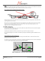
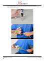
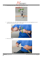
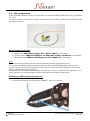
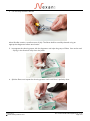
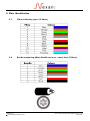
Installation Guide OPTICAL FIBRE CABLE MICRO-BUNDLE (MB) CABLE SUPPLEMENT January 2014 Nexans Cabling Solutions INSTALLATION GUIDE FOR OPTICAL FIBRE CABLE MICRO-BUNDLE (MB) CABLE SUPPLEMENT Table of Contents 1. Foreword ......................................................................................................................................... 2 2. Product references ......................................................................................................................... 3 3. Micro-Bundle OF cable pulling recommendations ................................................................... 4 3.1. About Intermediate Pulling ........................................................................................................... 5 4. Cable stripping ............................................................................................................................... 7 4.1. Cable Jacket removal process...................................................................................................... 8 4.2. Fibre preparation ......................................................................................................................... 12 4.3. Fibre termination .......................................................................................................................... 14 5. Fibre identification ....................................................................................................................... 15 5.1. Fibre numbering (up to 24 fibres).............................................................................................. 15 5.2. Bundle numbering (Micro-Bundle structure – more than 24 fibres) ...................................... 15 January 2014 Nexans Cabling Solutions 2014 Doc. N°:Micro Bundle cable supplement V0_11.doc Page 1/16 Important Note: I nstallation is to be pe rformed by qualifie d serv ice personnel 1. Foreword This document forms part of a series of documents related to optical fibre installation. Please see below for further information. This document provides specific information related to Micro-Bundle (MB) fibre cables. The General “Installation Guide For Optical Fibre Cable” document provides information related to key topics that need to be followed during installation. The following guides provide more detailed information on handling requirements for specific cable types: • Tight Buffer Cable Supplement • Loose Tube Cable Supplement • Micro-Bundle Cable Supplement (this document) • Pre-Terminated Cable Supplement In addition, there is also a General Installation guide (for both copper and fibre) which includes further information. Please note: The Nexans warranty may be invalidated if the cables have not been properly stored or handled according to Nexans Cabling Solutions (NCS) requirements. When logged into the NCS site, all these documents and also others relating to design and installation testing etc can be found here January 2014 Nexans Cabling Solutions 2014 Doc. N°:Micro Bundle cable supplement V0_11.doc Page 2/16 2. Product references The rules described in the following chapters are applicable to the following NCS OF cable ranges: LANmark-OF Micro-Bundle Indoor (N16x.MBINxx) LANmark-OF Micro-Bundle Universal (N16x.MBUNxx) January 2014 Nexans Cabling Solutions 2014 Doc. N°:Micro Bundle cable supplement V0_11.doc Page 3/16 3. Micro-Bundle OF cable pulling recommendations Important note In any fibre optic cable the load has be applied to the strength members of the cable (central strength element and glass/aramid yarns). Failure to lock the cable components together can lead to elongation of the jacket material which will cause irreparable damage to the fibres resulting in significant performance degradation. Remove approximately 200mm of the jacket and cut the internal elements as shown on the picture. To ensure that the pulling force will be applied on all the whole cable structure wrap the cable end with a strong adhesive tape to lock all the cable components together. Fix the cable to the pulling rope / tape using a specially designed pulling grip for optical fibre cable (length of 600mm minimum) to ensure that the pulling tension is well distributed on all cable components (outer sheath and reinforcing elements). Before termination, approximately 3m of cable should be cut off to remove any piece that may have suffered stress from the pulling tape or grip. January 2014 Nexans Cabling Solutions 2014 Doc. N°:Micro Bundle cable supplement V0_11.doc Page 4/16 3.1. About Intermediate Pulling In many installations the distance to be covered is short and the path is straight enough to allow the cable to be easily pulled (with a pulling grip correctly installed onto the cable end) without the need for intermediate pulling. However, on longer runs it may be necessary to pull the cable at intermediate points if the pulling force to be applied on the cable, to pull it in one go through the duct, would exceed the max pulling force allowed by the manufacturer. Important note about Micro-Bundle (MB) cable structure NEVER grab the outer sheath (jacket) of a MB cable when trying to pull cable out of a duct. If a cable is grabbed by hand, the point pressure that is applied in this manner may cause the outer sheath to be elongated as well as causing the fibres to be stretched. When the cable is then released, the optical fibres will then pull back and bunch up within the cable structure, which will cause irreparable damage to the fibres resulting in significant performance degradation. It is therefore imperative that the pulling load be applied to the strength members of the cable. For long runs the pulling operation must be accomplished in two or more stages. The pulling can be started at the middle of the run where a maintenance hole has been placed. The cable pulling will then be undertaken in both directions. The cable is first pulled through the duct in one direction (directly from the reel). Attention: when the end of a MB cable is coming out of the duct at the pull end, the operators have to continue to pull the necessary length of cable out of the maintenance hole by applying the force to the pulling grip, whatever the length of the cable to be pulled out. In no circumstances should the pulling force be applied directly onto the jacket of the cables as explained in the important note located at the beginning of this chapter. As a consequence we do not recommend using MB cable to create outdoor backbone links requiring several pulls to reach the full length of the path in one direction. The use of MB cable shall be limited to medium runs having just one intermediate maintenance hole. For pulling in stages the following configuration is not recommended for Micro-Bundle cable because of the force needed to be applied on the cable jacket at the intermediate stage. January 2014 Nexans Cabling Solutions 2014 Doc. N°:Micro Bundle cable supplement V0_11.doc Page 5/16 Configuration not recommended using Micro-Bundle cables The following method is however recommended. When the pull in the first direction is completed the remaining required cable shall be reeled off the drum and then placed on the ground in a figure of “8” pattern. Note Be sure to minimize the load on the cable by rotating the drum rather than just pulling on the cable itself and at all times respect the minimum bending radius of the cable. The end of the cable will be on the top of the figure of “8” so the cable roll must not be flipped over. The other end of the cable should then be pulled through the duct using the procedure described for the first end. It is not recommended to lay the cable directly on the ground. A protection layer should be installed to protect the cable as shown on the picture. January 2014 Nexans Cabling Solutions 2014 Doc. N°:Micro Bundle cable supplement V0_11.doc Page 6/16 Note When pulling cables through intermediate maintenance holes a continuous pull method is sometimes used with workers pulling the cable at different locations at the same time. This method cannot be applied to Micro-Bundle cable. Continuous pull method Pulling directly on the outer jacket with an excessive force will cause a compression of the fibre and create significant loss increase. This process can only be applied if the force to be applied on the cable by the hands of the workers does not cause any deformation of the outer jacket. That is the reason why the process is not applicable when installing MB cable structures. 4. Cable stripping For any fibre count or cable type, some of the cable outer jacket will have to be removed to expose the fibres for the termination process. Outside plant cables that will be terminated in trays need 2m of jacket removed. Recommended length are provided in the Nexans patch panel installation guides available from our website Micro-Bundle outer jacket stripping tool Micro-Bundle cable jackets can be removed using round cable slitters or other tools that will not damage the interior of the core. The Nexans recommended jacket stripping tool, adapted to MB cable structure, has been developed to cut the jacket longitudinally and around as shown here below. OGCL stripping tool - NCS part number: N890.131 January 2014 Nexans Cabling Solutions 2014 Doc. N°:Micro Bundle cable supplement V0_11.doc Page 7/16 4.1. Cable Jacket removal process We recommend removing lengths of maximum 1 metre. – Repeat the process for longer lengths. For a complete and detailed description of the process please refer to the OGCL tool user manual 1. Adjust the blade of the tool according to the thickness of the cable sheath Mark 2 for MB cables We recommend first testing the tool setting on a spare piece of cable 2. Set the tool in longitudinal cutting mode using D (pull + turn) January 2014 Nexans Cabling Solutions 2014 Doc. N°:Micro Bundle cable supplement V0_11.doc Page 8/16 3. Cut the jacket longitudinally using the part of the tool dedicated to this operation Note: the blade first has to be set into the right position to adjust the penetration into the jacket and then locked using E E January 2014 Nexans Cabling Solutions 2014 Doc. N°:Micro Bundle cable supplement V0_11.doc Page 9/16 4. Set the tool in the circular cutting mode using D (pull + turn) 5. Install the tool on the cable with the blade located at the end of the longitudinal cut and rotate the tool around the cable to cut the jacket 6. Remove the jacket January 2014 Nexans Cabling Solutions 2014 Doc. N°:Micro Bundle cable supplement V0_11.doc Page 10/16 7. Cut the central strength element and use the appropriate scissors to remove aramid or glass yarns January 2014 Nexans Cabling Solutions 2014 Doc. N°:Micro Bundle cable supplement V0_11.doc Page 11/16 4.2. Fibre preparation In Micro-Bundle cables the fibres are contained in an advanced flexible LSZH tube having a diameter of 1.3mm. The tubes contain a small amount of jelly. As a consequence the fibres need to be cleaned before the termination process. Recommended materials • • • Stripper tool (Multi-Wire stripper 821 - Ripley / Miller or equivalent) Low-lint paper (LANmark-OF Wipes for Anaerobic Toolkit – N102.226 or equivalent) Fibre degreaser (LANmark-OF degreaser 0,5l – N890.123 or equivalent) Note The recommended material has been selected according to their good performance. For instance the Nexans high performance degreaser is a natural biodegradable and non-toxic solvent that perfectly cleans the coated fibres but doesn’t remove the color of the fibre coating and doesn’t affect the fibre and its coating. An appropriate equivalent product could be used but the use of a non specific fibre degreaser is not recommended as it could damage the fibres and therefore invalidate the guarantee. Stripping and fibre preparation process 1. Insert the Micro-Bundle into the position 20AWG / .80 mm of the tool January 2014 Nexans Cabling Solutions 2014 Doc. N°:Micro Bundle cable supplement V0_11.doc Page 12/16 2. Cut and strip the Micro-Bundle Micro-Bundles contain a small amount of jelly. The fibres shall be carefully cleaned using an appropriate degreaser before termination. 3. Impregnate the cleaning paper with the degreaser and wipe the group of fibres from end to end – wiping in the direction away from the jacket 4. Split the fibres and repeat the cleaning process until each fibre is perfectly clean January 2014 Nexans Cabling Solutions 2014 Doc. N°:Micro Bundle cable supplement V0_11.doc Page 13/16 Perfectly clean fibres ready for termination 4.3. Fibre termination In Micro-Bundle cable structures the fibres are only protected by a 250µm coating. Direct termination with anaerobic field installable connectors is not recommended on these types of fibres. Pigtail splicing is preferred. Please refer to the pigtail splicing recommendations contained in the General “Installation Guide For Optical Fibre Cable” document. January 2014 Nexans Cabling Solutions 2014 Doc. N°:Micro Bundle cable supplement V0_11.doc Page 14/16 5. Fibre identification 5.1. Fibre numbering (up to 12 fibres) 5.2. Bundle numbering (Micro-Bundle structure – more than 12 fibres) January 2014 Nexans Cabling Solutions 2014 Doc. N°:Micro Bundle cable supplement V0_11.doc Page 15/16 Disclaimer This document is a guideline only. International and local procedures and safety standards must be observed and followed at all times. Nexans Cabling Systems will not be held liable for any damage or injury to personnel, equipment or business directly or indirectly as a result of using this document in part or in whole. The practices contained herein are designed as a guide for use by persons having the required technical skill at their own discretion and risk. The recommended practices are based on average conditions. Nexans does not guarantee any favourable results or assume any liability in connection with this document. Nexans does not assume any responsibility for the accuracy or completeness of this document. The user should review the information to ensure conformity to the current applicable codes and regulations and to the project requirements. Nexans reserves the right to change the technical specifications at any time without notice. Edition 08.01.2014 Copyright © Nexans 2014 All data subject to change without prior notice. January 2014 Nexans Cabling Solutions 2014 Doc. N°:Micro Bundle cable supplement V0_11.doc Page 16/16 © 2014 Nexans Cabling Solutions. All rights reserved. LANmark, LANsense and GG45 are registered trademarks of Nexans. www.nexans.com/LANsystems – [email protected] Nexans Cabling Solutions Belgium Alsembergsesteenweg 2, b3 B-1501 Buizingen Nexans Cabling Solutions UK and Intelligent Enterprise Solutions Competence Centre 2 Faraday Office Park - Faraday Road Basingstoke - Hampshire RG24 8QQ Nexans Cabling Solutions France 4-10, rue Mozart 92587 Clichy Cedex