1
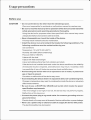
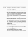
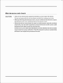
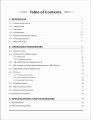
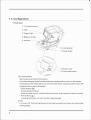
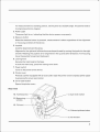
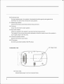
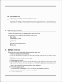
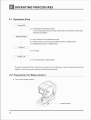
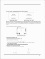
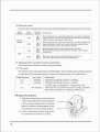
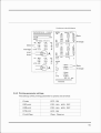
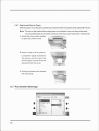
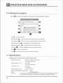
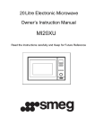
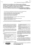
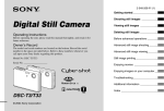
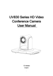
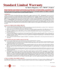
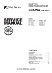
ser's
anua
Auto Ref/Keratometer GRK-8000
r
.,..,f,Cs
,
GRK-8000
)
•
•
Usage precautions
Before use
CAUTION
• Do not use th e device for other than the intended purpose.
We are not respons ible for acciden ts or malfunctions caused by careless u se.
• Be sure to read the manual prior to operation of the device to understand the
safety precautions and operating procedures thoroughly.
Us in g th e device for pu rposes other than specified in this manual may cause
unexpected malfunctions and/ or adverse events.
• Never disassemble nor touch the inside o f the device .
This may resu It in electric shock or malfunction .
• In stall th e device in an environment that meets the following conditions. The
following cond itions must be maintained during use .
Use conditions
Temperatu re : 10 to 35°C (50 to 95°F)
Humidity: 30 to 90o/o (Non-condensing)
Pressure: 800 to 1060 hPa
A place with low dust
A place with little externa l light
A level and stable surface free from vibration and shock
If the device is not instal led and used unde r the above cond itions , the re liabil ity
of measured results is impaired , and malfunction may resu lt. In addition , there
is a possibil ity of inju ry if the device receives shock and fa lls down.
• Avoid storing the device where it is exposed to ra in or water, or poisonous
gas or liquid is present.
Corrosion or malfunction of the device may occu r.
• Avoid installing the device where it is exposed to direct air-conditioning flow .
Changes in temperature may result in condensation inside the device or adversely
affect measu rements .
• Be sure to use a (HOS PITAL GRADE) wall outlet which meets the power
specification requirements .
If the line voltage is too high or too low, the device may not pe rform properly.
Malfunction or fire may occur.
• Connect the power plug to a ground outlet. Or connect a grounding wire to a
ground terminal.
Electric shock or fire may occur in the event of device malfunction or power leakage.
• Never use a power strip or extension cab le to supply the device with power.
The electrical safety may be lowered.
CAUTION
• Do not use a power cord other than the one provided . Also do not connect the
provided power cord to any other device.
Failure or fire may resu lt.
• Do not place heavy objects on the power cord.
The damaged power cord may cause fire or elect ric shock.
• Before connecting the cable, turn off th e power switch and disconnect the
power cord from the outlet.
Malfunction of the device may result.
• When the device is carried, two persons should hold it at t he f ront and the back
(both right and left sides) . Avoid lifting by the forehead rest or main body
instead hold it by the bottom of the base.
If only one person carries t he device, or areas other than th e base are used fo r
lifting and the device fa ll s, there is a possibility o f injury or malfunction.
• To transport the device, use the special packing materials to protect the device
from impact of dropping.
Excess ive vi bration o r impact to the device may ca u se malfunction.
• During installation and operation of the device , observe the following
instructions about EMC (electromagnetic compatibility) :
Do not use the device simultaneously wi t h other electronic equ ipmen t to avoid
electromagn eti c interfere nce w ith the operation o f the device.
Do not use the device nea r, o n, or unde r o t her electronic equi pment to avoid
electromagnet ic interference w ith t he operation of the device.
Do not use the device in t he same room with other equ ipment such as life-support
equ ipment, ot her equipment t hat has maj o r affects on th e lif e of the pa ti en t and
res ults of t reatment, or other measurement or treatment equipment that involves
small electric current.
Do not use the device s imultaneou sly with portable and mobile ra dio frequency
communication systems because it may have an adverse effect on operation of the
device.
Do not use cables and accessories that are not specif ied for t he device because
that may increase th e emission of electromagne tic waves fro m t he de vice or t he
system and decrease the immunity of the device to electromagnetic disturbance.
• The Electromagnetic Compatibility Directive sets the essential requirements
for electrical and electronic equipment that may disturb, or be disturbed by
Du ri ng use
CAUTI ON
other equipment. Follow the guidance in the tables for use of the device in an
electromagnetic environment.
• Before use, perform visual and operation checks. If abnormal conditions are
encountered , stop using the device .
If the device is used under abnormal conditions , intended results may not occur.
Also unexpected malfunctions or health hazards may occur due to improper
measurement.
• Before treating each patient, clean the patient's contact area (ch in rest and
foreh ead rest) w ith clean absorbent cotton or gauze dampened with rubbing
alcohol.
If chinrest paper is used, remove one piece for each patient.
For severe stains. \Yipe the area not with a dry cloth but with gauze dampened \Vith
alcohol.
• Keep the measuring window free of fingerprints and dust.
The measurement accuracy may decrease substantially.
• In the event of s moke or s trange odors, i mmediately turn off the device and
disconnect the power plug from the outlet. After you are sure that the smoke
has stopped, then contact u s or your authorized distributor.
Usage of the device under such abnormal conditions may cause fire or electric
shock. In case of fire, use a dry chemical (ABC) extinguisher to extinguish the fire.
• Immediately replace the power cord if the internal wires are exposed, the device
turns on or off when the power cord is moved, or the cord and/or plug are too hot
to be held w ith hands.
This may result in electric shock or fire.
In the event of malfunction, disconnect the power cord from the 'vall outlet. Never
touch the inside of the device.
• Never press on the LCD with a hard object s uch as a ball-point pen . Keep
magnetic objects away from the LCD.
The device may be damaged.
• Do not operate the LCD with wet hands.
Water seeping into the device may result in failure of the device.
• There may be a few dead or constantly-l it pixe ls in your LCD. Th is does not
represent failure of the LCD; This is due to the structure of the LCD.
CAUTION
• This device has been tested and found to comply with the limits for medical
devices to the IEC 6060 1-1-2: 2001/ am1: 2004, and Medical Device Directive
93/42/EEC .
These limits are designed to provide reasonable protection against harmful
interference i n a standard medical installation.
This device generates, uses and can radiate radio frequency energy and, if
not installed and used in accordance with the i nstructions, may cause harmful
interference to other devices in the vicinity.
However, there is no guarantee that interference will not occur in a particular
installation. If this device does cause harmful interference to other devices,
which can be determined by turning the device off and o n, the user is encouraged
to try to correct the interference by one or more of the following measures :
If this device does cause harmful interference to other devices, which can be
determined by turning the device off and on, the user Is encouraged to try to
correct the interference by one or more of the following measures:
Reorient or relocate the receiving device.
Increase the separation bel\veen the devices.
Connect the device to an outlet on a circuit different from that to \vhich the other
device(s) are connected .
Consult the manufacturer or field service technician for help.
• The device is Class A (CISPR1 1 cla ssification). It is allowed in domestic
establishments when used under jur isdiction of a health care professional.
• Never use the device with cables or accessories other than the designated ones.
Malfunct ion caused by i mproper electromagnetic compatibility (E MC)
characteristics may result.
• Never use portable o r mobile radio frequency (RF) devices in the vicinity of
this device.
These devices may adversely affect medical electrical equipment and malfunction
may result.
After use
CAUTION
• This device uses a heat-sensitive pri nter paper. To keep the printed data for
a long period of time, make copies of the printouts.
The paper degrades over t ime and the printed data may become illegible.
• W h en the device is not in use, turn off the power switch and put the dustcover
over the device.
If not, dust may affect the measurement accuracy.
• Do not yank the power cord to d isconnect it from a wall outlet but hold the plug.
This can damage the metal core of the cord and may re sult in fire, short c ircuit or
electric shock.
• Occasionally c lean the prongs of the main plug with a dry c loth.
If dust settles between the prongs, the dust will collect moisture, and short circuit
or f ire may occur.
• If the device wi ll not be used f or a long time, disconnect the powe r cord from
the wall outlet.
Fire may occur.
• Maintain t he surrounding temperature and humid ity in the fo llowing ra n ges
during transport and storage of the devi ce.
Environmental conditions
Temperature: - 10 to 55°C ( 14 to 131°F)
Humid ity: 10 to 95o/o (non-condensing)
Atmospheric pressure: 700 to 1060 hPa
A place with low dust
A place not exposed to direct sunlight
• W h en transporting, pack the main body in the original packing material with
the fixing leve r u nlocked.
Excessive vibration or impact may cause device malfunction.
Maintenance and check
CAUTION
• Only service technicians properly trained by us can repair the device.
We are not re sponsible for any accidents resulted from improper servic ing.
• When performing maintenance work, secure sufficient maintenance space.
Maintenance work in an insufficient space may result in inj ury.
• When the device is sent back for repair or maintenance, wipe the surfaces
(especially, the area where patients contact) of the device with a clean cloth
dampened with ethyl alcohol for disinfection.
Contact us or your authorized distributor to check whether the device needs
measurement accuracy calibration if the AR -measured results are substantially
different from subjectively measured results.
Table of Contents
1. BEFORE USE ................................................................................................................................ 1
1.1
Outline of the Device
1
1 .2
Intended Use
1
1 .3
Principles
1
1 .4
Configuration
2
1 .5
Measuremen t Screen Layout
5
1 .6
Checking Contents
7
1 .7
Before First Use
7
2. OPERATING PROCEDURES ·················· ···························· ........................................ a
2 .1
Operation Flow
8
2.2
Preparation for Measurement
8
2.2. 1 Sleep mod e
11
2.2.2. Fini sh measuremen t
11
2.3
AR (refractive e rror) Measuremen ts
2.4
KM (corneal curvature rad ius) Measurement. (KER Series)
2.5
SIZE Measurement. (KER Series)
2.6
Printing
2.6.1 Printing measured data
2.6.2 Print ing parameter settings
12
13
13
14
2.6.3 Repla cing Printer Paper
14
15
2.7
Parameter tables
16
2.8
Main Parameter tables
17
2.9
Settin g the date and time
17
2.1 O Setting the company
18
3. SPECIFICATIONS AND ACCESSORIES ............................................................. 13
3. 1 Specifications
18
3.2 Standard Configu ration
19
BEFORE USE
1.1 Outline of the Device
T h e device wh ich objecti vely measures refractive erro rs of sphere , cylinde r, and axis.
Refraction is ma i nly performed as a reference for lens prescription to correct the visua l
acu ity using glasses or contact lenses.
This device is a single unit with the main body mounted on a base. The base is provided with
a ch in res t on the patient side and an LCD panel , operating buttons, joystick, and prin ter to
fac il itate alignment and other operations.
The device offers the following features in add ition to the above features:
• The device is provided w ith an auto tracking mechanism that ach ieves alignment in the
up-and-down direction .
• An auto shot funct ion is provided; measurements to be taken automatically when the
device is best aligned and in focus .
• A motorized up-and-down ch inrest allows the operator to easily adjust the height of t he
chin rest.
• Printer has a paper auto-cut feature.
1.2 Intended Use
T h e Au to Re fr acto met er is a d iagnostic device tha t is indicated for use in th e automated
measurement of refract ive errors of the eye .
Th e Auto-Re f / Keratometer is a medica l appliance which performs measurement of the
refract ive errors of the eye and corneal radius of curvature.
1.3 Principles
F ine measurement beams are projected on the f und us of the pa t ient' s eye by a projecting
optical system and t h en computation is pe rformed by captu rin g t he reflected beams as a
ring image to measu re the refractive errors (SPH, CYL, and AX IS) of the patient's eye.
1
1.4 Configuration
Fro nt v iew
1, Function buttons
2. LCD
3. Power Light
4 . Measure button
6. Locking lever
7. Power switch
8. Printer cover
9. Cover open button
1.Function buttons
Set the device and switch the screen.
Functions assigned to the funct ion buttons are displayed by icons on the screen.
Two buttons in the lower left corner of the screen have unique functions when the
measurement screen is displayed.
• Clear button ( ' ' )
Erases measured data.
When the clear button is held for about a second , all the measured data is erased.
• Print button ( ~ )
Pressing this button can print out the measured data.
2. LCD
5.7-inch LCD. Pu lling the bottom of the disp lay panel provides an adjustab le
viewing angle.
2
For measurement in a standing posture, set the panel at a suitable angle. The panel is reset to
its original position by magnet.
3. Power Light
The power light is on , indicating that the device powers on properly.
4. Measu re button
When the measure button is pressed, measurement is taken regard less of the alignment
or focusing condition of the device.
5. Joystick
Used fo r alignment and focusing.
Alignment in the right and left directions can be performed by moving the joystick to the right
and left. Rotating the joystick is fo r alignment in the up and down directions. For focusing,
move the joystick forward and backward.
6. Locking lever
Secures the main body to the base.
To lock the main body, press the locking lever down.
7. Power switch
Turns on the power to the device .
8. Printer cover
Protects a printer equipped with an auto cutter. Open the printer cover to rep lace printer paper
by pressing the cover open button.
9. Cover open button
Opens the printer cover.•
Rear view
10. Forehead rest
13. Eye level marker
11. Measuring --+,~--'"-'i
window
14. Chinrest up/down button
3
10. Forehead rest
During measu rement, the patient's forehead should be gently rest against the
forehead rest.Clean the chin rest for each patient.
11 . Measuring window
Check the window clean li ness before measu rement.
12. Chinrest
Clean the chin rest for each patient.
13. Eye level marker
Used as a guide for the patient's eye level during measurement.
The height of t he chinrest should be adjusted so that the center level of t he patient' s
eye roughly aligns with this line.
14. Chinrest up/ down button
Moves the chin rest up or down .
15. PD window
An LED is provided to detect the PD value.
16. Power inlet
Underside view
-•
•
16. Power inlet
Adetachable power cord is connected here .
4
1.5 Measurement Screen Layout
19.Auto
17. Measure
mode
20. Auto
1. Patient' s eye
2. Reset button
3. Fundus circ le ---+---"'--t-4. Circle display
button
5. Ch inrest limit
,
--1---1
...
...
6. Auto tracking - - - - -·
button
7. History button
I
18. VD
15. Focusi ng ind icator
VD
14. Menu button
,'--,...
ff
f' ,,
\
1
s -4.50
c -0.50
69
A
8. Measured
values
16. CYL mode
\
I
.... __ ..., /
R 2
R1 7.62
R2 7.62
AA
0
pl
,
13. Measuring window
~
limit
12. Measure mode button
L 2
s -5.25
c -0.75
A 147
10. Print button
9. PD
1. Patient's eye
Indicates the right or left eye of the patient.
2 . Reset button ( ' ' )
Rest the device to initial state.
3. Fund us circle
After a measurement, you can observe the stored retina image by pressing the circle
display key .If the i mage is an i ncomplete circ le , the measurement is not re li ab le,
and should be made once again . Incomplete retina images may be caused by eye blinking
or by eye movement. Sometimes it is because the signal reflected from the retina is too
weak, or the pupil diameter is less than 2.0mm, or the dust in the surface of the lens .
4 . Circle display button
After pressing measu rement key, a window will popup on the left upper LCD, Eyeg roud
parameter im age cycle measured by instrument disp lays , which is used to judge the
valid ity of measurement .Pressing the key again ,it will close the window.
5. Chin rest limit
When the chin rest is at the upper (or lower) mechanica l lim it, the upper limit ind icator
( ~ )or lower limit indicator(~ ) is displayed on the screen.
5
6. Auto tracking button
Selects the auto tracking function.
7. History button
Show the all measurements
8. Measured values
Displays the latest measured results.
9 PD
10 . Print button
Print the measured results
11.CYL mode button
Switches cylinder mode.
CYL-
Ind icates cylindrical power by - read ing.
CYL+ Indicates cylindrical power by+ read ing .
CYL+ Cylinder data is indicated by+ reading when the refractive error is positive for any
axis angle. Indicates the cylindrical power by - read ing in other cases .
Cylinder mode can be switched even after measurement.
Data is printed out with the mode status at the time of printing.
12. Measure mode button (KER Series)
Select the mode of REF . KER . R &K . SIZE .
13. Measuring window limit
When the measuring window at the upper (or lower) mechanica l li mit, the uppe r lim it
indicator ( ;
y
) or lower limit indicator ( ~ )is displayed on the screen .
A
14. Menu button
Set parameters, date and time, and enter comments.
15. Focusing indicator
Indicates the distance between the main body and the patient's eye.
Operate the joystick until t he optimum condition is displayed.
16. CYL mode
Represents the selected cylinder mode.
17. Measure mode
Represents the selected cylinder mode.
18 . VD
Represents the selected VD value.
6
19. Auto measure icon
Represents the setting of the auto measure function.
20. Auto t rack ing i con
Represents the setting of the auto tracking function (alignment in the up , down directions).
1.6 Checking Contents
Unpack the contents from the shipping carton and check them.
The fo llowing are included in the standard configuration.
·Main body
•Printer paper (2 rolls)
•Power cord
·Dust cover
•Operator's manual (this book)
•Model eye
1. 7 Before First Use
Place the device on a stable table and connect the power cord.
1 Place the main body to a stable table.
2 Lock the main body to the base unit with the locking lever and lay the device down
gently.
3 Connect the power cord to the power inlet.
4 Stand the device upright.
5 Confirm that the power switch is turned OFF and plug the power cord into a wall outlet
(Be sure to use an outlet equipped with a ground terminal , E lectric shock or fire may
occur in the event of device malfunction or power leakage).
6 Turn ON the power switch.
The initial screen is displayed on the LCD and the device starts initializing.
7 Confirm that the measurement screen is displayed.
8 Load the printer paper.
7
] OPERATING PROCEDURES
2 .1 Operation Flow
Power ON
2.2 Preparation for Measurement
Turn on the power switch and set measurement conditions if necessary.
Prepare the patient.
Measurement
2.3 AR (refractive error) Measurements
2.4 KM (cornea l curvature radius) Measurement. (KER Series)
2.5 SIZE Measurement. (KER Series)
Printing
2.6 Printing
Power off
2.2.3 Finishing the measurement
•
* For lens prescri ption for correction of visual acuity of g lasses o r such , subjectively test the
patient's visual acuity with reference to AR-measured data.
2.2 Preparation for Measurement
1 Turn on the power switch .
8
The in itial screen is displayed and the device is initialized.
AUTO
AUTO
Refractometer
Ref/ Keratometer
Ccpyr lghl 2011.2012 Ver 1.7 1
Auto Refraclome ter
Copyrlght 201t·2012Ver 1.21
Initial screen (REF)
Initial screen (REF/ KER)
Auto Ref&Keratome ter
Wait fo r a while until the screen is switched to the measurement screen. When the power to
the device is turned on , the main body makes small right/left movements in order to determine
the initial setting position for auto tracki ng. Thi s does not mean that the device has been
broken.
2 The measurement screen is d isplayed .
,,
!Bl
0
~
•
•A•
•
-
·····..,.
.,..-+
"·.....·
0
;
CV\.
R
• s o.oo
c 0 .00
A
0 PO
L
s
0. 00 ....
0 .00
A
0
c
Measurement screen
3 Perform checks before use
Perform the following checks before use.
No error message is displayed .
The main body moves smoothly using the joystick.
The chinrest moves up and down by pressing the chinrest up/down button.
Printer supply is adequate.
The measurement accuracy satisfies the specifications .
4 Establish measu rement conditions .
The following cond itions should be specified:
. . ..
......
..
.
+
. ...
..... .
No Focus
Focus
..
.
.. .
9
1: Measu re mode
Press the auto tracking button to select auto tracking and select the auto measure on the menu.
Auto
tracking
Auto
measure
Screen
display
Description
ON
m
~
Auto tracking in the up-and-down directions is turned on. Manually
align the device in the left-and-right.Measurement starts automatically
when t he eye is best aligned and focused .
OFF
m
[OFF)
Auto tracking in the up-and-down directions is turned on.Manually
align the device in the left-and -right and bring the eye into focus.
Press the measure button to start measurement.
w
~
Manually align the device and bring the eye into focus.
Measurement starts automatically when the eye is best al igned
and focused.
w
[OFF)
Manually align the device and bring the eye into focus .
Press the measure button to start measurement.
Up and
Down
ON
OF F
OFF
2: Measu rement conditions set by parameters
Various device conditions can be set by parameters.
3: CYL mode
The cylinder mode, reading direction of cylinder data in which cylinder data (cylindrical power)
is represented du ring measurement is selected by pressing the CYL mode button .
Screen display
CYLmode
Description
CYL-
- read ing
Indicates cylindrical power by+ read ing.
CYL+
+reading
Indicates cylindrical power by - reading.
CYL ±
Mix reading
Cylinder data is indicated by+ readi ng when the
refractive erro r is positive fo r any axis angle. Ind icates
the cylindrical power by - reading in other cases.
5 Prepare the patient_
1) W ipe the fo rehead rest and chin rest that
contact the patient with clean absorbent
cotton or gauze dampened with rubbi ng
alcohol. If a stack of chinrest paper is fixed
on the chinrest, remove one sheet of paper.
2) Instruct the patient to take off glasses
or contact lenses and sit on a chair.
10
Chinrest ---'<;"\""~~
3) Have the patient place his/her ch in on the chin rest as deeply as possible, and his/her
forehead on the forehead rest lightly.
4) Adjust the height of the ch inrest by pressing the chin rest up/down button until the center
level of the patient's eye aligns with the eye level marker. Before adjusting the height of
the ch inrest, let the patient know that the chin rest moves up and down.
When the chinrest is at the upper (or lower) mechanica l lim it, the upper limit indicator
(or lower lim it indicator) is displayed on the scree n.
6 Start measu reme nt.
See "2.3 AR (refractive error) Measurements" for details of measu re ments .
Instruct the patient not to blink during measurement. Additionally, instruct the patient not to
bli nk or open his/her eyes Immediately before measurement to avoid measurement fail ure .
Instruct the patient to keep both eyes wide open during measurement. Closing one eye may
cause an unstable fi xation and the other eye may not open wide.
7 Print the measured results.
Printing operation varies accord ing to the parameter setting.
2.2.1 Sleep mode
The device goes into sleep mode automatically to save power if no operation is performed
for a certain period of time. The time that the device goes into sleep mode can be selected
from 5 minutes, 15 minutes, or NO (no sleep mode) (factory setting: 5 minutes).
Sleep mode places the device into the following conditions:
• The LCD goes off.
The working status LED bli nks.
• LCD has been in screen protection always
The working status LED bli nks.
The device recovers to normal mode from sleep mode by the following methods:
· Press any button.
· Man ipu late the joystick to move the base R or L.
2.2.2 Finishing the measurement
1 To finish the measurement, t urn off t he power switch. It is allowed to turn off the power
w ith any screen displayed.
2 Check the measuring window and clean the lens if necessary.
3 Clean the forehead rest and chin rest , and put the supplied dust cover on the device.
Always keep them clean for the next use.
11
2.3 AR (refractive error) Measurements
1 Instruct the patient to: " Look through the measuring window. As you will see the
picture, watch the c enter of it without straining''.
2 Manipulate the joystick to display the patient' s eye on the screen.
By moving the j oyst ick laterally, the main body moves ri ght, left , forward and backward .
By tu rning the upper part of the joystick, the main body moves up and down. Align the eye
posi ti on t o the measuring point w ith right , left , up and down movem ents. Adjust the fo cu s
w ith forward and backward movements.
3 Perform alignment and focusing
The methods of alignment and focusing vary according to the settings of the auto tracki ng
and auto shot.
Up-and-down auto tracking
1) Perform rou gh a lignment and focus ing by mani pul a tin g th e joystick to place in the
working range of auto t racking .
2) When the device is placed wi thin the worki ng range of auto track ing, it automati cally
starts alignment in the up-and-down direction.
3) Manipulate the j oystick to move the mire ring reflected on the pa t ient's eye with in the
target.
Auto track ing OFF
1) Manipulate the j oyst ick to perform rough alignment and fo cu sing .
2) As the f ocu sing indicator is d i sp layed, manipulate the j oys ti ck until the optimum
focus ing ind ica tor is displayed. During t he foc using, maintain alignment between the
device and the patient's eye.
When main body is not within the working range of auto tracking :
As t he limit indicator is displayed , mani pulate the j oys ti ck or chinres t up/down button in
the direction o f the arrows.
Move t he chin rest up.
Move the chinrest down.
4 Measurement starts .
Measurements are taken automatically when the device is best aligned and focuse d on the
eye (when the auto measure fu nction is turned on) .
When the auto measure function is turned off , press the start button to start measurement
5 Measurement completes.
When the specified num ber of A R measu rements is performed and the data is stable (no.
12
variations)the measurement automatically completes.
6 Meas ure th e other eye i n th e sa me manner.
When the eye to be measured is swi tched, the measuring unit returns to t he orig in in the
forward-and-backward and side-to-side directions .
7 Let the patient know that the measurement is completed and instruct him or her to rest
comfortably.
8 Print the measured results.
2.4 KM (corneal curvature radius) Measurement. (KER Series)
Preferences: mm, D, AVG.
Mm: the horizontal and vertical corneal radius
D : the horizontal and vert ical corneal diopter
AVG : the average of corneal radius
1. For the Keratometer measurement mode1, please refer to the same procedures of 2.3
2. For the Ref& Keratomer measurement mode, please refer to the same procedures of 2.3
2.5 SIZE Measurement. (KER Series)
Press" @"button to select Size main interface .Press"
0
1
" button to enter corneal rad ius
measu rement interface, please to the lower right diagram.
,,
Ill)
I I
I :!!" IOfFIW t2 ISIZEA
I
0
•
SIZE main
measurement interface
Corneal radius
measurement interface
13
2.6 Printing
2.6.1 P rinting measured data
Measured data is printed out by pressing the print button after measu rement.
(Sample printout)
..,,..~v~~~~'-°"""'"~
. DATE :2012-05- 8
Company
Add
Name
VD
Righ t
11 :08 :08 -+-- Date and time
XXXXXXXXXXXXXXXX
-
xxxxxxxxxxxxxxxx
l NAME :
I VD=l 2 mrn
j_R
s.
M/F
c
A
70
Sphere
Cylinder
- >
Left
L
-0 .25
69
-3.25
-0 .25
70
-3 .25
-0 .25
70 ~-
c
s
Results of Right-eye
(last 3 results is printed)
Ave rage
A
90
92
91
Axis
Pupil distance
->
_J_
PD :
63
91 -+-- Average
1nrn
xxxxxxxxxxxxxxx
Manufacturer
Model
-0 .25
Results of Left-eye
(last 3 results is printed)
I
XX:XXXX
L.~. .- --A)'<~ ~·~
.....
.........,..,,._
VD: vertex distance f rom lens to cornea.
PD: D istance between two pupils
14
Continuous to the left diagram
DATE:2012-0 5- 8
I 1:08 :08
xxxxxxxxxxxxxxxx
xxxxxxxxxxxxxxxx
NAME:
lvl/F
[REF]
Data
Average
VD• l 2mm
<R> SPH
-3.25
~ -3.00
-3.25
- AVG -3 .25
-
,,,
EY E
Print
CYL(+/- )
C YL
-0.25
-0.25
-0.25
-0.25
l>
I
'
<L>
SPH
- 4.00
-4.00
AVG -4.00
,,
-'
AX
70
69
70
70
A
[KER]
<R>
RI
7.76
1.15
7. 74
mm
RI
7.75
R2
7.73
Index 1.33 75
R2
AX
7. 73
135 ,
7. 74
135
7. 73
I 36 •
D
AX
43.56
135
4 3.60
45
Data
Average
- - - - - - - -- - - - - -- - -- - - - - - - - - - - - -- -- - - J
AVG 7.74
CYL
<L>
RI
7.75
7.75
7.73
mm
RI
7.72
R2
7.73
43 .5 8
0
R2
7 .74
7 .74
7.73
D
43.69
4 3.65
0
AX
134
135
134
AX
134
44
----------------------------------CYL
-0.25
-0.25
-0.2 5
AX
90
92
91
' A
AVG 7.72
C YL
(SIZE]
<R >
I.
2:
AVG
<L>
I:
2·
AVG
43 .67
0
7.58mm
4.78mm
6. I 8mm
0
Data
-
7.53mm
4 .83mm
6. 18mm
PD: 63
Average
mm
xxxxxxxxxxxxxxx
xxxxxx
2.6.2 P r i nting p aramete r se t ti n gs
Th e settings o f the prin t ing parameter's options are as follow:
Printer
OFF, O N
REF print
STD, ALL, AVG, OFF
K ER pri nt
STD, ALL, AVG, OFF
EYE print
OFF, O N
Print& Clear
Clear, Reserve
15
2.6.3 Replac in g Printer Paper
When the paper is running short, please stop using the printer and replace printer paperwith new one.
Note : Do not run the printer when printer paper is not loaded. It may ruin the printer head.
Do not pull the paper in the printer forcefully. This may cause malfunction of the printer.
1. Press the cover open button
to open the printer cover.
2. Insert new printer paper.
Load printer paper as shown in
the picture on the righ t. Set
printer paper so that its end is
exposed from the cover.
- ~-
3. Push the printer cover toward
I •
the main body.
2. 7 Parameter Settings
Item Time Corp . RS-232
j
Screen sa ve
Step
Pr inter
CVL
PD
Drrm •
12rrm
13. 75
15mm
.....
~~
=·==R=EF=p=r=i =nt==============·::l~
16
2.8 Main Parameters Settings
Tit le
Opt io n
VD
Omm, 12mm . 13.75 mm , 15mm
Screen saver
Disabled,5min -> OFF,5min ->ON, 15min ->OFF, 15min ->ON
Step
0. 12D ' 0.25 D
Printer
CYL
OFF. ON
+/-, +,-
PD
OFF,ON
REF Print
STD ,ALL ,AVG ,OFF
M.Speed
HIGH ,MID ,LOW
M.Mode
REF , KER , R&K ,SIZE
K.lndex
1.3375 ' 1.336 ' 1.332
KER Pri nt
STD ,ALL ,AVG ,OFF
EYE Print
OFF .ON
KER INC
mm , D ,AVG
R&K Disp
Left, M id
M.Auto
OFF , Auto
Print&Clear
Clear, Reserve
Astigmatism
AUTO lift
+ '
OFF, Auto
Brightness
1 , 2 , 3 , 4 ,5
Note : Options in bold font style a re factory defaults.
Choose the paramete r you need according to the arrow direction , then press~ or
iii the parameters
can be saved. Other keys don't work.
2.9 Setti ng the date and time
Press ~ to enter the interface of time setting, setting the date and time ..
•
t
T
m
Item Time Corp. RS-232
-
Date
Time
I
I ..,
"' ..
~
6.
I
2:
9
Move the
and pressor +
press ~ o r
or
arrow to the item
to -
iii
adjust the data,
to save data.
17
"'"'"--":i
SPECIFICATIONS AND ACCESSORIES
2.10 Setting the company
Press ~ to enter the interface of company setting, setting the company
Item Time Corp.RS-232
Corp
r-~~~~~~~~~~~
Add r
Dl234567B9ABCDEFGHI
JKLlvV-JOPQRSTUV\'IXYZabc
de fghijk lmnopqrs tuvw
xyz=- _@$ #&*.• : ;A%Cl !
+r
+
shift ~ : Company/ address
-
Entry Left-click
r : Current entry moves towards left by one character.
Entry Right-click+f : Current entry moves towards right by one character.
Characters Left-click
: Characters box moves to left by one.
Characters right-click . . : Characters box moves right by one
Line Feed
Save
Exit
0 : Cursor i n characters box moves down by one line.
iii : Save the settings data.
~
: Save data and exit to the measurement interface.
3.1 Specifications
Measurement of refractive error (AR measurement)
Spherical power (S)
-20.00 to +20.000 ( V0 = 12mm)
0.12/ 0.250 increments
Cylindrical power
(c )
Oto ± 100
0.12/0.250 increments
o· to1 so·
Cylinder axis (A)
1°increments
Vertex distance
(vo)
0, 12,13.75,15mm
Minimum pupil d iameter measurable
Chart
Accuracy
18
¢ 2mm
Auto fogg ing system
The accuracy specifications are based on the results of eye model test ing pe rformed
in accordance with IS010342, Ophthalmic Instruments - Eye Refractometers.
Item
Measurement range
Step
Tolerance
Spherical (S)
-20.00- +20.00D
0 . 12/0.25D
0 - :!: 10.000: :!: 0 .25D
:!: 10.00 - :!: 20.00D: :!: 0.50D
Cylindrical (C)
-10.00 -+1 0 .00D
0 . 12/0. 25D
:t 0.25D
Axis (AX)
0 -1 80 °
1•
3•
KM (corneal curvature radius) Measurement.(KER Series)
Ker. index (K.index)
1.3375, 1.336, 1.332
Rad ius of Curvature
5 .0 to1 O.OOmm
0 .01mm increments
33.00 to 67.50
0.12/0.250 increments
2.00 to 14.00mm
0.01mm increments
Corneal Power
Corneal Diameter
PO measurement
Measuremen t range
40to 85 mm
1.00mm increments
Movable range of horizontal direction (by joystick)
Forward and backward 36 mm
Right and left
85 mm
Working range of auto trac k ing
Up and down
±16mm
Other functions
Auto shot
Display
Printer
Dimensions and weight
Dimensions
Weight
Power source
Power consumption
Measurement starts automatically when the device is best aligned and focused .
5. 7-inch color LCD
Thermal line printer with auto cutter
Width 58 mm
480 ( L) X 270 (W) X 445 (H)mm
17kg
AC1OO - AC240V±10%50/ 60Hz
100VA
Environmental conditions (du r ing use)
Temperature
10 to 35 °C (50 to 95°F)
Humidity
30 to 90°/o
Pressure Atmospheric pressure 800 to 1060 hPa
3. 2 Standard accessories
Main body
Printer paper
Power cord
Dusts cover
Operator's manual
1 unit
2 rolls
1 unit
1 unit
1 volume
Note: Text in this manual is subject to changes without notice.
19