1
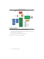
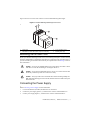
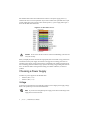
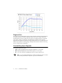
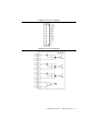
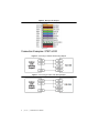
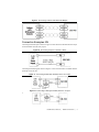
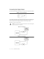
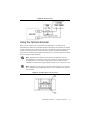
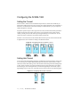
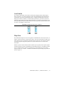
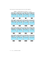
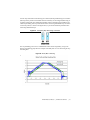
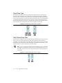
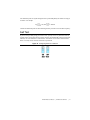
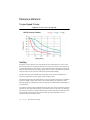
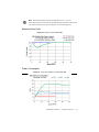
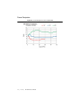
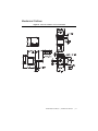
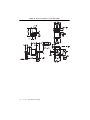
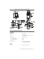
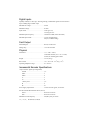
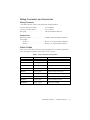
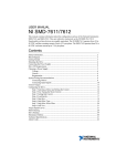
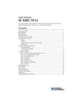
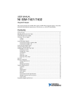
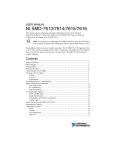
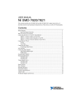
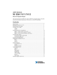
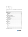
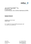
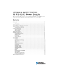
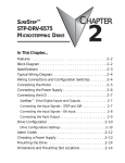
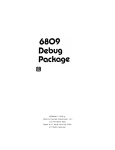
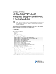
USER MANUAL NI ISM-7400 Integrated Stepper This manual describes the NI ISM-7400 integrated stepper. It describes electrical and mechanical characteristics of the devices, as well as I/O functionality. Contents Getting Started.......................................................................................................................... 2 Mounting the NI ISM-7400 ...................................................................................................... 3 Connecting the Power Supply .................................................................................................. 3 Choosing a Power Supply......................................................................................................... 4 Voltage.............................................................................................................................. 4 Current .............................................................................................................................. 5 Regeneration..................................................................................................................... 6 Connecting Input Signals.......................................................................................................... 6 Connection Examples: STEP & DIR................................................................................ 8 Connection Examples: EN................................................................................................ 9 Connecting the Digital Output.................................................................................................. 10 Using the Optional Encoder ..................................................................................................... 11 Configuring the NI ISM-7400 .................................................................................................. 12 Setting the Current............................................................................................................ 12 Setting Idle Current .......................................................................................................... 12 Load Inertia....................................................................................................................... 13 Step Size ........................................................................................................................... 13 Step Pulse Type ................................................................................................................ 16 Step Pulse Noise Filter ..................................................................................................... 16 Self Test .................................................................................................................................... 17 Reference Materials .................................................................................................................. 18 Torque-Speed Curves ....................................................................................................... 18 Heating.............................................................................................................................. 18 Mechanical Outlines ......................................................................................................... 21 Technical Specifications........................................................................................................... 23 Amplifier .......................................................................................................................... 23 Motor ................................................................................................................................ 23 Digital Inputs .................................................................................................................... 24 Fault Output...................................................................................................................... 24 Physical............................................................................................................................. 24 Incremental Encoder Specifications ................................................................................. 24 Mating Connectors and Accessories................................................................................. 25 Alarm Codes ..................................................................................................................... 25 Worldwide Support and Services ............................................................................................. 26 Figure 1. Block Diagram Getting Started You will need the following items to get started with your NI ISM-7400: 12 VDC to 48 VDC power supply. NI PS-12 (NI part number 748906-01) or NI PS-13 (NI part number 748907-01) recommended. Source of step signals, such as a PLC or motion controller. Refer to Choosing a Power Supply for more information. 2 | ni.com | NI ISM-7400 User Manual Figure 2 shows an overview of the connectors on the NI ISM-7400 integrated stepper. Figure 2. NI ISM-7400 Integrated Stepper Connectors 2 1 3 4 1 2 Status LED DIP Switches (current, idle current, steps/rev, load inertia) 3 4 Power and I/O Connector Mounting Holes (x4) Mounting the NI ISM-7400 Mount your NI ISM-7400 using four M3 screws, the mounting hole depth is 4.5 mm. Securely fasten the NI ISM-7400 to a smooth, flat metal surface to conduct heat away from the motor. To prevent overheating, forced airflow from a fan may be required. Refer to the Heating section for more information. Caution Never use your NI ISM-7400 in a space where there is no airflow or where other devices cause the surrounding air to be higher than 40 °C. Caution Never put the NI ISM-7400 where it can get wet or where metal or other electrically conductive particles can contact the circuitry. Always provide air flow around the drive. When mounting multiple NI ISM-7400 integrated steppers near each other, maintain at least one half inch of space between devices. Caution Connecting the Power Supply Refer to Choosing a Power Supply for more information. 1. Use 0.65 mm diameter (22 AWG) stranded wire for connections. 2. Connect the power supply positive (+) terminal to the connector terminal labeled V+. 3. Connect power supply negative (-) terminal to the connector terminal labeled V-. NI ISM-7400 User Manual | © National Instruments | 3 The NI ISM-7400 contains an internal fuse that connects to the power supply positive (+) terminal. This fuse is not user-replaceable. If you want to install a user-replaceable fuse in your system, install a fast acting 2 A fuse in line with the positive (+) power supply lead. Figure 3 shows the NI ISM-7400 connections. Figure 3. NI ISM-7400 Connector Do not reverse the wires. Reverse connection will damage your drive and void your warranty. Caution When you rapidly decelerate a load from a high speed, much of the kinetic energy of that load transfers back to the power supply. This transfer can trigger the overvoltage protection of a switching power supply, causing it to shut down. Unregulated power supplies generally do not have overvoltage protection and have large capacitors for storing energy coming back from the drive. NI offers the SMD-7700 regeneration clamp, part number 748908-01, to solve this problem. Choosing a Power Supply NI offers two power supplies for the NI ISM-7400: • NI PS-12 (24 V, 6.3 A) • NI PS-13 (48 V, 6.7 A) Voltage Your motor can provide more torque at higher speeds if you use a higher power supply voltage. Refer to the speed-torque curves for more information. If you choose an unregulated power supply, ensure the no-load voltage of the supply does not exceed 50 VDC. Note 4 | ni.com | NI ISM-7400 User Manual Current The following charts list the maximum current required for each motor at several common power supply voltages. NI ISM-7400 User Manual | © National Instruments | 5 Regeneration If you plan to use a regulated power supply you may encounter a problem with regeneration. If you rapidly decelerate a load from a high speed, much of the kinetic energy of that load is transferred back to the power supply. This can trip the overvoltage protection of a switching power supply, causing it to shut down. Unregulated power supplies are better suited for applications with significant regeneration as they generally do not have overvoltage protection and have large capacitors for storing energy coming back from the drive. Refer to Connecting the Power Supply for more information. Connecting Input Signals The NI ISM-7400 has three inputs: • STEP—High-speed digital input for step pulse commands, 5 V to 24 V logic • DIR—High-speed digital input for the direction signal, 5 V to 24 V logic • EN—5 V to 24 V input for commanding the removal of power from the motor To convert STEP and DIR inputs to STEP CW and STEP CCW, move switch #8 to the ON position. Refer to Step Pulse Type for more information. Note 6 | ni.com | NI ISM-7400 User Manual Figure 4. Connector Pin Diagram Figure 5. Internal Circuit Diagram NI ISM-7400 User Manual | © National Instruments | 7 Figure 6. Mating Cable Diagram Connection Examples: STEP & DIR Figure 7. Connecting to Indexer with Sourcing Outputs Figure 8. Connecting to Indexer with Sinking Outputs 8 | ni.com | NI ISM-7400 User Manual Figure 9. Connecting to Indexer with Differential Outputs Connection Examples: EN Connecting the Enable input as shown in Figure 10 causes the drive to disable when the relay is closed and enable when the relay is open. Figure 10. Connecting an Input to a Switch or Relay Connecting the Enable signal as shown in Figures 11 and 12 causes the drive to disable when the proximity sensor activates. Figure 11. Connecting an NPN Type Proximity Sensor to an input Figure 12. Connecting a PNP Type Proximity Sensor to an input NI ISM-7400 User Manual | © National Instruments | 9 Connecting the Digital Output The NI ISM-7400 has a digital output labeled OUT. This output closes to signal a fault condition. Figure 13. Internal Circuit Diagram Use this output to drive LEDs, relays, and the inputs of other electronic devices like PLCs. The positive collector and negative emitter terminals of the output transistor are available at the connector. This allows you to configure the output for current sourcing or sinking. Diagrams of each type of connection follow. Do not connect the output to more than 30 VDC. The current through the output terminal must not exceed 80 mA Caution Figure 14. Sinking Output Figure 15. Sourcing Output 10 | ni.com | NI ISM-7400 User Manual Figure 16. Driving a Relay Using the Optional Encoder There are three versions of the NI ISM-7400: the NI ISM-7400 has a single shaft, the ISM-7400D has a dual shaft, and the ISM-7400E has a dual shaft with a 1000-line, incremental encoder assembled to the rear shaft of the unit. The A, B, and Index (Z) channel signals of this encoder can be connected to the external controller for position verification and enhanced performance. To facilitate connecting the encoder signals to your external controller, you should purchase cable part number 748995-01. Note Maximum noise immunity is achieved when the differential receiver is terminated with a 110 Ω resistor in series with a 0.0047 μF capacitor placed across each differential pair. The capacitor simply conserves power; otherwise power consumption would increase by approximately 20 mA per pair, or 60 mA for 3 pairs. Note If making your own cable to connect the encoder signals to your controller, NI recommends using a shielded cable with four or five twisted pairs for improved noise immunity. Figure 17. NI ISM-7400 Encoder Connector NI ISM-7400 User Manual | © National Instruments | 11 Configuring the NI ISM-7400 Setting the Current Set the current to 100% to achieve maximum torque. However, under some conditions you might want to reduce the current to save power or lower motor temperature. This is important if the motor is not mounted to a surface that will help it conduct heat away or if you expect the ambient temperature to be high. Step motors produce torque in direct proportion to current, but the amount of heat generated is roughly proportional to the square of the current. If you operate the motor at 90% of rated current, you will get 90% of the rated torque and approximately 81% as much heat. At 70% current, the torque is reduced to 70% and the heating to about 50%. Switches 1 and 2 on the front of the NI ISM-7400 control the percent of rated current that will be applied to the motor. Set them according to the illustration below. Figure 18. Configuring Current on Switches 1 and 2 Setting Idle Current You can also reduce motor heating and power consumption by lowering the motor current when it is not moving. The NI ISM-7400 automatically lowers the motor current when it is idle to either 50% or 90% of the running current. The 50% idle current setting lowers the holding torque to 50%, which is enough to prevent the load from moving in most applications. This reduces motor heating by 75%. Some applications, such as those supporting a vertical load, require a high holding torque. In such cases, set the idle current to 90% as shown in the following figure. Figure 19. Configuring Idle Current on Switch 3 12 | ni.com | NI ISM-7400 User Manual Load Inertia The NI ISM-7400 includes anti-resonance and electronic damping features which improve motor performance. To perform optimally, the drive must understand the electromechanical characteristics of the motor and load. Most of this is completed automatically in the factory during motor and drive assembly. To further enhance performance, you must set a switch to indicate the approximate inertia ratio of the load and motor. The ranges are 0 to 4X and 5 to 10X. Divide your load inertia by the NI ISM-7400 rotor inertia (82 g-cm2) to determine the ratio, then set switch 7 accordingly, as shown below. Figure 20. Configuring Load Inertia on Switch 7 Step Size The NI ISM-7400 requires a source of step pulses to command motion. This may be a PLC, an indexer, a motion controller, or another type of device. The device must be able to produce step pulses with a frequency proportional to the desired motor speed. The source must also be able to smoothly ramp the step speed up and down to produce smooth motor acceleration and deceleration. Smaller step sizes result in smoother motion and more precise speed, but also require a higher step pulse frequency to achieve maximum speed. The smallest step size is 1/25,600th of a motor turn. To command a motor speed of 50 revolutions per second (3000 rpm), the step pulses frequency must be 50 × 25,000 = 1.25 MHz. Sixteen different step size settings are provided, as shown in Figure 21. NI ISM-7400 User Manual | © National Instruments | 13 Select the steps per revolution setting that best suits your system capabilities. Figure 21. Configuring Step Size on Switches 1, 2, 3, and 4 14 | ni.com | NI ISM-7400 User Manual At lower step resolutions such as 200 steps per revolution (full step) and 400 steps per revolution (half step) motors produce more audible noise than when they are microstepped (2000 steps per revolution and beyond). The NI ISM-7400 includes a feature called microstep emulation, also called step smoothing, that can provide smooth motion when using full and half steps. Set switch 6 to the ON position, as shown in the figure below, to provide the smoothest possible motion when using full and half steps. Figure 22. Configuring Step Smoothing on Switch 6 The step smoothing process uses a command filter which causes a slight delay, or lag in the motion. The following graph shows an example of the delay that can occur from using the step smoothing filter. Figure 23. Delay Due to Filtering NI ISM-7400 User Manual | © National Instruments | 15 Step Pulse Type Most indexers and motion controllers provide motion commands in the Step and Direction format. The Step signal pulses once for each motor step and the direction signal commands direction. However, a few PLCs use a different type of command signal where one signal pulses once for each desired step in the clockwise direction (STEP CW), while a second signal pulses for counterclockwise motion (STEP CCW). Set switch 8 as shown in the following figure to allow the NI ISM-7400 to accept this type of signal. In STEP CW/STEP CCW mode, connect the CW signal to the STEP input and connect the CCW signal to the DIR input. Figure 24. Configuring Step Pulse Type on Switch 8 Step Pulse Noise Filter Electrical noise can negatively affect the STEP signal by causing the drive to interpret one step pulse as two or more pulses. This results in extra motion and inaccurate motor and load positioning. To solve this problem, the NI ISM-7400 includes a digital noise filter on the STEP and DIR inputs. The default factory setting of this filter is 150 kHz, which is suitable for most applications. This is set by moving switch 5 to the ON position. Note If you are operating the NI ISM-7400 at a high number of steps per revolution in combination with high motor speeds, you may be commanding the drive at step rates above 150 kHz. In such cases, you should set switch 5 to the OFF position as shown below. Figure 25. Configuring Step Noise Filter on Switch 5 16 | ni.com | NI ISM-7400 User Manual Your maximum pulse rate equals the highest motor speed multiplied by the number of steps per revolution. For example: revs steps 40 ------------------ × 20, 000 ------------- = 800kHz sec ond revs Consider the maximum pulse rate when deciding whether you must increase the filter frequency. Self Test If you are having trouble getting your motor to turn, you may want to try the built-in self test. Anytime switch 4 is moved to the ON position, the drive will automatically rotate the motor back and forth, two and a half turns in each direction. This feature can be used to confirm that the motor is correctly wired, selected, and otherwise operational Figure 26. Configuring Self Test on Switch 4 NI ISM-7400 User Manual | © National Instruments | 17 Reference Materials Torque-Speed Curves Figure 27. Torque Curve for NI ISM-7400 Heating Step motors convert electrical power from the driver into mechanical power to move a load. Because step motors are not perfectly efficient, some of the electrical power turns into heat on its way through the motor. This heating is not so much dependent on the load being driven but rather the motor speed and power supply voltage. There are certain combinations of speed and voltage at which a motor cannot be continuously operated without damage. The drive electronics of the NI ISM-7400 also dissipate power. The heat produced by the electronics is dependent on power supply voltage and motor speed. The following figure show the maximum duty cycle versus speed for each motor at commonly used power supply voltages. Refer to these curves when planning your application. Charts depicting typical power dissipation are also provided for use in planning the thermal design of your application. A step motor typically reaches maximum temperature after 30 to 45 min of operation. Running the motor for one minute and then idling for one minute results in a 50% duty cycle. Running the motor for five minutes on and five minutes off also results in 50% duty. One hour on and one hour off results in 100% duty because the motor will reach full and possibly excessive temperature during the first hour of use. 18 | ni.com | NI ISM-7400 User Manual Note National Instruments tested the NI ISM-7400 in a 40 °C (104 °F) environment with the motor mounted to an aluminum plate sized to provide a surface area consistent with the motor power dissipation. Your results might vary. Maximum Duty Cycle Figure 28. Duty Cycle for the ISM-7400 Power Consumption Figure 29. Power Consumption for the NI ISM-7400 NI ISM-7400 User Manual | © National Instruments | 19 Power Dissipation Figure 30. Power Dissipation for the NI ISM-7400 20 | ni.com | NI ISM-7400 User Manual Mechanical Outlines Figure 31. Mechanical Outline for the NI ISM-7400 NI ISM-7400 User Manual | © National Instruments | 21 Figure 32. Mechanical Outline for the NI ISM-7400D 22 | ni.com | NI ISM-7400 User Manual Figure 33. Mechanical Outline for the NI ISM-7400E Technical Specifications Amplifier Digital MOSFET .............................................. 16 kHz PWM Protection.......................................................... Over-voltage, under-voltage, over-current, over-temperature Supply voltage .................................................. 12 VDC to 48 VDC Under-voltage alarm ................................. 10 VDC Over-voltage shutdown............................. 53 VDC Over-temp shutdown ........................................ 85°C Motor current .................................................... 1.0 to 2.0 A/phase peak of sine (four settings via DIP switches) Motor Torque ............................................................... Refer to Torque-Speed Curves NI ISM-7400 User Manual | © National Instruments | 23 Digital Inputs Optically isolated, 5 to 24 V logic. Sourcing, sinking, or differential signals can be used. Drive steps on falling edge of STEP+ input. Minimum on voltage.........................................4 VDC Maximum voltage .............................................30 VDC Input current......................................................5 mA typ at 4 V, 15 mA typ at 30 V Maximum pulse frequency ...............................150 kHz or 2 MHz (switch selectable) Minimum pulse width.......................................3 μs (at 150 kHz setting) 0.25 μs (at 2 MHz setting) Fault Output Photodarlington.................................................80 mA, 30 VDC max Voltage drop ......................................................1.2 V max at 80 mA Physical Dimensions .......................................................1.71 × 2.20 × 2.64 in., 5 mm shaft with flat, (43.5 × 56 × 67 mm) overall, not including pilot or shaft Weight ...............................................................14.7 oz (416 g) Rotor inertia ......................................................1.16 × 10 to 3 oz · sec2 (82 g · cm2) Operating temperature range ............................0 °C to 40 °C Incremental Encoder Specifications 10-pin connector signals (pin assignments) Ground .....................................................1, 2 Index- .......................................................3 Index+ ......................................................4 A- .............................................................5 A+ .............................................................6 +5VDC power ..........................................7, 8 B- .............................................................9 B+ .............................................................10 Power supply requirements...............................5 VDC at 56 mA typical, 59 mA max Encoder internal differential line driver (26C31) Source .......................................................20 mA at TTL levels Sink ...........................................................20 mA at TTL levels Maximum encoder frequency ..........................100,000 cycles per second 24 | ni.com | NI ISM-7400 User Manual Mating Connectors and Accessories Mating Connector 11-Pin MTA-100 style connector with flying leads, included with drive. Connector housing part number ....................... Tyco 4-643498-1 Connector cover part number ........................... Tyco 1-643075-1 Wire gauge........................................................ 0.65 mm in diameter (AWG 22) Accessories Regeneration clamp .......................................... NI SMD-7700, NI part number 748908-01 Power Supply NI PS-12 ................................................... 24 VDC, 6.3 A, NI part number 748906-01 NI PS-13 ................................................... 48VDC, 6.7A, NI part number 748907-01 Alarm Codes In the event of a drive fault or alarm, the green LED flashes one or two times, followed by a series of red flashes. The pattern repeats until the alarm is cleared. Table 1. Status LED Blink Code Definitions Blink sequence Code Error G Solid green No alarm, motor disabled GG Flashing green No alarm, motor enabled RR Flashing red Configuration or memory error RRRG 3 red, 1 green Over temperature RRRGG 3 red, 2 green Internal voltage out of range RRRRG 4 red, 1 green Power supply voltage too high RRRRGG 4 red, 2 green Power supply voltage too low RRRRRG 5 red, 1 green Over current/short circuit RRRRRRG 6 reds, 1 green Open motor winding NI ISM-7400 User Manual | © National Instruments | 25 Worldwide Support and Services The National Instruments website is your complete resource for technical support. At ni.com/ support you have access to everything from troubleshooting and application development self-help resources to email and phone assistance from NI Application Engineers. Visit ni.com/services for NI Factory Installation Services, repairs, extended warranty, and other services. Visit ni.com/register to register your National Instruments product. Product registration facilitates technical support and ensures that you receive important information updates from NI. National Instruments corporate headquarters is located at 11500 North Mopac Expressway, Austin, Texas, 78759-3504. National Instruments also has offices located around the world. For telephone support in the United States, create your service request at ni.com/support or dial 512 795 8248. For telephone support outside the United States, visit the Worldwide Offices section of ni.com/niglobal to access the branch office websites, which provide up-to-date contact information, support phone numbers, email addresses, and current events. Refer to the NI Trademarks and Logo Guidelines at ni.com/trademarks for more information on National Instruments trademarks. Other product and company names mentioned herein are trademarks or trade names of their respective companies. For patents covering National Instruments products/technology, refer to the appropriate location: Help»Patents in your software, the patents.txt file on your media, or the National Instruments Patents Notice at ni.com/patents. You can find information about end-user license agreements (EULAs) and third-party legal notices in the readme file for your NI product. Refer to the Export Compliance Information at ni.com/legal/export-compliance for the National Instruments global trade compliance policy and how to obtain relevant HTS codes, ECCNs, and other import/export data. © 2013 National Instruments. All rights reserved. 374105A-01 Aug13