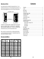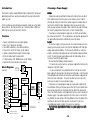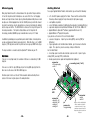
1
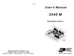
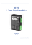
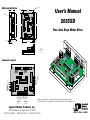
Mechanical Outline
1.50"
4x Ø.125
0.125"
User’s Manual
2.50"
2x Ø.125
3.70"
3.75"
2035XD
4.00"
Two Axis Step Motor Drive
0.25"
0.25"
0.15"
3.00"
.875"
6/4/03
JK
VDC+
VDCA+
AB+
B-
axis 1
axis 2
motor 2
A+
AB+
BOUT+
OUT-
STEP+
STEPDIR+
DIR+5VOUT
AN1
AN2
GND
STEP+
STEPDIR+
DIR-
motor 1
Connector Layout
Sold By: Servo Systems Co. • 53 Green Pond Road, Suite #2 • Rockaway, NJ 07866
(973) 335-1007 • Toll Free: (800) 922-1103 • Fax: (973) 335-1661 • www.servosystems.com
Applied Motion Products, Inc.
404 Westridge Drive Watsonville, CA 95076
Tel (831) 761-6555
(800) 525-1609
Fax (831) 761-6544
motors • drives • controls
Technical Specifications
Amplifiers
Dual, bipolar H-bridge, pulse width modulated three state switching at 20.5kHz. 12-35 VDC input. 0.1 - 2.0 amps/phase output
current, software selectable. 70 watts maximum output power per
axis. Automatic idle current reduction (software selectable),
reduces current when motor is not moving.
Digital Inputs Step/run 1, step/run 2, direction 1, direction 2. Differential,
optically isolated, 5V logic. 440 ohms internal resistance. Motor
steps on rising edge of STEP- input (and/or falling edge of
STEP+). 0.5 µsec minimum pulse width. 2 µsec minimum set up
time for direction signal.
Analog Inputs 0 to 5 VDC, 1K - 10K recommended impedance. 10 bit ADC.
Digital Output Optically isolated (photodarlington) 30VDC, 100 mA maximum
Physical
Mounted on 1/4 inch thick black anodized aluminum heat transfer
chassis. 1.5 x 3.0 x 4.0 inches overall. Power on green LED.
See drawing on page 16 for more information. Ambient temperature range: 0 to 70° C.
Connectors
European style screw terminal blocks. Wire size: AWG 16-28.
Motor 1 and DC input: 6 position (VDC+, VDC-, A+, A-, B+, B-)
Signal Input: 12 position (ST1+, ST1-, DR1+, DR1-,+5V, AN1,
AN2, GND, ST2+, ST2-, DR2+, DR2-)
Motor 2 and Output: 6 position (A+, A-, B+, B-, OUT+, OUT-)
Microstepping 15 software selectable step resolutions. With 1.8° motor:
200, 400, 2000, 5000, 10000, 12800, 18000, 20000, 21600,
25000, 25400, 25600, 36000, 50000, 50800. Microstep waveform: pure sine.
12,800 steps/rev in run/stop mode.
Other resolutions available to qualified OEMs upon request.
-2-
-15-
Mounting the Drive
Contents
You can mount your drive on the wide or the narrow side of the chassis. If you
mount the drive on the wide side, use #4 screws through the four corner holes. For
narrow side mounting applications, you can use #4 screws in the two side holes.
smooth flat surface
#4 screws
wide side mount
narrow side mount
The amplifiers in the drive generate heat. To operate the drive for more than a few
minutes you must properly mount it on a heat sinking surface. Applied Motion
Products can provide a compatible heat sink. In most cases, securing the drive to
the metal enclosure of your system will make an effective heat sink.
Never use your drive in a space where there is no air flow or where other devices
cause the surrounding air to be more than 70 °C. Never put the drive where it can
get wet or where metal particles can get on it.
Introduction ............................................................................................................... 4
Features ..................................................................................................................... 4
Block Diagram ........................................................................................................... 4
Getting Started .......................................................................................................... 5
Connecting the Power Supply ................................................................................... 6
Connecting the Motors .............................................................................................. 6
Connecting Logic ...................................................................................................... 7
Step and Direction Signals ........................................................................................ 8
Run/Stop Signals ...................................................................................................... 9
Connecting to the Analog Inputs ............................................................................. 10
Programmable Output ............................................................................................. 11
Schematic Diagram of Output Circuit ................................................................ 11
Sinking Output ................................................................................................... 11
Sourcing Output ................................................................................................. 11
Microstepping ......................................................................................................... 12
Choosing a Power Supply ....................................................................................... 13
Mounting the Drive ................................................................................................. 14
Recommended Motors ............................................................................................ 14
Technical Specifications .......................................................................................... 15
Mechanical Outline ................................................................................................. 16
Connector Layout .................................................................................................... 16
Recommended Motors
Motor
Number
HT11-012
HT11-013
5014-842
HT17-068
HT17-071
HT17-075
HT23-394
HT23-397
HT23-400
Size
inches
1.1 x 1.1 x 1.32
1.1 x 1.1 x 1.87
1.38 x 1.38 x 1.57
1.65 x 1.65 x 1.30
1.65 x 1.65 x 1.54
1.65 x 1.65 x 1.85
2.22 x 2.22 x 1.54
2.22 x 2.22 x 2.13
2.22 x 2.22 x 2.99
Winding
Connection
4 lead
4 lead
4 lead
parallel
parallel
parallel
parallel
parallel
parallel
-14-
Max Torque
oz-in
7
15
22
31
51
62
54
125
187
Current
Amps
1.0
1.0
1.0
1.3
1.7
1.7
2.0
2.0
2.0
-3-
Introduction
Choosing a Power Supply
Thank you for selecting an Applied Motion Products motor control. We hope our
dedication to performance, quality and economy will make your motion control
project successful.
Voltage
Chopper drives work by switching the voltage to the motor terminals on and off
while monitoring current to achieve a precise level of phase current. To do this
efficiently and silently, you'll want to have a power supply with a voltage rating at
least five times that of the motor. Depending on how fast you want to run the
motor, you may need even more voltage. More is better, the only upper limit being
the maximum voltage rating of the drive itself: 35 volts (including ripple).
If you choose an unregulated power supply, make sure that the no load voltage
does not exceed 35 volts DC. If the no load voltage is not specified, apply power to
the supply without connecting the 2035XD and measure the voltage.
Current
The maximum supply current you will need is the sum of the two phase currents.
However, you will generally need a lot less than that, depending on the motor type,
voltage, speed and load conditions. That's because the 2035XD uses switching
amplifiers, converting a high voltage and low current into lower voltage and higher
current. The more the power supply voltage exceeds the motor voltage, the less
current you'll need from the power supply.
We recommend the following selection procedure:
1. If you plan to use only a few drives, get a power supply with at least twice the
rated phase current of the motor.
2. If you are designing for mass production and must minimize cost, get one
power supply with more than twice the rated current of the motor. Install the motor
in the application and monitor the current coming out of the power supply and into
the drive at various motor loads. This will tell you how much current you really
need so you can design in a lower cost power supply.
If you plan to use a regulated power supply you may encounter a problem with
current foldback. When you first power up your drive, the full current of both motor
phases will be drawn for a few milliseconds while the stator field is being established. After that the amplifiers start chopping and much less current is drawn from
the power supply. If your power supply thinks this initial surge is a short circuit it
may "foldback" to a lower voltage. With many foldback schemes the voltage returns
to normal only after the first motor step and is fine thereafter. In that sense,
unregulated power supplies are better. They are also less expensive.
The PS430 from Applied Motion Products is a good supply to use with
the 2035XD.
If there's anything we can do to improve our products or help you use them better,
please call or fax. We'd like to hear from you. Our phone number is (800) 5251609 or you can reach us by fax at (831) 761-6544.
Features
•
•
•
•
•
•
•
•
Two axis step motor driver in one compact package
Drives sizes 11 through 23 step motors
Pulse width modulation, 3 state switching amplifiers
Phase current from 0.1 to 2.0 amps (set by software)
Optically isolated, differential step/run, direction inputs
0 to 5 volt analog inputs for speed control
15 step resolutions, 200 - 50800 steps/rev (set by software)
Automatic idle current reduction (set by software)
Block Diagram
(each axis)
connect to
power supply
(12-35 VDC)
step+
dir-
V-
eeprom
stepdir+
V+
A+
Optical
Isolation
x
OUT+
PWM
Amplifier
B+
B-
Controller
OUT-
A-
+5V
connections
to
motor
analog in
GND
RS-232
connections to indexer,
controller or other devices
-4-
connection to PC
for programming
-13-
Microstepping
Getting Started
To use your Applied Motion Products motor control, you will need the following:
Many step motor drives offer a choice between full step and half step resolutions.
In most full step drives, both motor phases are used all the time. Half stepping
divides each step into two smaller steps by alternating between both phases on and
one phase on. Microstepping drives like the 2035XD precisely control the amount
of current in each phase at each step position as a means of electronically subdividing the steps even further. The 2035XD offers a choice of full step, half step and 13
microstep resolutions. The highest setting divides each full step into 254
microsteps, providing 50,800 steps per revolution when using a 1.8° motor.
In addition to providing precise positioning and smooth motion, microstep drives
can be used to provide motion in convenient units. When the drive is set to 2000
steps/rev (1/10 step) and used with a 5 pitch lead screw, you get .0001 inches/step.
The step resolution is selected using the eXpositon™ software on your PC.
Restrictions
Restrictions:
If an axis is in run/stop mode, the resolution of that axis is automatically 12,800
steps/rev.
If one axis is set for full step (200 steps/rev) or half step (400 steps/rev) then the
other axis must be also set for 200 or 400 steps/rev.
• a 12-35 volt DC power supply for the motor. Please read the section entitled
Choosing a Power Supply for help in choosing the right power supply.
• a compatible step motor.
• a small flat blade screwdriver for tightening the connectors (included with drive).
• a personal computer running Microsoft Windows 95, 98, NT, Me, 2000 or XP.
• Applied Motion's eXposition™ software (supplied with drive on CD)
• Applied Motion Si™ programming cable.
If you plan to use the drive in Pulse & Direction Mode:
• a source of step pulses. Signal may be sinking (NPN), sourcing (PNP) or
differential.
• if your application calls for bidirectional rotation, you'll also need a direction
signal. This signal may also be sourcing, sinking or differential.
For Oscillator Mode:
• A run/stop signal or switch and a direction signal or switch. Signals may be
sinking (NPN), sourcing (PNP) or differential.
• Analog speed signal or speed control potentiometer (optional)
connector
• DC power supply
• motor 1
mounting hole (1 of 6)
Direction signal must be set at least 10 microseconds before activating the run
signal, or the move may take place in the wrong direction.
power
LED
connector
• step/run1, dir1
• step/run2, dir2
• analog in1
• analog in2
-12-
connector
• output
• motor 2
pc
connector
for programming
-5-
Always use the blue & white Applied
Motion screwdriver to tighten the
screw terminal connectors. Larger
screwdrivers may remove the plastic
dimples that prevent the screws from
falling out.
Connecting the Power Supply
Programmable Output
If you need information about choosing a power supply, please read Choosing a
Power Supply located on page 13 of this manual. The PS430 from Applied Motion
Products is a good supply for this drive.
The programmable output can be used to drive an LED, relay or the input of another
electronic device like a PLC or counter. The “+” (collector) and “-” (emitter) terminals of the phototransistor are available at the connector. This allows you to
configure the output for current sourcing or sinking. Diagrams of each type of
connection are shown below.
If your power supply does not have a fuse on the output or some kind of short
circuit current limiting feature you need to put a 4 amp fast acting fuse between the
drive and power supply. Install the fuse on the + power supply lead.
Connect the motor power supply "+" terminal to the driver terminal labeled "+
VDC". Connect power supply "-" to the drive terminal labeled "VDC-". Use no
smaller than 20 gauge wire. Be careful not to reverse the wires. Reverse connection
will destroy your driver, void your warranty and generally wreck your day.
inside 2035XD
+5V
330
OUT1+
OUT1–
processor
Optoisolator
NEC PS2501
or equiv.
+ VDC –
motor
+
supply
12-35 VDC –
fuse
Do not connect the output to more than 30VDC.
The current through the output terminals must not exceed 20 mA.
Schematic Diagram of Output Circuit
Connecting the Motors
Warning: When connecting a motor to the driver, be sure that the motor
power supply is off. Secure any unused motor leads so that they can't
short out to anything. Never disconnect the motor while the drive is
powered up. Never connect motor leads to ground or to a power supply!
You must now decide how to connect your
motor to the drive.
Four lead motors can only be connected one
way. Please follow the sketch at the right.
+
–
Load
OUT+
2035XD
OUT-
A+
A–
Red
4
lead
motor
Sinking Output
Blue
Six lead motors can be connected in series or
White
Yellow
center tap. In series mode, motors produce
B+
B–
more torque at low speeds, but cannot run as
4 Leads
fast as in the center tap configuration. In
series operation, the motor should be operated at 30% less than rated current to
prevent overheating. Wiring diagrams for both connection methods are shown on
the next page. NC means not connected to anything.
-6-
5-24 VDC
Power Supply
5-24 VDC
Power Supply
+
–
OUT+
COMMON
OUT-
INPUT
2035XD
Sourcing Output
-11-
PLC
Connecting to the Analog Inputs
The analog input of each axis can be used to control the motor speed when that axis
is programmed for oscillator mode. The speed may also be fixed and the analog
input ignored and left unconnected.
+5 volt DC is provided for powering potentiometers. A 1000 to 10000 ohm potentiometer is recommended and should be connected as shown below.
The +5V terminal is an output. Do not connect it to a power supply.
STEP+
run/stop switch
(closed=run)
DIR+
STEP-
direction switch
DIR-
+5
cw
ccw
A+
Green
A+
NC
Red/
Wht
Red
Black
B–
NC
A+
+5 VDC±5%
AIN
to ADC
GND
0 VDC
A 0 to 5 volt analog signal may also be used. Usually this signal comes from a
PLC, a PC with data aquisition card or a motion controller. Connections are shown
below.
B–
B+
signal return
DIRAIN
2035XD
direction switch
0 - 5V speed signal
STEP+
DIR+
STEP-
Red/
Wht
Black
B+
NC
6 Leads Center Tap Connected
A+
Blk/Wht
Org/
Wht
A–
Black
Red
B+
Red/
Wht
GND
Connecting an Analog Input to an Active Signal
-10-
Orange
Blk/Wht
8
lead
motor
Yellow
Yel/
Wht B–
8
lead
motor
Black
Red
Yel/
B+ Wht
8 Leads Series Connected
Yel
low
Red/Wht
B–
8 Leads Parallel Connected
Connecting Logic
run/stop switch
(closed=run)
Green
Red
Orange
Org/Wht
A–
Connecting an Analog Input to a Potentiometer
+
5 VDC
POWER
SUPPLY
-
6
lead
motor
White
Eight lead motors can also be connected in two ways: series or parallel. As with
six lead motors, series operation gives you more torque at low speeds and less
torque at high speeds. In series operation, the motor should be operated at 30%
less than the rated current to prevent over heating. The wiring diagrams for eight
lead motors are shown below.
100Ω
1-10kΩ
pot
6
lead
motor
White
NC
Grn/Wht
A–
6 Leads Series Connected
2035XD
+
5 VDC
POWER
SUPPLY
-
Grn/Wht
A–
220Ω
inside 2035XD
The 2035XD contains optical isolation circuitry to STEP+
prevent the electrical noise inherent in switching
amplifiers from interfering with your circuits.
220Ω
Optical isolation is accomplished by powering the STEPmotor driver from a different supply than your
Drive Input Circuit
circuits. There is no electrical connection between
the two: signal communication is achieved by infrared light. When your circuit
turns on or turns off an infrared LED (built into the drive) it signals a logic state to
the phototransistors that are wired to the brains of the drive. A schematic diagram of
the input circuit is shown at the right.
-7-
Step and Direction Signals
Indexer
with
Sinking
Outputs
Run/Stop Signals
+5V OUT
DIR+
DIR
DIRSTEP+
STEP
Most PLCs, don't use 5 volt logic. You can connect signal levels as high as 24
volts to the 2035XD if you add external dropping resistors to the STEP and DIR
inputs, as shown below.
2035XD
Drive
STEP-
Connecting to Indexer with Sinking Outputs
(includes Applied Motion Si-1 Indexer)
Indexer
with
Sourcing
Outputs
COM
DIR-
DIR
DIR+
STEP-
STEP
PLC
with
Sinking
Outputs
+12-24V
DIR+
DIR
DIRR
R
STEP
2035XD
Drive
STEP+
2035XD
Drive
STEP-
Connecting to PLC with Sinking (NPN) Outputs
(Most PLC's use 24 volt logic)
STEP+
Connecting to indexer with Sourcing Outputs
Indexer
with
Differential
Outputs
• For 12 volt logic, add 820 ohm, 1/4 watt resistors
• For 24 volt logic, use 2200 ohm, 1/4 watt resistors
DIR+
DIR+
DIR-
DIR-
STEP+
STEP+
STEP-
STEP-
PLC
with
Sourcing
Outputs
OUT1
DIR+
R
R
STEP-
OUT2
STEP+
GND
DIR-
2035XD
Drive
2035XD
Drive
Connecting to PLC with Sourcing (PNP) Outputs
(Most PLC's use 24 volt logic)
Connecting to Indexer with Differential Outputs
(Many High Speed Indexers have Differential Outputs)
+
+24VDC
Power
Supply
DIR+
direction switch
DIR2200
run/stop switch
(closed=run)
-
-8-
+12-24V
2200
STEP+
2035XD
Drive
STEP-
Using Mechanical Switches to Control Run/Stop and Direction
-9-