1
Gate Power
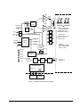
The FGPI board provides gate power for two or four SCRs and two or four status
feedbacks. The self-triggering circuit senses the bus voltage using two onboard
attenuator strings. Gate command and status feedback comes from the GGXD board
through a duplex fiber-optic link (POF). (See Figure 2.)
The gate current is a rectified ac waveform. Gate power from the FHVA is defined in
two stages, pedestal and backporch.
•
An initial application of power referred to as the pedestal (as seen by the gate
terminals on the FHVA board).
•
A second application of power is referred to as the backporch. It begins after
termination of the pedestal and continues for two seconds.
Cell Status
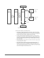
The FHVA board contains a circuit that detects the presence of voltage across the
SCR it is connected to. A signal signifying the presence of this voltage is generated
and sent through simplex POF to the FGPI board (Light = cell voltage detected). The
FGPI board receives the cell status signals from two or four SCRs. The status signals
are multiplexed and transmitted through a single simplex POF to the GGXD board
(see Figure 1).
Status Feedback
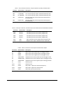
The following status feedbacks are serially transmitted through POF to the GGXD
board:
•
Board ID
•
Power Supply OK (2)
•
Cell Conduction Status (4)
•
Gate Status
•
Self-trigger
•
Thermal Limit
Trip Relay and Exciter Enable Outputs
The trip relay output provides 24 V dc to activate the trip relay, with both active high
and active low signals. This output is active whenever the FGPI board is commanded
to fire, in both the command and self-trigger modes. The FGPI board limits these
outputs to 40 mA. The power supply OK bit will be false if these outputs are shorted.
The exciter enable output is a set of contacts held normally closed by the
programmable logic device (PLD). The contacts open whenever the FGPI board is
triggered by the fiber-optic input, whenever it self-triggers, if the PLD malfunctions,
or if input power is lost. This output connects to the EXIC board's auxiliary logic
input (SG1, SG2). The open circuit voltage and short circuit current of the auxiliary
logic inputs are 120 V ac and 8 mA respectively.
4 • Crowbar Circuit Gate Power Interface Board IS200FGPI
GEI-100447