1
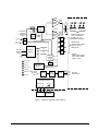
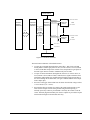
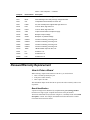
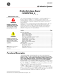
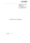
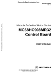
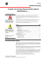
g GEI-100447 GE Industrial Systems Crowbar Circuit Gate Power Interface Board IS200FGPIG_A_ _ Safety Symbol Legend These instructions do not purport to cover all details or variations in equipment, nor to provide every possible contingency to be met during installation, operation, and maintenance. If further information is desired, or if particular problems arise that are not covered sufficiently for the purchaser’s purpose, the matter should be referred to GE Industrial Systems. Indicates a procedure or condition that, if not strictly observed, could result in personal injury or death. This document contains proprietary information of General Electric Company, USA, and is furnished to its customer solely to assist that customer in the installation, testing, operation, and/or maintenance of the equipment described. This document shall not be reproduced in whole or in part, nor shall its contents be disclosed to any third party without the written approval of GE Industrial Systems. Section Indicates a procedure or condition that, if not strictly observed, could result in damage to or destruction of equipment. Note Indicates an essential or important procedure or statement. Page Functional Description............................................................................................ 1 Gate Power ...................................................................................................... 4 Cell Status........................................................................................................ 4 Status Feedback ............................................................................................... 4 Trip Relay and Exciter Enable Outputs ........................................................... 4 Normal Firing .................................................................................................. 5 Bus Voltage Sensing and Self-trigger Function............................................... 5 Thermal Protection .......................................................................................... 5 Application Data ..................................................................................................... 6 Renewal/Warranty Replacement........................................................................... 10 How to Order a Board.................................................................................... 10 Handling Precautions..................................................................................... 12 Replacement Procedures................................................................................ 12 Functional Description The IS200FGPI Crowbar Circuit Gate Power Interface Board (FGPI) is a special purpose board used in the 3300 V and 6600 V Innovation Seriesä Medium Voltage SP Drives that serves as the interface between the Innovation Series control and the dc bus crowbar power circuit. The FGPI board accepts a power input of 84 volts to 130 volts (120 volts nominal), 50/60 Hz from a standard control power transformer (CPT). The board generates the various voltages needed for its own operation from this input. The board includes testpoints, test rings, and diagnostic LED indicators. It is located close to the power bridge and mounted on insulating standoffs. It is not conformal coated. The FGPI board interfaces with the IS200GGXD Expander Diode Source Board (GGXD), DS200FHVA High Voltage Gate Interface Board (FHVA), and IS200EXIC IGCT Exciter Control Interface Board (EXIC). See Figure 1 for board block diagram and Figure 2 for interfaces. Innovation Series is a trademark of General Electric Company, USA VPED PEDESTAL AMP FILTER DUPLEX FO LINK TO IS200GGXD DB1 R -21 dBm X U101 min -11 dBm min 650 nm TX FIRE CNTL (PLD) OVER TEMP IPED 36A pk VBKP BACK- IBKP 5Arms PORCH AMP U306 R R X FROM COMP STATUS SIGNALS U318 E101 E102 E103 A SINGLE WIRE THRU THE CT WINDOWS CONNECT ALL CT PRIMARIES IN SERIES U305 R R X SCR STATUS SIGNALS ONE FROM EACH FHVA VIA SIMPLEX FO U304 Vpedestal 120 Volts 50/60 Hz 225 VA 90V POWER SUPPLY P1 E401 E7 R U303 Vbackporch 40V R Vcontrol GND 5V, +/-15V R X R X NOTES: 3300V DRIVE USES 2 SCRS; 6600V DRIVE USES 4 SCRS MULTIPLEXER (PLD) CMD FO (R) 1 MHz GATE (R) PWR SUP UV DETECT TRIP (R) SELF TRG (Y) THLIM (R) TBKR OK (G) P5OK (G) PWR SUP OK E1,E4 SELF TRG TO FIRE CNTL FILT 1.6 KHz COMP ATTN E2,E5 E3,E6 VP VM VN 3500 OR 7000 Vdc PK RELAY CTL (PLD & DISCRETE CKTS) BREAKER TRIP NH TB1 C TB2 EXC TRIP NL TB3 SS RELAY TB4 TB5 SG1 SG2 AUX LOGIC INP EXTERNAL TO FGPI IS200EXIC Figure 1. FGPI Board Operation Block Diagram 2 • Crowbar Circuit Gate Power Interface Board IS200FGPI GEI-100447 120 Volts, 50/60 Hz IS200BICI BRIDGE INTERFACE IS200GGXD EXPANDER DIODE SRC IS200FGPI GATE PWR INTERFACE CELL STATUS SIMPLEX FO LINK GATE POWER EQUALIZER CURRENT DS200FHVA (1/SCR) GATE COMMAND AND MULTIPLEXED CELL STATUS FOR 2-4 SCRs JSRC SCR GATE POWER 2-4 FHVAs 5 Mbd Duplex FO Link SCSI, 50-PIN CELL STATUS SIMPLEX FO LINK EQUALIZER CURRENT DS200FHVA (1/SCR) SCR GATE POWER RELAY INTFC ATTEN INPUTS EXCITER OFF EXIC Figure 2. FGPI Board Interfaces The main features/functions of the FGPI board are: GEI-100447 • Accepts gate commands (through plastic optical fiber - POF) from a GGXD board, produces suitable gate power for two (in 3300 V drives) or four (in 6600 V drives) SCRs that comprise the crowbar circuit, and produces a gate pulse for the FHVA gate interface boards to simultaneously fire all SCRs. • Accepts cell status information (through POF) from two (in 3300 V drives) or four (in 6600 V drives) FHVA boards, combines these signals with other status information, and transmits the combined status through a single optical fiber to the control through the GGXD board. (The gate command and the status output form a duplex pair.) • Provides a self-trigger function that fires the SCRs when the bus voltage reaches 1.3 Per Unit (PU) (+0/−.05 PU). • Provides three discrete outputs for control of the main breaker and the exciter. These discrete outputs activate during normal firing and backup firing. A normally open relay contact is provided that is closed by the control to run the exciter. Normally high and normally low discrete outputs are provided to trip the main breaker through an external solid state relay. Crowbar Circuit Gate Power Interface Board IS200FGPI • 3 Gate Power The FGPI board provides gate power for two or four SCRs and two or four status feedbacks. The self-triggering circuit senses the bus voltage using two onboard attenuator strings. Gate command and status feedback comes from the GGXD board through a duplex fiber-optic link (POF). (See Figure 2.) The gate current is a rectified ac waveform. Gate power from the FHVA is defined in two stages, pedestal and backporch. • An initial application of power referred to as the pedestal (as seen by the gate terminals on the FHVA board). • A second application of power is referred to as the backporch. It begins after termination of the pedestal and continues for two seconds. Cell Status The FHVA board contains a circuit that detects the presence of voltage across the SCR it is connected to. A signal signifying the presence of this voltage is generated and sent through simplex POF to the FGPI board (Light = cell voltage detected). The FGPI board receives the cell status signals from two or four SCRs. The status signals are multiplexed and transmitted through a single simplex POF to the GGXD board (see Figure 1). Status Feedback The following status feedbacks are serially transmitted through POF to the GGXD board: • Board ID • Power Supply OK (2) • Cell Conduction Status (4) • Gate Status • Self-trigger • Thermal Limit Trip Relay and Exciter Enable Outputs The trip relay output provides 24 V dc to activate the trip relay, with both active high and active low signals. This output is active whenever the FGPI board is commanded to fire, in both the command and self-trigger modes. The FGPI board limits these outputs to 40 mA. The power supply OK bit will be false if these outputs are shorted. The exciter enable output is a set of contacts held normally closed by the programmable logic device (PLD). The contacts open whenever the FGPI board is triggered by the fiber-optic input, whenever it self-triggers, if the PLD malfunctions, or if input power is lost. This output connects to the EXIC board's auxiliary logic input (SG1, SG2). The open circuit voltage and short circuit current of the auxiliary logic inputs are 120 V ac and 8 mA respectively. 4 • Crowbar Circuit Gate Power Interface Board IS200FGPI GEI-100447 Normal Firing During a thermal limit condition, the gate power, the 1GATE status bit, and the gating LED are inactive. Light transmitted by the control initiates gate firing. The light power required to activate the fiber optic receiver is –21 dBm. The command is filtered using a time constant and a single-shot firing for two seconds initiates during which the following occurs: • Gate Power ON • 1GATE Status Bit High • Gating LED ON • Breaker Trip Active • Exciter Contacts Open Retriggering of the FGPI board is locked out for the duration of the single-shot event. Bus Voltage Sensing and Self-trigger Function The FGPI board senses the bus voltage directly using two attenuator strings. Attenuator taps are provided for both the 3300 V and 6600 V drives. The positive, negative and midpoint bus voltages are sensed. Note A method for using the FGPI board in a 4160V Innovation Series Medium Voltage - GP Type G drive is provided by a different group number of the board. During a thermal limit condition, the gate power, the 1GATE status bit, and the gating LED are inactive. The FGPI board provides a self-trigger method that fires the crowbar SCRs when the bus voltage reaches 1.3 PU (+0/-.05 PU). The command to self-trigger is filtered using a time constant and a single-shot firing for two seconds initiates during which the following occurs: • Gate Power ON • 1GATE Status Bit High • Gating LED ON • Self-trigger Status Bit High • Self-trigger LED ON • Breaker Trip Active • Exciter Contact Open The following items will remain latched until control power is cycled: • Self-trigger Status Bit High • Self-trigger LED ON Thermal Protection The FGPI board goes into thermal limit after approximately 6 minutes of continuous operation. The gate current ceases when the thermal limit is reached (an onboard temperature sensor is used) and the gating LED and status bit are inactive. The thermal limit status bit will be high and the thermal limit LED will be ON. The exciter contact, breaker trip output, self-trigger status bit, and self-trigger LED will behave normally. When the temperature has dropped through a defined band, the FGPI board will behave normally again. GEI-100447 Crowbar Circuit Gate Power Interface Board IS200FGPI • 5 Application Data The JTAG plug connector on the FGPI board is for development use only and not described in this document. The FGPI board includes five screw terminal connectors, eleven stab-on connectors, two plug connectors, six fiber-optic connectors, thirty-four user testpoints, three test rings, and eleven LED indicators. One potentiometer is provided to adjust the P5 voltage. This potentiometer is set at the factory and should not require further adjustment. Refer to Figure 3 for component locations and the following tables for descriptions. Table Description 1 P1 Plug Connector 2 Screw Terminal Connectors 3 Fiber-optic Connectors (for POF) 4 Stab-on Connectors 5 LED Indicators 6 Testpoints and Test Rings Table 1. P1 Plug Connector, Power Input from CPT Pin No. Description 1 120 V, 50/60 Hz ac (nominal) AC1 power input 2 120 V, 50/60 Hz ac (nominal) AC1 power input 3 120 V, 50/60 Hz ac (nominal) AC2 power input 4 120 V, 50/60 Hz ac (nominal) AC2 power input 6 • Crowbar Circuit Gate Power Interface Board IS200FGPI GEI-100447 CSTAT1 CSTAT3 ACOM GATE1 CMD E101 CSTAT2 GATE2 CSTAT4 INV2 E102 P90 INV1 STAT CHAS VLINK VSW E103 P40 IBKP N50 BIAS2 COND4 P15 COND3 PSOK COND1 N15 COND2 BIAS TRIP COND4 OCMD COND3 COND2 COND1 TPULL TPUSH TRP BKR R PUSH P5OK P5 BP PATT CHAS E401 BARCODE C ACOM NL V7.5 NATT TEMP MATT 3300N/4160N 3300M/4160M E4 E6 E5 6600M 6600P CHAS E7 3300P/4160P E1 OTL OST 1MHZ ACOM IS200FGPIG_A_ _ NH JTAG OSTAT PULL P1 THLIM S GATE CMD FO SELFTRIG TBRK EXC OFF E2 6600N E3 Figure 3. FGPI Board Layout Diagram GEI-100447 Crowbar Circuit Gate Power Interface Board IS200FGPI • 7 Table 2. Screw Terminal Connectors, Outputs to Breaker Trip Relay and EXIC Board Terminal Nomenclature Description TB1 NH (TRP BKR) 24 V dc active trip relay output to solid state breaker trip relay TB2 C (TRP BKR) 24 V dc active trip relay output to solid state breaker trip relay TB3 NL (TRP BKR) 24 V dc active trip relay output to solid state breaker trip relay TB4 S (EXC OFF) Normally closed relay contact output to EXIC board (open to turn exciter OFF) TB5 R (EXC OFF) Normally closed relay contact output to EXIC board (open to turn exciter OFF) Table 3. Fiber-optic Connectors, Cell Status Inputs from FHVA Boards and GGXD Board Interface Connector Nomenclature Description U303 CSTAT4 Cell status input from FHVA board 4 (simplex POF) U304 CSTAT3 Cell status input from FHVA board 3 (simplex POF) U305 CSTAT2 Cell status input from FHVA board 2 (simplex POF) U306 CSTAT1 Cell status input from FHVA board 1 (simplex POF) U101 CMD Gate command input from GGXD board (1/2 duplex POF) U318 STAT Multiplex status output to GGXD board (1/2 duplex POF) Table 4. Stab-on Connectors, Dc Bus Inputs and Gate Power Outputs Connector Nomenclature Description E1 6600P 6600 V drive dc bus positive input for self-trigger function E2 6600M 6600 V drive dc bus mid-point input for self-trigger function E3 6600N 6600 V drive dc bus negative input for self-trigger function E4 3300P/4160P 3300/4160 V drive dc bus positive input for self-trigger function E5 3300M/4160M 3300/4160 V drive dc bus mid-point input for self-trigger function E6 3300N/4160N 3300/4160 V drive dc bus negative input for self-trigger function E7 CHAS Chassis ground E401 CHAS Chassis ground E101 GATE1 Gate power 1 output to four FHVA boards (return) E102 GATE2 Gate power 2 output to four FHVA boards E103 CHAS Gate power ground to panel chassis 8 • Crowbar Circuit Gate Power Interface Board IS200FGPI GEI-100447 Table 5. LED Indicator Descriptions LED Color Nomenclature Description DS1 Red GATE Gating current is being supplied to the SCRs DS2 Yellow SELFTRIG Board has self-triggered and gated the SCRs. This indicator is latched ON until power is cycled DS3 Green TBRK_OK Trip breaker output is not shorted DS4 Red THLIM Board hotspot exceeded 80 °C and is still greater than 69 °C DS5 Red TRIP Trip breaker output and exciter OFF relay are activated DS101 Red CMD FO Fiber-optic command received DS303 Red COND4 Cell Status Feedback - SCR 4 is blocking voltage DS304 Red COND3 Cell Status Feedback - SCR 3 is blocking voltage DS305 Red COND2 Cell Status Feedback - SCR 2 is blocking voltage DS306 Red COND1 Cell Status Feedback - SCR 1 is blocking voltage DS401 Green P5OK 5 V power supply is healthy Table 6. User Testpoints and Test Rings Testpoint Nomenclature Description TP1 TPUSH Q102 drain, drives transformer that supplies gate power TP2 TPULL Q103 drain, drives transformer that supplies gate power TP3 OCMD Turn-on command from fiber-optic receiver, low active TTL TP4 OSTAT Status signal to fiber-optic transmitter, low active TTL TP5 TEMP Voltage corresponding to board temperature (hot spot) TP6 PATT Attenuated signal from positive high voltage attenuator TP7 NATT Attenuated signal from negative high voltage attenuator TP8 OST Self-trigger activated, low active TTL TP9 BIAS Bias current for power supply oscillator startup TP10 BP Rectified ac input power, positive TP11 N50 Regulated voltage 50 V dc below BP for use in power supply TP12 BIAS2 Regulated voltage 12 V dc above N50 for power supply control TP13 INV1 Q403 drain, drives power supply transformer TP14 INV2 Q404 drain, drives power supply transformer TP15 ACOM Analog common (test ring) TP16 ACOM Analog common (test ring) TP17 ACOM Analog common (test ring) TP18 P15 Positive 15 V dc TP19 N15 Negative 15 V dc GEI-100447 Crowbar Circuit Gate Power Interface Board IS200FGPI • 9 Table 6. User Testpoints continued Testpoint Nomenclature Description TP20 V7.5 7.5 V dc reference for self-trigger comparator circuits TP21 MATT Attenuated signal from mid-point high voltage attenuator TP22 OTL Temperature limit exceeded, low active TTL TP23 PSOK P5, P40 and P90 power supplies OK, high active TTL TP101 PULL Turns on Q103, high active TTL TP102 PUSH Turns on Q102, high Active TTL TP103 VSW Output of buck switch in backporch supply TP104 IBKP Backporch output voltage TP105 VLINK Backporch or pedestal voltage TP303 COND4 Cell #4 is conducting, active high TTL TP304 COND3 Cell #3 is conducting, active high TTL TP305 COND2 Cell #2 is conducting, active high TTL TP306 COND1 Cell #1 is conducting, active high TTL TP313 1MHZ 1MHZ oscillator output for PLD, TTL TP401 P5 Positive 5 V dc TP405 P90 Positive 90 V dc TP406 P40 Positive 40 V dc Renewal/Warranty Replacement How to Order a Board When ordering a replacement board for a GE drive, you need to know: • How to accurately identify the part • If the part is under warranty • How to place the order This information helps ensure that GE can process the order accurately and as soon as possible. Board Identification A printed wiring board is identified by an alphanumeric part (catalog) number located near its edge. Figure 4 explains the structure of the part number. The board’s functional acronym, shown in Figure 4, is normally based on the board description, or name. For example, the FGPI board is described as the Crowbar Circuit Gate Power Interface board. 10 • Crowbar Circuit Gate Power Interface Board IS200FGPI GEI-100447 IS 200 FGPI G# A A A Artwork revision1 Functional revision1 Functional revision2 Group (variation, G or H) Functional acronym Assembly level3 Manufacturer (DS & IS for GE in Salem, VA) 1 Backward compatible Not backward compatible 3200 indicates a base-level board; 215 indicates a higher-level assembly or added components (such as PROM) 2 Figure 4. Board Part Number Conventions Warranty Terms The GE Terms and Conditions brochure details product warranty information, including warranty period and parts and service coverage. The brochure is included with customer documentation. It may be obtained separately from the nearest GE Sales Office or authorized GE Sales Representative. Placing the Order (“+” indicates the international access code required when calling from outside of the USA.) Parts still under warranty may be obtained directly from the factory: GE Industrial Systems Product Service Engineering 1501 Roanoke Blvd. Salem, VA 24153-6492 USA Phone: + 1 800 533 5885 (United States, Canada, Mexico) + 1 540 378 3280 (International) Fax: + 1 540 387 8606 (All) Renewals (spares or those not under warranty) should be ordered by contacting the nearest GE Sales or Service Office. Be sure to include the following when ordering any warranty or renewal parts: • Complete part number and description • Drive serial number • Drive Material List (ML) number Note All digits are important when ordering or replacing any board. The factory may substitute later versions of replacement boards based on availability and design enhancements. However, GE Industrial Systems ensures backward compatibility of replacement boards. GEI-100447 Crowbar Circuit Gate Power Interface Board IS200FGPI • 11 Handling Precautions To prevent component damage caused by static electricity, treat all boards with static sensitive handling techniques. Wear a wrist grounding strap when handling boards or components, but only after boards or components have been removed from potentially energized equipment and are at a normally grounded workstation. Printed wiring boards may contain static-sensitive components. Therefore, GE ships all replacement boards in antistatic bags. Use the following guidelines when handling boards: • Store boards in antistatic bags or boxes. • Use a grounding strap when handling boards or board components (per previous Caution criteria). Replacement Procedures To prevent electric shock, turn off power to the drive, then test to verify that no power exists in the board before touching it or any connected circuits. To prevent equipment damage, do not remove, insert, or adjust board connections while power is applied to the equipment. Ø To replace the FGPI board 1. Make sure that the drive in which the board resides has been de-energized. (Refer to the appropriate User's Manual, GEH-6419, for complete de-energizing procedures and follow all local practices of lock-out/tag-out.) 2. Open the rear bridge control cabinet door, and using equipment designed for high voltages, test any electrical circuits before touching them to ensure that power is off. 3. Locate the FGPI board and carefully disconnect all cables from the board as follows: • Verify all cables are labeled with the correct connector name (as marked on the board) to simplify reconnection. • Grasp each side of a stab-on connector that joins with the board's stab terminal and gently pull the stab-on connector loose. • For cables with pull-tabs, carefully pull the tab. • For screw terminal connections, loosen the screw and remove the wire connector from the terminal. • For fiber-optic cables, depress the latch on the mating connector and remove the fiber-optic cable. 12 • Crowbar Circuit Gate Power Interface Board IS200FGPI GEI-100447 Avoid dropping any mounting hardware into the equipment as this could cause damage when power is reapplied. GEI-100447 4. Remove the nine screws that hold the FGPI board to the insulating standoffs, and remove the board. 5. Orient the new FGPI board in the same position as the one removed and install it into the standoffs with the nine screws removed in step 4. 6. Reconnect all cables to FGPI board as labeled and ensure that cables are properly seated at both ends. 7. Close the bridge control cabinet door. Crowbar Circuit Gate Power Interface Board IS200FGPI • 13 Notes g GE Industrial Systems General Electric Company 1501 Roanoke Blvd. VAIS200FGPI 24153-6492 USA 14 • Crowbar Circuit Gate Power InterfaceSalem, Board Issue date: 2000-02-16 2000 by General Electric Company, USA. All rights reserved. GEI-100447