1
FOREWORD
Thank you for purchasing HD5L series elevator controller manufactured by
Shenzhen Hpmont Technology Co., Ltd..
This User Manual describes how to use HD5L series elevator controller and
their installation wiring, parameter setting, troubleshooting and daily maintenance
etc. Before using the product, please read through this User Manual carefully. In
addition, please do not use this product until you have fully understood safety
precautions.
Note:
Preserve this Manual for future.
Due to product upgrade or specification change, and for the purpose of improving
convenience and accuracy of this manual, this manual’s contents may be modified.
If you need the User Manual due to damage, loss or other reasons, please contact
the regional distributor of our company or directly contact our company Technical
Service Center.
For the first time using, the user should carefully read this manual.
If you still have some problems during use, please contact our company Technical
Service Center.
Telephone: 4008-858-959 or 189 4871 3800
The product warranty is on the last page of this Manual, please preserve it for future.
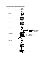
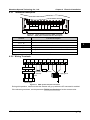
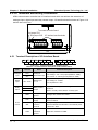
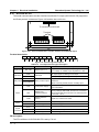
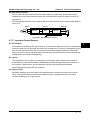
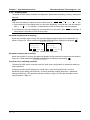
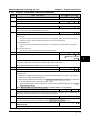
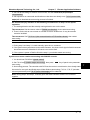
Connection with peripheral devices
Three-phase AC power supply
MCCB
Contactor
AC input reactor
EMI filter
Braking resistor
(optional)
Controller
DC reactor
(optional)
Ground connection
EMI filter
AC output reactor
Motor
Ground connection
CONTENTS
Chapter 1 Safety Information and Precautions ............................................................................ 1
1.1 Safety Definition ............................................................................................................... 1
1.2 About Motor and Load ...................................................................................................... 1
1.3 Installation Limitation ........................................................................................................ 2
Chapter 2 Product Information...................................................................................................... 3
2.1 Model Explanation............................................................................................................ 3
2.2 Nameplate ....................................................................................................................... 3
2.3 Specifications ................................................................................................................... 4
2.4 Ratings............................................................................................................................. 6
2.5 Parts of Controller ............................................................................................................ 7
Chapter 3 Mechanical Installation ................................................................................................. 9
3.1 Installation Precautions .................................................................................................... 9
3.2 Requirement for the Installation Site ................................................................................. 9
3.3 Installation Direction and Space Requirements ............................................................... 10
3.4 Dimensions and Mounting Size ...................................................................................... 10
3.5 Panel Installation and Dismantle..................................................................................... 12
3.6 Plastic Cover Dismantle ................................................................................................. 13
Chapter 4 Electrical Installation .................................................................................................. 15
4.1 Wiring Precautions ......................................................................................................... 15
4.2 Selection of Main Circuit Peripheral Devices ................................................................... 16
4.3 Main Circuit Terminals and Wiring ................................................................................... 16
4.3.1 Terminals Description......................................................................................... 17
4.3.2 Wiring Terminals ................................................................................................ 17
4.4 Control Terminals and Wire Connection .......................................................................... 18
4.4.1 Control Terminal Description .............................................................................. 19
4.4.2 Wire Jumper Description.................................................................................... 20
4.4.3 SCI Communication Terminal Description .......................................................... 20
4.4.4 Control Terminal Wiring...................................................................................... 21
4.5 I/O Terminals and Wiring Connection .............................................................................. 26
4.5.1 Terminal Description of I/O Interface Board ........................................................ 26
4.5.2 Wire Jumper Description of I/O Interface Board ................................................. 27
4.5.3 Terminal Connection of I/O Interface Board ........................................................ 27
4.6 Encoder Interface Board................................................................................................. 28
4.6.1 Encoder Interface Board Introduction ................................................................. 28
4.6.2 FD Description................................................................................................... 28
4.6.3 DB15 Terminal ................................................................................................... 29
4.6.4 HD-PG2-OC-FD ................................................................................................ 29
4.6.5 HD-PG5-SINCOS-FD ........................................................................................ 32
4.6.6 HD-PG6-UVW-FD.............................................................................................. 34
4.6.7 HD-PG9-SC-FD ................................................................................................. 36
4.7 Meet EMC Requirement of Installation............................................................................ 37
4.7.1 Correct EMC Installation .................................................................................... 37
4.7.2 Wiring Requirement ........................................................................................... 38
4.7.3 Wiring Motor ...................................................................................................... 38
4.7.4 Ground Connections .......................................................................................... 39
4.7.5 EMI Filter ........................................................................................................... 40
4.7.6 Conduction, Radiation and Radio Frequency Interference Countermeasures ..... 40
4.7.7 Input and Output Reactor................................................................................... 41
Chapter 5 Operation Instructions................................................................................................ 43
5.1 Function Description....................................................................................................... 43
5.1.1 Operation Mode ................................................................................................. 43
5.1.2 Control Mode ..................................................................................................... 44
5.1.3 Controller State.................................................................................................. 44
5.1.4 Controller Running Mode ................................................................................... 44
5.2 Operating Instructions .................................................................................................... 45
5.2.1 Panel Description .............................................................................................. 45
5.2.2 Display State ..................................................................................................... 46
5.2.3 Panel Operation Examples ................................................................................ 48
5.3 Initial Power On .............................................................................................................. 52
Chapter 6 Function Introduction ................................................................................................. 53
6.1 Group D: Display Parameters ......................................................................................... 54
6.1.1 Group D00 System State Parameters ................................................................ 54
6.1.2 Group D01 Drive State Parameters.................................................................... 55
6.1.3 Group D02 Analogue State Display Parameters ................................................. 56
6.1.4 Group D03 Running State Parameters ............................................................... 57
6.1.5 Group D04 Encoder State Parameters ............................................................... 58
6.2 Group F: General Function Parameters .......................................................................... 59
6.2.1 Group F00 Basic Parameters ............................................................................. 59
6.2.2 Group F01 Protection of Parameters .................................................................. 61
6.2.3 Group F02 Start & Stop Parameters .................................................................. 62
6.2.4 Group F03 Acceleration/Deceleration Parameters .............................................. 63
6.2.5 Group F04 Analogue Curve Parameters ............................................................ 64
6.2.6 Group F05 Speed Parameters ........................................................................... 65
6.2.7 Group F06 Weighing Compensation Parameters ............................................... 67
6.2.8 Group F07 Asynchronous Motor Parameters...................................................... 68
6.2.9 Group F08 Motor Vector Control Speed-loop Parameters................................... 71
6.2.10 Group F09 Current-loop Parameters ................................................................ 72
6.2.11 Group F10 Synchronous Motor Parameters ..................................................... 72
6.2.12 Group F11 PG Parameters............................................................................... 73
6.2.13 Group F12 Digital I/O Terminal Parameters ...................................................... 74
6.2.14 Group F13 Analogue I/O Terminal Parameters ................................................. 77
6.2.15 Group F14 SCI Communication Parameters .................................................... 79
6.2.16 Group F15 Display Control Parameters ............................................................ 80
6.2.17 Group F16 Enhance Function Parameters ....................................................... 81
6.2.18 Group F17 Fault Protect Parameters................................................................ 82
6.2.19 Group F18 PWM Parameters ........................................................................... 85
6.2.20 Group F19 Reserved ....................................................................................... 85
6.2.21 Group F20 Reserved ....................................................................................... 85
6.3 Group Y Manufacturer Function Parameters ................................................................... 85
Chapter 7 Elevator Application Guidance................................................................................... 87
7.1 Basic Debug Procedures ................................................................................................ 87
7.1.1 System Analysis and Wire.................................................................................. 87
7.1.2 Set Basic Parameters ........................................................................................ 87
7.1.3 Motor Parameter Auto-tuning ............................................................................. 88
7.1.4 Inspection Running ............................................................................................ 92
7.1.5 Run Fast............................................................................................................ 92
7.2 Terminal MS Run Mode Application ................................................................................ 93
7.2.1 Control Part Connection..................................................................................... 93
7.2.2 Set Parameter ................................................................................................... 94
7.3 Terminal Analogue Run Mode Application ....................................................................... 96
7.3.1 Control Part Connection..................................................................................... 96
7.3.2 Set Parameter ................................................................................................... 96
7.4 Power-off Battery Driven Run Mode Application .............................................................. 98
7.4.1 Basic Connection............................................................................................... 98
7.4.2 Running Time Sequence.................................................................................... 98
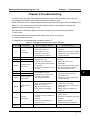
Chapter 8 Troubleshooting.......................................................................................................... 99
Chapter 9 Maintenance .............................................................................................................. 103
9.1 Daily Maintenance ........................................................................................................ 104
9.2 Periodical Maintenance ................................................................................................ 104
9.3 Replacing Damaged Parts ............................................................................................ 105
9.4 Unwanted Controller Recycling..................................................................................... 105
Chapter 10 Accessories............................................................................................................. 107
10.1 Panel Installation Assembly ........................................................................................ 107
10.1.1 Mounting Base............................................................................................... 107
10.1.2 Extension Cable ............................................................................................ 107
10.2 Braking Resistor Selection.......................................................................................... 108
10.3 Protective Cover......................................................................................................... 108
10.4 Power Regenerative Unit ............................................................................................ 108
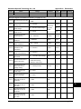
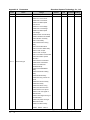
Appendix A Parameters ............................................................................................................. 109
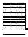
Appendix B Communication Protocol ...................................................................................... 129
Safety Information and Precautions
1
Product Information
2
Mechanical Installation
3
Electrical Installation
4
Operation Instructions
5
Function Introduction
6
Elevator Application Guidance
7
Troubleshooting
8
Maintenance
9
Accessories
10
Parameters
A
Communication Protocol
B
Shenzhen Hpmont Technology Co., Ltd.
Chapter 1
Safety Information and Precautions
Chapter 1 Safety Information and Precautions
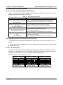
1.1 Safety Definition
Danger
Warning
Note
Danger: A Danger contains information which is critical for avoiding safety
hazard.
1
Warning: A Warning contains information which is essential for avoiding a
risk of damage to product or other equipments.
Note: A Note contains information which helps to ensure correct operation
of the product.
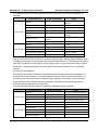
1.2 About Motor and Load
Compared to the standard frequency operation
The HD5L series controllers are voltage-type controllers and their output is PWM wave with
certain harmonic wave. Therefore, the temperature, noise and vibration of the motor will be a little
higher than that at standard frequency operation.
Motor’s overload protecting threshold
When choose the adaptive motor, the controller can effectively implement the motor thermal
protection. Otherwise it must adjust the motor protection parameters or other protection
measures to ensure that the motor is at a safe and reliable operation.
Lubrication of mechanical devices
At long time low-speed operation, it should provide periodical lubrication maintenance for the
mechanical devices such as gear box and geared motor etc. to make sure the drive results meet
the site need.
Check the insulation of the motor
For the first time using of the motor or after long time storage, it need check the insulation of the
motor to avoid damage the controller because of the worse insulation motor.
Note:
Please use a 500V Mega-Ohm-Meter to test and the insulation resistance must be higher than
5Mohm.
HD5L Series Controller
User Manual
―1―
Chapter 1
Safety Information and Precautions
Shenzhen Hpmont Technology Co., Ltd.
1.3 Installation Limitation
No capacitor or varistor on the output side
Since the controller output is PWM wave, it is strictly forbidden to connect capacitor for improving
the power factor or varistor for lightning protection to the output terminals so as to avoid the
controller fault tripping or component damage.
Contactors and circuit breakers connected to the output of the controller
If circuit breaker or contactor needs to be connected between the controller and the motor, be
sure to operate these circuit breakers or contactor when the controller has no output, so as to
avoid any damage to the controller.
Rated voltage
The controller is prohibited to be used beyond the specified range of operation voltage. If needed,
please use the suitable voltage regulation device to change the voltage.
Change three-phase input to single-phase input
For three-phase input controller, the users should not change it to be single-phase input.
If you have to use single-phase power supply, you should disable the input phase-loss protection
function. And the bus-voltage and current ripple will increase, which not only influences the life of
electrolytic capacitor but also deteriorates the performance of the controller. In that case, the
controller must be derating and should be within the controller 60% rated value.
Lightning surge protection
The controller internal design has lightning surge overcurrent protection circuit, and has certain
self-protection capacity against the lightning.
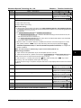
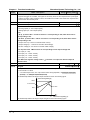
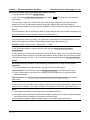
Altitude and derating
In the altitude exceeded 1000 meters area, since the heatsink efficiency will be reduced because
of the tenuous air, the controller should be derating. Figure 1-1 is the derating curve of the
controller rated current and the altitude.
Controller’s rated current
100%
80%
Figure 1-1
―2―
Altitude(m)
1000
4000
Derating curve of controller rated current and altitude
HD5L Series Controller
User Manual
Shenzhen Hpmont Technology Co., Ltd.
Chapter 2
Product Information
Chapter 2 Product Information
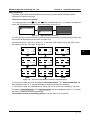
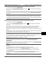
2.1 Model Explanation
HD5L - 4 T 5P5
Adaptive motor power
Refer to section 2.4 about rating
Input phases
S : single-phase
T : three-phase
2
Voltage ratings
2 : 200-240V
4 : 380-460V
Product series
Elevator controller
2.2 Nameplate
Product model
Adaptive motor
Input specification
Output specification
Software version
MODEL: HD5L-4T5P5
POWER: 5.5kW
INPUT: 3PH 380-460V 15A 50/60Hz
OUTPUT: 8.5kVA 0-460V 13A 0-100Hz
Version: 1.00
Serial number
S/N:
Barcode
Shenzhen Hpmont Technology Co., Ltd
HD5L Series Controller
User Manual
―3―
Chapter 2
Product Information
Shenzhen Hpmont Technology Co., Ltd.
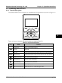
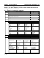
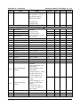
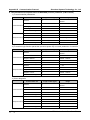
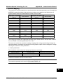
2.3 Specifications
Item
Rated voltage and
frequency
Electrical
Accuracy
Three-phase: 380-460V, 50/60Hz
Voltage: fluctuation within ± 10%, imbalance rate < 3%
Frequency: ± 5%
Output voltage
0-input voltage
Output frequency
0-100.00Hz
Maximum current
Control mode
Performance
Characteristic
Protection
―4―
Specification
Single-phase: 200-240V, 50/60Hz
150% rated output current for 2 minutes
180% rated output current for 10 seconds
V/f control; Open-loop vector control (SVC);
Closed-loop vector control (VC)
Operation command
control mode
Panel control; external terminal control; host computer communication
control via SCI communication port
Speed setting mode
Digital setting, analogue setting, SCI communication setting
Speed setting
resolution
Digital setting: 0.01Hz
Speed control accuracy
SVC: ± 0.5%
VC: ± 0.05%
Speed control range
SVC: 1:100
VC: 1:1000
Torque control
response
SVC: < 200ms
VC: < 50ms
Start torque
SVC: 180% rated-torque /0.5Hz
VC: 200% rated-torque /0Hz
Parameter upload and
download function
To achieve parameters uploading or downloading
Programmable I/O
interface
Analogue setting: 0.1% × max-frequency
The programmable input interface has up to 34 functions
The pragrammable output interface has up to 19 functions
Communication
protocol
Controller is built-in MODBUS communication protocol
Auto-inspection
To eliminate the potential safety problems, safety inspection for the
peripheral devices is provided when power is on
Over-speed protection
To make sure safe running, elevator over-speed protection is provided
Speed deviation
protection
To eliminate the potential safety problems, speed deviation detection
protection is provided
Up/down forced
deceleration function
Up/down forced deceleration function, to avoid climbing elevator or plunging
elevator
I/O phase loss
protection
I/O phase loss auto-detect and alarm function
Motor temperature
detection
Real time detection for the motor temperature
Power output
grounding fault
protection
Power output grounding fault protection is enabled
Power output short
circuit protection
Power output short circuit protection is enabled
HD5L Series Controller
User Manual
Shenzhen Hpmont Technology Co., Ltd.
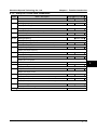
Item
Chapter 2
Product Information
Specification
+10V, maximum current 100mA
Analogue supply
-10V, maximum current 10mA
Digital supply
+24V, maximum current 200mA
AI1 (control board): voltage 0-10V
I/O feature
AI2, AI3 (control board): -10V-+10V/0-20mA (voltage/current is
selectable)
Analogue input
AI4 (I/O interface board): -10V-+10V/0-20mA (voltage/current is
selectable, and differential input is supported)
Analogue output
AO1, AO2: 0-10V/0-20mA (voltage/current is selectable)
Digital input
DI1-DI6 (control board); DI7-DI12 (I/O interface board)
Digital output
2
DO1, DO2
Programmable relay
output
R1A/R1B/R1C (control board)
R2A/R2B/R2C; R3A/R3B/R3C; R4A/R4B/R4C (I/O interface board)
Contact rating 250VAC/3A or 30VDC/1A
Communication
Panel
SCI communication
RS-485 interface
LCD display
Function parameter setting, check the state parameters and the fault code
etc.
Parameter copy
To achieve quick parameter copy
Operation temperature
The derating value of the output current of the controller shall be 2% for each
degree centigrade above 40℃. Max. allowed temperature is 50℃
-10-+40℃, air temperature fluctuation is less than 0.5℃/min
Environment
Storage temperature
-40-+70℃
Location for use
Indoor, preventing from direct sunlight, no dust, corrosive, flammable gases,
oil mist, water vaper, dripping or salt etc.
Altitude
Less than 1000 meters, otherwise should be derating use
Humidity
Less than 95%RH, non-condensing
Ocsillation
Less than 5.9m/s2 (0.6g)
OC encoder interface board with frequency demultiplication output
(HD-PG2-OC-FD)
SINCOS encoder interface board with frequency demultiplication output
(HD-PG5-SINCOS-FD)
Encoder interface
board
Line drive encoder interface board with frequency demultiplication output
(HD-PG6-UVW-FD)
Options
Serial communication encoder interface board with frequency
demultiplication output (HD-PG9-SC-FD) (support Endat)
Mounting base to panel (HD-KMB)
1 meter extension cable to panel (HD-CAB-1M)
About panel
2 meter extension cable to panel (HD-CAB-2M)
3 meter extension cable to panel (HD-CAB-3M)
6 meter extension cable to panel (HD-CAB-6M)
Enhanced protection
Protective cover (HD-CK-Frame4)
Power unit
Power regenerative unit (HDRU)
HD5L Series Controller
User Manual
―5―
Chapter 2
Product Information
Shenzhen Hpmont Technology Co., Ltd.
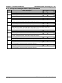
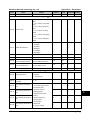
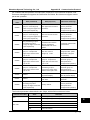
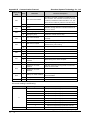
2.4 Ratings
Rated capacity
Rated input current Rated output current
Motor power
Model
(kVA)
(A)
(A)
(kW)
Single-phase power supply: 200-240V, 50/60Hz
HD5L-2S2P2
3.8
24.1
10
2.2
HD5L-2S3P7
5.9
40
17
3.7
Three-phase power supply: 200-240V, 50/60Hz
HD5L-2T3P7
5.9
19
17
3.7
HD5L-2T5P5
8.5
28
25
5.5
HD5L-2T7P5
11
35
32
7.5
HD5L-2T011
16
47
45
11
HD5L-2T015
21
62
55
15
HD5L-2T018
24
77
70
18.5
HD5L-2T022
30
92
80
22
HD5L-2T030
39
113
110
30
Three-phase power supply: 380-460V, 50/60Hz
―6―
HD5L-4T2P2
3.4
7.3
5.1
2.2
HD5L-4T3P7
5.9
11.9
9.0
3.7
HD5L-4T5P5
8.5
15
13
5.5
HD5L-4T7P5
11
19
17
7.5
HD5L-4T011
16
28
25
11
HD5L-4T015
21
35
32
15
HD5L-4T018
24
39
37
18.5
HD5L-4T022
30
47
45
22
HD5L-4T030
39
62
60
30
HD5L-4T037
49
77
75
37
HD5L-4T045
59
92
90
45
HD5L Series Controller
User Manual
Shenzhen Hpmont Technology Co., Ltd.
Chapter 2
Product Information
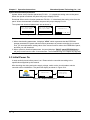
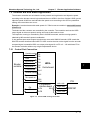
2.5 Parts of Controller
Mounting hole
Fan cover
Mounting hole
Middle enclosure
Upper cover
Bottom enclosure
Display panel
Certification
2
Nameplate
Lower cover
Control terminal connection hole
Plastic structure
HD5L Series Controller
Power terminal
connection hole
User Manual
Metal structure
―7―
Chapter 2
Product Information
Shenzhen Hpmont Technology Co., Ltd.
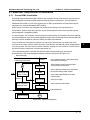
I/O interface
board
Refer to section 4.5
Control board
Refer to section 4.4
Encoder
interface
board
(optional)
Refer to section4.6
L1 L2 L3
POWER
―8―
P1 (+) (-) BR
U
V
W
MOTOR
PE
HD5L Series Controller
User Manual
Shenzhen Hpmont Technology Co., Ltd.
Chapter 3 Mechanical Installation
Chapter 3 Mechanical Installation
3.1 Installation Precautions
Danger
• Do not install if the controller is imcomplete or impaired.
• Make sure that the controller is far from the explosive and combustible things.
• Do not operate the controller until the power is cut-off 10 minutes later.
3
Warning
• It is required not only carry the panel and the cover but also the controller bottom enclosure.
• Do not play metal into the controller when installing.
123
3.2 Requirement for the Installation Site
Ensure the installation site meeting the following requirements:
Do not install at the direct sunlight, moisture, water droplet location;
Do not install at the combustible, explosive, corrosive gas and liquid location;
Do not install at the oily dust, fiber and metal powder location;
Be vertical installation on fire-retardant material with a strong support;
Make sure adequate cooling space for the controller so as to keep the ambient temperature
between - 10-+ 40℃;
• Install at where the vibration is less than 5.9m/s2 (0.6g).
•
•
•
•
•
Note:
1. It needs derating use if the controller operation temperature exceeds 40℃. The derating value
of the output current of the controller shall be 2% for each degree centigrade. Max. allowed
temperature is 50℃.
2. Keep ambient temperature between -10-+40℃. It can improve the controller operation
performance if install at the location with good ventilation or cooling devices.
HD5L Series Controller
User Manual
―9―
Chapter 3 Mechanical Installation
Shenzhen Hpmont Technology Co., Ltd.
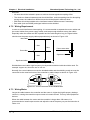
3.3 Installation Direction and Space Requirements
To achieve good cooling efficiency, install the controller perpendicularly and always provide the
following space to allow normal heat dissipation. The requirements on mounting space and
clearance are shown in Figure 3-1.
≥50
≥30
≥30
≥50
Figure 3-1
Installation of the controller
3.4 Dimensions and Mounting Size
4-Ød
D
H2
H
H1
W
W1
Dimensions figure 1
―10―
HD5L Series Controller
User Manual
Shenzhen Hpmont Technology Co., Ltd.
Chapter 3 Mechanical Installation
W
D
H2
4-Ød
H1
H
W1
3
Dimensions figure 2
Table 3-1 HD5L dimensions
Dimensions (mm)
Mounting size (mm)
GW
Model
Figure
W
H
D
W1
H1
H2
d
(kg)
200
299
210
146
286
280
5
5.8
1
235
353
222
167
337
330
7
8.2
1
290
469
240
235
445
430
8
20.4
2
380
598
290
260
576
550
10
48
2
HD5L-2S2P2
HD5L-2S3P7
HD5L-2T3P7
HD5L-2T5P5
HD5L-4T2P2
HD5L-4T3P7
HD5L-4T5P5
HD5L-4T7P5
HD5L-4T011
HD5L-2T7P5
HD5L-4T015
HD5L-4T018
HD5L-2T011
HD5L-2T015
HD5L-2T018
HD5L-4T022
HD5L-4T030
HD5L-2T022
HD5L-2T030
HD5L-4T037
HD5L-4T045
HD5L Series Controller
User Manual
―11―
Chapter 3 Mechanical Installation
Shenzhen Hpmont Technology Co., Ltd.
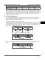
3.5 Panel Installation and Dismantle
According to the direction of the Figure 3-2, press the panel until hear a “click” sound. Do not
install the panel from other directions or it will cause poor contact.
PRG
SHF
RUN
JOG
ENT
STOP
Figure 3-2
Installation of the panel
There are two steps in Figure 3-3.
First, press the hook of the panel according to the direction 1.
Second, take out of the panel according to the direction 2.
1
2
PRG
SHF
RUN
JOG
ENT
STOP
Figure 3-3
―12―
Dismantle of the panel
HD5L Series Controller
User Manual
Shenzhen Hpmont Technology Co., Ltd.
Chapter 3 Mechanical Installation
3.6 Plastic Cover Dismantle
The upper cover and the lower cover of the HD5L series controller are removable. The dismantle
step is shown as Figure 3-4.
Before removing the upper cover, please take away the panel.
3
(a)
The removing proceeses
of plastic cover board:
1.Extrude the hooks at both side together,
take off the lower cover, as (a).
2.Dismantle the screws of upper cover, as (b).
3.Extrude the hooks at both side together,
take off the upper cover, as(c).
(b)
(c)
Figure 3-4
HD5L Series Controller
User Manual
Dismantle of the plastic cover
―13―
Shenzhen Hpmont Technology Co., Ltd.
Chapter 4
Electrical Installation
Chapter 4 Electrical Installation
4.1 Wiring Precautions
Danger
• Only qualified electrical engineer can perform wiring job.
• Only when the power supply switch is completely off can you do the wiring job.
• You can’t open the controller cover to do wiring operation until the power is cut-off 10 minutes later. Do not
wire or detach the controller internal devices at power-on situation.
• Do not do wiring operation until the internal charge indicator of the controller is off and the voltage between
(+) and (-) of the main circuit terminals is below 36V.
• Check the wiring carefully before connecting emergency stop or safety circuit.
• The earth terminal PE of the controller must be reliable earthing. It must use two separate earth wire due to
the leakage current from the controller to ground.
• It must use Type B mode when utilize earth leakage protection devices(ELCB/RCD).
• Do not touch the wire terminals of the controller when it is live. The main circuit terminals is neither allowed
connecting to the enclosure nor short-circuiting.
Warning
• Do not do dielectric strength test on the controller.
• Do wiring connection of the braking resistor or the braking unit according to the wiring figure.
• Make sure the terminals are fixed tightly.
• Do not connect the AC supply cable to the output terminals U/V/W of the controller.
• Do not connect the phase-shifting capacitors to the output circuit.
• The controller DC bus terminals must not be short-circuited.
HD5L Series Controller
User Manual
―15―
4
Chapter 4
Electrical Installation
Shenzhen Hpmont Technology Co., Ltd.
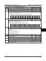
4.2 Selection of Main Circuit Peripheral Devices
Please refer to the Table 4-1 for the recommended specifications.
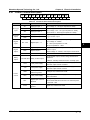
Table 4-1
HD5L series controller I/O wiring specification
Input Protection
Main Circuit
Control Circuit
Model
MCCB
Contactor
Supply Cables
Motor Cables
(A)
(A)
(mm2)
(mm2)
HD5L-2S2P2
32
20
4.0
2.5
≥0.5
HD5L-2S3P7
63
32
4.0
4.0
≥0.5
HD5L-2T3P7
40
32
4.0
4.0
≥0.5
HD5L-2T5P5
63
40
6.0
6.0
≥0.5
HD5L-2T7P5
63
40
6.0
6.0
≥0.5
HD5L-2T011
100
63
16
16
≥0.5
HD5L-2T015
125
100
25
25
≥0.5
HD5L-2T018
160
100
25
25
≥0.5
HD5L-2T022
200
125
35
35
≥0.5
HD5L-2T030
200
125
50
50
≥0.5
HD5L-4T2P2
16
10
1.5
1.5
≥0.5
HD5L-4T3P7
25
16
2.5
2.5
≥0.5
HD5L-4T5P5
32
25
4.0
4.0
≥0.5
HD5L-4T7P5
40
32
4.0
4.0
≥0.5
HD5L-4T011
63
40
6.0
6.0
≥0.5
HD5L-4T015
63
40
6.0
6.0
≥0.5
HD5L-4T018
100
63
10
10
≥0.5
HD5L-4T022
100
63
16
16
≥0.5
HD5L-4T030
125
100
25
25
≥0.5
HD5L-4T037
160
100
25
25
≥0.5
HD5L-4T045
200
125
35
35
≥0.5
(mm2)
4.3 Main Circuit Terminals and Wiring
Danger
• The bare portions of the power cables must be bound with insulation tapes.
Warning
• Ensure that AC supply voltage is the same as controller’s rated input voltage.
―16―
HD5L Series Controller
User Manual
Shenzhen Hpmont Technology Co., Ltd.
Chapter 4
Electrical Installation
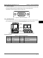
4.3.1 Terminals Description
L1 L2
L3
POWER
P1
(+) (-) BR
U
V
W
MOTOR
PE
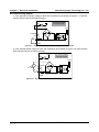
Figure 4-1 Power terminal layout of HD5L controller
Table 4-2 HD5L power terminal function description
Terminal
Function Description
Three-phase AC power input terminals
L1、L2、L3
Output terminals, connect to three-phase AC motor
U、V、W
4
P1、(+)
DC reactor connection terminals
(+)、(-)
DC supply input terminals; DC input terminals of power regenerative unit
(+)、BR
Braking resistor connection terminals
PE
Earth terminal, connect to the ground
4.3.2 Wiring Terminals
L1
L2
L3
P1
(+)
(-)
BR
U
V
W
PE
Optional EMI filter
Optional AC reactor DC reactor Braking resistor
(external)
Fuses
Supply ground
Mains supply
Figure 4-2
HD5L power terminal connection
During trial operation, make sure that the elevator will go up when the UP command is enabled.
If the elevator goes down, set the parameter F00.08 (run direction) to be the reverse value.
HD5L Series Controller
User Manual
―17―
Chapter 4
Electrical Installation
Shenzhen Hpmont Technology Co., Ltd.
4.4 Control Terminals and Wire Connection
Danger
• The control circuit is designed as ELV (Extra Low Voltage) circuit and basically isolated with the
power circuit. Do not touch the control circuit when the controller is on power.
Warning
• If the control circuit is connected to the external devices with live touchable port (SELV circuit), it
should increase an additional isolating barrier to ensure that SELV classification of external devices
not be changed.
• If connect the communication terminal of the control circuit to the PC, you should choose the
RS485/232 isolating converter which meets the safety requirement.
In order to efficiently suppress the interference to control signals, the length of signal cables
should be less than 50m and keep a distance of at least 0.3m from the power lines. Please use
twisted-pair shielded cables for analogue input and output signals.
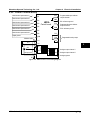
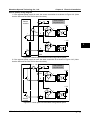
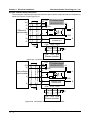
The positions of control terminal, wire jumper and SCI communication port in the control board
are shown in Figure 4-3.
Wire jumper
Wire jumper
Wire jumper CN9
CN5 and CN6
CN7 and CN8
SCI communication terminal
Control terminal
Figure 4-3 Positions of control terminal, wire jumper and SCI port in the control board
―18―
HD5L Series Controller
User Manual
Shenzhen Hpmont Technology Co., Ltd.
Chapter 4
Electrical Installation
4.4.1 Control Terminal Description
+10
AI1
AI2
AI3
DI1
DI2
GND GND AO1 AO2 -10
DI3
DI4
DI5
DI6 COM COM R1A
P24 SEL COM CME DO1 DO2 R1B R1C
Figure 4-4 Control terminal layout
Table 4-3 Control terminal function description
Item
Analogue
input
Analogue
output
Terminal
Name
Function Description
AI1
Anglogue input 1
Input voltage: 0-10V (input impedance: 34kΩ)
AI2
Anglogue input 2
Input voltage/current is selectable;
AI3
Anglogue input 3
AO1
Anglogue output 1
Output voltage/current signal: 0-10V/0-20mA;
AO2
Anglogue output 2
Programmable output
DI1-DI6
Digital input 1-6
Input voltage: -10V-10V (input impedance: 34kΩ);
Input current: 0-20mA (input impedance: 500Ω)
Programmable bipolar optional input signal
Digital
input
Input voltage: 0-30VDC
DI1-DI5 input impedance: 4.7kΩ;
4
DI6 input impedance: 1.6kΩ
Digital
output
Relay
output
Power
source
DO1
Digital output 1
DO2
Digital output 2
CME
DO1 reference ground
R1A/ R1B/ R1C Relay contact output
Programmable optical-coupled isolation, open
collector output
Output voltage: 0-30VDC, max-output current 50mA
Isolated from COM, default short connected COM
Programmable output, contact rating: 250VAC/3A or
30VDC/1A
R1B,R1C: normally closed; R1A,R1C: normally open
+10V
+10V power supply
Analogue input use +10V as reference supply,
maximum output current is 100mA
-10V
-10V power supply
Analogue input use -10V as reference supply,
maximum output current is 10mA
GND
+/-10V power
reference ground
Analogue site, isolated from COM
P24
+24V power supply
Digital input use +24V as supply, maximum output
current is 200mA
SEL
Digital input common
terminal
COM
Digital reference
ground
HD5L Series Controller
User Manual
Factory settings default SEL and P24 are connected.
Disconnected SEL and P24 when use external power
to drive DI1-DI6
Digital site, isolated from CME
―19―
Chapter 4
Electrical Installation
Shenzhen Hpmont Technology Co., Ltd.
4.4.2 Wire Jumper Description
Table 4-4 Wire jumper function and setting description on the control board
Jumper
Function and setting description
Factory setting
1
AI2 analogue input channel can select voltage or current signal.
CN5
When pin 1 and pin 2 of the CN5 are short-circuited, AI2 channel
inputs voltage signal;
CN5
3
When pin 2 and pin 3 of the CN5 are short-circuited, AI2 channel
inputs current signal.
1
AI3 analogue input channel can select voltage or current signal.
CN6
When pin 1 and pin 2 of the CN6 are short-circuited, AI3 channel
inputs voltage signal;
CN6
3
When pin 2 and pin 3 of the CN6 are short-circuited, AI3 channel
inputs current signal.
1
AO1 analogue output channel can select voltage or current signal.
CN7
When pin 1 and pin 2 of the CN7 are short-circuited, AO1 channel
outputs voltage signal;
CN7
3
When pin 2 and pin 3 of the CN7 are short-circuited, AO1 channel
outputs current signal.
1
AO2 analogue output channel can select voltage or current signal.
CN8
When pin 1 and pin 2 of the CN8 are short-circuited, AO2 channel
outputs voltage signal;
CN8
3
When pin 2 and pin 3 of the CN8 are short-circuited, AO2 channel
outputs current signal.
1
SCI communication can select proper resistance.
3 CN9
When pin 2 and pin 3 of the CN9 are short-circuited, no resistance;
CN9
When pin 1 and pin 2 of the CN9 are short-circuited, select the proper
resistance.
4.4.3 SCI Communication Terminal Description
Port pin
1
2
3
4
5
6
7
8
Port signal +5V 485+ +5V GND GND GND 485- Reserved
RJ45
Figure 4-5
―20―
1
8
SCI communication terminal and description
HD5L Series Controller
User Manual
Shenzhen Hpmont Technology Co., Ltd.
Chapter 4
Electrical Installation
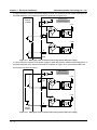
4.4.4 Control Terminal Wiring
Multi-function input terminal 1
Multi-function input terminal 2
CME
DI2
Multi-function input terminal 3
HD5L
DI3
Multi-function input terminal 4
Control board
DI4
Multi-function input terminal 5
DO2
COM
DI5
Multi-function input terminal 6
Digital ground
Shielded cable
AI 1
DI6
R1C
COM
R1B
+10
R1A
Programmable open-collector
output channel 1
DO1 reference ground
Programmable open-collector
output channel 2
DO2 reference ground
Programmable relay output
AI1
CN6
CN7
CN8
3
CN5
1
Figure 4-6
3
PE
1
GND
3
AI3
1
AI 3
4
3
AI2
1
AI 2
Analogue ground
HD5L Series Controller
DO1
DI1
AO1
Analogue output channel 1
AO2
Analogue output channel 2
GND
Analogue ground
HD5L control circuit wiring diagram
User Manual
―21―
Chapter 4
Electrical Installation
Shenzhen Hpmont Technology Co., Ltd.
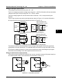
Dry contact wiring diagram
1. If the internal 24V power supply is used, the connection is as shown in Figure 4-7. (The SEL
and the P24 are short-circuited at factory)
+ 24V
P24
Dry contact connection
using internal power
SEL
+ 3.3V
+
Current
R
K
-
DI1...DI6
COM
Figure 4-7
Dry contact connection when using internal 24V power
2. If the external power supply is used, the connection is as shown in Figure 4-8. (Note that the
SEL and the P24 are not short-circuited)
P24
+ 24V
Dry contact connection
using external power
SEL
+
DC 12-30V
K
Current
R
DI1...DI6
+ 3.3V
+
-
COM
Figure 4-8
―22―
Dry contact connection when using external power
HD5L Series Controller
User Manual
Shenzhen Hpmont Technology Co., Ltd.
Chapter 4
Electrical Installation
Source (Drain) wiring diagram
1. If the external power supply is used, the source connection is as shown in Figure 4-9. (Note
that the SEL and the P24 are not short-circuited)
P24
External
controller
+ 24V
Source connection
using external power
SEL
+
DC
12-30V
1
+ 3.3V
+
R
-
DI1
+ 3.3V
+
R
6
4
-
DI6
COM
Figure 4-9
Source input connection when using external power
2. If the external power supply is used, the drain connection is as shown in Figure 4-10. (Note
that the SEL and the P24 are not short-circuited)
+
-
DC 12-30V
P24
+ 24V
Drain connection
using external power
SEL
COM
R
1
DI1
+ 3.3V
+
-
+ 3.3V
+
R
6
External
controller
DI6
Figure 4-10
HD5L Series Controller
-
Drain input connection when using external power
User Manual
―23―
Chapter 4
Electrical Installation
Shenzhen Hpmont Technology Co., Ltd.
3. If the controller’s internal 24V power supply is used, the common emitter output connection of
the NPN transistor in the external controller is as shown in Figure 4-11.
External
controller
P24
+ 24V
NPN connection
using internal power
SEL
+ 3.3V
+
R
1
-
DI1
+ 3.3V
+
R
6
-
DI6
COM
Figure 4-11
NPN signal input connection when using internal 24V power supply
4. If the controller’s internal +24V power supply is used, the common emitter output connection of
the PNP transistor in the external controller is as shown in Figure 4-12. (Note that the SEL and
the P24 are not short-circuited)
P24
+ 24V
PNP connection
using internal power
SEL
COM
1
R
DI1
+ 3.3V
+
-
+ 3.3V
+
6
External
controller
Figure 4-12
―24―
R
DI6
-
PNP signal input connection when using internal 24V power supply
HD5L Series Controller
User Manual
Shenzhen Hpmont Technology Co., Ltd.
Chapter 4
Electrical Installation
Wiring of analogue input terminal
The analogue input has three input ports: AI1-AI3.
The AI1 is voltage input and the voltage input range is 0-10V.The AI2 and the AI3 are selectable
voltage/current input, the input range are -10-+10V/0-20mA.
The input voltage signal can use the control board of internal +/-10V, or be provided by the
external.
Potentiometer
The AI1 input terminal connection and disposal are shown in Figure 4-13. And the AI2 and the
AI3 input terminal connection and disposal are shown in Figure 4-14.
Less than 50 m
Signal line winding on the
ferrite core about 2 or 3 turns
+10
AI1
Filter capacitor
Control
Control
AI1
0.022uF
Board
Board
50V
GND
GND
Ferrite core
PE
Figure 4-13
AI1 input terminal connection and disposal
Less than 50 m
Signal line winding on the
ferrite core about 2 or 3 turns
+10
Potentiometer
Control
Board
AI2/AI3
GND
PE
Figure 4-14
AI2/AI3
Filter capacitor
0.022uF
50V
Control
Board
GND
Ferrite core
AI2 and AI3 input terminal connection and disposal
The shielded cable is recommended due to the analogue input signal is electronic signal and
susceptible to external interference. The shielded cable should be no longer than 50m and the
PE should be reliable grounded. In some serious interference state, the analogue input signal
should take the advantage of the filter capacitor and the ferrite core.
Wiring of multi-function output terminal
The function output terminal DO1 and DO2 can use the controller’s internal 24V power supply or
the external power supply. The connections are as shown in Figure 4-15.
+ 24V
+ 24V
P24
DO1
DO2
Relay
coil
DO1
DO2
CME
CME
COM
COM
Using the internal 24V power supply
Figure 4-15
HD5L Series Controller
P24
User Manual
Relay
coil
+
-
DC
12-30V
Using the external power supply
DO terminal connection
―25―
4
Chapter 4
Electrical Installation
Shenzhen Hpmont Technology Co., Ltd.
4.5 I/O Terminals and Wiring Connection
HD5L series elevator controller has I/O interface board which can achieve the extension of
analogue input, digital input and relay contact output. I/O interface board is shown as Figure 4-16
and the size unit is mm.
95
65
To connect the control board
Wire jumper CN3
Wire jumper CN2 I/O interface board terminals
5
105
Figure 4-16 I/O interface board
4.5.1 Terminal Description of I/O Interface Board
AI4+ DI7
DI8
DI9 DI10 DI11 DI12
GND AI4- P24 SEL COM COM COM
R2A R3A R3B R4A
R2B R2C R3C R4B R4C
Figure 4-17 Terminal layout of I/O interface board
Table 4-5 Terminal function description of I/O interface board
Item
Analogue
input
Digital
input
Terminal
AI4+
AI4-
DI7-DI12
Name
Analogue
differential input
Digital input
7-12
R2A/R2B/R2C
Relay
output
R3A/R3B/R3C
Relay contact
output
R4A/R4B/R4C
Power
source
―26―
Function Description
Input voltage/current is selectable
Input voltage: -10V-10V (input impedance: 34kΩ);
Input current: 0-20mA (input impedance: 500Ω)
Programmable bipolar optional input signal
Input voltage: 0-30VDC
Input impedance: 4.7kΩ
Programmable output, contact rating: 250VAC/3A or
30VDC/1A
RB,RC: normally closed; RA,RC: normally open
GND
Analogue
ground
Analogue site, isolated from COM
P24
+24V power
supply
Digital input use +24V as supply, maximum output
current is 200mA
Digital input
common
terminal
Factory settings default SEL and P24 are connected.
SEL
COM
Digital
reference
ground
Disconnected SEL and P24 when use external power
to drive DI7-DI12
Digital site, isolated from CME
HD5L Series Controller
User Manual
Shenzhen Hpmont Technology Co., Ltd.
Chapter 4
Electrical Installation
4.5.2 Wire Jumper Description of I/O Interface Board
Table 4-6 Wire jumper function and setting description on the I/O interface board
Jumper
Function and setting description
Factory setting
1
AI4 analogue input channel can select voltage or current signal.
CN2
V
When pin 1 and pin 2 of the CN2 are short-circuited, AI4 channel
inputs voltage signal;
I
3
When pin 2 and pin 3 of the CN2 are short-circuited, AI4 channel
inputs current signal.
CN2
CN3
1
AI4 analogue input channel can select thermistor.
V
When pin 1 and pin 2 of the CN3 are short-circuited, AI4 channel is
for the user reference analogue input;
R
3
When pin 2 and pin 3 of the CN3 are short-circuited, AI4 channel is
for the motor over-heating detection signal input via the external
connected thermistor.
CN3
4.5.3 Terminal Connection of I/O Interface Board
4
Analogue input terminal connection
When the AI4 is used as the user reference analogue input terminal, the connection is shown as
Figure 4-18 and the AI4+ is as analogue input.
AI4+
I/O
interface
board AI4-
Analogue input
-10-+10V or
0-20mA
GND
PE
Figure 4-18
AI4 as the analogue input terminal
When the AI4 is used as the motor over-heating detection signal input terminal, the connection is
shown as Figure 4-19. The motor stator coil built-in thermistor to access the analogue input and it
should be correctly set the wire jumper.
+5V
Wire jumper setting
V
1
R
I
CN3
V
3
Figure 4-19
Thermistor
3
I/O
AI4interface
board GND
1
10k AI4+
CN2
PE
AI4 as the over-heating signal detection input terminal
Digital input terminal connection
The digital input terminals (DI7-DI12) of I/O interface board and the digital input terminals (DI1
-DI6) of control board have the same connection method. Please refer to 4.4.4 Control Terminal
for details.
HD5L Series Controller
User Manual
―27―
Chapter 4
Electrical Installation
Shenzhen Hpmont Technology Co., Ltd.
4.6 Encoder Interface Board
4.6.1 Encoder Interface Board Introduction
There are 4 kind encoder interface boards are provided for the HD5L series controller. And their
models and functions are shown as Table 4-7.
Table 4-7
Encoder interface boards
Encoder interface boards
Functions
OC encoder interface board with
frequency demultiplication (FD) output
(HD-PG2-OC-FD)
SINCOS encoder interface board with
FD output
(HD-PG5-SINCOS-FD)
Support the differential ABZ signals and the pulse FD output;
Apply to asynchronous motor closed-loop vector control (VC)
Support the SINCOS signal and the pulse FD output;
Apply to synchronous motor closed-loop vector control (VC)
Support the differential ABZ and UVW signal;
Line drive encoder interface board with
Support the pulse FD output;
FD output(HD-PG6-UVW-FD)
Apply to synchronous motor closed-loop vector control (VC)
SC encoder interface board with FD
output
(HD-PG9-SC-FD)
Support the serial communication signal;
Support the pulse FD output;
Apply to synchronous motor closed-loop vector control (VC)
The requirements of encoder interface board connection:
1. Separate encoder interface board cables from power cables, and make sure they do not go
parallel.
2. The encoder interface board cables must use independent tube and the metal enclosure must
be reliable grounded.
4.6.2 FD Description
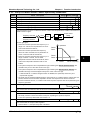
To change the FD coefficient is by shifting 6-digit FD switches. When the switch shifts to ON, it
will mean “1”, otherwise mean “0”. Converter the 6-digit binary number into decimal number, the
resulting number multiplies 2 is the FD coefficient shown as Figure 4-20.
Maximum value is “111111” which is 63*2 FD.
FD high bit
FD low bit
FD high bit
FD low bit
FD high bit
FD low bit
3 2 1
3 2 1
3 2 1
3 2 1
3 2 1
3 2 1
ON
ON
000 000:1 FD
Figure 4-20
―28―
ON
ON
000 010:2*2 FD
ON
ON
010 000:16*2 FD
Encoder interface board FD description
HD5L Series Controller
User Manual
Shenzhen Hpmont Technology Co., Ltd.
Chapter 4
Electrical Installation
4.6.3 DB15 Terminal
The HD-PG5-SINCOS-FD and the HD-PG6-UVW-FD both use the DB15 terminal. It will be well
to connect the DB15 terminal to the DB15 socket of motor encoder signal cable.
The definition of terminal number is shown as Figure 4-21.
5
1
10
15
6
11
Figure 4-21
DB15 terminal definition
4.6.4 HD-PG2-OC-FD
The OC encoder interface board with frequency demultiplication (FD) output is shown as Figure
4-22. FD switch is shown as the section 4.6.2 FD Description and the size unit is mm.
32
27
To connect
control board
1 2 3
1 2 3
FD high bit FD low bit
24.5
50
ON
Figure 4-22
PGP A+
Terminal
ON
FD switch
B+ PGP OUTA
COM A-
B- COM OUTB
OC encoder interface board with frequency demultiplication output
Terminal description
Table 4-8
Terminal
Terminal function description
Name
Terminal
Name
PGP
+12V power output
B+
Encoder B+ signal
COM
Power supply site, isolated
from GND
B-
Encoder B- signal
A+
Encoder A+ signal
OUTA
FD output A signal, NPN type OCoutput
A-
Encoder A- signal
OUTB
FD output B signal, NPN type OCoutput
HD5L Series Controller
User Manual
―29―
4
Chapter 4 Electrical Installation
Shenzhen Hpmont Technology Co., Ltd.
Encoder interface board connection
The connection of differential output encoder and open-collector output encoder are respectively
shown as Figure 4-23 and Figure 4-24.
PGP
VCC
+12V PG interface board
COM
0V
A+
A+
A-
A-
Differential
output encoder
HD-PG2-OC-FD + 5V
COM
A
GND
B+
B+
B-
B
Interface circuit
the same as A
BCOM
PE
OUTA OUTB
PE
COM
PGA
PGB
Elevator controller
Figure 4-23
Connection of differential output encoder
PGP
VCC
+12V PG interface board
COM
0V
A+
Open-collector
output encoder
HD-PG2-OC-FD + 5V
COM
A
A-
A
GND
B+
PE
B
Interface circuit
the same as A
B-
B
COM
OUTA OUTB
PE
COM
PGA
PGB
Elevator controller
Figure 4-24
―30―
Connection of open-collector output encoder
HD5L Series Controller
User Manual
Shenzhen Hpmont Technology Co., Ltd.
Chapter 4
Electrical Installation
The push-pull signal output encoder is shown as Figure 4-25.
PGP
VCC
+12V PG interface board
COM
0V
A
A+
Push-pull
output encoder
A-
B
B+
HD-PG2-OC-FD + 5V
COM
A
GND
B
Interface circuit
the same as A
B-
COM OUTA OUTB
PE
PE
COM
PGA
4
PGB
Elevator controller
Figure 4-25
HD5L Series Controller
Connection of push-pull output encoder
User Manual
―31―
Chapter 4
Electrical Installation
Shenzhen Hpmont Technology Co., Ltd.
4.6.5 HD-PG5-SINCOS-FD
30.5
55
FD
low bit
1 23
ON
ON
1 2 3
SINCOS encoder interface board with FD output is shown as Figure 4-26. FD switch is shown as
the section 4.6.2 FD Description and the size unit is mm.
44
17
FD
high bit
FD switch
FD output
terminal
OUTA
OUTB
6
COM
DB15 terminal
Figure 4-26
SINCOS encoder interface board with FD output
Terminal description
Table 4-9
DB15 terminal signal description
No.
Name
Description
No.
Name
Description
1
B-
Differential signal B-
8
B+
Differential signal B+
2
NC
Invalid
9
PGVCC
+5V power supply
3
R+
Differential signal R+
10
C+
Differential signal C+
4
R-
Differential signal R-
11
C-
Differential signal C-
5
A+
Differential signal A+
12
D+
Differential signal D+
6
A-
Differential signal A-
13
D-
Differential signal D-
7
GND
Power supply site
14、15
NC
Invalid
Table 4-10 FD output terminal signal description
―32―
No.
Name
Description
1
OUTA
FD output signal A, NPN type OC output
2
OUTB
FD output signal B, NPN type OC output
3
COM
FD output signal site, isolated from GND
HD5L Series Controller
User Manual
Shenzhen Hpmont Technology Co., Ltd.
Chapter 4
Electrical Installation
Encoder interface board connection
The connection of SINCOS encoder is shown as Figure 4-27.
PGVCC
+5V
GND
PG interface board
HD-PG5-SINCOS-FD
GND
A+
A-
SINCOS encoder
GND
A
-
B+
PG
+
BC+
CD+
D-
Interface circuit
the same as A
B
Interface circuit
the same as A
C
Interface circuit
the same as A
D
4
COM OUTA OUTB
PE
PE
COM
PGA
PGB
Elevator controller
Figure 4-27
HD5L Series Controller
User Manual
Connection of SINCOS encoder
―33―
Chapter 4
Electrical Installation
Shenzhen Hpmont Technology Co., Ltd.
4.6.6 HD-PG6-UVW-FD
OUTA
OUTB
30.5
55
FD
low bit
1 23
ON
ON
1 2 3
The line driver encoder interface board with FD output is shown as Figure 4-28. FD switch is
shown as the section 4.6.2 FD Description and the size unit is mm.
44
17
FD
high bit
FD switch
FD output
terminal
6
COM
DB15 terminal
Figure 4-28 Line driver encoder interface board with FD output
Terminal description
Table 4-11 DB15 terminal signal description
No.
Name
Description
No.
Name
Description
1
A+
Differential signal A+
9
V+
Differential signal V+
2
A-
Differential signal A-
10
V-
Differential signal V-
3
B+
Differential signal B+
11
W+
Differential signal W+
4
B-
Differential signal B-
12
W-
Differential signal W-
5
Z+
Differential signal Z+
13
PGVCC
+5V power supply
6
Z-
Differential signal Z-
14
GND
Power supply site
7
U+
Differential signal U+
15
NC
NC
8
U-
Differential signal UTable 4-12 FD output terminal signal description
―34―
No.
Name
Description
1
OUTA
FD output signal A, NPN type OC output
2
OUTB
FD output signal B, NPN type OC output
3
COM
FD output signal site, isolated from GND
HD5L Series Controller
User Manual
Shenzhen Hpmont Technology Co., Ltd.
Chapter 4
Electrical Installation
Encoder interface board connection
The connection of UVW encoder is shown as Figure 4-29.
PGVCC
+5V
PG interface board
HD-PG6-UVW-FD
GND
GND
A+
A
AB+
B-
UVW encoder
Z+
PG
ZU+
UV+
VW+
WCOM
Interface circuit
the same as A
B
Interface circuit
the same as A
Z
Interface circuit
the same as A
U
Interface circuit
the same as A
V
Interface circuit
the same as A
W
4
OUTA OUTB
PE
PE
COM
PGA
PGB
Elevator controller
Figure 4-29
HD5L Series Controller
User Manual
Connection of UVW encoder
―35―
Chapter 4
Electrical Installation
Shenzhen Hpmont Technology Co., Ltd.
4.6.7 HD-PG9-SC-FD
The serial communication encoder interface board with FD output (HD-PG9-SC-FD) supported
the Endat protocol is shown as Figure 4-30 and the size unit is mm.
To connect the control board
5
65
Terminals
5
95
105
Figure 4-30
Serial communication encoder interface board with FD output
Terminal description
DI7
DI8 PAO PBO R2A R2B R2C
+5V
P24 SEL COM COM R3A R3B R3C
C+
GND
D+
C-
A+
D-
B+
A-
B-
Figure 4-31 Terminal signal description
Table 4-13 FD output terminal signal description
Item
Digital input
FD output
Terminal
DI7-DI8
PAO
Name
Digital input 7-8
FD output
PBO
R2A/R2B/R2C
Relay output
Power
Power
Signal
Terminal
Relay contact output
R3A/R3B/R3C
Function Description
Programmable bipolar optional input signal
Input voltage: 0-30VDC; Input impedance: 4.7kΩ
FD output signal A, NPN type OC output
FD output signal B, NPN type OC output
Programmable output, contact rating: 250VAC/3A or
30VDC/1A
RB,RC: normally closed; RA,RC: normally open
P24
+24V power supply
SEL
Digital input
common terminal
COM
Digital reference
ground
Digital input use +24V as supply, maximum output
current is 200mA
Factory settings default SEL and P24 are connected.
Disconnected SEL and P24 when use external power
to drive DI7-DI12
Digital site, isolated from CME
+5V
+5V power
+5V power supply for PG
GND
Reference ground
+5V reference ground
C+/C-
CLK
CLK Differential signal C+/C-
D+/D-
Data
Data Differential signal D+/D-
Sin/Cos Signal
Differential signal A+/A-/B+/B-
A+/A-/B+/B-
FD description
The FD coefficient of HD-PG9-SC-FD is set by F16.10.
―36―
HD5L Series Controller
User Manual
Shenzhen Hpmont Technology Co., Ltd.
Chapter 4
Electrical Installation
4.7 Meet EMC Requirement of Installation
4.7.1 Correct EMC Installation
According national standards GB/T12668.3, the controller should meet the two requirements of
electromagnetic interference (EMI) and anti-electromagnetic interference. The international
standards IEC/61800-3 (VVVF drive system part 3: EMC specifications and test methods) are
identical to the national standards GB/T12668.3.
HD5L Series Controllers are designed and produced according to the requirements of
IEC/61800-3. Please install the controller as per the description below so as to achieve good
electromagnetic compatibility (EMC).
In a drive system, the controller, control equipment and sensors are installed in the same cabinet,
the electromagnetic noise should be suppressed at the main connecting points with the EMI filter
and input reactor installed in cabinet to satisfy the EMC requirements.
The most effective but expensive measure to reduce the interference is to isolate the noise
source and the noise receiver, which should be considered in mechanical system design phase.
In driving system, the noise source can be controller, braking unit and contactor. Noise receiver
can be automation equipment, encoder and sensor etc.
The mechanical/system is divided into different EMC areas according to its electrical
characteristics. The recommended installation positions are shown in Figure 4-31.
Mains power supply
Area E
Power supply control cabinet
Area C
Area A
AC reactor
Control devices (the
host PC, PLC etc.)
Area B
Sensor (temperature,
liquid level sensor)
Area B: interfaces of signal and control cables,
correct immunity level is required.
Area C: install noise sources such as input reactor,
the controller, braking unit and contactor.
EMI filter
Area D: install output EMI filter and its cable
connection parts.
HD5L controller
Area D
Area E: power supply.
Area F: install motor and its cables.
EMI filter
Earth isolated board
Manufacture machines
Mechanical system
Motor
Figure 4-31
HD5L Series Controller
Area A: install transformers of control power supply,
control devices and sensor etc.
User Manual
Area F
System wiring sketch
―37―
4
Chapter 4
Electrical Installation
Shenzhen Hpmont Technology Co., Ltd.
Remarks:
• All areas should be isolated in space to achieve electromagnetic decoupling effect.
• The minimum distance between areas should be 20cm, and use earthing bars for decoupling
among areas, the cables from different area should be placed in different tubes.
• EMI filters should be installed at the interfaces between different areas if necessary.
• Bus cable (such as RS485) and signal cable must be shielded.
4.7.2 Wiring Requirement
In order to avoid interference intercoupling, it is recommended to separate the motor cables and
the control cables from power supply cables, and keep enough distance among the cables.
Especially when the cables are laid in parallel and the cable length is long, the signal cables
should cross the power supply cables perpendicularly as shown in Figure 4-32.
Motor cables
> 30cm
> 50cm
Power or motor cables
Power cables
Signal/control cables
> 20cm
Signal/control cables
Figure 4-32
System wiring
Shielded/armoured cable: High frequency low impedance shielded cable should be used. For
example: copper net, aluminum net or iron net.
Normally, the control cables must use the shielded cables and the shielding metal net must be
connected to the metal enclosure of the controller by cable clamps as shown in Figure 4-33.
PE
Enclosure
Figure 4-33
PE
Enclosure
Correct connection of the shielded cable
4.7.3 Wiring Motor
Longer the cable between the controller and the motor is, higher the high-frequency leakage
current is, causing the controller output current to increase as well. This may affect peripheral
devices.
When the cable between the motor and the controller is longer than 100 meters, it is
recommended to install output reactor and adjust the carrier frequency as per the instruction in
Table 4-14.
―38―
HD5L Series Controller
User Manual
Shenzhen Hpmont Technology Co., Ltd.
Chapter 4
Electrical Installation
Table 4-14 Carrier frequency and the cable length between controller and motor
< 30m
30-50m
50-100m
≥ 100m
15kHz below
10kHz below
5kHz below
2kHz below
Cable length
Carrier frequency
The controller should be derated if the motor cables are too long or their cross sectional area
(CSA) is too large. The controller’s cables should be the cables with specified CSA (see Table 4-1)
because the capacitance of the cable to ground is in proportional to the cable’s CSA. If the cable
with big CSA is used, its current should be reduced. The current should be decreased by 5%
when per level of CSA is increased.
4.7.4 Ground Connections
The earth terminals PE must be connected to earth properly. The earthing cable should be as
short as possible (the earthing point should be as close to the controller as possible) and the
earthing area should be as large as possible.
The grounding resistance should be less than 10Ω.
Do not share the earth wire with other devices such as welding machines or power tools. It could
share the earthing pole, but the motor and the controller each have their own earthing pole, then
the earthing effect is better. The recommended and avoided earthing methods are respectively
shown in Figure 4-34 and Figure 4-35.
HD5L
Other devices
PE
HD5L
Other devices
PE
Dedicated earthing pole
(optimal)
Figure 4-34
HD5L
Sharing earthing pole
(good)
Recommended earthing method
Other devices
PE
HD5L
Other devices
PE
Sharing earthing pole
(not so good)
Figure 4-35
Avoided earthing method
When using more than one controllers, be careful not to loop the earth wire as shown in Figure
4-36.
HD5L
HD5L
HD5L
PE
PE
PE
HD5L
PE
Prohibited earthing method
Figure 4-36
HD5L Series Controller
User Manual
Prohibited earthing method
―39―
4
Chapter 4
Electrical Installation
Shenzhen Hpmont Technology Co., Ltd.
4.7.5 EMI Filter
The EMI filter should be used in the equipment that may generate strong EMI or the equipment
that is sensitive to the external EMI. The EMI filter should be a dual-way low pass filter through
which lower frequency current can flow while higher frequency current can hardly flow.
Function of EMI filter
1. The EMI filter ensures the equipment not only can satisfy the conducting emission and
conducting sensitivity in EMC standard but also can suppress the radiation of the equipment.
2. It can prevent the EMI generated by equipment from entering the power cable and the EMI
generated by power cable from entering equipment.
Common mistakes in using EMI filter
1. Too long the power cable is between the EMI filter and the controller
The filter inside the cabinet should be located near to the input power source. The length of the
power cables should be as short as possible.
2. Too close the input and output cables of the EMI filter
The distance between input and output cables of the filter should be as far apart as possible.
Otherwise the high-frequency noise may be coupled between the cables and bypass the filter.
Thus, the filter will become ineffective.
3. Bad earthing of the EMI filter
The EMI filter’s enclosure must be earthed properly to the metal case of the controller. In order to
achieve better earthing effect, make use of a special earthing terminal on the filter’s enclosure. If
you use one cable to connect the filter to the case, the earthing is useless for high frequency
interference. When the frequency is high, so is the impedance of cable, hence there is little
bypass effect.
The correct installation: The filter should be mounted on the enclosure of equipment. Ensure to
clear away the insulation paint between the filter case and the enclosure for good earthing
contact.
4.7.6 Conduction, Radiation and Radio Frequency Interference
Countermeasures
EMI of the controller
The controller’s operating theory means that some EMI is unavoidable. The controller is usually
installed in a metal cabinet which normally little affects the instruments outside the metal cabinet.
The cables are the main EMI source. If connect the cables according to this manual, the EMI can
be suppressed effectively.
If the controller and other control equipment are installed in one cabinet, the area rule must be
observed. Pay attention to the isolation between different areas, cable layout and shielding.
Reducing conducted interference
Please add a noise filter to suppress conducted interference on the output side. Additionally,
conducted interference can be efficiently reduced by threading all the output cables through a
grounded metal tube. And conducted interference can be dramatically decreased when the
distance between the output cables and the signal cables is above 0.3m.
―40―
HD5L Series Controller
User Manual
Shenzhen Hpmont Technology Co., Ltd.
Chapter 4
Electrical Installation
RF interference clearing
The I/O cables and the controller produce radio frequency interference. A noise filter can be
installed both on the input side and output side, and shield them with iron utensil to reduce RF
interference.
The wiring distance between the controller and the motor should be as short as possible shown in
Figure 4-37.
Metal tube
Iron box
MCCB
X
~
X
EMI filter
HD5L
EMI filter
M
X
Figure 4-37
RF interference clearing
4.7.7 Input and Output Reactor
AC input reactor
The purpose of installing an AC input reactor is: to increase the input power factor; to dramatically
reduce the harmonics on the input side at the high voltage point of common coupling and prevent
input current unbalance which can be caused by the phase-to-phase unbalance of the power
supply. An AC line reactor which will help to protect the input rectifiers also reduces external line
voltage spikes (for example the lightning!).
DC reactor
The installation of a DC reactor can increase the input power factor, improve the controller’s
overall efficiency and thermal stability, substantially eliminate the upper harmonics influence on
the controller’s performance, and considerably decrease the conducted and radiated
electromagnetic emissions from the controller.
AC output reactor
Generally speaking, when the length of the cable between controller and motor is more than
100m, it will cause leakage current and controller tripping. It suggests that the user should
consider installing an AC output reactor.
HD5L Series Controller
User Manual
―41―
4
Shenzhen Hpmont Technology Co., Ltd.
Chapter 5
Operation Instructions
Chapter 5 Operation Instructions
Danger
• Only when the controller terminal cover has been fitted can you switch on AC power source. Do not
remove the cover after power is switched on.
• Ensure the motor and the mechnical device are in the use application before the controller starts.
• Keep away from the controller if the auto-restart function is enabled at power outage.
• If changed the main control PCBA, you should correctly set the parameters before operating.
Warning
• Do not check or detect the signal during the controller operation.
• Do not randomly change the controller parameter setting.
• Please thoroughly complete all control debugging and testing, make all adjustments and conduct a full
safety assessment before switching the run command source of the controller.
• Do not touch the energy-depletion braking resistor due to the high temperature.
5.1 Function Description
Note:
1. In the following sections, you may encounter control, running and state of the controller
description many times.
2. Please read this section carefully. It will help you to correctly understand and use the functions
to be discussed.
5.1.1 Operation Mode
The operation mode defines how the controller receives run commands (start or stop command).
There are four operation modes which can be selected through function parameter F00.05.
Panel control: The run command is controlled by RUN and STOP keys of the panel; and the
run speed is set by F00.07.
Terminal analogue control: The run command is controlled by UP and DN of the terminal; and
the run speed is set by AI1-AI4 analogue input terminals.
Terminal speed control: The run command is controlled by UP and DN of the terminal; and the
run speed is set by MS1-MS3 multi-step speed terminal combination.
Communication speed control: The run command and the run multi-step speed are set by PC
communication.
HD5L Series Controller
User Manual
―43―
5
Chapter 5
Operation Instructions
Shenzhen Hpmont Technology Co., Ltd.
5.1.2 Control Mode
HD5L series controllers have three control modes which respectively are V/f control, SVC control
and VC control. (Refer to F00.01 for more detail)
5.1.3 Controller State
HD5L series controller states respectively are: Stop, Run, Motor parameters auto-tuning, Fault
alarm and Under-voltage.
Stop state: After the controller is switched on and initialized, if no run command inputs or the
stop command is given, there will be no output from U/V/W of the controller and the LCD panel
will be anti-color display STOP under the left.
Run state: The controller will start output from U/V/W terminals after it receives the run
command. And the LCD panel will be anti-color display RUN under the left.
Motor parameters auto-tuning: After set the function parameter F07.06/F10.10 as 1 or 2, the
controller will receive the run command then enter into motor parameters auto-tuning state. If the
auto-tuning process is completed, the controller will enter into stop state.
Fault alarm state: The controller has failure.
Under-voltage state: The controller is in the under-voltage.
5.1.4 Controller Running Mode
HD5L series controllers have five running modes: Auto-tuning running, MS speed running,
Inspection running, Battery-driven running and Normal running.
Auto-tuning running: Set F07.06/F10.10 = 1 or 2 and press RUN key to enter the auto-tuning
running.
MS speed running: The run speed is set by MS1-MS3 in combination or communication. This
mode is accessible when F00.05 is set as 2 or 4.
Inspection running: When inspection signal is valid, the speed will be determined by F05.08
(inspection run speed). This mode is accessible when F00.05 is set as 1, 2 or 4.
Battery-driven running: When emergency signal is valid, the speed will be determined by
F05.09 (battery driven speed). This mode is accessible when F00.05 is set as 1, 2 or 4.
Normal running: Controlled by panel (F00.05 = 0) or terminal analogue (F00.05 = 1).
―44―
HD5L Series Controller
User Manual
Shenzhen Hpmont Technology Co., Ltd.
Chapter 5
Operation Instructions
5.2 Operating Instructions
5.2.1 Panel Description
The standard HD5L series controllers are installed with LCD panel which is shown as Figure 5-1.
PRG
JOG
SHF
ENT
RUN
Figure 5-1
5
STOP
Panel of HD5L controller
There are keys on the panel and their functions, as shown in Table 5-1.
Table 5-1
Key
Key function description
Name
Function
PRG
Program/exit
Entry or exit programming key
JOG
Jog key
Reserved
RUN
Run key
In the mode of panel control, press this key to run the controller
STOP
Stop/reset key
In the mode of panel control, to stop controller and reset the fault
Multi-function key
Set certain function by F00.06
Increment key
Increase value or parameter
Decrement key
Decrease value or parameter
SHF shift key
Selecting display parameter and shift bit
ENT enter/confirm key
Enter lower menu or confirm saving the data
HD5L Series Controller
User Manual
―45―
Chapter 5
Operation Instructions
Shenzhen Hpmont Technology Co., Ltd.
5.2.2 Display State
The panel of HD5L series controller can display the parameters at stopping, running, editing and
alarming.
Note:
LCD anti-color displays: display in white on black such as STOP , RUN , F03: , 0.3 5 0 m/s etc.
1. If the parameter or the setting value is in anti-color displaying, it means that it can be changed.
Take 0.3 5 0 m/s for example, it means that the units of setting value can be changed.
2. If the state is in anti-color displaying, it means that it is in this state. Take
means that the controller is in the running state.
RUN
for example, it
Parameter display state at stopping
When the controller stops running, the panel will display stopping state and its parameter, as
shown in Figure 5-2. Other parameters (F15.08-F15.13) can be displayed by pressing
.
Ready para.
Setting speed
=0 1.5 0 0 m/s
UP
Running para.
Given speed
=0 1.3 5 9 m/s
STOP LO/RE ALM
Figure 5-2
UP
RUN LO/RE ALM
Display state of the panel
Parameter display state at running
When the controller is running, the panel will display running state and its parameter, as shown in
Figure 5-2. Other parameters (F15.02-F15.07) can be displayed by pressing
.
Four-level menu switching operation
The panel of HD5L series controller uses four-level menu configuration for parameter setting or
other operations.
Configuring mode can be displayed in 4-level menu: mode setting (first-level)→function
parameter group setting (second-level)→function parameter setting (third-level)→parameter
setting (fourth-level). The operation process is shown in Figure 5-3 and the description of the
keys is shown in Table 5-2.
―46―
HD5L Series Controller
User Manual
Shenzhen Hpmont Technology Co., Ltd.
Ready para.
Setting speed
=0 1.5 0 0 m/s
UP
PRG
PRG
STOP LO/RE ALM
Chapter 5
D:
STOP LO/RE ALM
UP
UP
STOP LO/RE ALM
F03.00:
Acc speed
用户密码
UP
STOP LO/RE ALM
PRG
Second-level menu
F03.03:
Dec speed
菜单模式
STOP LO/RE ALM
UP
Third-level menu
F03.13:
= 0 0.3 5 0 m/s3
Stop Dec jerk
UP
STOP LO/RE ALM
First-level menu
F00:
Basic parameters
用户密码
Second-level menu
UP
UP
First-level menu
F03:
Acc/Dec parameters
用户密码
PRG
F:
General function para
meters用户密码
Display Para.
菜单模式
Stop state
Operation Instructions
STOP LO/RE ALM
STOP LO/RE ALM
Third-level menu
PRG
F03.13:
Stop Dec jerk
菜单模式
UP
STOP LO/RE ALM
F03.03:
Dec speed
菜单模式
UP
Third-level menu
Fourth-level menu
STOP LO/RE ALM
5
Third-level menu
Figure 5-3 Four-level operation process
Table 5-2 Switching four-level description of the key
Key
First-level menu
PRG
Fault, return to faulty
display; Fault
cleared, return to run
or stop state display.
Return to first-level
menu
Return to second-level
menu
Do not save the present
value and return to
third-level
Enter to second-level
menu
Enter to third-level
menu
Enter to fourth-level menu
Save the present value
and return to third-level
Select function
group.
Modify No. function.
Modify the internal No. of
function group. Increase
by 1 according to the
present modified bit
Modify function value.
Increase by 1 according
to the present modified
bit
Cycle according to
Y-F-D
Decrease by 1
when press this key
one time
Modify the internal No. of
function group. Decrease
by 1 according to the
present modified bit
Modify function value.
Decrease by 1
according to the present
modified bit
Invalid
Invalid
Switch units and tens
Switch units , ten
thousands, thousands,
hundreds, tens
Cycle according to
D-F- Y
Select function
group.
HD5L Series Controller
Second-level menu
Increase by 1 when
press this key one
time
Modify No. function.
User Manual
Third-level menu
Fourth-level menu
―47―
Chapter 5
Operation Instructions
Shenzhen Hpmont Technology Co., Ltd.
Function parameter editing state
At stop, run or fault alarm state, press PRG to enter function parameter editing state (see the
description of parameter F01.00 and the user password unlock and modify of section 5.2.3), as
shown in Figure 5-4.
F03.13:
= 0 0.3 5 0 m/s3
Stop Dec jerk
F03:
Acc/Dec parameters
用户密码
UP
STOP LO/RE ALM
Figure 5-4
UP
STOP LO/RE ALM
Parameter editing state
Fault alarming state
If the controller detects a fault signal, the panel will enter the fault alarming state and LCD will
display the fault code and name and anti-color display ALM , as shown in Figure 5-5.
You can enter Group F17 to check the fault history.
E0024:
External faulty
请按键以检测其有效性
Lu:
DC bus low
请按键以检测其有效性
UP
UP
STOP LO/RE ALM
Figure 5-5
STOP LO/RE ALM
Fault alarming state
The controller can be reset by pressing STOP key, or by sending the reset commands via the
external terminal or communication reset command.
5.2.3 Panel Operation Examples
Function parameter setting
For example: To modify the setting value of the function parameter F00.07 from 1.500m/s to
1.000m/s, as shown in Figure 5-6.
F00.07:
Speed setting of pane
l菜单模式
UP
STOP LO/RE ALM
UP
F00.08:
Run direction
菜单模式
UP
UP
STOP LO/RE ALM
STOP LO/RE ALM
F00:
Basic parameters
运行方向选择
Shifting
F00.07:
= 0 1.0 0 0 m/s
Third-level menu
UP
STOP LO/RE ALM
Fourth-level menu
Third-level menu
PRG
F00.07:
= 0 1.5 0 0 m/s
F00.07:
= 0 1.5 0 0 m/s
UP
STOP LO/RE ALM
Modify setting value
F:
Ready para.
PRG General function para PRG Setting speed
=0 1.0 0 0 m/s
meters
STOP LO/RE ALM
Second-level menu
Figure 5-6
UP
STOP LO/RE ALM
UP
First-level menu
Function parameter setting
STOP LO/RE ALM
Stop state
In the setting fourth-level menu situation, if the parameter is not in anti-color displaying, it
indicates that this parameter can’t be modified. The possible reasons are as follows:
―48―
HD5L Series Controller
User Manual
Shenzhen Hpmont Technology Co., Ltd.
Chapter 5 Operation Instructions
• The function parameter can’t be modified, such as the actual detected parameters or recorded
parameters etc.
• Only when the controller stops can it modify the function parameter.
• Only input the correct password can it edit the function parameter due to the valid password.
Switching display parameters at stopping state
There are six stopping parameters(F15.08-F15.13) of the HD5L controller. For example, set the
parameter to be default value and the Figure 5-7 describes the operation of displaying
parameters.
Ready para.
Setting speed
=0 1.5 0 0 m/s
UP
Ready para.
AI1 voltage disposal
=0 1.6.0 0 V
Ready para.
DC bus voltage
=0 1.5 3 7 V
STOP LO/RE ALM
STOP LO/RE ALM
UP
F15.08 = 4
UP
STOP LO/RE ALM
F15.10 = 16
F15.09 = 14
Ready para.
Output terminal state
=0000 0000 0000 0000
UP
STOP LO/RE ALM
Ready para.
Input terminal state
=0000 0000 0000 0000
STOP LO/RE ALM
UP
F15.12 = 27
F15.11 = 26
Switching display parameters at stopping state
Figure 5-7
5
Unlock user’s password
When user set F01.00 to non-zero value and detect no press on the panel within 5 minutes, the
user’s password will be valid. The lock identification of panel will be .
The operation of unlock user’s password is as shown in Figure 5-8 which takes 4 as the user’s
password. The lock identification will be
when it successfully unlocks.
F01.00
User password
菜单模式
UP
F01.00
=0 0 0 0 0
User password
STOP LO/RE ALM
UP
Third-level menu
STOP LO/RE ALM
Fourth-level menu
F01.01
Menu mode
菜单模式
UP
STOP LO/RE ALM
Third-level menu
Figure 5-8
HD5L Series Controller
F01.00
=0 0 0 0 4
User password
UP
STOP LO/RE ALM
Input correct password
Unlock success
UP
STOP LO/RE ALM
Unlock success
Operation of unlocking user’s password
User Manual
―49―
Chapter 5
Operation Instructions
Shenzhen Hpmont Technology Co., Ltd.
Modify user’s password
If no password, directly modify the value of F01.00 according to Figure 5-9.
If there is password, you should unlock the password according to Figure 5-8. When the lock
successfully displays the
, you can set a new password according to Figure 5-9 which takes
“02004” as the new password. When the password is valid, the lock identification will be .
F01.00
User password
菜单模式
F01.01
User password
菜单模式
UP
STOP LO/RE ALM
UP
Third-level menu
STOP LO/RE ALM
Third-level menu
STOP LO/RE ALM
Shifting
F01.00
= 0 2 0 0 4
User password
UP
STOP LO/RE ALM
Fourth-level menu
UP
STOP LO/RE ALM
Modify password units
Encryption success
菜单模式
STOP LO/RE ALM
UP
Modify password thousands
Figure 5-9
UP
F01.00
=0 0 0 0 4
User password
F01.00
= 0 0 0 0 4
User password
UP
F01.00
=0 0 0 0 0
User password
STOP LO/RE ALM
F01.01
Menu mode
菜单模式
UP
STOP LO/RE ALM
Third-level menu
Modify successfully
Operation of modifying user’s password
Clear user’s password
If there is password, you should unlock according to Figure 5-8. When it successfully displays
you can clear the user’s password according to Figure 5-10.
F01.01
Menu mode
菜单模式
UP
F01.00
User password
菜单模式
STOP LO/RE ALM
UP
Third-level menu
STOP LO/RE ALM
Third-level menu
F01.01
Menu mode
菜单模式
UP
STOP LO/RE ALM
Third-level menu
Figure 5-10
―50―
F01.00
=0 0 0 0 0
User password
UP
STOP LO/RE ALM
Fourth-level menu
PW. has been cleared
菜单模式
UP
STOP LO/RE ALM
Clear password
Operation of clearing user’s password
HD5L Series Controller
User Manual
,
Shenzhen Hpmont Technology Co., Ltd.
Chapter 5
Operation Instructions
Panel self-testing
The panel of the HD5L series controller has self-testing function which facilitates periodic
inspection for itself and the keys.
The process of panel self-testing:
1. In stopping state, press
key and
key simultaneously for 2-3 seconds, the panel will
check the LCD whether works well which is as shown in Figure 5-11.
Figure 5-11
Starting panel self-testing
2. Press any key of the panel and if the state is in anti-color display, it means the key is valid. And
the correct correspondence is as shown in Figure 5-12.
During this process, if there is no press in 4-5 seconds, it will directly jump to the step 4. If the
self-check is success, it will jump to the step 3.
Please press the key
JOG
PRG
UP
SHIFT
ENTER
M
Please press the key
JOG
PRG
UP
SHIFT
ENTER
M
Please press the key
JOG
UP
PRG
SHIFT
ENTER
M
RUN
RUN
RUN
DN
STOP
DN
STOP
DN
JOG
PRG
Please press the key
JOG
UP
PRG
SHIFT
ENTER
M
Please press the key
JOG
UP
PRG
SHIFT
ENTER
M
Please press the key
JOG
UP
PRG
SHIFT
ENTER
M
RUN
RUN
RUN
DN
STOP
DN
STOP
DN
STOP
Please press the key
JOG
PRG
UP
SHIFT
ENTER
M
Please press the key
JOG
PRG
UP
SHIFT
ENTER
M
Panel self-test pass
JOG
PRG
UP
ENTER
SHIFT
M
RUN
RUN
RUN
DN
STOP
DN
STOP
DN
STOP
STOP
RUN
Figure 5-12
5
STOP
Correct correspondence of the keys and the displays
3. If all keys are valid, the panel will display “Panel self-test pass”. The “Panel self-test pass” will
auto-disappear within 3-5 seconds and back to display state before self-testing.
4. If the key is invalid, the correspondence display will not be in anti-color displaying. The panel
will display “Panel self-test fail”. The “Panel self-test fail” will auto-disappear within 3-5 seconds
and back to display state before self-testing.
The possible reasons of self-testing failure: no press within 5s or invalid key.
HD5L Series Controller
User Manual
―51―
Chapter 5
Operation Instructions
Shenzhen Hpmont Technology Co., Ltd.
Upload and download parameters
Upload: When set the function parameter F01.03 = 1, it uploads the setting value to the panel.
When the upload is finished, the panel will jump to display F01.00.
Download: When set the function parameter F01.02 = 2, it downloads the setting value from the
panel. When the download is finished, the panel will jump to display F01.03.
The upload and download parameters are as shown in.
Para. being uploaded
Upload progress:050%
=0 1.5 0 0 m/s
停机状态参数
Dnload fail
=0 1.5 0 0 m/s
Para. being dnloaded
Dnload progress:030%
=0 1.5 0 0 m/s
UP
Figure 5-13
STOP LO/RE ALM
Display upload and download parameters
Note:
1. When downloading parameters, it displays “dFAiL” which represents that the EEPROM
storage parameters of panel and the function parameters of present controller do not match.
First, you need upload the setting value of the correct function code to the EEPROM of panel,
and then you can download.
2. When upload or download parameters, the panel displays “E0022” (panel EEPROM fault). It
will jump to next function code 10 seconds later. The troubleshooting is in Chapter 8 (Page 99).
5.3 Initial Power On
It need carefully check before power is on. Please wire the controller according to the
specifications supplied by this manual.
After checking the wiring and mains supply voltage, switch on the circuit breaker and the
controller will be initialization. The panel will display as shown in Figure 5-14.
Lu:
DC bus low
请按键以检测其有效性
Hpmont Technology
UP
Figure 5-14
―52―
Ready para.
Setting speed
= 1.5 0 0 m/s
STOP LO/RE ALM
UP
STOP LO/RE ALM
Display initialing panel
HD5L Series Controller
User Manual
Shenzhen Hpmont Technology Co., Ltd.
Chapter 6
Function Introduction
Chapter 6 Function Introduction
This chapter will provide user with detail function introduction of each group.
Display Parameters:
Group D00 System State Parameters (on pages 54-55)
Group D01 Drive State Parameters (on pages 55-55)
Group D02 Analogue State Display Parameters (on pages 56-57)
Group D03 Running State Parameters (on pages 57-58)
Group D04 Encoder State Parameters (on pages 58-59)
General Function Parameters:
Group F00 Basic Parameters (on pages 59-61)
Group F01 Protection of Parameters (on pages 61-62)
Group F02 Start & Stop Parameters (on pages 62-63)
Group F03 Acceleration/Deceleration Parameters(on pages 63-64)
Group F04 Analogue Curve Parameters (on pages 64-65)
Group F05 Speed Parameters (on pages 65-67)
Group F06 Weighing Compensation Parameters (on pages 67-68)
Group F07 Asynchronous Motor Parameters (on pages 68-71)
6
Group F08 Motor Vector Control Speed-loop Parameters (on pages 71-72)
Group F09 Current-loop Parameters (on pages 72-72)
Group F10 Synchronous Motor Parameters (on pages 72-73)
Group F11 PG Parameters (on pages 73-74)
Group F12 Digital I/O Terminal Parameters (on pages 74-77)
Group F13 Analogue I/O Terminal Parameters (on pages 77-79)
Group F14 SCI Communication Parameters (on pages 79-80)
Group F15 Display Control Parameters (on pages 80-81)
Group F16 Enhance Function Parameters (on pages 81-82)
Group F17 Fault Protect Parameters (on pages 82-85)
Group F18 PWM Parameters (on pages 85-85)
Group F19 Reserved
Group F20 Reserved
Manufacturer Function Parameters (on page 85)
HD5L Series Controller
User Manual
―53―
Chapter 6
Function Introduction
Shenzhen Hpmont Technology Co., Ltd.
6.1 Group D: Display Parameters
Group D is state display parameters. The users can directly check the state parameters by
checking the function code of Group D.
6.1.1 Group D00 System State Parameters
Code
D00.00
Name Description
Range【factory setting】
【actual value】
Controller series
Display HD5L controller series.
D00.01
【actual value】
DSP software version
Display the DSP software version.
D00.02
【actual value】
DSP special software version
Display the DSP special software version.
D00.03
【actual value】
Panel software version
Display the panel software version.
D00.04
【actual value】
Elevator running state
Display the elevator running state in 16-bit binary. As following:
Bit15: battery driven run
Bit14: MS terminal 3
Bit13: MS terminal 2
Bit12: MS terminal 1
0: no
0: invalid
0: invalid
0: invalid
1: yes
1: valid
1: valid
1: valid
Bit11: down forced Dec.
input
Bit10: up forced Dec.
input
Bit9: contactor
feedback input
Bit8: brake feedback
input
0: invalid
0: invalid
0: invalid
0: invalid
1: valid
1: valid
1: valid
1: valid
Bit7-bit4: reserved which means “0”
D00.05
Bit3: analogue run
Bit2: MS run
Bit1: inspection run
Bit0: controller enable
0: no
0: no
0: no
0: disenable
1: yes
1: yes
1: enable
1: yes
123
Controller rated current
【actual value】
Display the controller rated current.
D00.06
【actual value】
Controller state
Display the controller state in 16-bit binary. As following:
Bit15: reserved
Bit13: stop signal
Bit12: contactor output
0: no stop signal
0: invalid
1: stop signal
1: valid
Bit11: brake output
Bit10: ready to run
Bit9: speed arrived
Bit8: auto-tuning
0: invalid
0: not ready
0: no
0: no in auto-tuning
1: valid
1: be ready
1: yes
1: in auto-tuning
Bit7: run at
zero-speed
Bit6: zero-speed
signal
Bit5&Bit4: acceleration/deceleration/constant
0: not at zero-speed
0: invalid
00: constant
01: acceleration
11: reserved
10: deceleration
1: at zero-speed
1: valid
Bit3: DN
Bit2: UP
Bit1: run/stop
Bit0: controller fault
0: no
0: no
0: stop
0: no fault
1: yes
1: run
1: fault
1: yes
123
―54―
Bit14: reserved
HD5L Series Controller
User Manual
Shenzhen Hpmont Technology Co., Ltd.
Chapter 6
Function Introduction
6.1.2 Group D01 Drive State Parameters
Code
D01.00
Name Description
Range【factory setting】
【actual value】
Control mode
Display the cotrol mode.
D01.01
Setting speed (m/s)
【actual value】
Display the setting speed.
D01.02
Setting speed (after acceleration/deceleration) (m/s)
【actual value】
Display the speed which is disposed by acceleration/deceleration S curve.
D01.03
Feedback speed (m/s)
【actual value】
Display the elevator’s actual speed.
D01.04
Setting frequency
【actual value】
Display the setting frequency.
D01.05
Setting frequency (after acceleration/deceleration)
【actual value】
Display the frequency (after acceleration/deceleration).
D01.06
Output frequency
【actual value】
Display the output frequency.
D01.07
【actual value】
Setting Rpm
Display the setting Rpm.
D01.08
【actual value】
Running Rpm
Display the running Rpm.
D01.09
Reserved
D01.10
Output voltage
【actual value】
Display the output voltage.
D01.11
【actual value】
Output current
Display the output current.
D01.12
【actual value】
Output torque
Display the output torque which is the relative percentage of the motor rated torque.
D01.13
【actual value】
Output power
Display the output power which is the relative percentage of the motor rated power.
D01.14
【actual value】
DC bus voltage
Display the DC bus voltage.
D01.15-D01.16 Reserved
HD5L Series Controller
User Manual
―55―
6
Chapter 6
Function Introduction
Shenzhen Hpmont Technology Co., Ltd.
6.1.3 Group D02 Analogue State Display Parameters
Code
D02.00
Name Description
Range【factory setting】
【actual value】
AI1 voltage
Display AI1 input voltage.
D02.01
【actual value】
AI1 voltage (after disposal)
Display A1 input voltage which is disposed by the gain, bias and filter.
D02.02
【actual value】
AI2 voltage
Display AI2 input voltage. When AI2 selects current input, the corresponding relations are:
- 10.00V corresponds to 0mA, and 10.00V corresponds to 20mA.
D02.03
【actual value】
AI2 voltage (after disposal)
Display A2 input voltage which is disposed by the gain, bias and filter.
D02.04
【actual value】
AI3 voltage
Display AI3 input voltage. When AI3 selects current input, the corresponding relations are:
- 10.00V corresponds to 0mA, and 10.00V corresponds to 20mA.
D02.05
【actual value】
AI3 voltage (after disposal)
Display A3 input voltage which is disposed by the gain, bias and filter.
D02.06
【actual value】
AI4 voltage
Display AI4 input voltage. When AI4 selects current input, the corresponding relations are:
- 10.00V corresponds to 0mA, and 10.00V corresponds to 20mA.
D02.07
【actual value】
AI4 voltage (after disposal)
Display A4 input voltage which is disposed by the gain, bias and filter.
D02.08
AO1 output
【actual value】
Display AO1 output. When AO1 selects current output, the corresponding relations are:
0V corresponds to 0mA, and 10.00V corresponds to 20mA.
D02.09
AO2 output
【actual value】
Display AO2 output. When AO2 selects current output, the corresponding relations are:
0V corresponds to 0mA, and 10.00V corresponds to 20mA.
―56―
HD5L Series Controller
User Manual
Shenzhen Hpmont Technology Co., Ltd.
Chapter 6
Function Introduction
6.1.4 Group D03 Running State Parameters
Code
D03.00
Name Description
Range【factory setting】
【actual value】
Heatsink temperature
Display heatsink temperature.
D03.01
【actual value】
Input terminal state
Display input terminal state. Each bit(binary) of this function parameter stands for different physical
sources which are in the below table.
• 0: Multi-function input terminals are not connected with common terminals.
• 1: Multi-function input terminals are connected with common terminals.
D03.02
Bit11
Bit10
Bit9
Bit8
Bit7
Bit6
Bit5
Bit4
Bit3
Bit2
Bit1
Bit0
DI12
DI11
DI10
DI9
DI8
DI7
DI6
DI5
DI4
DI3
DI2
DI1
123
Output terminal state
【actual value】
Display output terminal state. Each bit(binary) of this function parameter stands for different physical
sources which are in the below table.
• Positive logic: 0 stands for invalid while 1 stands for valid.
• Negative logic: 0 stands for valid while 1 stands for invalid.
D03.03
Bit5
Bit4
Bit3
Bit2
Bit1
Bit0
RLY4
RLY3
RLY2
RLY1
DO2
DO1
123
MODBUS state
【actual value】
Display MODBUS communication state.
6
0: Normal.
1: Communication timeout.
2: Incorrect data frame head.
3: Incorrect data frame checking.
4: Incorrect data frame content.
D03.04
Total time at power-on
【actual value】
D03.05
Total running time
【actual value】
D03.04 display total time at power-on; D03.05 displays total running time. The unit is hour.
D03.06
【actual value】
Running times
Display the running times of the controller.
D03.07
【actual value】
Present fault
Display the present fault.
HD5L Series Controller
User Manual
―57―
Chapter 6
Function Introduction
Shenzhen Hpmont Technology Co., Ltd.
6.1.5 Group D04 Encoder State Parameters
Code
D04.00
Name Description
Range【factory setting】
【actual value】
C phase value of SINCOS encoder
Display the actual AD sample value of SINCOS encoder C phase.
D04.01
【actual value】
D phase value of SINCOS encoder
Display the actual AD sample value of SINCOS encoder D phase.
D04.02
【actual value】
A phase value of SINCOS encoder
Display the actual AD sample value of SINCOS encoder A phase.
D04.03
【actual value】
B phase value of SINCOS encoder
Display the actual AD sample value of SINCOS encoder B phase.
D04.04
UVW state of UVW encoder
【actual value】
Display the UVW state of UVW encoder.
D04.05
Electrical angle
【actual value】
D04.06-D04.07 Reserved
D04.08
Pulses of PG
【actual value】
Displaying number of encoder pulses can be used to check the encoder is connected correctly.
If the encoder is connected correctly, when the motor is rotated, D04.08 value is incremented or
decremented in accordance with the running direction.
D04.09-D04.11
―58―
Reserved
HD5L Series Controller
User Manual
Shenzhen Hpmont Technology Co., Ltd.
Chapter 6
Function Introduction
6.2 Group F: General Function Parameters
6.2.1 Group F00 Basic Parameters
Code
F00.00
Name Description
Range【factory setting】
Motor type
0,1【0】
0: Asynchronous motor.
1: Synchronous motor.
F00.01
Control mode
0-2【2】
0: V/f control. Constant voltage/frequency ratio control.
• It is applicable for special elevator occasion. This mode does not need the encoder and its
control effect is not so good as the vector control.
• When select V/f control, please properly set the V/f control parameter of Group F07 to achieve
proper efficiency.
1: SVC control. Sensorless vector control. It is only applicable for the asynchronous motor.
2: Closed-loop vector control. Sensor vector control.
• Closed-loop vector and applicable for elevator high accuracy of speed control. In generally the
elevator will take this mode.
Note:
1. V/f and SVC control are applicable for the motor without installing encoder which are one
temporary running mode when the elevator is in inspection running.
2. When select SVC or closed-loop vector control mode, you should do motor parameter
auto-tuning.
Auto-tuning process: Correctly set the motor nameplate parameters (F07.00-F07.04 / F10.00
-F10.05), then start the motor parameter auto-tuning to obtain the right parameters.
Meanwhile set vector control parameters of Group F08 to achieve excellent vector control
efficiency.
F00.02
Elevator rated speed
0.100-4.000【1.500m/s】
The elevator nominal rated speed.
• All speed setting value in the function parameters must not exceed this value.
F00.03
Controller max output frequency
5.00-100.00【50.00Hz】
It defines the maximum frequency that the controller is allowed to output.
• It should be careful to set reasonable parameters according to the nameplate of the motor and the
actual operating conditions.
F00.04
Traction machine mechanical parameters
10.0-6000.0【60.0】
It defines the relationship between the elevator speed and the motor rotation speed.
• The traction machine mechanical parameters are calculated based on the traction machine
parameters. They determine the control precision and must be correctly set.
The elevator speed and motor rotation speed relationship is shown below:
Motor rotation speed (rpm) F00.04
×
Elevator speed (m⁄s) =
1000
60
The formula for calculating motor mechanical parameters is as below:
π×D
F00.04 =
i × Winding mode
D: Diameter of motor (mm);
i: Dec. rate;
Winding mode: The way that the hoist cable is wound, set according to the actual elevator setting.
HD5L Series Controller
User Manual
―59―
6
Chapter 6
Function Introduction
Code
F00.05
Shenzhen Hpmont Technology Co., Ltd.
Name Description
Range【factory setting】
Operating mode
0-5【0】
0: Panel control.
• Controlled by pressing the RUN or STOP key of the panel. Set the run speed in F00.07.
1: Terminal analogue control.
• The run command is controlled by UP and DN of the terminal; and the run speed is set by analogue
input terminals.
2: Terminal MS control.
• The run command is controlled by UP and DN of the terminal; and the run speed is set by MS1-
MS3 multi-step speed terminal combination.
3: Reserved.
4: SCI control.
• The run command and the run multi-step speed are set by PC communication.
5: Reserved.
F00.06
M-key function
0,1【0】
0: Disable.
1: UP/DN switch.
F00.07
Speed setting of panel
0.000-F00.02【1.500m/s】
When F00.05 = 0, it set the objective speed at running.
F00.08
Run direction
0,1【0】
0: The same as run command.
1: Opposite to run command.
―60―
HD5L Series Controller
User Manual
Shenzhen Hpmont Technology Co., Ltd.
Chapter 6
Function Introduction
6.2.2 Group F01 Protection of Parameters
Code
F01.00
Name Description
Range【factory setting】
User password
00000-65535【00000】
XXXXX: To enable the password protection function, set any non-zero number as the password.
• Once the password is set, and detect that there is no press on the panel within 5 minutes, the
user’s password will be valid.
• It is necessary to input correct password if you want to change the parameters. Otherwise you can
not change any parameter via panel, but only check.
00000: The factory setting and no user’s password.
• If the user unlocks the password, it means clearing the user’s password.
• To unlock, change and clear the user’s password, see section 5.2.3.
F01.01
Menu mode
0,1【0】
0: Full menu mode. All function parameters can be displayed in this menu.
1: Checking menu mode. Only different from factory setting parameters can be displayed.
F01.02
Parameter initialization
0-3【0】
0: No operation. The controller is in regular parameter read/write state.
• Whether can change the parameter it depends on the user’s password state and the actual
operating conditions.
1: Restore to factory settings.
• Except Group F01, F07.00-F07.14, Group F10, Group F11, F15.00, F17.11-F17.27, Group
F18 and Group Y.
• Operation steps: If set F01.02 = 1, press
to ensure and the parameters are restored to
factory settings. The panel dispalys “loading defualt para.”. Then the panel will display
parameters in stop state after finish restoring to factory setting.
2: Parameter download.
• Except Group F01, F17.11-F17.27, Group F18 and Group Y.
• Motor parameters, encoder parameters and magnetic pole angle etc. will be downloaded.
Record the original parameters such as motor parameters, encoder parameters and magnetic
pole angle etc. Or restart parameter auto-tuning.
3: Clear fault information. The fault history of F17.11-F17.27 will be clear.
F01.03
Panel EEPROM parameter initialization
0,1【0】
0: No operation. The controller is in regular parameter read/write state.
1: Parameter upload. Upload the present function code settings to the panel EEPROM parameter.
Note: Group F01, F17.11-F17.27, Group F18 and Group Y do not upload.
HD5L Series Controller
User Manual
―61―
6
Chapter 6
Function Introduction
Shenzhen Hpmont Technology Co., Ltd.
6.2.3 Group F02 Start & Stop Parameters
Speed
F02.08
F00.02
Objective speed
F02.03
Time
0
Run command
Contactor output
Controller is in
running
Brake
At zero-speed
running
F02.00
F02.01 F02.02
Code
F02.00
F02.05 F02.06 F02.07
F02.04
Name Description
Range【factory setting】
Start delay time
0.000-4.999【0.000s】
When the controller receives the run command, it will wait for the delay time set by F02.00 and then
start running.
• When controlled by panel (F00.05 = 0), F02.00 is invalid.
F02.01
Brake open delay time
0.000-4.999【0.000s】
It defines the time interval from controller’s zero-speed running to output brake-open command.
• This function enables the controller to enter running state before the brake open, so as to alleviate
the impact at start.
F02.02
Retention time of start zero-speed
0.000-4.999【0.500s】
F02.02 defines the retention time from brake-open to output with speed. During the retention time, the
motor has output torque, which makes more comfortable.
• When F06.00 set 4(No weighing auto-compensation is used), the value of F02.02 should be
exceeded 0.5s.
F02.03
Start speed
0.000-0.400【0.000m/s】
It defines the initial speed required for starting the controller.
• The start speed, when properly set, can minimize the start jerk.
F02.04
Retention time of start speed
0.000-4.999【0.000s】
The start time is the time in which the controller runs at start speed (F02.03).
F02.05
Brake close delay time
0.000-4.999【0.000s】
It defines the time interval from controller’s zero-speed running to output brake-closed command.
F02.06
Retention time of stop zero-speed
0.000-4.999【0.000s】
When stopping, the motor runs at zero-speed and has output torque during the retention time, which
makes more comfortable.
F02.07
Contactor close delay time
0.000-4.999【0.000s】
It defines the running contactor delay release time after the run command is revoked.
―62―
HD5L Series Controller
User Manual
Shenzhen Hpmont Technology Co., Ltd.
Code
F02.08
Chapter 6
Name Description
Function Introduction
Range【factory setting】
Start ramp time
0.000-2.000【0.000s】
The start ramp time is the time that elevator takes to accelerate from zero to the rated speed (F00.02).
• When F02.08 is set as 0, the elevator starts from start speed directly.
F02.09
Reserved
6.2.4 Group F03 Acceleration/Deceleration Parameters
Code
Name Description
Range【factory setting】
F03.00
Acceleration speed
0.020-9.999【0.700m/s2】
F03.01
Start Acc jerk
0.020-9.999【0.350m/s3】
F03.02
End Acc jerk
0.020-9.999【0.600m/s3】
F03.03
Deceleration speed
0.020-9.999【0.700m/s2】
F03.04
Start Dec jerk
0.020-9.999【0.600m/s3】
F03.05
End Dec jerk
0.020-9.999【0.350m/s3】
F03.00-F03.05 adjust the elevator speed
via S-curve which can cushion the shock
at elevator start/stop and improve riding
comfort.
Objective
speed
F03.02
F03.00
• Acc jerk: The change ratio of acceleration.
• See the right figure for the adjustment of
S-curve.
Speed
F03.04
F03.03
F03.13
F03.01
F03.05
Time
0
6
• The S-curve becomes steeper when parameter values are raised;
• The S-curve becomes slower when parameter values are decreased.
F03.06
Inspection Acc speed
0.020-9.999【0.200m/s2】
It defines the Acc speed of elevator at the inspection running mode.
F03.07
Inspection Dec speed
0.020-9.999【1.000m/s2】
It defines the Dec speed of elevator at the inspection running mode.
F03.08
Battery driven Acc speed
0.020-9.999【1.000m/s2】
It defines the Acc speed of elevator at the battery driven mode.
F03.09
Battery driven Dec speed
0.020-9.999【1.000m/s2】
It defines the Dec speed of elevator at the battery driven mode.
F03.10
Asynchronous motor auto-tuning Acc speed
0.020-9.999【0.100m/s2】
It defines the deceleration time of emergency stop.
F03.11
Asynchronous motor auto-tuning Dec speed
0.020-9.999【0.100m/s2】
It defines the deceleration time of emergency stop.
F03.12
Abnormal Dec speed
0.020-9.999【1.000m/s2】
It defines the deceleration time of emergency stop.
F03.13
0.020-9.999【0.350m/s2】
Stop Dec jerk
It defines the deceleration time of emergency stop.
F03.14
Asynchronous motor field-weakening optimization
0-2【0】
0: No field-weakening optimization.
1: Optimize according to voltage.
2: Optimize according to current.
When set to 1 or 2, it can reduce the current noise and improve the dynamic performance of
asynchronous motor.
HD5L Series Controller
User Manual
―63―
Chapter 6
Function Introduction
Code
Shenzhen Hpmont Technology Co., Ltd.
Name Description
F03.15
Field-weakening Kp
F03.16
Field-weakening Ki
F03.17
Field-weakening voltage limit
Range【factory setting】
0-5000【4000】
0-5000【1000】
4000-5000【4126】
F03.15-F03.17 is uesd to adjust the effect of asynchronous motor field-weakening so that user need
not regulate them usually.
F03.18
Reserved
F03.19
Sincos encoder CD phase learning
0,1【0】
0: Learning.
1: Not learning.
F03.20
Reserved
6.2.5 Group F04 Analogue Curve Parameters
Code
F04.00
Name Description
Range【factory setting】
Reference curve
0000-1111【0000】
Units: AI1 characteristic curve selection.
Tens: AI2 characteristic curve selection.
Hundreds: AI3 characteristic curve selection.
Thousands: AI4 characteristic curve selection.
Ten thousands: Pulse input characteristic curve selection.
Each bit setting:
• 0: Line 1.
• 1: Line 2.
F04.01
Line 1 minimum reference
F04.02
Corresponding value of line 1 minimum reference
F04.03
Line 1 maximum reference
F04.04
Corresponding value of line 1 maximum reference
F04.05
Line 2 minimum reference
F04.06
Corresponding value of line 2 minimum reference
F04.07
Line 2 maximum reference
F04.08
0.0-F04.03【0.0%】
0.0-100.0【0.0%】
F04.01-100.0【100.0%】
0.0-100.0【100.0%】
0.0-F04.07【0.0%】
0.0-100.0【0.0%】
F04.05-100.0【100.0%】
Corresponding value of line 2 maximum reference
0.0-100.0【100.0%】
F04.01-F04.04 define the line 1. F04.05-F04.08 define the line 2.
• Both line 1 and line 2 can independently achieve positive and negative characteristics as shown in
following figure.
Positive and negative characteristics of line
F04.04
F04.08
Reference corresponding value
Analogue
(reference)
F04.02
F04.06
F04.01
F04.05
―64―
F04.03
F04.07
F04.02
F04.06
Reference corresponding value
Analogue
(reference)
F04.04
F04.08
F04.01
F04.05
F04.03
F04.07
HD5L Series Controller
User Manual
Shenzhen Hpmont Technology Co., Ltd.
Chapter 6
Function Introduction
6.2.6 Group F05 Speed Parameters
Code
Name Description
Range【factory setting】
F05.00
Multi-speed 0
0.000-F00.02【0.000m/s】
F05.01
Multi-speed 1
0.000-F00.02【0.000m/s】
F05.02
Multi-speed 2
0.000-F00.02【0.000m/s】
F05.03
Multi-speed 3
0.000-F00.02【0.000m/s】
F05.04
Multi-speed 4
0.000-F00.02【0.000m/s】
F05.05
Multi-speed 5
0.000-F00.02【0.000m/s】
F05.06
Multi-speed 6
0.000-F00.02【0.000m/s】
F05.07
Multi-speed 7
0.000-F00.02【0.000m/s】
F05.00-F05.07 define the MS running speed which use in MS run mode. F00.02 defines the elevator
rated speed.
F05.08
Inspection run speed
0.000-0.630【0.200m/s】
It defines the elevator’s running speed in the inspection mode.
F05.09
Battery driven run speed
0.000-F00.02【0.100m/s】
It defines the elevator’s running speed in the battery driven run mode.
F05.10
Up forced Dec detection value
0.0-100.0 (F00.02)【97.0%】
It defines the speed detection value at the forced
switch action.
• After forced switch act, the running speed exceeds
Dec detection value, and decelerate to F05.22
(creeping speed) according to F03.12 (abnormal
Dec speed).
Shaft top space
Top floor
Up forced
Dec switch
Contact board
6
Car
• Properly set this parameter to avoid climbing
elevator at elevator up.
F05.11
Down forced Dec detection value
0.0-100.0 (F00.02)【97.0%】
To avoid plunging elevator at elevator down. Refer to parameter F05.10.
HD5L Series Controller
User Manual
―65―
Chapter 6
Function Introduction
Code
Shenzhen Hpmont Technology Co., Ltd.
Name Description
Range【factory setting】
F05.12
FDT1
0.0-100.0 (F00.02)【90.0%】
F05.13
FDT2
0.0-100.0 (F00.02)【90.0%】
F05.14
FDT1 delay level
F05.15
FDT2 delay level
When running speed is lower than one speed
(F05.12 + F05.14) as figure’s FL, ON indicating
signal will be output till the running speed is lower
than F05.12.
0.0-100.0 (F00.02)【1.0%】
0.0-100.0 (F00.02)【1.0%】
Elevator speed
FL
F05.14
F05.12
• Refer to parameter F05.12 and F05.14 about
F05.13 and F05.15.
Time
DO
ON
OFF
ON
FL = F05.12 + F05.14
F05.16
FAR range
The pulse signal will be output if the controller’s
output frequency is within the FAR range. As
shown in the right figure.
Time
0.0-20.0【1.0%】
Elevator
speed
Refernece
speed
F05.16
Time
DO
Time
F05.17
Over-speed setting
F05.18
Over-speed detection time
80.0-120.0(F00.02)【115.0%】
0.0-2.0s【0.2】
When the elevator actual speed exceeds F05.17 setting value and the duration time exceeds F05.18
setting value, the controller alarms E0032 fault (motor over speed).
• Set F05.18 as 0, the controller does not detect motor over speed fault.
F05.19
Detected value of speed deviation
F05.20
Detected time of speed deviation
0.0-30.0(F00.02)【20.0%】
0.0-2.0【1.0s】
When the deviation of setting speed (after Acc/Dec) and motor actual run speed exceeds F05.19
setting value and the duration time exceeds F05.20 setting value, the controller alarms E0018 fault
(excessive speed deviation).
• Set F05.19 or F05.20 as 0, the controller does not detect the excessive speed deviation fault of
motor.
F05.21
Reserved
F05.22
Creeping speed
0.000-0.400【0.050m/s】
It defines the running speed at the forced Dec run.
F05.23-F05.25 Reserved
―66―
HD5L Series Controller
User Manual
Shenzhen Hpmont Technology Co., Ltd.
Chapter 6
Function Introduction
6.2.7 Group F06 Weighing Compensation Parameters
Code
F06.00
Name Description
Range【factory setting】
Pre-torque selection
0-4【4】
The pre-torque function can output the load balancing torque in advance to avoid reverse and reduce
the start impact.
0: No pre-torque function.
1: Analogue setting. Output balancing torque according to the input analog weight signal.
2: DI setting. Output balancing torque according to the input digital weight signal.
3: Digital pre-torque. If no weighing device is at the elevator, you can use the digital pre-torque mode.
• Then adjust the pre-torque digital setting parameter to make the elevator complete excitation
before open brake, therefore improve the starting comfort.
• Compensation value = Pre-torque bias - Pre-torque digital setting.
4: No weighing auto-compensation. Suitable for all PG.
5: Asynchronous motor zero-serve auto-compensation.
Speed instruction +
Speed feedback
+
+
Torque
limit
ACR
M
Filter diposal
AI
Digital
WD1
weigh signal WD2
WD3
WD4
DI weigh signal select
(F06.08-F06.11)
F06.07(Pre-torque digital setting)
No weighing
auto-compensation
Torque
Bias
Gain
(F06.01
-
F06.06)
F06.00 = 0
F06.00 = 1
F06.00 = 2
6
F06.00 = 3
Car
F06.00 = 4
Counter weight
Analogue
weigh signal
ASR
No weighing adjust
(F06.14-F06.16)
F06.01
Up pre-torque bias
0.0-100.0【50.0%】
F06.02
Down pre-torque bias
0.0-100.0【50.0%】
Pre-torque bias = (Elevator counter weight – Car weight)/ Rated weight.
F06.03
Up electrical pre-torque gain
0.000-9.000【1.000】
F06.04
Up brake pre-torque gain
0.000-9.000【1.000】
F06.05
Down electrical pre-torque gain
0.000-9.000【1.000】
F06.06
Down brake pre-torque gain
F06.07
Pre-torque digital setting
0.000-9.000【1.000】
-100.0-100.0【10.0%】
At no weighing device, set the pre-torque value via changing the value of F06.07.
F06.08
DI weighing signal 1
0.0-100.0【10.0%】
F06.09
DI weighing signal 2
0.0-100.0【30.0%】
F06.10
DI weighing signal 3
0.0-100.0【70.0%】
F06.11
DI weighing signal 4
0.0-100.0【90.0%】
When digital weighing signal termianl input is enabled, its value is the percentage of rated load.
For example: If DI weighing signal 1 is enabled, it expresses that the present load is F06.08% of the
rated load.
• If numbers of terminals are enabled simultaneously, the max number terminal will be considered as
the valid one.
HD5L Series Controller
User Manual
―67―
Chapter 6
Function Introduction
Code
Shenzhen Hpmont Technology Co., Ltd.
Name Description
Range【factory setting】
F06.12
Reserved
F06.13
Reserved
F06.14
No weighing current coefficient
F06.15
No weighing speed-loop KP
1-9999【2000】
F06.16
No weighing speed-loop KI
1-9999【2000】
0-9999【3000】
F06.14-F06.16 are used to adjust the effect of no weighing auto-compensation (F06.00 = 4).
• The system’s response can be expedited through increasing F06.14-F0616, but system’s
oscillation and overshoot may occur if the value of F06.14-F0616 is too high.
• Generally, it can smoothly start elevator via adjusting F06.14 when debugging.
• Increase F06.14 so as to avoid sliding vehicle at starting moment. Decrease F06.17 so as to
avoid shake at starting moment.
F06.17-F06.20 Reserved
6.2.8 Group F07 Asynchronous Motor Parameters
R1
Ll
R2
I1
Ll
I2
1-S
R2
S
U1
Io
Lm
R1 = F07.07 (Stator resistance)
R2 = F07.08 (Rotor resistance)
Io = F07.11 (Excitation current)
Ll = F07.09 (Leakage inductance)
Lm = F07.10 (Mutual inductance)
S = Slip ratio
The relationship among rated torque current, excitation current and motor’s rated current is as
follows:
Rated torque current = F07.05 × F07.02
Excitation current F07.11 = �1 − F07.052 × F07.02
Mutual inductance F07.10 =
Code
F07.00
F07.01
2√3π × F07.03 × F07.11
Name Description
− F07.09
Range【factory setting】
Asynchronous motor rated power
0.2-400.0kW
【Depend on controller model】
F07.01
Asynchronous motor rated voltage
0V-Controller rated voltage
【Depend on controller model】
F07.02
Asynchronous motor rated current
0.0-999.9A
【Depend on controller model】
F07.03
―68―
Asynchronous motor rated frequency
1.00-100.00【50.00Hz】
HD5L Series Controller
User Manual
Shenzhen Hpmont Technology Co., Ltd.
Code
Chapter 6
Name Description
F07.04
Asynchronous motor rated Rpm
F07.05
Asynchronous motor power factor
Function Introduction
Range【factory setting】
1-24000【1440rpm】
0.001-1.000
【Depend on controller model】
F07.06
Asynchronous motor parameter auto-tuning
0-2【0】
0: No action.
1: Motor static auto-tuning.
2: Motor rotation auto-tuning.
Motor auto-tuning:
• In the process of motor static auto-tuning, the stator resistance (F07.07), rotor resistance (F07.08)
and leakage inductance (F07.09) will be auto-measured and written into corresponding parameters
automatically.
• For mutual inductance (F07.10) and excitation current (F07.11),
• If at static auto-tuning (F07.06 = 1), it will auto calculate according to F07.05 and F07.02, then
write the result into F07.10 and F07.11;
• If at rotation auto-tuning (F07.06 = 2), the motor will be at rotation state and the auto-measured
value will be written into F07.10 and F07.11.
• When the motor is in rotation state, the oscillation and even the overcurrent might occur. In this
case, please press the STOP key to stop auto-tuning and then properly adjust the F07.21
(oscollation-suppression mode) and F07.22 (oscollation-suppression coefficient) to mitigate the
possible oscillation.
Note: The auto-tuning is enabled only in panel control mode (F00.05 = 0).
Auto-tuning procedures:
6
1.Input correct motor parameters as per its nameplate (F07.00-F07.04).
2.When F07.06 is set as 2, please set the proper Acc speed(F03.10) and Dec speed (F03.11) and
make sure the motor is disconnected with the load for security.
3.Set F07.06 as 1 or 2 firstly, then press the
key, and therewith press RUN key to start
auto-tuning. The LCD will display “Motor para. auto-tuning”.
4.When the auto-tuning is completed, the panel will return to stop display state and the F07.06 will be
reset to 0.
F07.07
Asynchronous motor stator resistance
0.000-65.535Ω
【Depend on controller model】
F07.08
Asynchronous motor rotor resistance
0.000-65.535Ω
【Depend on controller model】
F07.09
Asynchronous motor leakage inductance
0.0-6553.5mH
【Depend on controller model】
F07.10
Asynchronous motor mutual inductance
0.0-6553.5mH
【Depend on controller model】
F07.11
Asynchronous motor excitation current
0.0-999.9A
【Depend on controller model】
F07.12
Asynchronous motor of core saturation coefficient 1
0.00-0.50【0.50】
F07.13
Asynchronous motor of core saturation coefficient 2
0.00-0.75【0.75】
F07.14
Asynchronous motor of core saturation coefficient 3
0.00-1.20【1.20】
HD5L Series Controller
User Manual
―69―
Chapter 6
Function Introduction
Code
Shenzhen Hpmont Technology Co., Ltd.
Name Description
F07.15
Asynchronous motor torque boost
F07.16
Asynchronous motor torque boost end-point
In order to compensate the torque
drop at low frequency, the controller
can boost the voltage so as to boost
the torque.
F07.16 is relative to percentage of
motor rated frequency (F07.03).
Range【factory setting】
0.1-30.0【0.1%】
0.1-50.0 (F07.03)【2.0%】
Voltage
F07.01
Boosted value
Voltage of manual
torque boost
0
F07.16max
F07.03 Frequency
F07.16max = 50% F07.03
F07.17
Asynchronous motor of slip compensation gain
F07.18
Asynchronous motor of slip compensation filter time
0.0-300.0【100.0%】
0.1-10.0【0.1s】
F07.19
Asynchronous motor of slip compensation limitation
0.0-250.0【200.0%】
The motor’s slip changes with the load torque, which results in the variance of motor speed. Through
slip compensation (the controller will auto adjust its output frequency according to the motor load
torque) to reduce the influence.
• In driving state (the actual speed is lower than the setting
speed) and in generating state (the actual speed is higher
than the setting speed), the slip compensation gain
(F07.17) should be increased gradually.
• The value of auto slip compensation depends on the
motor’s rated slip, consequently make sure the motor’s
rated frequency (F07.03) and rated Rpm (F07.04) are set
correctly.
Slip
Positive slip
compensation
-100%
Range of slip compensation = Slip compensation limit
(F07.19) × Rated slip.
100% Load
Negative slip
compensation
Rated slip = F07.03 - F07.04 × Np / 60.
• Np is the number of motor pole pairs.
F07.20
AVR function
0-2【1】
0: No action.
1: Action all the time.
2: No action in deceleration process.
• The output voltage can be regulated to maintain constant via AVR. Thus, normally the AVR function
should be enabled, especially when the input voltage is higher than the rated voltage.
• In deceleration process, if the F07.20 = 0 or F07.20 = 2, the running current will be a little higher;
while if the F07.20 =1, the motor will decelerate steadily and the current will be smaller.
F07.21
Asynchronous motor of oscillation-suppression mode
0,1【0】
0: Oscillation suppression is dependent on the motor’s exciting current component.
1: Oscillation suppression is dependent on the motor’s torque current component.
F07.22
Asynchronous motor of oscillation-suppression coefficient
0-200【100】
This function is used to damp oscillation when output current is continually unstable.
This function helps to keep the motor running smoothly through correctly adjusting the setting of
F07.22.
―70―
HD5L Series Controller
User Manual
Shenzhen Hpmont Technology Co., Ltd.
Chapter 6
Function Introduction
6.2.9 Group F08 Motor Vector Control Speed-loop Parameters
Code
Name Description
Range【factory setting】
F08.00
Low speed ASR Kp
F08.01
Low speed ASR KI
1-9999【500】
0-9999【500】
F08.02
High speed ASR Kp
1-9999【500】
F08.03
High speed ASR KI
F08.04
ASR PI swithcing frequency 1
0.00-50.00【10.00Hz】
F08.05
ASR PI swithcing frequency 2
0.00-50.00【15.00Hz】
0-9999【500】
The parameters of F08.00-F08.05 and F08.07 comfirm the PID parameters of ASR. The structure of
ASR is shown in figure.
Error
Frequency command +
Frequency feedback
Torque current
setting
PID
Torque limit
As the right figure:
• When the controller operates with frequency in a
range of 0-F08.04, the PI parameters of vector
control are F08.00 and F08.01;
• When the controller operates with frequency
above the value of F08.05, the PI parameters of
vector control are F08.02 and F08.03;
• When the controller operates with frequency in a
range of F08.04-F08.05, P is the linear
interpolation between F08.00 and F08.02, while I
is the linear interpolation between F08.01 and
F08.03.
PI parameter
F08.00 /
F08.01
F08.02 /
F08.03
6
0
F08.05 Frequency
F08.04
• The system’s response can be expedited through increasing the ASR KP (F08.00, F08.02), but
oscillation may occur if the value of KP is too high.
• The system’s response can be expedited through increasing the ASR KI (F08.01, F08.03), but
oscillation and high overshoot happen easily if the value of KI is too high.
• If F08.01/F08.03 = 0 and the integral function is disabled, the speed-loop works only as a
proportional regulator.
• Generally, the KP should be adjusted firstly to the maximum on condition that the system does not
vibrate, and then the KI should be adjusted to shorten the response time without overshoot.
• It need increase KP and KI, on condition that shorter dynamic response time is required during low
frequency operation.
F08.06
ASR integral limitation
0.0-200.0 (Motor rated
current)【180.0%】
It is used to limit the maximum value of the vector control speed-loop integral.
F08.07
ASR differential time
0.000-1.000【0.000s】
It defines the vector control speed-loop differential time.
• Generally, it doesn’t need to set F08.07 except for expediting the dynamic response.
• There isn’t speed-loop differential when F08.07 = 0.
F08.08
ASR output filter time
0.000-1.000【0.008s】
It is used to filter the output of ASR regulator.
• When F08.08 = 0, the speed-loop filter is disabled.
HD5L Series Controller
User Manual
―71―
Chapter 6
Function Introduction
Code
Shenzhen Hpmont Technology Co., Ltd.
Name Description
F08.09
UP electrical torque limitation
F08.10
DN electrical torque limitation
F08.11
UP regenerative torque limitation
F08.12
DN regenerative torque limitation
Range【factory setting】
0.0-200.0 (F07.02)【180.0%】
F08.09-F08.12 are the relative percentage of
motor rated current (F07.02).
As the right figure:
• The bigger torque output, the bigger curren
toutput.
• If the torque is too big, over-current is easy to
occur.
Output torque
Positive
Down
F08.12
F08.09
Motor Rpm
F08.10
F08.11
Up
Negative
• If the torque is too small, the run speed and
the Acc/Dec speed may deviate from the
setting value.
6.2.10 Group F09 Current-loop Parameters
Code
Name Description
Range【factory setting】
F09.00
Current-loop KP
1-4000【500】
F09.01
Current-loop KI
1-4000【500】
F09.00 and F09.01 are the PI regulator parameter of current ring (ACR).
• Increasing F09.00 or F09.01 can fasten the system dynamic response to the output torque, while
decreasing F09.00 or F09.01 can build up system stability.
• Too big F09.00 or F09.01 makes the system apt to oscillate, while too small F09.00 or F09.01
affects the system torque output.
F09.02
Current-loop output filter time
0.000-1.000【0.000s】
F09.03-F09.07 Reserved
6.2.11 Group F10 Synchronous Motor Parameters
Code
F10.00
Name Description
Range【factory setting】
Synchronous motor type
0,1【0】
0: IPM.
1: SPM.
F10.01
F10.02
F10.03
Synchronous motor rated power
Synchronous motor rated voltage
Synchronous motor rated current
0.2-400.0kW
【Depend on controller model】
0-Controller rated voltage
【Depend on controller model】
0.0-999.9A
【Depend on controller model】
F10.04
Synchronous motor rated frequency
F10.05
Synchronous motor rated rpm
F10.06
Synchronous motor stator resistance
F10.07
Synchronous motor quadrature axis inductance
0.0-999.9【0.0mH】
F10.08
Synchronous motor direct axis inductance
0.0-999.9【0.0mH】
―72―
1.00-100.00【19.20Hz】
1-24000【96rpm】
0.000-9.999【0.000Ω】
HD5L Series Controller
User Manual
Shenzhen Hpmont Technology Co., Ltd.
Code
F10.09
F10.10
Name Description
Synchronous motor Back EMF
Chapter 6
Function Introduction
Range【factory setting】
0-Controller rated voltage
【380V】
Synchronous motor of angle auto-tuning
0-2【0】
0: No action.
1: Static auto-tuning.
2: Rotation auto-tuning.
• Refer to section 7.1.3 about parameter auto-tuning.
F10.11
Synchronous motor static auto-tuning voltage setting
0.0-100.0 (F10.02)【100.0%】
If synchronous motor alarms over-current at static auto-tuning, the setting value should be smaller.
F10.12
Synchronous motor initial angle
0.0-359.9【0.0°】
F10.13
Synchronous motor of Z pulse initial angle
0.0-359.9【0.0°】
F10.14
Synchronous motor SINCOS encoder C amplitude
F10.15
Synchronous motor SINCOS encoder C zero-bias
0-9999【2048】
F10.16
Synchronous motor SINCOS encoder D amplitude
0-9999【2048】
F10.17
Synchronous motor SINCOS encoder D zero-bias
0-9999【2048】
F10.18
Sincos encoder CD phase
0-9999【2048】
0,1【0】
0: C phase ahead of the D phase.
1: D phase ahead of the C phase.
Note: At the motor parameter auto-tuning , the F10.18 can be self-learning whitout manual
changes.
F10.19
Reserved
F10.20
Synchronous performance optimization
0-65535【0】
Bit0-Bit1: Reserved
Bit2: Optimization for detecting speed
0: No optimization.
1: Optimization.
Bit3-Bit15: Reserved
6.2.12 Group F11 PG Parameters
In elevator application, the PG is necessary for the motor. Please refer to section 4.6 for PG.
Code
F11.00
Name Description
Range【factory setting】
HD5L PG interface board
1-4【4】
1: HD-PG2-OC-FD is valid. Only for asynchronous motor.
2: HD-PG6-UVW-FD is valid. Only for synchronous motor.
3: HD-PG5-SINCOS-FD is valid. Only for synchronous motor.
4: HD-PG9-SC-FD is valid. Only for synchronous motor. (support Endat)
F11.01
PG P/R
F11.02
PG direction setting
1-9999【2048】
0,1【0】
It defines the connection sequence of PG whether the same as that of the drive-motor connection.
• In order to change the connection of AB two phases of the PG, you can change this parameter.
0: The same direction.
1: The reverse direction.
HD5L Series Controller
User Manual
―73―
6
Chapter 6
Function Introduction
Code
F11.03
Shenzhen Hpmont Technology Co., Ltd.
Name Description
Range【factory setting】
PG signal filter coefficient
0x00-0x77【0x11】
Units: Low-speed filter coefficient.
Tens: High-speed filter coefficient.
F11.04
The protocol of serial communication PG
0-9【0】
0: Endat.
1: Rotary transformer protocol.
2-9: Reserved.
F11.05
Detecting time of PG wire disconnection
0.00-2.00s【1.00】
F11.05 specifies the duration time for detecting PG wire disconnection fault.
The controller detects the PG wire disconnection and the duration time exceed F11.05, then the
controller alarms E0031 fault (PG disconnection).
• No detection will be conducted when F11.05 is set as 0.
6.2.13 Group F12 Digital I/O Terminal Parameters
Code
F12.00
Name
Description
Input terminal filter time
Range【factory setting】
0.000-1.000【0.010s】
This function code is to define filter time of digital input termianl and to set input terminal sensibility.
• The input terminals are susceptible to interference which will result in misoperation so that you
could increase this parameter setting value. However, too long filter time will affect adjustment
sensibility.
F12.01
DI1 terminal function
000-134【1】
F12.02
DI2 terminal function
000-134【2】
F12.03
DI3 terminal function
000-134【3】
F12.04
DI4 terminal function
000-134【4】
F12.05
DI5 terminal function
000-134【5】
F12.06
DI6 terminal function
000-134【6】
F12.07
DI7 terminal (I/O interface board terminal) function
000-134【0】
F12.08
DI8 terminal (I/O interface board terminal) function
000-134【0】
F12.09
DI9 terminal (I/O interface board terminal) function
000-134【0】
F12.10
DI10 terminal (I/O interface board terminal) function
000-134【0】
F12.11
DI11 terminal (I/O interface board terminal) function
000-134【0】
F12.12
DI12 terminal (I/O interface board terminal) function
000-134【0】
Note: When hundreds is set as 0, it means normally open input; while set as 1 it means
normally closed input.
0: Disable. It disables the terminal’s function. The controller ignores the signal input via this terminal.
• The unwanted terminal is recommended to be set as 0 so as to avoid wrong connection or
action.
1: Controller enabled. (EN)
• When enabled, the controller is enabled to run;
• When disabled, the controller is disabled to run and will be in auto stop state.
• When no terminal selects this function, it defaults that the controller is at enabled state.
―74―
HD5L Series Controller
User Manual
Shenzhen Hpmont Technology Co., Ltd.
Code
Name
Chapter 6
Description
Function Introduction
Range【factory setting】
2,3: UP/DN.
• You can set control terminal to control the controller’s up and down.
UP Terminal
DN Terminal
0
0
Stop
Selection
0
1
Down
1
0
Up
1
1
Stop
123
4-6: MS1-MS3.
• You can achieve 8-step speed running curve via terminals logic combination, as follow table.
MS3 Terminal
MS2 Terminal
MS1 Terminal
Multi-speed setting
0
0
0
Multi-speed 0 (F05.00)
0
0
1
Multi-speed 1 (F05.01)
0
1
0
Multi-speed 2 (F05.02)
0
1
1
Multi-speed 3 (F05.03)
1
0
0
Multi-speed 4 (F05.04)
1
0
1
Multi-speed 5 (F05.05)
1
1
0
Multi-speed 6 (F05.06)
1
1
1
Multi-speed 7 (F05.07)
7: Inspection input (INS).
6
• If enabled, elevator will do inspection running.
• This signal, when used together with UP/DN (No. 2 or No. 3 function) command, can control the
elevator to go up or down during inspection.
8: Battery-driven input (BAT).
• If enabled, elevator will enter battery-driven running state.
9: Contactor feedback input (CSM).
10: Brake feedback input (BSM).
11-14: Weighing signal input 1-4 (WD1-WD4).
• The switch weight signals can be input through this terminal. Based on these signals, the
controller sets the torque bias and starts the elevator stably.
• Select among WD1-WD4 according to the actual number of weighing devices and set the load
of switches based on the setting of F6.08-F6.11 (DI weighing signal 1-4).
• If many terminals are enabled, the max No. terminal will be enabled.
• For example: When WD1 and WD2 are enabled simultaneously, only WD2 is the valid one.
15: Motor over-heating input (OH).
16: Fault reset input (RST).
• Upon controller fault alarms, you can reset the fault by this terminal.
• The function of RST terminal is the same as the STOP key on the panel.
17: Up forced Dec input (UPF).
18: Down forced Dec input (DNF).
19-33: Reserved.
34: External fault (EXT).
• The fault signal of external equipment can be input through this terminal, so that controller can
monitor that equipment and respond accordingly. When the controller receives the EXT signal,
E0024 fault (external faulty) will be displayed.
HD5L Series Controller
User Manual
―75―
Chapter 6
Function Introduction
Code
F12.13
Name
Shenzhen Hpmont Technology Co., Ltd.
Description
Range【factory setting】
MS in combination of filter time
0.000-2.000【0.010s】
This parameter defines the MS in combination of filter time to make up for the time error of MS input
terminals.
• Change this parameter value according to the change asynchronous level of numbers of MS input
terminals.
F12.14
Reserved
F12.15
DO1 terminal function
F12.16
DO2 terminal function
F12.17
RLY1 relay function
F12.18
RLY2 relay (I/O interface board relay) function
0-19【0】
F12.19
RLY3 relay (I/O interface board relay) function
0-19【0】
F12.20
RLY4 relay (I/O interface board relay) function
0-19【0】
0-19【2】
0-19【3】
0-19【14】
0: Disable. The output terminals will be at no function state and no any action.
1: Controller is ready.
• Signal ON will be output if controller has no error.
2: Controller is running.
• Indication signal will be output if controller is at running state.
3: Controller is at zero-speed running.
• ON signal will be output if controller output speed is zero but at running state.
4: Zero-speed.
• ON signal will be output if controller output speed is zero.
5: Contactor output control.
• This function is used to open/close the output contactor.
6: Brake output control.
• This function is used to open/close the brake.
7,8: FDT1, FDT2.
• Refer to parameters F05.12-F05.13.
9: Speed arrived signal (FAR).
• The indication signal will be output when the controller’s output frequency is within the FAR
range. The detect range is set by F05.16 (FAR range).
• The indication signal will be output too after the controller stops.
10: Up signal output.
• When the elevator is at up running, the controller will output ON signal.
11: Down signal output.
• When the elevator is at down running, the controller will output ON signal.
12: Under-voltage.
• ON signal will be output when the controller is during under-voltage state.
13: Reserved.
14: Controller fault.
• ON signal will be output when the controller is faulty.
15: Elevator stop.
• When the elevator stops, the controller will stop and output an 2s pulse. The controller will
disable the running command according to this signal.
16-19: Reserved.
F12.21
Output terminal logic setting
00-0x3F【0】
It defines that each bit (binary) of this function represents different physical sources.
• Positive logic: When multi-function input terminals are connected to corresponding common port,
―76―
HD5L Series Controller
User Manual
Shenzhen Hpmont Technology Co., Ltd.
Code
Name
Chapter 6
Description
Function Introduction
Range【factory setting】
this logic is enabled. Otherwise the logic is disabled.
• Negative logic: When multi-function input terminals are connected to corresponding common port,
this logic is disabled. Otherwise the logic is enabled.
Bit5
Bit4
Bit3
Bit2
Bit1
Bit0
RLY4
RLY3
RLY2
RLY1
DO2
DO1
• 0 represents positive logic, while 1 represents negative logic.
F12.22-F12.24 Reserved
6.2.14 Group F13 Analogue I/O Terminal Parameters
Code
Name Description
Range【factory setting】
F13.00
AI1 function
0-2【0】
F13.01
AI2 function
0-2【0】
F13.02
AI3 function
0-2【0】
F13.03
AI4 function
0-3【0】
0: Disable.
I/O interface board
1: Speed setting.
2: Weighing signal.
V
I
R
V
6
3
AI4-
CN3
1
Thermistor
CN2
3
• Refer to parameters F17.01 and F17.02 about the
thermistor.
AI4+
1
• Connect the electronic thermistor embedded
motor stator coils to the controller’s analogue
input, as the right figure.
+5V
10k
3: Motor over-heating signal input (only AI4 enabled).
• AI1 input range: 0-10V.
• AI2-AI4 input range: -10-+10V.
F13.04
AI1 bias
F13.07
AI2 bias
F13.10
AI3 bias
F13.13
AI4 bias
F13.05
AI1 gain
F13.08
AI2 gain
F13.11
AI3 gain
F13.14
AI4 gain
F13.06
AI1 filter time
F13.09
AI2 filter time
F13.12
AI3 filter time
F13.15
-100.0-100.0【0.0%】
-10.00-10.00【1.00】
0.01-10.00【0.05s】
AI4 filter time
When select AI1-AI4 as open-loop frequency setting source, the relationship between the analogue
input and the analogue value after compulting is shown as figure:
Analogue
actual value
Analogue
input filtering
Analogue input gain
Analogue input bias
Analogue value
after computing
• The formula of analogue input gain and bias and analogue value is: Y=kX+b
• Here: Y is the analogue value after computing, X is the value before adjusting, k is the analogue
input gain (F13.05, F13.08, F13.11, F13.14), b is the analogue input bias (F13.04, F13.07,
F13.10, F13.13).
HD5L Series Controller
User Manual
―77―
Chapter 6
Function Introduction
Code
Shenzhen Hpmont Technology Co., Ltd.
Name Description
Range【factory setting】
• F13.06, F13.09, F13.12 and F13.15 define the source filter time. It is used to filter the analogue
signal.The bigger the constant, the higher the immunity level, but the response time is prolonged
with the increase of this constant. That is, the smaller the constant, the shorter the response time,
but the lower the immunity level.
F13.16
AO1 terminal output function
0-9【0】
F13.17
AO2 terminal output function
0-9【0】
0: Disable.
1: Running speed (0-max output speed).
2: Setting speed (0-max output speed).
Note:
1. At up, up limit of No. 1 and No. 2 function is corresponding to 10V, while down limit is
corresponding to 5V;
2. At down, up limit of No. 1 and No. 2 function is corresponding to 0V, while down limit is
corresponding to 5V.
3: Output current (0-twice of controller rated current).
4: Output voltage (0-1.2 times of controller rated voltage).
5: DC bus voltage (0-2.2 times of controller rated voltage).
Note: Up limit of No. 3-5 functions is corresponding to max output voltage 10V.
6: AI1 input (0-10V).
7: AI2 input (-10-10V/0-20mA).
8: AI3 input (-10-10V/0-20mA).
9: AI4 input (-10-10V/0-20mA).
Note: When the negative voltage of No. 7-9 function is as input, the AO will output its
absolute value.
F13.18
AO1 bias
-100.0-100.0【0.0%】
F13.19
AO1 gain
0.0-200.0【100.0%】
• This parameter is used to realise the proportional relation adjustment of AO1 analogue output.
• The formula is: Y=kX+b
• Y is actual output value, X is output value before being adjusted, k is analogue output gain
(F13.19), b is analogue output bias (F13.18).
The relationship between analogue output and bias is shown as following figure.
Value after regulating (V)
100%
F13.18=50%
F13.18=0
50%
0
10
Value before regulating (V)
The relationship between analogue output and gain is shown as following figure.
―78―
HD5L Series Controller
User Manual
Shenzhen Hpmont Technology Co., Ltd.
Code
Chapter 6
Name Description
Function Introduction
Range【factory setting】
Value after regulating (V)
100%
F13.19=200%
F13.19=100%
0
5
10
Value before regulating (V)
F13.20
AO2 bias
-100.0-100.0【0.0%】
F13.21
AO2 gain
0.0-200.0【100.0%】
Refer to parameters F13.18 and F13.19.
6.2.15 Group F14 SCI Communication Parameters
Refer to Appendix B (Page 129) for the communication function.
Code
F14.00
Name Description
Data format
Range【factory setting】
0-5【0】
0: 1-8-2 format, no parity, RTU.
1: 1-8-1 format, even parity, RTU.
6
2: 1-8-1 format, odd parity, RTU.
3: 1-7-2 format, no parity, ASCII.
4: 1-7-1 format, even parity, ASCII.
5: 1-7-1 format, odd parity, ASCII.
F14.01
Baud rate selection
0-5【3】
0: 1200bps.
1: 2400bps.
2: 4800bps.
3: 9600bps.
4: 19200bps.
5: 38400bps.
F14.02
Local address
0-247【2】
When F14.02 = 0, it means broadcast address.
F14.03
Host PC response time
F14.04
Detection time of communication timeout
0-1000【0ms】
0.0-1000.0【0.0s】
When the time at no communication data exceeds the setting time of F14.04, it will be considered as
E0028 fault (SCI timeout faulty).
• When F14.04 = 0, it will not detect communication time out.
F14.05
Detection time ofcommunication error
0.0-1000.0【0.0s】
When the time at communication error exceeds the setting time of F14.05, it will be considered as
E0029 fault (SCI faulty).
• When F14.05 = 0, it will not detect the communication error.
F14.06-F14.47 Reserved
HD5L Series Controller
User Manual
―79―
Chapter 6
Function Introduction
Shenzhen Hpmont Technology Co., Ltd.
6.2.16 Group F15 Display Control Parameters
Code
F15.00
Name Description
Range【factory setting】
Language selection
0,1【0】
It defines the displaying language on the LCD panel.
0: Chinese.
1: English.
2-9: Reserved.
F15.01
LCD panel display contrast
1-10【5】
To select LCD display contrast.
F15.02
Run display parameter 1 set
F15.03
Run display parameter 2 set
0-32【5】
0-32【6】
F15.04
Run display parameter 3 set
0-32【10】
F15.05
Run display parameter 4 set
0-32【11】
F15.06
Run display parameter 5 set
0-32【0】
F15.07
Run display parameter 6 set
0-32【0】
F15.08
Stop display parameter 1 set
0-32【4】
F15.09
Stop display parameter 2 set
0-32【14】
F15.10
Stop display parameter 3 set
0-32【16】
F15.11
Stop display parameter 4 set
0-32【26】
F15.12
Stop display parameter 5 set
0-32【27】
F15.13
Stop display parameter 6 set
0-32【0】
The panel displays parameters which difine the run state (F15.02-F15.07) and stop state (F15.08-
F15.13).
• It can be cycling displayed by
key on the panel.
• Each display parameter of content can be set corresponding to 32 states.
• For instance: when set F15.08 as 7, the stop display parameter is setting Rpm at initial power on.
0: Disable.
1: Controller rated current.
17: AI2 voltage.
2: Controller state.
18: AI2 voltage (after disposal).
3: Operate channel.
19: AI3 voltage.
4: Setting speed.
20: AI3 voltage (after disposal).
5: Setting speed. (after Acc/Dec)
21: AI4 voltage.
6: Output frequency.
22: AI4 voltage (after disposal).
7: Setting Rpm.
23: AO1 output.
8: Actual Rpm.
24: AO2 output.
9: Reserved.
25: Heatsink temperature.
10: Output voltage.
26: Input terminal state.
11: Output current.
27: Output terminal state.
12: Output torque.
28: MODBUS state.
13: Output power.
29: Total time at power on (hour).
14: DC bus voltage.
30: Total running time (hour).
15: AI1 voltage.
31, 32: Reserved.
16: AI1 voltage (after disposal).
―80―
HD5L Series Controller
User Manual
Shenzhen Hpmont Technology Co., Ltd.
Chapter 6
Function Introduction
6.2.17 Group F16 Enhance Function Parameters
Code
F16.00
Name Description
Range【factory setting】
Zero-speed running signal delay time
0.00-10.00【0.30s】
It defines the delay time from the controller at zero-speed run state to zero-speed run signal output.
F16.01
Zero-speed signal delay time
0.00-10.00【0.30s】
It defines the delay time from the controller at zero-speed state to zero-speed signal output.
F16.02
Current keep time after stop command
0-9999【0ms】
To eliminate the motor current noise at stop, when the brake is over, the cut-off run signal will reduce
the current to zero after the time defined by F16.02.
F16.03
Fan control mode
0-2【0】
It defines the fan control mode. If there is over-heat protection, the fan will run all the time.
0: Auto stop.
• The fan runs all the time when the controller is in running state. After the controller stops for the
time set by F16.04, the fan will auto stop if there isn’t over-heat protection.
1: Immediately stop.
• The fan runs all the time when the controller is in running state, but stops when the controller
stops.
2: Run when power on.
• The fan runs continuously after the controller is switched on.
F16.04
Fan keep time
F16.05
Brake unit action voltage
0.0-600.0【30.0s】
380-750V
【Depend on controller
model】
For 380V voltage class controller, the braking voltage range is 630-750V.
For 220V voltage class controller, the braking voltage range is 380-450V.
Note: The braking action enable only in the controller run state.
F16.06
Contator fault detect time
F16.07
Multi-speed inspection select
0.1-10.0【2.0s】
0-7【0】
When the digital input terminals are not enough, the combinations of MS1-MS3 can achieve the
inspection run.
• When there is digital input terminal set as inspection terminal INS (No. 7 function), only need set
F16.07 as 0 to enter terminal inspection run.
• When there isn’t digital input terminal set as inspection terminal INS (No. 7 function), the inspection
run can be achieved via the combination of MS1-MS3.
• When the value of MS1-MS3 is equal to the value of F16.07, enter MS inspection run at MS run
speed (F05.00-F05.07).
Note: When the MS run speed (F05.00-F05.07) exceeds 0.630m/s, run at 0.630m/s.
F16.08
Zero-speed threshold
0.001-0.010【0.003m/s】
When the present run speed does not exceed F16.08, the system run speed will be condidered as 0.
After zero-speed delay signal, the zero-speed signal will be output.
F16.09
Selection at motor overheat fault
0,1【0】
0: When detect that the motor is overheated, report E0020 (motor overheated) after motor stop.
1: When detect that the motor is overheated, report E0020 (motor overheated) at once.
F16.10
The coefficient of frequency demultiplication of
1-256【1】
HD-PG9-SC-FD
To set the coefficient of frequency demultiplication of HD-PG9-SC-FD.
HD5L Series Controller
User Manual
―81―
6
Chapter 6
Function Introduction
Code
Shenzhen Hpmont Technology Co., Ltd.
Name Description
Range【factory setting】
F16.11
Synchronous motor static auto-tuning and current limit
F16.12
Delay time of run output signal
20-200【120%】
0.00-1.00【0.00s】
Note: F16.12 is used to delay the drive controller running (multifunction output is set to the
2nd function) signals so as to control the elevator controller to open the brake.
F16.13
UPS running direction auto-determine enable
0,1【0】
0: Not enable.
1: Enable. In the UPS mode, the controler will not run in the direction given by the terminal and
auto-detemine the the elevator light-load running direction. In the UPS mode, the controler will
automatically up, and down, and then run according to the light-load direction of detemining.
F16.14
Running minumum current limit
F16.15
Running minumum detect time
0-100 (F07.11)【20%】
0.0-5.0【0.0s】
When the elevator run current is less than F16.14 and duratuon exceed F16.05, the controller will
alarm E0025 fault (running current too small).
F16.14-F16.24 Reserved
6.2.18 Group F17 Fault Protect Parameters
Motor overheated fault (F17.00-F17.02)
It can connect the electronic thermistor embedded motor stator coils to the controller’s analogue
input AI4 in order to protect motor overheating. The connection is shown as 4.5.3 of Terminal
Connection of I/O Interface Board.
Code
Name Description
F17.00
Input voltage at motor overheated
F17.01
Thermistor type
Range【factory setting】
0.00-10.00【0.00V】
0-2【0】
0: Does not detect the motor overheating (NC).
1: Positive charateristic (PTC).
• When AI4 input is exceeded F17.00, the controller will alarm E0020 fault (motr overheated).
2: Negative charateristic (NTC).
• When AI4 input is less than F17.00, the controller will alarm E0020 fault (motr overheated).
Note: Only when correctly set CN2 and CN3 of I/O interface board will do the motor overheated
detection.
F17.02
Threshold resistance at motor overheated
0-10.0【5.0kΩ】
Input and output phase loss fault (F17.03-F17.06)
Code
Name Description
Range【factory setting】
F17.03
The detect base of lack of input
0-100【30%】
F17.04
The detect time of lack of input
0.0-5.0【1.0s】
F17.03 value is a percentage of the controller’s rated voltage.
When the controller detects certain input voltage not hit the preset detect base (F17.03) and exceed
the preset detect time (F17.04), the controller will alarm E0015 fault (lack of input).
• When F17.03 or F17.04 is set as 0 or in the battery driven run mode, the controller will not detect
input phase loss fault.
―82―
HD5L Series Controller
User Manual
Shenzhen Hpmont Technology Co., Ltd.
Code
Chapter 6
Name Description
Function Introduction
Range【factory setting】
F17.05
The detect base of lack of output
0-100【20%】
F17.06
The detect time of lack of output
0.0-20.0【3.0s】
F17.05 value is a percentage of the controller’s rated current.
When the controller detects certain output current not hit the preset detect base (F17.05) and exceed
the preset detect time (F17.06), the controller will alarm E0016 fault (lack of output).
• When F17.05 or F17.06 is set as 0, the controller will not detect output phase loss fault.
Motor fault (F17.07)
Code
F17.07
Name Description
Range【factory setting】
Motor overload protect factor
20.0-110.0【100.0%】
The motor overload protection factor can be set as 100% when the controller drives a motor of the
same power class.
To protect the motor when the motor power is smaller than the standard matched power, you need to
set a proper motor overload protection factor (F17.07). The factor can derive from the following
formula:
Motor rated current (F07.02 or F10.03)
Motor overload protect factor (F17.07) =
× 100%
Controller rated output current
Fault auto-reset function and fault relay action (F17.08-F17.10)
Auto reset function enables the controller to reset the fault as per the preset times (F17.08) and
interval (F17.09).
6
The following faults do not have the auto reset function:
E0008: Power module faulty
E0021: Control board EEPROM faulty
E0010: Brake unit faulty
E0023: Parameter setting faulty
E0013: Soft start failed
E0024: External faulty
E0014: Current detect faulty
E0036: Contactor faulty
Code
Name Description
F17.08
Fault auto reset times
F17.09
Fault auto reset interval
Range【factory setting】
0-100【0】
2.0-20.0【5.0s/times】
When F17.08 = 0, it means “auto reset” is disabled and the protective device will be activated in case
of fault.
• If no other fault is detected within 5 minutes, the auto reset count will be automatically cleared.
• On condition of external fault reset, auto reset count will be cleared.
F17.10
Fault relay action select
00-11【00】
Units: During auto reset
• 0: Fault relay doesn’t act.
• 1: Fault relay acts.
Tens: During DC bus low
• 0: Fault relay doesn’t act.
• 1: Fault relay acts.
Note: It need preset the relay function as No. 14 function. (Controller fault)
HD5L Series Controller
User Manual
―83―
Chapter 6
Function Introduction
Shenzhen Hpmont Technology Co., Ltd.
Fault history (F17.11-F17.27)
F17.12-F17.19 record the controller state parameters at the last fault.
F17.20-F27 record the type and interval per time of four faults before the latest. The interval’s
unit is 0.1 hour.
Code
Name Description
F17.11
NO.5 fault type
F17.12
Setting freqency at NO.5 fault
F17.13
Output freqency at NO.5 fault
F17.14
DC bus vlotage at NO.5 fault
F17.15
Output voltage at NO.5 fault
F17.16
Output current at NO.5 fault
F17.17
Input terminal state at NO.5 fault
F17.18
Output terminal state at NO.5 fault
F17.19
NO.5 fault interval
F17.20
NO.4 fault type
F17.21
NO.4 fault interval
F17.22
NO.3 fault type
F17.23
NO.3 fault interval
F17.24
NO.2 fault type
F17.25
NO.2 fault interval
F17.26
NO.1 fault type
F17.27
NO.1 fault interval
―84―
Range【factory setting】
【actual value】
HD5L Series Controller
User Manual
Shenzhen Hpmont Technology Co., Ltd.
Chapter 6
Function Introduction
6.2.19 Group F18 PWM Parameters
Code
F18.00
Name Description
Range【factory setting】
Carrier frequency
1-16kHz
【depend on controller model】
F23.00 defines the carrier frequency of PWM output wave.
Controller power
Setting range
0.2-22kW
1-16kHz
Factory setting
8kHz
30-45kW
1-12kHz
6kHz
55-90kW
1-6kHz
4kHz
110kW and above
1-4kHz
2kHz
1234
• The carrier frequency will affect the operating noise of the motor. The higher the carrier frequency,
the lower the noise made by the motor. Please properly set the carrier frequency.
• When the value is higher than the factory setting, the controller should be derated by 5% when per
1kHz is increased compared to the factory setting.
F18.01
Carrier freqency auto adjust enable
0,1【0】
0: Disable.
1: Enable.
F18.02
PWM overmodulation enable
0,1【1】
0: Disable.
1: Enable.
F18.03
PWM overmodulation mode
0,1【0】
0: Two phase / Three phase swtich.
1: Three phase.
6.2.20 Group F19 Reserved
6.2.21 Group F20 Reserved
6.3 Group Y Manufacturer Function Parameters
The Group y is the manufacturer parameters group for debugging at the factory before delivery.
HD5L Series Controller
User Manual
―85―
6
Shenzhen Hpmont Technology Co., Ltd.
Chapter 7
Elevator Application Guidance
Chapter 7 Elevator Application Guidance
This chapter will guide you through the basic procedures of system design and functional code
configuration when the controller is applied in elevator control system.
7.1 Basic Debug Procedures
7.1.1 System Analysis and Wire
We recommend you to analyze the actual application requirements before the wiring design.
Basic configuration for elevator system with HD5L is shown in Figure 7-1:
Contactor
MCCB
R
L1
S
L2
V
T
L3
Three-phase input power supply
380V 50/60Hz
W
M
HD5L
Input
terminal
Elevator
controller
Figure 7-1
U
Output
terminal
PG
Speed feedback
Car
Weighing signal feedback
Counter weight
Basic configuration for elevator system with HD5L
7.1.2 Set Basic Parameters
1. Correctly set F00.00 (motor type) and F00.01 (control mode) according to motor type.
7
2. Set relevant parameters of motor. For the asynchronous motor, set Group F07. For the
synchronous motor, set Group F10.
3. Set F00.02 (elevator rated speed) and F00.04 (traction machine mechanical parameters)
according to the elevator requirement and motor parameters.
4. Set encoder relevant parameters of Group F11 according to the encoder configured to motor.
5. Set digital I/O function parameters of Group F12 according to the actual wiring.
6. Set the parameter according to the actual running mode:
• Terminal MS running mode: Set MS relevant parameters of Group F05 according to the
elevator actual requirement and the controller. Set Acc/Dec curve parameters of Group F03
according to the elevator speed.
• Terminal analogue running mode: Set analogue curve parameters of Group F04 and
analogue I/O terminal parameters of Group F13 according to the elevator actual requirement
and the controller. The bigger Acc/Dec curve parameters of Group F03 are set, the quicker
HD5L catch the speed command of elevator controller.
HD5L Series Controller
User Manual
―87―
Chapter 7
Elevator Application Guidance
Shenzhen Hpmont Technology Co., Ltd.
7.1.3 Motor Parameter Auto-tuning
Note: The crane car is needed for the rotation auto-tuning but not for the static auto-tuning.
Asynchronous motor parameter auto-tuning
1. You should set F00.05 as 0 (panel control).
2. Set F07.06 as 1 (static auto-tuning) or 2 (rotation auto-tuning), then press RUN key of panel
to do parameter auto-tuning. The motor does not rotate at static auto-tuning but rotate at rotation
auto-tuning.
Note: When auto-tuning, it need open the run contactor; if at rotation auto-tuning, it need open
the brake contactor manually too.
Synchronous motor rotation auto-tuning with A/B/Z/U/V/W encoder
1. You should set F00.05 as 0 (panel control).
2. Set F10.10 as 2 (rotation angle auto-tuning), then press
auto-tuning.
RUN
key of panel to do parameter
3. Auto-tuning process: The controller with DC fixes the motor to one direction, then slowly starts
the motor for a while and finally stops. When finishes auto-tuning, F10.12 (motor initial angle) will
be obtained.
Note:
1. During step 2 and step 3, manually open the brake contactor and the run contactor together.
2. If the system has synchronous motor radial contactor, the short-circuit signal of radial contactor
should be removed. Otherwise it will cause over-current fault.
Synchronous motor static auto-tuning with A/B/Z/U/V/W encoder
1. You should set F00.05 as 0 (panel control).
RUN
2. Set F10.10 as 1 (static angle auto-tuning), then press
auto-tuning.
key of panel to do parameter
3. During auto-tuning, the controller will make a serial pulse voltage and the motor will buzz.
When buzz is over and the panel returns to stop state, please check and record D04.05.
4. Restart step 2 and step 3, check and record D04.05. Then compare the twice obtained value of
D04.05.
If the comparison value is smaller than 5000, it means that the steps are success. Otherwise you
should check the encoder connection and then restart step 2-4.
Note of step 4:
If the comparison value is too large, you could count it according to the following formula. And if
the result is smaller than 5000, it means that the above steps are success too.
Formula: 65535 + smaller value – larger value < 5000
―88―
HD5L Series Controller
User Manual
Shenzhen Hpmont Technology Co., Ltd.
Chapter 7
Elevator Application Guidance
5. Set F00.05 according to elevator control mode, and set F06.00 as 0 (no pre-torque
compensation).
6. Set inspection run command and direction so that the motor slowly runs, F10.12 (motor initial
angle) will be obtained the auto-tuning process is finished.
We should also pay attention to the following circumstances at step 6 of low speed
operation:
1. The setting direction and the actually running direction are not the same.
Take measures: Set the reverse value of F00.08 (run direction), then restart auto-tuning.
2. There is fault such as over-current or encoder reversion enabled etc. It may be encoder
reversion enabled.
Take measures: Set F11.02 as 1 (the reverse direction of PG interface board), then restart
auto-tuning.
.123
Note:
1. During step 2 and step 3, it need manually open the run contactor.
2. If the system has synchronous motor radial contactor, the short-circuit signal of radial contactor
should be removed. Otherwise it will cause over-current fault.
3. If the system is power off before finish the step 6, you should restart auto-tuning.
Synchronous motor rotation auto-tuning with SINCOS encoder
1. You should set F00.05 as 0 (panel control).
2. Set F10.10 as 2 (rotation angle auto-tuning), then press
auto-tuning.
RUN
key of panel to do parameter
3. Auto-tuning process: The controller with DC fixes the motor to one direction, then slowly starts
the motor for one cycle and finally stops. When finishes auto-tuning, F10.14-F10.17 (encoder
relevant parameters) and F10.12 (motor initial angle) will be obtained.
Note: During step 2 and step 3, manually open the brake contactor and the run contactor
together.
HD5L Series Controller
User Manual
―89―
7
Chapter 7
Elevator Application Guidance
Shenzhen Hpmont Technology Co., Ltd.
Synchronous motor static auto-tuning with SINCOS encoder
1. You should set F00.05 as 0 (panel control).
RUN
2. Set F10.10 as 1 (static angle auto-tuning), then press
auto-tuning.
key of panel to do parameter
3. During auto-tuning, the controller will make a serial pulse voltage and the motor will buzz.
When buzz is over and the panel returns to stop state, please check and record D04.05.
4. Restart step 2 and step 3, check and record D04.05. Then compare the twice obtained value of
D04.05.
If the comparison value is smaller than 5000, it means that the steps are success. Otherwise you
should check the encoder connection and then restart step 2-4.
Note of step 4:
If the comparison value is too large, you could count it according to the following formula. And if
the result is smaller than 5000, it means that the above steps are success too.
Formula: 65535 + smaller value – larger value < 5000
5. Set F00.05 according to elevator control mode, and set F06.00 as 0 (no pre-torque
compensation).
6. Set inspection run command and direction so that the motor slowly runs for a circle then keeps
at zero-speed. When revoke run command and direction at the moment, the auto-tuning process
is finished, and obtain F10.14-F10.17 (encoder relevant parameters) and F10.12 (motor initial
angle).
We should also pay attention to the following circumstances at step 6 of low speed
operation:
1. The setting direction and the actually running direction are not the same.
Take measures: Set the reverse value of F00.08 (run direction), then restart auto-tuning.
2. There is fault such as over-current or encoder reversion enabled etc. It may be encoder
reversion enabled.
Take measures: Set F11.02 as 1 (the reverse direction of PG interface board), then restart
auto-tuning.
7. When auto-tuning is finished, give inspection running and direction signal again to observe that
the motor runs normally. If not, check encoder C and D phase connection, then restart step 2-7.
Note:
1. During step 2 and step 3, it need open the run contactor manually.
2. If the system has synchronous motor radial contactor, the short-circuit signal of radial contactor
should be removed. Otherwise it will cause over-current fault.
3. If the system is power off before finish the step 7, you should restart auto-tuning.
―90―
HD5L Series Controller
User Manual
Shenzhen Hpmont Technology Co., Ltd.
Chapter 7
Elevator Application Guidance
Synchronous motor rotation auto-tuning with serial communication encoder
1. You should set F00.05 as 0 (panel control).
2. Set F10.10 as 2 (rotation angle auto-tuning), then press
auto-tuning.
RUN
key of panel to do parameter
3. Auto-tuning process: The controller with DC fixes the motor to one direction, then slowly starts
the motor for a while and finally stops. When finishes auto-tuning, F10.12 (motor initial angle) will
be obtained.
Note:
1. During step 2 and step 3, manually open the brake contactor and the run contactor together.
2. If the system has synchronous motor radial contactor, the short-circuit signal of radial contactor
should be removed. Otherwise it will cause over-current fault.
Synchronous motor static auto-tuning with serial communication encoder
1. You should set F00.05 as 0 (panel control).
2. Set F10.10 as 1 (static angle auto-tuning), then press
auto-tuning.
RUN
key of panel to do parameter
3. During auto-tuning, the controller will make a serial pulse voltage and the motor will buzz.
When buzz is over and the panel returns to stop state, please check and record D04.05.
4. Restart step 2 and step 3, check and record D04.05. Then compare the twice obtained value of
D04.05.
If the comparison value is smaller than 5000, it means that the steps are success. Otherwise you
should check the encoder connection and then restart step 2-4.
7
Note of step 4:
If the comparison value is too large, you could count it according to the following formula. And if
the result is smaller than 5000, it means that the above steps are success too.
Formula: 65535 + smaller value – larger value < 5000
5. Set F00.05 according to elevator control mode, and set F06.00 as 0 (no pre-torque
compensation).
6. Set inspection run command and direction so that the motor slowly runs, F10.12 (motor initial
angle) will be obtained the auto-tuning process is finished.
We should also pay attention to the following circumstances at step 6 of low speed
operation:
1. The setting direction and the actually running direction are not the same.
Take measures: Set the reverse value of F00.08 (run direction), then restart auto-tuning.
2. There is fault such as over-current or encoder reversion enabled etc. It may be encoder
reversion enabled.
Take measures: Set F11.02 as 1 (the reverse direction of PG interface board), then restart
auto-tuning.
.123
HD5L Series Controller
User Manual
―91―
Chapter 7
Elevator Application Guidance
Shenzhen Hpmont Technology Co., Ltd.
Note:
1. During step 2 and step 3, it need manually open the run contactor.
2. If the system has synchronous motor radial contactor, the short-circuit signal of radial contactor
should be removed. Otherwise it will cause over-current fault.
3. If the system is power off before finish the step 6, you should restart auto-tuning.
7.1.4 Inspection Running
Before inspection running
Make sure the follow steps:
1. After motor parameter auto-tuning, motor output U/V/W connections and encoder connection
are not changed.
2. Set F03.06 (inspection Acc speed) and F03.07 (inspection Dec speed).
Inspection running
1. If the actual motor running direction is not the command direction, you can change the value of
F00.08 (run direction).
2. Carefully make sure that the motor can run normally.
3. Make sure the motor can run normally and the signals of the brake and power circuit etc. can
act normally, then it will run fast.
7.1.5 Run Fast
1. Give the normal floor run command so that to the elevator can run normally. Then set Group
F02 of start & stop parameters, start stopping parameters, adjust starting & stopping brake and
motor running time sequence to make sure that the elevator does not shake at start & stop.
• For the asynchronous motor, adjust Group F02 to avoid obviously shaking at start &stop.
• For the synchronous motor, it also need set Group F06 to avoid elevator brake at start.
• If the synchronous motor has SINCOS encoder, it can achieve elevator smooth start using
weigh less method (Group F06). And F02.02 (Retention time of start zero-speed) is set at
least as 0.5s.
2. If the elevator has slight shake at running, please properly adjust Group F08.
3. To adjust leveling precision, terminal MS control (F00.05 = 2) can adjust Acc/Dec curve (Group
F03) to unify level and adjust F03.13 (stop Dec jerk) to make leveling precision.
―92―
HD5L Series Controller
User Manual
Shenzhen Hpmont Technology Co., Ltd.
Chapter 7
Elevator Application Guidance
7.2 Terminal MS Run Mode Application
The elevator controller can calculate the motor present running direction and objective speed
according to the elevator control logic and send them to HD5L in the form of digital. HD5L get the
objective speed of MS form and calculate the speed curve according to the S-curve parameter
setting, the control the motor to run.
Example: A certain elevator with rated speed of 1.750m/s uses a controller in terminal MS control
(F00.05 = 2).
The brake and the contactor are controlled by the controller. The controller receives the HD5L
output signal at drive zero-speed running and controls the brake to close.
The inspection running is controlled by drive’s INS MS command, and the running speed is
obtained by MS terminal’s speed combination.
If use gearless permanent magnet synchronous motor with SINCOS encoder, HD5L needs the
SINCOS encoder interface board with FD. HD5L receive the sine-cosine signal from the encoder
as speed signal, meanwhile HD5L can output pulse signal of no-FD or 2-126 odd-times FD to
the elevator controller without any weigh compensation device.
7.2.1 Control Part Connection
Controller enable
Up
DI2
Down
MS terminal 1
Elevator
controller
DI1
MS terminal 2
MS terminal 3
Controller fault
Controller running
Zero-speed run
DI3
DI4
DI5
DI6
HD5L
RLY1
DO1
DO2
PG
COM
PA
PB
Figure 7-2
HD5L Series Controller
User Manual
7
Control board
PG extension
interface board
OUTA
OUTB
DB15
sinA+,sinAcosB+,cosBsinC+,sinC-
ERN1387
cosD+,cosD-
Terminal MS running connection
―93―
Chapter 7
Elevator Application Guidance
Shenzhen Hpmont Technology Co., Ltd.
7.2.2 Set Parameter
The terminal MS general function code setting content is shown as Table 7-1 and special function
code setting content is shown as Table 7-2.
Table 7-1
Code
General function code setting table
Name
Recommended value
F00.00
Motor type
F00.01
Control mode
Depend on actual value
F00.02
Elevator rated speed
Depend on actual value
F00.03
Max output freqency
Depend on actual value
F00.04
Traction machine mechanical
parameters
Depend on actual
calculate value
F07.00 / F10.01
Motor rated power
Depend on actual value
F07.01 / F10.02
Motor rated voltage
Depend on actual value
F07.02 / F10.03
Motor rated current
Depend on actual value
F07.03 / F10.04
Motor rated frequency
Depend on actual value
F07.04 / F10.05
Motor rated rpm
Depend on actual value
F08.00
ASR proportional gain 1
500
F08.01
ASR integral coefficient 1
500
F08.02
ASR proportional gain 2
500
F08.03
ASR integral coefficient 2
500
F08.04
ASR swithcing frequency 1
10.00Hz
F08.05
ASR swithcing frequency 2
15.00Hz
F08.09
UP electrical torque limitation
180.0%
F08.10
DN electrical torque limitation
180.0%
―94―
Remark
Depend on actual value
F08.11
UP regenerative torque limitation
180.0%
F08.12
DN regenerative torque limitation
180.0%
F11.00
HD5L PG interface board
Depend on actual value
F11.01
PG P/R
Depend on actual value
F11.02
PG direction setting
Depend on actual value
Motor nameplate
parameters.
Adjust according to
running effect.
Generally use the
default value.
Adjust according to
running effect.
Generally use the
default value.
HD5L Series Controller
User Manual
Shenzhen Hpmont Technology Co., Ltd.
Table 7-2
Code
Chapter 7
Elevator Application Guidance
Special function code setting table of terminal MS run
Name
Recommended value
Remark
F00.05
Operating mode
2
Terminal MS control
F02.02
Retention time of start zero-speed
0.5s
F02.06
Retention time of stop zero-speed
0.5s
According the situation of running
contactor and brake at motor start
& stop to adjust.
F03.00
Acceleration speed
0.700m/s2
F03.01
Start Acc jerk
0.350m/s3
F03.02
End Acc jerk
0.600m/s3
F03.03
Deceleration speed
0.700m/s2
F03.04
Start Dec jerk
0.600m/s3
3
According the elevator speed and
running effect to set.
F03.05
End Dec jerk
0.350m/s
F03.06
Inspection Acc speed
0.200m/s2
F03.07
Inspection Dec speed
1.000m/s2
F03.13
Stop Dec jerk
0.350 m/s3
F05.00
Multi-speed 0
0
F05.01
Multi-speed 1
Re-leveling speed
F05.02
Multi-speed 2
Creeping speed
F05.03
Multi-speed 3
Battery driven speed
F05.04
Multi-speed 4
Inspection speed
F05.05
Multi-speed 5
Normal low speed
F05.06
Multi-speed d 6
Normal mid speed
F05.07
Multi-speed 7
Normal high speed
F06.00
Pre-torque selection
4
No weighing auto-compensation
F06.14
No weighing current coefficient
3000
F06.15
No weighing speed-loop KP
2000
F06.16
No weighing speed-loop KI
2000
Debug according to the running
effect; Increase the three
parameter values in the motor non
oscillatory situation.
F12.01
DI1 terminal function
1
Controller enabled (EN)
F12.02
DI2 terminal function
2
UP
F12.03
DI3 terminal function
3
DN
F12.04
DI4 terminal function
4
MS1
F12.05
DI5 terminal function
5
MS2
F12.06
DI6 terminal function
6
MS3
F12.15
DO1 terminal function
2
Controller is running
F12.16
DO2 terminal function
3
Controller is at zero-speed
running
F12.17
RLY1 terminal function
14
Controller fault
F16.07
Multi-sped inspection select
4
Multi-speed inspection select
HD5L Series Controller
User Manual
As deisgn
―95―
7
Chapter 7
Elevator Application Guidance
Shenzhen Hpmont Technology Co., Ltd.
7.3 Terminal Analogue Run Mode Application
The elevator controller can calculate the motor present running direction and running speed
according to the elevator control logic and send them to HD5L respectively in the form of digital
and analogue. HD5L control the motor to run according to the controller’s command and speed.
Example: A certain elevator with rated speed of 1.750m/s uses a drive in analogue run mode.
The brake and the running contactor are controlled by the elevator controller. The controller
sends the direction signal to HD5L in the form of digital and output the running speed to drive in
the form of analogue.
Use analogue weighing device and AI1 as analogue speed setting and AI2 as analogue weigh.
7.3.1 Control Part Connection
Controller enable
Up (UP)
Down (DN)
Controller fault
Elevator
controller
Running
Zero-speed run
Speed command
DI1
DI2
DI3
RLY1
HD5L
DO1
Control board
DO2
COM
AI1
AI2
Weighing signal
PG extension
interface board
PA
PB
Figure 7-3
COM
PG feedback signal
OUTA
OUTB
Terminal analogue running connection
7.3.2 Set Parameter
Refer to Table 7-1 for the general function code.
The terminal analogue special function code setting content is shown as Table 7-3.
Table 7-3
Code
Terminal analogue run special function code
Name
Recommended value
Remark
F00.05
Operating mode
1
Terminal analogue control.
F02.02
Retention time of start zero-speed
0.5s
F02.06
Retention time of stop zero-speed
0.5s
According the situation of running
contactor and brake at motor
start& stop to adjust.
―96―
HD5L Series Controller
User Manual
Shenzhen Hpmont Technology Co., Ltd.
Code
Name
Chapter 7
Elevator Application Guidance
Recommended value
Remark
F03.00
Acceleration speed
0.700m/s2
F03.01
Start Acc jerk
0.350m/s3
F03.02
End Acc jerk
0.600m/s3
F03.03
Deceleration speed
0.700m/s2
F03.04
Start Dec jerk
0.600m/s3
F03.05
End Dec jerk
0.350m/s3
F04.00
Reference curve
00000
F04.01
Line 1 minimum reference
0.0%
F04.02
Corresponding value of line 1
minimum reference
0.0%
F04.03
Line 1 maximum reference
100.0%
F04.04
Corresponding value of line 1
maximum reference
100.0%
F04.05
Line 2 minimum reference
0.0%
F04.06
Corresponding value of line 2
minimum reference
0.0%
F04.07
Line 2 maximum reference
100.0%
F04.08
Corresponding value of line 2
maximum reference
100.0%
F06.00
Pre-torque selection
1
F06.01
Up pre-torque bias
50.0%
F06.02
Down pre-torque bias
50.0%
F06.03
Up electrical pre-torque gain
1.000
F06.04
Up brake pre-torque gain
1.000
F06.05
Down electrical pre-torque gain
1.000
F06.06
Down brake pre-torque gain
1.000
F12.01
DI1 terminal function
1
F12.02
DI2 terminal function
2
UP
F12.03
DI3 terminal function
3
DN
F12.15
DO1 terminal function
2
Controller is running
F12.16
DO2 terminal function
3
Controller is at zero-speed
running
F12.17
RLY1 terminal function
14
Controller fault
F13.00
AI1 function
1
Speed setting
F13.01
AI2 function
2
Weighing signal
F13.04
AI1 bias
0.0%
F13.05
AI1 gain
1.00
F13.06
AI1 filter time
0.05s
F13.07
AI2 bias
0.0%
F13.08
AI2 gain
1.00
F13.09
AI2 filter time
0.05s
HD5L Series Controller
User Manual
If the controller can not fast-track
speed command of the elevator
controller, please add more the
values of F03.00-F03.05.
Change according to the
characteristics of analog curve.
Analogue weighing feedback.
Set according to actual situation
and debug according to running
effect.
Controller enabled (EN)
Adjust according to actual
situation
―97―
7
Chapter 7 Elevator Application Guidance
Shenzhen Hpmont Technology Co., Ltd.
7.4 Power-off Battery Driven Run Mode Application
During using elevator, if the system power is off, passengers will be shut in car. HD5L provide
battery driven run mode to resolve this problem.
7.4.1 Basic Connection
Three-phase input KM
power supply
380V 50/60Hz
KM1
L1
L2
U
V
L3
W
M
HD5L
UPS
UP (UP)
DI2
Down (DN)
BAT run command
Figure 7-4
Contactor
DI3
DI7
Basic connection of battery driven run
In the Figure 7-4, the terminal definition is shown as Table 7-4:
Table 7-4
Battery driven running terminal definition
Terminal
Definition
DI2
Input terminal signal: UP
DI3
Input terminal signal: DN
DI7
Input terminal signal: Battery driven run command (BAT)
KM
Mains power control contactor
KM1
Battery-driven running contactor
7.4.2 Running Time Sequence
1. When mains power fails, the mains power control contactor (KM) opens, and the elevator
controller outputs battery driven running command (BAT), and controls KM1 to close.
2. After some time delay, the controller outputs running command (UP/DN). When HD5L receive
the command, the running contactor will be closed and the brake will be opened. HD5L
accelerate at the line rate of F03.08 (Battery driven Acc speed) till the speed of F05.09 (Battery
driven run speed).
3. When the elevator runs near a leveling area, the controller cuts off the battery driven run
command (BAT), and HD5L begin to Dec at the rate of F03.09 (Battery driven Dec speed) to stop.
4. The controller outputs the brake close signal after the speed decelerates to zero. After some
time delay, controller cuts off the running command (UP/DN) and HD5L releases the contactor. A
complete battery driven running process is over.
Note:
1. The battery voltage should be bigger than150VDC to ensure normal operation.
2. In the battery driven running mode, the controller does not detect the input phase failure.
―98―
HD5L Series Controller
User Manual
Shenzhen Hpmont Technology Co., Ltd.
Chapter 8
Troubleshooting
Chapter 8 Troubleshooting
If a fault occurs, the panel will display the fault alarm state. At the same time, fault relay acts,
accordingly the controller stops output and the motor coasts to stop.
When fault alarm occurs, please record the fault in detail and take proper action according to the
Table 8-1. If you need some technical help, please contact to the suppliers or directly call
Shenzhen Hpmont Technology Co., Ltd.
After the fault is eliminated, please reset the controller by any of the following methods:
1. Panel reset.
2. External reset terminal (multi-function terminal set as No. 16 function).
3. Communication fault reset.
4. Switching on the controller after completely power off.
Table 8-1
Fault code
-Lu-
Fault name
DC bus
undervoltage
E0001
Acc overcurrent
E0002
Dec overcurrent
E0003
Constant speed
overcurrent
Fault alarm description and counter-measures
Possible reasons of fault
Counter-measures
• At the begining of power on and
at the end of power off
• It is normal state of power on and
power off
• Input voltage is too low
• Please check input power voltage
• Improper wiring leads to
undervoltage of hardware
• Please check wiring and wire the
controller properly
• Improper connection between
controller and motor
• Connect the controller and motor
properly
• Improper motor parameters
• Please set correct motor
parameters
• The rating of the used controller
is too small
• Acceleration/deceleration time is
too short
E0004
Acc over voltage
E0005
Dec over voltage
• Deceleartion time is too short
E0006
Constant speed
over voltage
• Improper wiring leads to
overvoltage of hardware
E0008
E0009
E0010
Power module
faulty
• Short circuit between phases
output or the ground
• Output current is too high
• Please check power input
• Please set a proper value for
deceleration time
• Please check wiring and wire the
controller properly
• Please check the connection and
connect the wire properly
• Please check the connection and
mechanism
• Please contact the supplier for
repairing
• Ambient temperature is too high
• Please use controller with higher
power capacity
• Fan fault
Braking unit fault
• Please set proper acceleration
time and deceleration time
• Power module is damaged
• Controller external ventilation is
not good
Heatsink
overheated
HD5L Series Controller
• Input voltage is too high
• Select controller with higher rating
• Improve the ventilation around the
controller
• Fault occurs to temperature
detection circuit
• Replace the cooling fan
• Circuit fault of braking unit
• Please seek technical support
User Manual
• Please seek technical support
―99―
8
Chapter 8
Troubleshooting
Fault code
E0011
Fault name
CPU faulty
Shenzhen Hpmont Technology Co., Ltd.
Possible reasons of fault
Counter-measures
• Please detect at power on after
completely power outage
• CPU abnormal
• Please seek technical support
E0012
Motor auto-tuning
fault
• Please check the motor’s
connection
• Parameter auto-tuning is time out
• Input the correct nameplates
parameters
• Contactor fault
• Replace the contactor
• Please seek technical support
E0013
Soft start failed
• Fault of control circuit
• Please seek technical support
E0014
Current detect
faulty
• Current detection circuit is
damaged
• Please contact the supplier for
repairing
E0015
Lack of input
• For three-phase input controller,
input phase loss fault occurs to
power input
• Please check the three-phase
power input
E0016
E0017
E0018
E0019
Lack of output
Controller
overloaded
Excessive speed
deviation
Motor overload
• Output phase disconnection or
loss
• Heavy imbalance of controller’s
three-phase load
Motor overheat
―100―
Controlboard
EEPROM faulty
• Please check the quality of motor
• Adjust acceleration time
• Improper setting of V/f curve or
torque boost leads to over
current
• Adjust V/f curve or torque boost
• Mains supply voltage is too low
• Motor load is too high
• Please use controller with proper
power rating
• Brake fault or contactor fault
• Change contactor
• PG pulse number fault
• Set proper PG P/R
• Improper setting of F05.19 and
F05.20
• Correct the setting of F05.19 and
F05.20
• Inadequate controller torque
• Select biger capacity controller
• Speed-loop PI parameter setting
isn’t correct
• Correctly set speed-loop PI
parameter
• Please check mains supply
voltage
• Improper setting of V/f curve
• Adjust the setting of V/f curve
• Mains supply voltage is too low
• Check the power input
• Motor’s overload protection
factor is not set properly
• Please properly set the overload
protection factor of the motor
• Motor runs with blocked torque
or load is too heavy
• Please check the load and
mechanical transmission devices
• Motor overheat terminal (digital
or analogue input terminal)
incorrect connection
• The setting of motor paramteters
is incorrect
E0021
• Please check the connection
between controller and motor
• Acceleration time is too short
• Motor overheat
E0020
• Please seek technical support
• Memory circuit fault of control
board EEPROM
• Reduce the load; Increas the
acceleration/deceleration time;
Repaire or replace the motor
• Detect the overheat detection input
signal whether correct
• Set the motor parameter according
to the motor’s nameplates
• Please contact the supplier for
repairing
HD5L Series Controller
User Manual
Shenzhen Hpmont Technology Co., Ltd.
Fault code
Fault name
E0022
Panel EEPROM
faulty
E0023
Parameter setting
faulty
E0024
External faulty
Possible reasons of fault
• Memory circuit fault of panel
EEPROM
Chapter 8
Troubleshooting
Counter-measures
• Replace the panel
• Please contact the supplier for
repairing
• The power rating between motor
and controller is too different
• Select a controller with suitable
power rating
• Improper setting of motor
parameters
• Please set correct value of motor
parameters
• Fault terminal of external
equipment operates
• Please check external equipment
• Correct the setting of F16.14 and
F16.15
E0025
Running current
too small
• Improper setting of F16.14 and
F16.15
• Please check the connection
between controller and motor
• Detect the controller whether
output
• Detect the output contactor work is
nomal or not
E0028
SCI timeout faulty
• Connection fault of
Communication cable
• Disconnected or not well
connected
• Connection fault of
Communication cable
E0029
• Disconnected or not well
connected
SCI faulty
• Communication setting error
• Please check the connection
• Please check the connection
• Please check the connection
• Please correctly set the
communication format and the
baud rate
• Communication data error
• Send the data according to
MODBUS protocol
E0030
PG direct wrong
• PG wire phase and motor phase
are not match
• Set the reverse value of F11.02
E0031
PG disconnection
• PG without input signal
• Check the PG connection
• PG pulse number fault
• Set proper PG pulse number
E0032
Motor over speed
• Inadequate controller torque
• Select biger capacity controller
• Speed-loop PI parameter setting
isn’t correct
• Correctly set speed-loop PI
parameter
E0033
Loss of Z signal of
ABZ encoder
E0034
UVW signal
wrong of UVW
encoder
E0035
CD phase wrong
of SINCOS
encoder
E0036
Contator faulty
• Connection problem
• Severe interference
• Check the connection
• UVW PG fan-area error
• Check the UVW connection
• PG fault
• Check the PG
• PG disconnection
• Check the PG connection
• Contactor damage
• Feedback contact connection
problem
• Change the contactor
• Check the connection
123
Mark: E0022 doesn’t affect the controller normal operation.
HD5L Series Controller
User Manual
―101―
8
Shenzhen Hpmont Technology Co., Ltd.
Chapter 9 Maintenance
Chapter 9 Maintenance
Many factors such as ambient temperature, humidity, dust, oscillation, internal component aging,
wear and tear will give rise to the occurrence of potential faults. Therefore, it is necessary to
conduct daily maintenance to the controller.
• If the controller has been transported for a long distance, please check whether the
components of the controller are complete and the screws are well tightened.
• Please periodically clean the dust inside the controller and check whether the screws are
loose.
Danger
• Only a trained and qualified professional person can maintain the controller.
• Maintenance personnel should take off all metal jewellery before carrying out maintenance or internal
measurements in the controller. Suitable clothes and tools must be used.
• High voltage exists when the controller is powered up or running.
• Checking and maintaining can only be done after the controller’s AC power is cut off and wait for at least
10 minutes. The cover maintenance can only be done after ensured that the charge indicator inside the
controller and the indicators on the panel are off and the voltage between power terminals (+) and (-) is
below 36V.
Warning
• For the controller stored for more than 2 years, please use voltage regulator to increase the input voltage
gradually.
• Do not leave metal parts like screws or pads inside the controller.
• Do not make modification on the inside of controller without instruction from the supplier.
• There are IC components inside the controller, which are sensitive to static electricity. Directly touch the
components on the PCB board is forbidden.
9
HD5L Series Controller
User Manual
―103―
Chapter 9 Maintenance
Shenzhen Hpmont Technology Co., Ltd.
9.1 Daily Maintenance
The controller must be operated in the specified environment (refer to section 3.2, page 9).
Besides, some unexpected accidents may occur during operation.
Therefore you should maintain the controller conditions according to the Table 9-1, record the
operation data, and investigate problems immediately.
Table 9-1
Items
Operating
environment
Controller
Motor
Operating state
parameters
Daily checking items
Content
Criteria
Temperature and humidity
-10-+40℃, derating at 40-50℃
Dust and water dripping
No water dripping
Gas
No strange smell
Oscillation and heating
Stable oscillation and proper temperature
Noise
No abnormal sound
Heating
No overheating
Noise
Low and regular noise
Output current
Within rated range
Output voltage
Within rated range
9.2 Periodical Maintenance
Customer should check the controller in short time or every 3 to 6 months according to the actual
environment so as to avoid hidden problems and make sure the controller runs well for a long
time.
General Inspection:
• Check whether the screws of control terminals are loose. If so, tighten them with a screw
driver;
• Check whether the main circuit terminals are properly connected; whether the mains cables
are over heated;
• Check whether the power cables and control cables are damaged, check especially for any
wear on the cable tube;
• Check whether the insulating tapes around the cable lugs are stripped, and for signs of
overheating near terminations;
• Clean the dust on PCBs and air ducts with a vacuum cleaner.
Note:
1. Dielectric strength test of the controller has already been conducted in the factory. Do not do
the test again. Otherwise, the controller might be damaged.
2. If insulation test to the motor is necessary, it should be done after the motor’s input terminals
U/V/W have been detached from the controller. Otherwise, the controller will be damaged.
3. For controllers that have been stored for a long time, they must be powered up every 2 years.
When supplying AC power to the controller, use a voltage regulator to gradually raise the input
voltage to rated input voltage at least 5 hours.
―104―
HD5L Series Controller
User Manual
Shenzhen Hpmont Technology Co., Ltd.
Chapter 9 Maintenance
9.3 Replacing Damaged Parts
The components that are easily damaged are: cooling fan and electrolytic capacitors of filters.
Their lifetime depends largely on their application environment and preservation. The users can
decide the time when the components should be replaced according to their service time.
Cooling fan
Life: 60,000 hours.
Possible cause of damages: Wear of the bearing, aging of the fan vanes.
Criteria: After the controller is switched off, check if the abnormal conditions such as crack
existing on fan vanes and other parts. When the controller is switched on, check if controller
running is normal, and check if there is any abnormal oscillation.
Electrolytic capacitors
Life: 50,000 hours
Possible cause of damages: High ambient temperature, aging of electrolyte and large pulse
current induced by rapid changing loads.
Criteria: Check if frequent overcurrent or overvoltage failures occur during controller start-up with
load. Check if there is any leakage of liquids. Check if the safety valve protrudes. Measure the
static capacitance and insulation resistance.
9.4 Unwanted Controller Recycling
When disposing the controller, please pay attention to the following factors:
The capacitors may explode if they are burnt.
Poisonous gas may be generated when the plastic parts like front covers are burnt.
Disposing method: Please dispose unwanted controllers as industrial waste.
9
HD5L Series Controller
User Manual
―105―
Shenzhen Hpmont Technology Co., Ltd.
Chapter 10
Accessories
Chapter 10 Accessories
10.1 Panel Installation Assembly
The panel installation assembly includes mounting base and extension cable.
10.1.1 Mounting Base
The panel mounting base is an accessory. If needed, please order goods.
44.8
2.5
1.8 ± 0.1
Model: HD-KMB. The mounting base and its size are shown as Figure 10-1, the unit is mm.
Mounting base
Mounting size
134.5 +0.1
0
142
134 ± 0.2
76 ± 0.2
76.5 +0.1
0
86
Figure 10-1
Mounting base and its size
10.1.2 Extension Cable
The panel extension cable is an accessory. If needed, please order goods.
The models are as follows:
•
•
•
•
10
1m extension cable to panel: HD-CAB-1M
2m extension cable to panel: HD-CAB-2M
3m extension cable to panel: HD-CAB-3M
6m extension cable to panel: HD-CAB-6M
HD5L Series Controller
User Manual
―107―
Chapter 10 Accessories
Shenzhen Hpmont Technology Co., Ltd.
10.2 Braking Resistor Selection
The braking resistor selection is listed as Table 10-1.
Refer to section 4.3.2 for the brake resistor connection.
Table 10-1
Braking resistor selection
Motor
Model
(kW)
Recommend value(Ω)
Min
Max
Recommend power(kW)
Recomm-
Synchro-
Asynchro-
ended
nous
nous
HD5L-2S2P2
2.2
26
130
50
1
1
HD5L-2S3P7
3.7
26
90
30
1.6
1.2
HD5L-2T3P7
3.7
26
50
30
1.6
1.2
HD5L-2T5P5
5.5
17
27
20
2.0
1.6
HD5L-2T7P5
7.5
11
20
15
3.2
2.0
HD5L-2T011
11
11
20
15
4.0
3.2
HD5L-2T015
15
10
16
12
5.0
4.0
HD5L-2T018
18.5
10
16
12
6.4
5.0
HD5L-2T022
22
7
10
9
8.0
6.4
8.0
HD5L-2T30
30
7
10
9
10.0
HD5L-4T2P2
2.2
56
210
100
1
1
HD5L-4T3P7
3.7
56
144
80
1.6
1.2
HD5L-4T5P5
5.5
56
100
70
2
1.6
HD5L-4T7P5
7.5
56
72
64
3.2
2
HD5L-4T011
11
34
48
40
4
3.2
HD5L-4T015
15
34
41
36
5
4
HD5L-4T018
18.5
17
31
24
6.4
5
HD5L-4T022
22
17
27
20
8
6.4
HD5L-4T030
30
11
20
15
10
8
HD5L-4T037
37
10
16
12
12
10
HD5L-4T045
45
7
10
9
18
15
10.3 Protective Cover
The protective cover is an accessory. If needed, please order goods.
Model: HD-CK-Frame4. The protective cover is applied to plastic structure controller (18.5kW
and below model), and each controller needs 2 protective covers.
10.4 Power Regenerative Unit
Please refer to HDRU Series Power Regenerative Unit User Manual for more details.
―108―
HD5L Series Controller
User Manual
Shenzhen Hpmont Technology Co., Ltd
Appendix A Parameters
Appendix A Parameters
Attributes are changed:
”*”: It denotes that the value of this parameter is the actual value which cannot be modified.
“×”: It denotes that the setting parameter cannot be modified when the controller is in run state.
”○”: It denotes that the setting parameter can be modified when the controller is in run state.
A
HD5L Series Controller
User Manual
-109-
Appendix A Parameters
Code
Shenzhen Hpmont Technology Co., Ltd
Name
Range
Default
Unit
Attributes Setting
Group D00 System State Parameters (on pages 54-55)
D00.00
Controller series
HD5L
Actual value
*
D00.01
DSP software version
0.00-9.99
Actual value
*
D00.02
DSP special software
version
0.00-9.99
Actual value
*
D00.03
Panel software version
0.00-9.99
Actual value
*
Actual value
*
Actual value
*
Actual value
*
Display in 16-bit binary:
Bit0: Controller enable
Bit1: Inspection run
Bit2: MS run
Bit3: Analogue run
Bit4-Bit7: Reserved
Bit8: Brake feedback input
D00.04
Elevator running state
Bit9: Contactor feedback
input
Bit10: Up forced Dec input
Bit11: Down forced Dec input
Bit12: MS terminal 1
Bit13: MS terminal 2
Bit14: MS terminal 3
Bit15: Battery driven run
D00.05
Rated current
0.1-999.9A
Display in 16-bit binary:
Bit0: Controller fault
Bit1: Run/stop
Bit2: UP
Bit3: DN
Bit4&5: Acc/Dec/constant
Bit6: Zero-speed signal
D00.06
Controller state
Bit7: Run at zero-speed
Bit8: Auto-tuning
Bit9: Speed arrived
Bit10: Ready to run
Bit11: Brake output
Bit12: Contactor output
Bit13: Stop signal
Bit14,Bit15: Reserved
Group D01 Drive State Parameters (on pages 55-56)
D01.00
Control mode
0-5
Actual value
*
D01.01
Setting speed(m/s)
0.000-9.999
Actual value
*
D01.02
Setting speed (after
acc/dec)(m/s)
0.000-9.999
Actual value
*
D01.03
Feedback speed(m/s)
0.000-9.999
Actual value
*
D01.04
Setting frequency (Hz)
0.01-100.00Hz
Actual value
*
D01.05
Setting frequency (after
0.01-100.00Hz
Actual value
*
―110―
HD5L Series Controller
User Manual
Shenzhen Hpmont Technology Co., Ltd
Code
Name
Appendix A Parameters
Range
Default
Unit
Attributes Setting
acc/dec)
D01.06
Output frequency
0.01-100.00Hz
Actual value
D01.07
Setting Rpm
0-24000rpm
Actual value
*
*
D01.08
Actual Rpm
0-24000rpm
Actual value
*
D01.09
Reserved
D01.10
Output voltage
0-999V
Actual value
*
D01.11
Output current
0.1-999.9A
Actual value
*
D01.12
Output torque
0.0-300.0%(motor rated
torque)
Actual value
*
D01.13
Output power
0.0-200.0%(motor rated
power)
Actual value
*
D01.14
DC bus voltage
0-999V
Actual value
*
*
D01.15-D01.16 Reserved
Group D02 Analogue State Display Parameters (on pages 56-57)
D02.00
AI1 voltage
0.00-10.00V
Actual value
*
D02.01
AI1 voltage(After
disposal)
0.00-10.00V
Actual value
*
D02.02
AI2 voltage
0.00-10.00V
Actual value
*
D02.03
AI2 voltage(After
disposal)
0.00-10.00V
Actual value
*
D02.04
AI3 voltage
0.00-10.00V
Actual value
*
D02.05
AI3 voltage(After
disposal)
0.00-10.00V
Actual value
*
D02.06
AI4 voltage
0.00-10.00V
Actual value
*
D02.07
AI4 voltage(After
disposal)
0.00-10.00V
Actual value
*
D02.08
AO1 output
0.00-10.00V
Actual value
*
D02.09
AO2 output
0.00-10.00V
Actual value
*
Actual value
*
Actual value
*
Group D03 Running State Parameters (on pages 57-58)
D03.00
Heatsink temperature
0.0-999.9℃
Display in 16-bit binary, from
high to low bit is as follows:
Bit15-Bit12: Reserved
D03.01
Bit11-Bit0 corresponds to
DI12-DI1
Input terminal state
A
0: Connected
1: Unconnected
Display in 16-bit binary, from
high to low bit is as follows:
Bit15-Bit6: reserved
D03.02
Output terminal state
Bit5-Bit2 corresponds to
RLY4-RLY1
Actual value
*
Bit1-Bit0 corresponds to
DO2-DO1
HD5L Series Controller
User Manual
-111-
Appendix A Parameters
Code
Shenzhen Hpmont Technology Co., Ltd
Name
Range
Default
Unit
Attributes Setting
0: Normal
1: Communication timeout
2: Incorrect data frame head
D03.03
MODBUS state
3: Incorrect data frame
checking
Actual value
*
4: Incorrect data frame
content
D03.04
Total time at
power-on(Hour)
0-65535
Actual value
*
D03.05
Total running time
0-65535
Actual value
*
D03.06
Run times
0-65535
Actual value
*
D03.07
Present fault
0-100
Actual value
*
Group D04 Encoder State Parameters (on pages 58-59)
D04.00
C phase value of
SINCOS encoder
0-4095
Actual value
*
D04.01
D phase value of
SINCOS encoder
0-4095
Actual value
*
D04.02
A phase value of
SINCOS encoder
0-4095
Actual value
*
D04.03
B phase value of
SINCOS encoder
0-4095
Actual value
*
D04.04
UVW state of UVW
encoder
0-7
Actual value
*
D04.05
Electrical angle
0-65535
Actual value
*
0-65535
Actual value
*
D04.06-D04.7
D04.08
Reserved
Pulses of PG
D04.09-D04.11 Reserved
Group F00 Basic Parameters (on pages 59-61)
F00.00
Motor type
F00.01
Control mode
0: Asynchronous
1: Synchronous
0
1
×
2
1
×
0: V/f
1: Sensorless vector control
2: Closed-loop vector control
F00.02
Elevator rated speed
0.100-4.000m/s
1.500m/s
0.001
m/s
×
F00.03
Controller max output
freqency
5.00-100.00Hz
50.00Hz
0.01Hz
×
F00.04
Traction machine
mechanical parameters
10.0-6000.0
60.0
0.1
×
0
1
×
0: Panel control
1: Terminal analogue control
F00.05
Operating mode
2: Terminal MS control
3: Reserved
4: SCI control
5: Reserved
―112―
HD5L Series Controller
User Manual
Shenzhen Hpmont Technology Co., Ltd
Code
Name
Appendix A Parameters
Range
0: Disable
F00.06
M-key function
F00.07
Speed setting of panel
F00.08
Run direction
Default
Unit
Attributes Setting
0
1
○
0.000m/s-F00.02
1.500m/s
0.001
m/s
○
0: The same as run
command.
0
1
×
00000
1
○
0
1
○
0
1
×
0
1
○
1: UP/DN swtich
1: Opposite to run command.
Group F01 Protection of Parameters (on pages 61-62)
F01.00
User password
00000-65535
0: Full menu mode
F01.01
1: Checking menu mode.
Only different from factory
setting parameters can be
displayed.
Menu mode
0: No operation
F01.02
Parameter initialization
1: Restore to factory settings
2: Parameter download
3: Clear fault information
F01.03
Panel EEPROM
parameter initialization
0:No operation
1: Parameters upload
Group F02 Start & Stop Parameters (on pages 62-63)
F02.00
Start delay time
0.000-4.999s
0.000s
0.001s
×
F02.01
Brake open delay time
0.000-4.999s
0.000s
0.001s
×
F02.02
Retention time of start
zero-speed
0.000-4.999s
0.500s
0.001s
×
F02.03
Start speed
0.000-0.400m/s
0.000m/s
0.001
m/s
×
F02.04
Retention time of start
speed
0.000-4.999s
0.000s
0.001s
×
F02.05
Brake close delay time
0.000-4.999s
0.000s
0.001s
×
F02.06
Retention time of stop
zero-speed
0.000-4.999s
0.000s
0.001s
×
F02.07
Contator close delay
time
0.000-4.999s
0.000s
0.001s
×
F02.08
Start ramp time
0.000s
0.001s
×
F02.09
Reserved
0.000-2.000s
0.000: No ramp
A
Group F03 Acceleration/Deceleration Parameters (on pages 63-64)
F03.00
Acceleration speed
0.020-9.999m/s
0.700m/s
0.001
m/s2
F03.01
Start Acc jerk
0.020-9.999m/s3
0.350m/s3
0.001
m/s3
×
F03.02
End Acc jerk
0.020-9.999m/s3
0.600m/s3
0.001
m/s3
×
F03.03
Deceleration speed
0.020-9.999m/s2
0.700m/s2
0.001
×
HD5L Series Controller
2
User Manual
2
×
-113-
Appendix A Parameters
Code
Shenzhen Hpmont Technology Co., Ltd
Name
Range
Default
Unit
Attributes Setting
m/s2
F03.04
Start Dec jerk
0.020-9.999m/s3
0.600m/s3
0.001
m/s3
×
F03.05
End Dec jerk
0.020-9.999m/s3
0.350m/s3
0.001
m/s3
×
F03.06
Inspection Acc speed
0.020-9.999m/s2
0.200m/s2
0.001
m/s2
×
F03.07
Inspection Dec speed
0.020-9.999m/s2
1.000m/s2
0.001
m/s2
×
F03.08
Battery driven Acc
speed
0.020-9.999m/s2
1.000m/s2
0.001
m/s2
×
F03.09
Battery driven Dec
speed
0.020-9.999m/s2
1.000m/s2
0.001
m/s2
×
F03.10
Asynchronous motor
auto-tuning Acc speed
0.020-9.999m/s2
0.100m/s2
0.001
m/s2
×
F03.11
Asynchronous motor
auto-tuning Dec speed
0.020-9.999m/s2
0.100m/s2
0.001
m/s2
×
F03.12
Abnormal Dec speed
0.020-9.999m/s2
1.000m/s2
0.001
m/s2
×
F03.13
Stop Dec jerk
0.020-9.999m/s3
0.350m/s3
0.001
m/s3
×
F03.14
Asynchronous motor
field-weakening
optimization
0
1
×
0: No field-weakening
optimization.
1: Optimize according to
voltage.
2: Optimize according to
current.
F03.15
Field-weakening Kp
0-5000
4000
1
×
F03.16
Field-weakening Ki
0-5000
1000
1
×
F03.17
Field-weakening voltage
limit
4000-5000
4126
1
×
F03.18
Reserved
F03.19
Sincos encoder CD
phase learning
0
1
×
F03.20
Reserved
0000
1
×
0.0%
0.1%
○
0: Learning
1: Not learning
Group F04 Analogue Curve Parameters (on pages 64-65)
Units: AI1 characteristic curve
Tens: AI2 characteristic curve
F04.00
Reference curve
Hundreds: AI3 characteristic
curve
Thousands: AI4 characteristic
curve
0: Line 1
1: Line 2
F04.01
―114―
Line 1 minimum
reference
0.0-F04.03%
HD5L Series Controller
User Manual
Shenzhen Hpmont Technology Co., Ltd
Code
Name
Appendix A Parameters
Range
Default
Unit
Attributes Setting
F04.02
Corresponding value of
line 1 minimum
reference
0.0-100.0%
0.0%
0.1%
○
F04.03
Line 1 maximum
reference
F04.01-100.0%
100.0%
0.1%
○
F04.04
Corresponding value of
line 1 maximum
reference
0.0-100.0%
100.0%
0.1%
○
F04.05
Line 2 minimum
reference
0.0-F04.07%
0.0%
0.1%
○
F04.06
Corresponding value of
line 2 minimum
reference
0.0-100.0%
0.0%
0.1%
○
F04.07
Line 2 maximum
reference
F04.05-100.0%
100.0%
0.1%
○
F04.08
Corresponding value of
line 2 maximum
reference
0.0-100.0%
100.0%
0.1%
○
Group F05 Speed Parameters (on pages 65-67)
F05.00
Multi-speed 0
0.000-F00.02m/s
0.000m/s
0.001
m/s
○
F05.01
Multi-speed 1
0.000-F00.02m/s
0.000m/s
0.001
m/s
○
F05.02
Multi-speed 2
0.000-F00.02m/s
0.000m/s
0.001
m/s
○
F05.03
Multi-speed 3
0.000-F00.02m/s
0.000m/s
0.001
m/s
○
F05.04
Multi-speed 4
0.000-F00.02m/s
0.000m/s
0.001
m/s
○
F05.05
Multi-speed 5
0.000-F00.02m/s
0.000m/s
0.001
m/s
○
F05.06
Multi-speed 6
0.000-F00.02m/s
0.000m/s
0.001
m/s
○
F05.07
Multi-speed 7
0.000-F00.02m/s
0.000m/s
0.001
m/s
○
F05.08
Inspection run speed
0.000-0.630m/s
0.200m/s
0.001
m/s
○
F05.09
Battery driven run speed
0.000-F00.02m/s
0.100m/s
0.001
m/s
○
F05.10
Up forced Dec detection
value
0.0-100.0%(F00.02)
97.0%
0.1%
○
F05.11
Down forced Dec
detection value
0.0-100.0%(F00.02)
97.0%
0.1%
○
F05.12
FDT1
0.0-100.0%(F00.02)
90.0%
0.1%
○
F05.13
FDT2
0.0-100.0%(F00.02)
90.0%
0.1%
○
F05.14
FDT1 delay level
0.0-100.0%(F00.02)
1.0%
0.1%
○
HD5L Series Controller
User Manual
A
-115-
Appendix A Parameters
Code
Shenzhen Hpmont Technology Co., Ltd
Name
Range
Default
Unit
Attributes Setting
○
F05.15
FDT2 delay level
0.0-100.0%(F00.02)
1.0%
0.1%
F05.16
FAR range
0.0-20.0%(F00.02)
1.0%
0.1%
○
F05.17
Over-speed setting
80.0-120.0%(F00.02)
115.0%
0.1%
×
F05.18
Over-speed detection
time
0.0-2.0s
0.2s
0.1s
×
F05.19
Detected value of speed
deviation
20.0%
0.1%
×
F05.20
Detected time of speed
deviation
0.0: no speed deviation
detection
1.0s
0.1s
×
F05.21
Reserved
F05.22
Creeping speed
0.000-0.400m/s
0.050m/s
0.001
m/s
○
1
×
F05.23-F05.25
0.0: No over-speed detection
0.0-30.0%(F00.02)
0.0-2.0s
Reserved
Group F06 Weighing Compensation Parameters (on pages 67-68)
0: No pre-torque
1: Analogue setting
2: DI setting
3: Digital pre-torque
F06.00
Pre-torque selection
4: No weighing
auto-compensation
4
5: Asynchronous motor
zero-serve
auto-compensation
F06.01
Up pre-torque bias
0.0-100.0%
50.0%
0.1%
×
F06.02
Down pre-torque bias
0.0-100.0%
50.0%
0.1%
×
F06.03
Up electrical pre-torque
gain
0.000-9.000
1.000
0.001
×
F06.04
Up brake pre-torque
gain
0.000-9.000
1.000
0.001
×
F06.05
Down electrical
pre-torque gain
0.000-9.000
1.000
0.001
×
F06.06
Down brake pre-torque
gain
0.000-9.000
1.000
0.001
×
F06.07
Pre-torque digital setting
-100.0-100.0%
10.0%
0.1%
×
F06.08
DI weighing signal 1
0.0-100.0%
10.0%
0.1%
×
F06.09
DI weighing signal 2
0.0-100.0%
30.0%
0.1%
×
F06.10
DI weighing signal 3
0.0-100.0%
70.0%
0.1%
×
F06.11
DI weighing signal 4
0.0-100.0%
90.0%
0.1%
×
F06.12-F06.13
Reserved
F06.14
No weighing current
coefficient
0-9999
3000
1
×
F06.15
No weighing speed-loop
KP
1-9999
2000
1
○
F06.16
No weighing speed-loop
1-9999
2000
1
○
―116―
HD5L Series Controller
User Manual
Shenzhen Hpmont Technology Co., Ltd
Code
Name
Appendix A Parameters
Range
Default
Unit
Attributes Setting
KI
F06.17-F06.20
Reserved
Group F07 Asynchronous Motor Parameters (on pages 68-71)
F07.00
Asynchronous motor
rated power
0.2-400.0kW
Depend on
controller
model
0.1kW
×
1V
×
0.1A
×
F07.01
Asynchronous motor
rated voltage
0V-controller rated voltage
F07.02
Asynchronous motor
rated current
0.0-999.9A
F07.03
Asynchronous motor
rated frequency
1.00-100.00Hz
50.00Hz
0.01Hz
×
F07.04
Asynchronous motor
rated rpm
1-24000rpm
1440rpm
1rpm
×
F07.05
Asynchronous motor
rated power factor
0.001-1.000
Depend on
controller
model
0.001
×
F07.06
Asynchronous motor
parameter auto-tuning
0
1
×
0.001Ω
×
0.001Ω
×
0.1mH
×
0: No action
1: Motor static auto-tuning
2: Motor rotation auto-tuning
F07.07
Asynchronous motor
stator resistance
0.000-65.535Ω
F07.08
Asynchronous motor
rotor resistance
0.000-65.535Ω
Depend on
controller
model
F07.09
Asynchronous motor
leakage inductance
0.0-6553.5mH
F07.10
Asynchronous motor
mutual inductance
0.0-6553.5mH
0.1mH
×
F07.11
Asynchronous motor
excitation current
0.0-999.9A
0.1A
×
F07.12
Asynchronous motor of
core saturation
coefficient 1
0.00-0.50 (Magnetic flux is
set as 50%)
0.50
0.01
×
F07.13
Asynchronous motor of
core saturation
coefficient 2
0.00-0.75 (Magnetic flux is
set as 75%)
0.75
0.01
×
F07.14
Asynchronous motor of
core saturation
coefficient 3
0.00-1.20 (Magnetic flux is
set as 120%)
1.20
0.01
×
F07.15
Asynchronous motor
torque boost
0.1-30.0%
0.1%
0.1%
○
F07.16
Asynchronous motor
torque boost end-point
0.0-50.0%(F07.03)
2.0%
0.1%
○
F07.17
Asynchronous motor of
slip compensation gain
0.0-300.0%
100.0%
0.1%
○
F07.18
Asynchronous motor of
slip compensation filter
0.1-10.0s
0.1s
0.1s
○
HD5L Series Controller
User Manual
A
-117-
Appendix A Parameters
Code
Shenzhen Hpmont Technology Co., Ltd
Name
Range
Default
Unit
Attributes Setting
time
F07.19
Asynchronous motor of
slip compensation
limitation
F07.20
AVR function
0.0-250.0%
200.0%
0.1%
×
1
1
○
0
1
○
100
1
○
0: No action
1: Action all the time
2: Only act at Dec speed
F07.21
Asynchronous motor of
oscillation-suppression
mode
F07.22
Asynchronous motor of
oscillation-suppression
coefficient
0: Oscillation suppression is
dependent on the motor’s
exciting current component
1: Oscillation suppression is
dependent on the motor’s
torque current component
0-200
Group F08 Motor Vector Control Speed-loop Parameters (on pages 71-72)
F08.00
Low speed ASR Kp
1-9999
500
1
○
F08.01
Low speed ASR KI
0-9999
500
1
○
F08.02
High speed ASR Kp
1-9999
500
1
○
F08.03
High speed ASR KI
0-9999
500
1
○
F08.04
ASR PI swithcing
frequency 1
0.00-50.00Hz
10.00Hz
0.01Hz
○
F08.05
ASR PI swithcing
frequency 2
0.00-50.00Hz
15.00Hz
0.01Hz
○
F08.06
ASR integral limitation
0.0-200.0% (motor rated
current)
180.0%
0.1%
○
F08.07
ASR differential time
0.000s
0.001s
○
F08.08
ASR output filter time
0.000: ASR output without
filter
0.008s
0.001s
○
F08.09
UP electrical torque
limitation
0.0-200.0%(F07.02)
180.0%
0.1%
×
F08.10
DN electrical torque
limitation
0.0-200.0%(F07.02)
180.0%
0.1%
×
F08.11
UP regenerative torque
limitation
0.0-200.0%(F07.02)
180.0%
0.1%
×
F08.12
DN regenerative torque
limitation
0.0-200.0%(F07.02)
180.0%
0.1%
×
0.000-1.000s
0.000: ASR without
differential
0.000-1.000s
Group F09 Current-loop Parameters (on pages 72-72)
F09.00
Current-loop KP
1-4000
500
1
○
F09.01
Current-loop KI
1-4000
500
1
○
F09.02
Current-loop output filter
time
0.000-1.000s
0.000s
0.001s
○
―118―
0.000: current-loop output
HD5L Series Controller
User Manual
Shenzhen Hpmont Technology Co., Ltd
Code
Name
Appendix A Parameters
Range
Default
Unit
Attributes Setting
without filter
F09.03-F09.07
Reserved
Group F10 Synchronous Motor Parameters (on pages 72-73)
F10.00
Synchronous motor type
F10.01
Synchronous motor
rated power
0: IPM
1: SPM
0
0.2-400.0kW
Depend on
controller
model
1
×
0.1kW
×
1V
×
0.1A
×
F10.02
Synchronous motor
rated voltage
0V-controller rated voltage
F10.03
Synchronous motor
rated current
0.0-999.9A
F10.04
Synchronous motor
rated frequency
1.00-100.00Hz
19.20Hz
0.01Hz
×
F10.05
Synchronous motor
rated rpm
1-24000rpm
96rpm
1rpm
×
F10.06
Synchronous motor
stator resistance
0.000-9.999Ω
0.000Ω
0.001Ω
×
F10.07
Synchronous motor
quadrature axis
inductance
0.0-999.9mH
0.0mH
0.1mH
×
F10.08
Synchronous motor
direct axis inductance
0.0-999.9mH
0.0mH
0.1mH
×
F10.09
Synchronous motor
Back EMF
0V- controller rated voltage
380V
1V
×
F10.10
Synchronous motor of
angle auto-tuning
0
1
×
0: No action
1: Static auto-tuning
2: Rotation auto-tuning
F10.11
Synchronous motor
static auto-tuning
voltage setting
0.0-100.0%(F10.02)
100.0%
0.1%
×
F10.12
Synchronous motor
initial angle
0.0-359.9°
0.0°
0.1°
×
F10.13
Synchronous motor of Z
pulse initial angle
0.0-359.9°
0.0°
0.1°
×
F10.14
Synchronous motor
SINCOS encoder C
amplitude
0-9999
2048
1
×
F10.15
Synchronous motor
SINCOS encoder C
zero-bias
0-9999
2048
1
×
F10.16
Synchronous motor
SINCOS encoder D
amplitude
0-9999
2048
1
×
F10.17
Synchronous motor
SINCOS encoder D
zero-bias
0-9999
2048
1
×
HD5L Series Controller
User Manual
A
-119-
Appendix A Parameters
Code
Shenzhen Hpmont Technology Co., Ltd
Name
F10.18
Sincos encoder CD
phase
F10.19
Reserved
F10.20
Synchronous
performance
optimization
Range
0: C phase ahead of the D
phase
1: D phase ahead of the C
phase
Default
Unit
Attributes Setting
0
1
×
0
1
×
4
1
×
2048
1
×
0
1
×
0x11
1
○
0
1
×
1.00s
0.01s
×
0.010s
0.001s
×
1
1
×
2
1
×
3
1
×
4
1
×
Bit0-Bit1: Reserved
Bit2: Optimization for
detecting speed
0: No optimization.
1: Optimization.
Bit3-Bit15: Reserved
Group F11 PG Parameters (on pages 73-74)
1: HD-PG2-OC-FD is valid
2: HD-PG6-UVW-FD is valid
F11.00
HD5L PG interface
board
3: HD-PG5-SINCOS-FD is
valid
4: HD-PG9-FC-FD is valid
(support Endat)
F11.01
PG P/R
F11.02
PG direction setting
F11.03
PG signal filter
coefficient
1-9999
0: the same direction
1: the reverse direction
0x00-0x77
Units: low-speed filter
coefficient
Tens: high-speed filter
coefficient
0: Endat
F11.04
The protocol of serial
communication PG
1: Rotary transformer
protocol
2-9: Reserved
F11.05
Detecting time of PG
wire disconnection
0.00-2.00s
0.00: Do not detect the PG
wire disconnection
Group F12 Digital I/O Terminal Parameters (on pages 74-77)
F12.00
F12.01
Input terminal filter time
DI1 terminal function
0.000-2.000s
0: Disable
1: Controller enabled(EN)
2: UP
F12.02
DI2 terminal function
F12.03
DI3 terminal function
3: DN
4: MS1
5: MS2
6: MS3
7: Inspection input (INS)
8: Battery-driven input (BAT)
F12.04
―120―
DI4 terminal function
9: Contactor feedback input
(CSM)
HD5L Series Controller
User Manual
Shenzhen Hpmont Technology Co., Ltd
Code
F12.05
Name
Appendix A Parameters
Range
DI5 terminal function
10: Brake feedback input
(BSM)
Default
Unit
Attributes Setting
5
1
×
6
1
×
0
1
×
0
1
×
0
1
×
0
1
×
0
1
×
11: Weighing signal input 1
(WD1)
F12.06
DI6 terminal function
F12.07
DI7 terminal function
12: Weighing signal input 2
(WD2)
13: Weighing signal input 3
(WD3)
14: Weighing signal input 4
(WD4)
F12.08
DI8 terminal function
F12.09
DI9 terminal function
F12.10
DI10 terminal function
15: Motor over-heating input
(OH)
16: Fault reset input (RST)
17: Up forced Dec input
(UPF)
18: Down forced Dec input
(DNF)
19-33: Reserved
34: External fault (EXT)
F12.11
DI11 terminal function
Hundreds: 0 normally open
input; 1 normally closed input
F12.12
DI12 terminal function
For example: set DI1 to 107,
the inspection input
disconnection is valid.
0
1
×
F12.13
MS in combination of
filter time
0.000-2.000s
0.010s
0.001s
×
F12.14
Reserved
F12.15
DO1 terminal function
2
1
×
3
1
×
14
1
×
0
1
×
0
1
×
0
1
×
00
1
○
0: Disable
1: Controller is ready
2: Controller is running
F12.16
DO2 terminal function
3: Controller is at zero-speed
running
4: Zero-speed
5: Contactor output control
F12.17
6: Brake output control
RLY1 relay function
7: FDT1
8: FDT2
F12.18
9: Speed arrived signal (FAR)
RLY2 relay function
10: Up signal output
A
11: Down signal output
F12.19
12: Under-voltage
RLY3 relay function
13: Reserved
14: Controller fault
F12.20
15: Elevator stop
RLY4 relay function
16-19: Reserved
F12.21
Output terminal logic
setting
HD5L Series Controller
Bit0,Bit1: DO1,DO2 output
terminal positive or negative
User Manual
-121-
Appendix A Parameters
Code
Shenzhen Hpmont Technology Co., Ltd
Name
Range
Default
Unit
Attributes Setting
logic setting
Bit2-Bit5: RLY1-RLY4
relay output positive or
negative logic setting
0: Positive logic
1: Negative logic
F12.22-F12.24
Reserved
Group F13 Analogue I/O Terminal Parameters (on pages 77-79)
F13.00
AI1 function
0: Disable
0
1
×
F13.01
AI2 function
1: Speed setting
0
1
×
F13.02
AI3 function
2: Weighing signal
0
1
×
F13.03
AI4 function
3: Motor over-heating signal
input (only AI4)
0
1
×
F13.04
AI1 bias
-100.0-100.0%
0.0%
0.1%
○
F13.05
AI1 gain
-10.00-10.00
1.00
0.01
○
F13.06
AI1 filter time
0.01-10.00s
0.05s
0.01s
○
F13.07
AI2 bias
-100.0-100.0%
0.0%
0.1%
○
F13.08
AI2 gain
-10.00-10.00
1.00
0.01
○
F13.09
AI2 filter time
0.01-10.00s
0.05s
0.01s
○
F13.10
AI3 bias
-100.0-100.0%
0.0%
0.1%
○
F13.11
AI3 gain
-10.00-10.00
1.00
0.01
○
F13.12
AI3 filter time
0.01-10.00s
0.05s
0.01s
○
F13.13
AI4 bias
-100.0-100.0%
0.0%
0.1%
○
F13.14
AI4 gain
-10.00-10.00
1.00
0.01
○
F13.15
AI4 filter time
0.01-10.00s
0.05s
0.01s
○
0
1
○
0
1
○
0: Disable
1: Running speed (0-max
output speed)
F13.16
AO1 terminal output
function
2: Setting speed (0-max
output speed)
3: Output current (0-twice of
controller rated current)
4: Output voltage (0-1.2
times of controller rated
voltage)
F13.17
AO2 terminal output
function
5: DC bus voltage (0-2.2
times of controller rated
voltage)
6: AI1 input (0-10V)
7-9: AI2-AI4 input (-10-
10V/0-20mA)
F13.18
AO1 bias
-100.0-100.0%
0.0%
0.1%
○
F13.19
AO1 gain
0.0-200.0%
100.0%
0.1%
○
F13.20
AO2 bias
-100.0-100.0%
0.0%
0.1%
○
―122―
HD5L Series Controller
User Manual
Shenzhen Hpmont Technology Co., Ltd
Code
F13.21
Name
Appendix A Parameters
Range
AO2 gain
0.0-200.0%
Default
Unit
Attributes Setting
100.0%
0.1%
○
0
1
×
3
1
×
Group F14 SCI Communication Parameters (on pages 79-80)
0: 1-8-2 format, no parity,
RTU
1: 1-8-1 format, even parity,
RTU
F14.00
2: 1-8-1 format, odd parity,
RTU
Data format
3: 1-7-2 format, no parity,
ASCII
4: 1-7-1 format, even parity,
ASCII
5: 1-7-1 format, odd parity,
ASCII
0: 1200bps
1: 2400bps
F14.01
2: 4800bps
Baud rate selection
3: 9600bps
4: 19200bps
5: 38400bps
F14.02
Local address
0-247
2
1
×
F14.03
Host PC response time
0-1000ms
0ms
1ms
×
F14.04
Detection time of
communication timeout
0.0-1000.0s
0.0s
0.1s
×
F14.05
Detection time of
communication error
0.0-1000.0s
0.0s
0.1s
×
0
1
○
5
1
○
5
1
○
6
1
○
10
1
○
11
1
○
F14.06-F14.47
0.0: No detect at timeout
0.0: No detect at error
Reserved
Group F15 Display Control Parameters (on pages 80-81)
0: Chinese
F15.00
Language select
1: English
2-9: Reserved
F15.01
LCD panel display
contrast
F15.02
Run display parameter 1
set
1-10
0: Disable
1: Controller rated current
2: Controller state
F15.03
Run display parameter 2
set
3: Operate channel
4: Setting speed
A
5: Setting speed (after
acc/dec)
F15.04
Run display parameter 3
set
6: Output frequency
7: Setting Rpm
8: Actual Rpm
F15.05
Run display parameter 4
set
HD5L Series Controller
9: Reserved
10: Output voltage
User Manual
-123-
Appendix A Parameters
Code
Shenzhen Hpmont Technology Co., Ltd
Name
Range
Default
Unit
Attributes Setting
11: Output current
F15.06
Run display parameter 5
set
12: Output torque
0
1
○
0
1
○
4
1
○
14
1
○
16
1
○
26
1
○
27
1
○
0
1
○
13: Output power
14: DC bus voltage
Run display parameter 6
set
15: AI1 voltage
F15.08
Stop display parameter
1 set
17: AI2 voltage
Stop display parameter
2 set
19: AI3 voltage
F15.09
F15.10
Stop display parameter
3 set
F15.11
Stop display parameter
4 set
F15.07
16: AI1 voltage(After
disposal)
18: AI2 voltage(After
disposal)
20: AI3 voltage(After
disposal)
21: AI4 voltage
22: AI4 voltage(After
disposal)
23: AO1 output
24: AO2 output
25: Heatsink temperature
26: Input terminal state
F15.12
F15.13
Stop display parameter
5 set
Stop display parameter
6 set
27: Output terminal state
28: MODBUS state
29: Total power-on
time(Hour)
30: Total running time(Hour)
31,32: Reserved
Group F16 Enhance Function Parameters(on pages 81-82)
F16.00
Zero-speed running
signal delay time
0.00-10.00s
0.30s
0.01s
×
F16.01
Zero-speed signal delay
time
0.00-10.00s
0.30s
0.01s
×
F16.02
Current keep time after
stop command
0-9999ms
0ms
1ms
×
F16.03
Fan control mode
0
1
○
0: Auto stop
1: Immediately stop
2: Run when power on
F16.04
Fan keep time
0.0-600.0s
220V: 380-450V
30.0s
0.1s
○
Depend on
controller
model
1V
×
F16.05
Brake unit action voltage
F16.06
Contator fault detect
time
0.1-10.0s
2.0s
0.1s
×
F16.07
Multi-speed inspection
select
0-7
0
1
×
F16.08
Zero speed threshold
0.001-0.010m/s
0.003m/s
0.001
m/s
○
0: Report E0020 after motor
0
1
○
F16.09
―124―
The selection at the fault
380V: 630-750V
HD5L Series Controller
User Manual
Shenzhen Hpmont Technology Co., Ltd
Code
Name
Appendix A Parameters
Range
of Motor overheat
Default
Unit
Attributes Setting
stop
1: Report E0020 at once
F16.10
The coefficient of
frequency
demultiplication of
HD-PG9-SC-FD
1-256
1
1
×
F16.11
Synchronous motor
static auto-tuning and
current limit
20-200%
120%
1%
×
F16.12
Delay time of run output
signal
0.00-1.00s
0.00s
0.01s
×
F16.13
UPS running direction
auto-determine enable
0
1
×
F16.14
Running minumum
current limit
0-100% (F07.11)
20%
1%
×
F16.15
Running minumum
detect tiome
0.0-5.0s
0.0s
0.1s
×
0.00V
0.01V
×
0
1
×
F16.16-F16.24
0: Not enable
1: Enable
Reserved
Group F17 Fault Protect Parameters (on pages 82-85)
F17.00
Input voltage at motor
overheated
F17.01
Thermistor type
0.00-10.00V
0: NC
1: Positive
2: Negative
F17.02
Threshold resistance at
motor overheated
0.0-10.0kΩ
5.0kΩ
1.0kΩ
×
F17.03
The detect base of lack
of input
0-100%(controller rated
voltage)
30%
1%
×
F17.04
The detect time of lack
of input
0.0-5.0s
1.0s
1.0s
×
F17.05
The detect base of lack
of output
0-100%(controller rated
current)
20%
1%
×
F17.06
The detect time of lack
of output
0.0-20.0s
3.0s
1.0s
×
F17.07
Motor overload protect
factor
20.0-110.0%
100.0%
1.0%
×
F17.08
Fault auto restet times
0
1
×
F17.09
Fault auto reset interval
5.0s/time
0.1
s/time
×
00
1
○
0-100
0: No auto reset function
2.0-20.0s/time
A
Units: during auto reset
0: Fault relay don’t act
F17.10
Fault relay action select
1: Fault relay act
Tens: during DC bus low
0: Fault relay don’t act
HD5L Series Controller
User Manual
-125-
Appendix A Parameters
Code
Name
Shenzhen Hpmont Technology Co., Ltd
Range
Default
Unit
Attributes Setting
1: Fault relay act
Lu: DC bus low
E0001: Acc overcurrent
E0002: Dec overcurrent
E0003: Constant speed
overcurrent
E0004: Acc overvoltage
E0005: Dec overvoltage
E0006: Constant speed
overvoltage
E0008: Power module faulty
E0009: Heatsink overheated
E0010: Brake unit faulty
E0011: CPU faulty
E0012: Motor auto-tuning
faulty
E0013: Soft start failed
E0014: Current detect faulty
E0015: Lack of input
E0016: Lack of output
E0017: Controller overloaded
E0018: Excessive speed
deviation
E0019: Motor overloaded
F17.11
NO.5 fault type
E0020: Motr overheated
0
1
*
E0021: Controlborad
EEPROM faulty
E0022: Panel EEPROM
faulty
E0023: Parameter setting
faulty
E0024: External faulty
E0025: Running current too
small
E0028: SCI timeout faulty
E0029: SCI faulty
E0030: PG direct wrong
E0031: PG disconnection
E0032: Motor over speed
E0033: Loss of Z signal of
ABZ Encoder
E0034: UVW signal wrong of
UVW Encoder
E0035: CD phase wrong of
SINCOS encoder
E0036: Contactor faulty
E0008、E0010、E0013、
―126―
HD5L Series Controller
User Manual
Shenzhen Hpmont Technology Co., Ltd
Code
Name
Appendix A Parameters
Range
Default
Unit
Attributes Setting
E0014、E0021、E0022、
E0024、E0036 can’t auto
reset
F17.12
Setting freqency at NO.5
fault
0.00-100.00Hz
0.00Hz
0.01Hz
*
F17.13
Output freqency at NO.5
fault
0.00-100.00Hz
0.00Hz
0.01Hz
*
F17.14
DC bus vlotage at NO.5
fault
0-999V
0V
1V
*
F17.15
Output voltage at NO.5
fault
0-999V
0V
1V
*
F17.16
Output current at NO.5
fault
0.0-999.9A
0.0A
0.1A
*
F17.17
Input terminal state at
NO.5 Fault
0-0x1FF
0
1
*
F17.18
Output terminal state at
NO.5 fault
0-0x3F
0
1
*
F17.19
NO.5 fault interval
0.0-6553.5 hour
0.0h
0.1h
*
F17.20
NO.4 fault type
0-36
0
1
*
F17.21
NO.4 fault interval
0.0-6553.5 hour
0.0h
0.1h
*
F17.22
NO.3 fault type
0-36
0
1
*
F17.23
NO.3 fault interval
0.0-6553.5 hour
0.0h
0.1h
*
F17.24
NO.2 fault type
0-36
0
1
*
F17.25
NO.2 fault interval
0.0-6553.5 hour
0.0h
0.1h
*
F17.26
NO.1 fault type
0-36
0
1
*
F17.27
NO.1 fault interval
0.0-6553.5 hour
0.0h
0.1h
*
Depend on
controller
model
1kHz
×
0
1
×
1
1
×
0
1
×
Group F18 PWM Parameters (on pages 85-85)
F18.00
Carrier fregency
1-16kHz
F18.01
Carrier freqency auto
adjust enable
0: Disable
F18.02
PWM overmodulation
enable
0: Disable
F18.03
PWM overmodulation
mode
1: Enable
1: Enable
0: Two phase / Three phase
swtich
1: Three phase
A
HD5L Series Controller
User Manual
-127-
Shenzhen Hpmont Technology Co., Ltd
Appendix B Communication Protocol
Appendix B Communication Protocol
1. Peripherals Support
HD5L series controllers provide one RS485 communication interface which uses the standard
MODBUS communication protocol. By using the host computer (including communication
devices such as computer and PLC) the user can operate to read-write the controller’s function
code, read the state parameters and write the control command etc. The controller is in slave
mode when it is communicating.
2. Interfaces
Interface mode and pin definition
Port pin
1
1
2
3
4
5
6
7
8
8
Port signal +5V 485+ +5V GND GND GND 485- Reserved
RJ45
Communication mode
RS485 interface: asynchronous, semi-duplex.
Default: 8-N-2, 9600bps.
3. Network Mode
PC master
PLC master
RS232/RS485
switching module
HD5L
HD5L
PC master
RS485
RS232/RS485
switching module
HD5L
HD5L
PLC master
RS485
HD5L
Single-master and single-slave
Single-master and multi-slave
4. Protocol Format
The MODBUS protocol simultaneously supports RTU mode and ASCII mode, with corresponding
frame format as shown below:
RTU mode
Modbus data frame
Frame head (at least
3.5 character spacing)
HD5L Series Controller
Slave
address
User Manual
Function
code
Data
B
Checking
Frame tail (at least
3.5 character spacing)
-129-
Appendix B Communication Protocol
Shenzhen Hpmont Technology Co., Ltd
ASCII mode
Modbus data frame
Frame head
(0x3A)
Function
code
Slave
address
Frame tail
(0x0D,0x0A)
Checking
Data
MODBUS adopts “Big Endian” encoding mode, higher byte prior to lower byte at sending.
1. RTU mode
In the RTU mode, the idle time of frame head and frame tail passing bus should be not less than
3.5 bytes, and data checking relies on CRC-16. The whole information need be checked. The
concrete CRC checking is referred to the page 140.
Take RTU data for example: To read the slave internal register F00.08=1.500m/s of No. 1
address:
The command frame:
Address
Parameter
0x01
0x03
Register Address
0x00
Read char no.
0x07
0x00
Checksum
0x01
0x35
0xCB
The response frame:
Address
Parameter Response Byte
0x01
0x03
Content of register
0x02
0x5
Checksum
0xDC
0xBA
0x8D
2. ASCII mode
In ASCII mode, the frame head is “0x3A”, while the frame tail default is “0x0D”“0x0A” and the
frame tail can be set by the users. In ASCII mode, all the data bytes will be sent via ASCII code
except frame head and frame tail, higher 4-byte prior to lower 4-byte at sending. In ASCII mode,
data is 7-byte and for the “A”-“F” will adopt their uppercase of the ASCII code. The data adopts
LRC checking, covering the slave address and data. Checksum is the character of data that is
involved in checking and the complement code of carry bit.
Take ASCII data for example: Write 4000 (0x0FA0) to the internal register F00.07 of Slave 1.
LRC checking = the complement code of (0x01+0x41+0x00+0x07+0x0F+0xA0) =0x07
Frame
LRC
Address
Code
Register address
Written content
head
Frame tail
checking
Character
:
0
1
4
1
0
0
0
7
0
F
A
0
0
8
CR
LF
ASCII
3A
30
31
34
31
30
30
30
37
30
46
41
30
30
38
0D
0A
5. Scaling of Drive Transmitting Values
Except the parameters of the remarks, all other function codes can define the scaling relationship
of the specified function code via referring the manual’s minimum unit.
Remarks:
Communication data 0-2000 of F06.07, F13.04, F13.05, F13.07, F13.08, F13.10, F13.11,
F13.18 and F13.20 corresponds to data -1000 - +1000.
―130―
HD5L Series Controller
User Manual
Shenzhen Hpmont Technology Co., Ltd
Appendix B Communication Protocol
6. Protocol Function
a. Supported function
MODBUS protocol supports the below parameter operation:
Function code
Instructions
0x03
To read the controller’s function parameters and parameters in operating state
0x06
To rewrite single function parameter (saved at power off) or control parameter
0x08
Circuit diagnosis
0x41
To rewrite single function parameter (not saved at power off)or control parameter
0x42
Parameter management
0x43
To rewrite numbers of function parameters (saved at power off) or control
parameters
If the operation command fails, the response is fault code. For instance, continuously read 5
function codes from F00.00 then the return frame will be as follows:
Address
Error code
Exception code
0x01
0x83
0x03
Checksum
0x01
0x31
The error code is the same as (function code+0x80), and its instruction is as follows:
Exception code
Instructions
0x1
Illegal function parameters.
0x2
Illegal register address.
0x3
Data fault. Data is exceeded the upper/lower limit.
0x4
Slave operation fails (including fault caused by data invalid).
0x16
Unsupported operation (unsupported to read the attributes, factory default and
upper/lower limit for the control parameter and state parameter).
0x17
The register number of command frame is fault.
0x18
Incorrect information frame, including incorrect information length and incorrect
checking.
0x20
Parameters cannot be modified.
0x21
Parameters are unchangeable when the controller is in running state.
0x22
Parameters are protected by password.
B
HD5L Series Controller
User Manual
-131-
Appendix B Communication Protocol
Shenzhen Hpmont Technology Co., Ltd
b. The command and response frame of MODBUS protocol parameter (in RTU mode)
1) To read controller parameters
Protocol date unit
Length of data (byte)
Range
Address
1
0-247, 0 is broadcast
address
Function code
1
0x03
Starting register address
2
0x0000-0xFFFF
No. of register
2
0x0001-0x0004
CRC/LRC checking
2/1
Address
1
1-247
Function code
1
0x03
Response frame Read byte no.
1
2* no. of registers
Command frame
Read content
2* no. of registers
CRC/LRC checking
2/1
2) To rewrite single function parameter (saved at power off) or control parameter of controller
Protocol date unit
Command frame
Length of data (byte)
Range
Address
1
0-247, 0 is broadcast
address
Function code
1
0x06
Register address
2
0x0000-0xFFFF
Register content
2
0x0000-0xFFFF
CRC /LRC checking
2/1
Address
1
1-247
Function code
1
0x06
Response frame Register address
2
0x0000-0xFFFF
Register content
2
0x0000-0xFFFF
CRC /LRC checking
2/1
3) Circuit diagnosis
Protocol date unit
Command frame
Range
1
0-247, 0 is broadcast
address
Function code
1
0x08
Subfunction code
2
0x0000-0x0030
Data
2
0x0000-0xFFFF
CRC /LRC checking
2/1
Address
1
1-247
Function code
1
0x08
Response frame Subfunction code
―132―
Length of data (byte)
Address
2
0x0000-0x0030
Data
2
0x0000-0xFFFF
CRC /LRC checking
2/1
HD5L Series Controller
User Manual
Shenzhen Hpmont Technology Co., Ltd
Appendix B Communication Protocol
Subfunction code of circuit diagnosis:
Subfunction
Data (command) Data (response)
Subfunction meanings
code
0x0000
0x0000
Reinitialize communication, disabling
no-response mode
0xFF00
0xFF00
Reinitialize communication, disabling
no-response mode
“New frame tail”
and “00” occupy
higher and lower
bytes
respectively
“New frame tail”
and “00” occupy
higher and lower
bytes
respectively
0x0001
0x0003
0x0004
Set ASCII frame tail, and the new frame tail will
replace the old newline characters, but it will not
be retained at power loss.
Note: new frame tail cannot be larger than 0x7F,
and shouldn’t be 0x3A.
0x0000
No response
After select no-response mode, the slaves then
only answer to “reinitialize communication
command”. It can tell and isolate the faulted
slaves.
0x0000
0x0000
To set slave no-response invalid command and
fault command.
0x0001
0x0001
To set slave response invalid command and
fault command.
0x0030
4) To rewrite single function parameter (not saved at power off) or control parameter of controller
Protocol date unit
Command frame
Length of data (byte)
Range
Address
1
0-247, 0 is broadcast
address
Function code
1
0x41
Register address
2
0x0000-0xFFFF
Register content
2
0x0000-0xFFFF
CRC /LRC checking
2/1
Address
1
1-247
Function code
1
0x41
Response frame Register address
2
0x0000-0xFFFF
Register content
2
0x0000-0xFFFF
CRC /LRC checking
2/1
B
HD5L Series Controller
User Manual
-133-
Appendix B Communication Protocol
Shenzhen Hpmont Technology Co., Ltd
5) To rewrite numbers of function parameters (saved at power off) or control parameters of
controller
Protocol date unit
Command frame
Length of data (byte)
Range
Address
1
0-247, 0 is broadcast
address
Function code
1
0x43
Starting register address
2
0x0000-0xFFFF
No. of register
2
0x0001-0x0004
Byte no. of register
content
1
2* no. of operation
registers
Register content
2* no. of operation
registers
CRC /LRC checking
2/1
Address
1
1-247
Function code
1
0x43
Response frame Starting register address
2
0x0000-0xFFFF
No. of operation registers
2
0x0001-0x0004
CRC /LRC checking
2/1
This command rewrites the contents of continuous data unit from starting register address where
is mapped as controller’s function parameter and control parameter etc. The controller will start to
save from low address to high address of the register when it continuously saves many register
parameters. The saving operation will return from the first faulty address if it isn’t completely
success.
6) Parameter management
The controller parameter management includes reading the upper/lower limit of parameters, to
read parameter characteristics, to read the biggest intergroup index of function parameters, to
read the previous and next function parameter group number, to read index of the parameter
being displayed and to display next state parameter. The parameter characteristics include
read-write ability, parameter units and scaling.
The command and response frames of parameter management are as follows:
Protocol date unit
Range
1
0-247, 0 is broadcast address
Function code
1
0x42
Command frame Subfunction code
2
0x0000-0x0008
Data
2
Depend on controller model
CRC /LRC checking
2/1
Address
1
1-247
Function code
1
0x42
Response frame Subfunction code
―134―
Length of data (byte)
Address
2
0x0000-0x0008
Data
2
0x0000-0xFFFF
CRC /LRC checking
2/1
HD5L Series Controller
User Manual
Shenzhen Hpmont Technology Co., Ltd
Appendix B Communication Protocol
On condition that the operation command fails, response is error code and exception code.
Parameter management supports the Subfunction as follows. But it does not support control
parameter operation.
Subfunction
Data (command)
Data (response)
Subfunction meanings
code
To read the upper limit of
function parameter.
0x0000
The function parameter
group no. and intergroup
index occupy the higher and
lower bytes respectively.
The upper limit of function
parameter.
0x0001
The function parameter
group no. and intergroup
index occupy the higher and
lower bytes respectively.
The lower limit of function
parameter.
0x0002
The parameter group no.
and intergroup index
occupy the higher and lower
bytes respectively.
Characteristics of
parameters and see the
table of parameter’s
characteristics for more
details
To read the characteristic
of parameters.
0x0003
The function parameter
group no. occupies the
higher byte, and the lower
byte is “00”.
The max. value of
intergroup index.
To read the max value of
intergroup index. (state
parameters unsupport
this operation)
0x0004
The function parameter
group no. occupies the
higher byte, and the lower
byte is “00”.
Next function parameter
group no. occupies the
higher byte, and the lower
byte is “00”.
To read next function
parameter group no.
(state parameters
unsupport this operation)
0x0005
The function parameter
group no. occupies the
higher byte, and the lower
byte is “00”.
Previous function
parameter group no.
occupier the higher byter,
and the lower byte is “00”.
To read previous function
parameter group no.
(state parameters
unsupport this operation)
0x0006
0x3300
The state parameter index
at present display.
To read state parameter
index at present display.
0x0007
0x3300
The parameter index at
next state.
To display next state
parameter.
0x0008
The parameter group no.
and intergroup index
occupy the higher and lower
bytes respectively.
Factory default.
(state parameters
unsupport this operation)
To read the lower limit of
function parameter.
(state parameters
unsupport this operation)
To read factory default of
function parameter.
(state parameters
unsupport this operation)
The function parameter characteristics are 2-byte, with definition shown as below:
Characteristics (Bit)
Bit0
Bit2-Bit1
HD5L Series Controller
Value
Definition
0B
To modify the upper limit as per character restriction
1B
To modify the upper limit as per 4-byte restriction
00B
without decimal fraction
01B
1 decimal fraction
10B
2 decimal fraction
11B
3 decimal fraction
User Manual
B
-135-
Appendix B Communication Protocol
Characteristics (Bit)
Bit5-Bit3
Shenzhen Hpmont Technology Co., Ltd
Value
Definition
001B
To display length 1
010B
To display length 2
011B
To display length 3
100B
To display length 4
101B
To display length 5
Reserved
Bit7-Bit6
Bit12-Bit8
00B
Actual parameters, unchangeable
01B
Changeable
10B
Unchangeable in running state
11B
Set by factory, cannot be modified
00000B
Without char
00001B
Unit is Hz
00010B
Unit is A
00011B
Unit is V
00100B
Unit is rpm
00101B
Unit is %
00110B
Unit is s
00111B
Unit is Ω
01000B
Unit is ms
01001B
Unit is kHz
01010B
Unit is k kW.h
01011B
Unit is kW.h
01100B
Unit is mH
01101B
Unit is m
01110B
Unit is cm
01111B
Unit is kΩ
10000B
Unit is Hz/s
10001B
Unit is h
10010B
Unit is kW
10011B
Unit is℃
10100B
Unit is s/times
10101B
Unit is m/s
10110B
Unit is m/s2
10111B
Unit is m/s3
11000B
Unit is mm
11001B
Unit is m/min
11010B
Unit is kg/m3
11011B
Unit is N
Others reserved
―136―
HD5L Series Controller
User Manual
Shenzhen Hpmont Technology Co., Ltd
Appendix B Communication Protocol
7. Address Mapping
The controller’s function parameters, control parameters and state parameters are all mapped as
MODBUS’s read-write register. And their group numbers are mapped as the higher bytes of
register address while the relationships are shown as below table.
High bytes of register
High bytes of register
Group number
address
Group number
address
0x00
F00
0x01
F01
0x02
F02
0x03
F03
0x04
F04
0x05
F05
0x06
F06
0x07
F07
0x08
F08
0x09
F09
0x0a
F10
0x0b
F11
0x0c
F12
0x0d
F13
0x0e
F14
0x0f
F15
0x10
F16
0x11
F17
0x12
F18
0x13
F19
0x14
F20
0x32
Control parameter group
0x33
State parameter group
Their intergroup indexes are mapped as the lower bytes. Please refer to the instruction manual
for more details on function parameters F00-F20.
The users can realize the controller’s starting, stopping and running speed setting through the
control parameter, and obtain the controller’s running speed, output current, voltage etc. through
indexing the controller’s state parameters.
1. Control parameters
The controller’s control parameter intergroup indexes are as follows:
Register address
Parameter name
Retained or not at power loss
0x3200
Control command character
No
0x3201
Main setting
No
Definition of controller control command words:
Note:
The controller operating mode must be SCI control (F00.05 = 4).
B
HD5L Series Controller
User Manual
-137-
Appendix B Communication Protocol
Shenzhen Hpmont Technology Co., Ltd
Control word
Value
Definition
Function description
(Bit)
1
bit0
bit1
bit2
bit3
bit5
bit6
bit7
Bit8-bit11
0
Run command disabled
Stop output and output released brake signal.
Down
0
Up
Elevator running direction. The same function as
terminal UP/DN.
1
No emergency stop
Controller runs normally.
0
Emergency stop
Controller controls drive to stop.
1
SCI control enabled
If the terminal EN is enabled, controller can run
normally.
0
SCI control disabled
Drive stop output and release brake signal.
With new run speed
Indicates a change in running speed, as
determined by main setting.
Keep present speed.
0
Without new run speed
0
Reserved
1
Reset enabled
0
Reset disabled
1
Reserved
0
Main setting of this frame
is speed
0
Reserved
1
Inspection run mode
enabled
0
Inspection run mode
disabled
1
Battery run mode enabled
0
Battery run mode disabled
0
Reserved
bit12
bit13
bit15, bit14
This bit co-work with controller’s enable bit to run
the controller. The controller will close the running
contactor, release the brake and start to run. This
bit becomes invalid only after the controller stops.
1
1
bit4
Run command enabled
Fault reset control
Main setting of this frame is speed.
Indicates inspection running mode. Function the
same as terminal INS.
Indicates battery driven mode. Function the same
as terminal BAT.
Drive main setting is as following:
Control word (bit7)
0
1
―138―
Run setting data value
Description
0
Speed corresponding to parameter F05.00
1
Speed corresponding to parameter F05.01
2
Speed corresponding to parameter F05.02
3
Speed corresponding to parameter F05.03
4
Speed corresponding to parameter F05.04
5
Speed corresponding to parameter F05.05
6
Speed corresponding to parameter F05.06
7
Speed corresponding to parameter F05.07
0
Reserved
HD5L Series Controller
User Manual
Shenzhen Hpmont Technology Co., Ltd
Appendix B Communication Protocol
2. State parameter
The high-bytes address of control state register is 0x33 and the low-bytes address is as following:
Low-bytes address
Group No.
Low-bytes address
Group No.
0x00
D00.00
0x01
D00.01
0x02
D00.02
0x03
D00.03
0x04
D00.04
0x05
D00.05
0x06
D00.06
0x07
D01.00
0x08
D01.01
0x09
D01.02
0x0a
D01.03
0x0b
D01.04
0x0c
D01.05
0x0d
D01.06
0x0e
D01.07
0x0f
D01.08
0x10
D01.09
0x11
D01.10
0x12
D01.11
0x13
D01.12
0x14
D01.13
0x15
D01.14
0x16
D01.15
0x17
D01.16
0x18
D02.00
0x19
D02.01
0x1a
D02.02
0x1b
D02.03
0x1c
D02.04
0x1d
D02.05
0x1e
D02.06
0x1f
D02.07
0x20
D02.08
0x21
D02.09
0x22
D03.00
0x23
D03.01
0x24
D03.02
0x25
D03.03
0x26
D03.04
0x27
D03.05
0x28
D03.06
0x29
D03.07
0x2a
D04.00
0x2b
D04.01
0x2c
D04.02
0x2d
D04.03
0x2e
D04.04
0x2f
D04.05
0x30
D04.06
0x31
D04.07
0x32
D04.08
0x33
D04.09
0x34
D04.10
0x35
D04.11
For instance: The register address of function parameter F03.02 is 0x0302, and that of function
parameter D01.01 is 0x3308.
8. Special instruction
1. For the data frame in ASCII mode, if the frame length is an even number, the frame is
abandoned.
2. Group F07, Group F10 and Group F14 (SCI communication parameters) are the controller
parameters which can be read but cannot be modified by the host computer.
3. If many multi-function input terminals setting are the same, it may cause dysfunction.
Therefore, the user should avoid this case when modify the multi-function terminal function via
the MODBUS.
HD5L Series Controller
User Manual
-139-
B
Appendix B Communication Protocol
Shenzhen Hpmont Technology Co., Ltd
9. CRC checking
In order to satisfy speed increase needs, CRC-16 normally adopts form mode. The following is
CRC-16 C language channel code. Please note the final result has exchanged the higher and
lower bytes. That is the right CRC checksum to be sent.
unsigned short CRC16 ( unsigned char *msg, unsigned char length)
/* The function returns the CRC as a unsigned short type */
{
/* high byte of CRC initialized */
unsigned char uchCRCHi = 0xFF ;
/* low byte of CRC initialized */
unsigned char uchCRCLo = 0xFF ;
/* index into CRC look up table */
unsigned uIndex ;
/* pass through message buffer */
While (length--)
{
/* calculate the CRC */
uIndex = uchCRCLo ^ *msg++ ;
uchCRCLo = uchCRCHi ^ (crcvalue[uIndex] >>8);
uchCRCHi =crcvalue[uIndex]&0xff;
}
return (uchCRCHi | uchCRCLo<<8) ;
}
/* Table of CRC values */
const unsigned int crcvalue[ ] = {
0x0000,0xC1C0,0x81C1,0x4001,0x01C3,0xC003,0x8002,0x41C2,0x01C6,0xC006,0x8007,
0x41C7,0x0005,0xC1C5,0x81C4,0x4004,0x01CC,0xC00C,0x800D,0x41CD,0x000F,0xC1CF,
0x81CE,0x400E,0x000A,0xC1CA,0x81CB,0x400B,0x01C9,0xC009,0x8008,0x41C8,0x01D8,
0xC018,0x8019,0x41D9,0x001B,0xC1DB,0x81DA,0x401A,0x001E,0xC1DE,0x81DF,0x401F,
0x01DD,0xC01D,0x801C,0x41DC,0x0014,0xC1D4,0x81D5,0x4015,0x01D7,0xC017,0x8016,
0x41D6,0x01D2,0xC012,0x8013,0x41D3,0x0011,0xC1D1,0x81D0,0x4010,0x01F0,0xC030,
0x8031,0x41F1,0x0033,0xC1F3,0x81F2,0x4032,0x0036,0xC1F6,0x81F7,0x4037,0x01F5,
0xC035,0x8034,0x41F4,0x003C,0xC1FC,0x81FD,0x403D,0x01FF,0xC03F,0x803E,0x41FE,
0x01FA,0xC03A,0x803B,0x41FB,0x0039,0xC1F9,0x81F8,0x4038,0x0028,0xC1E8,0x81E9,
0x4029,0x01EB,0xC02B,0x802A,0x41EA,0x01EE,0xC02E,0x802F,0x41EF,0x002D,0xC1ED,
0x81EC,0x402C,0x01E4,0xC024,0x8025,0x41E5,0x0027,0xC1E7,0x81E6,0x4026,0x0022,
0xC1E2,0x81E3,0x4023,0x01E1,0xC021,0x8020,0x41E0,0x01A0,0xC060,0x8061,0x41A1,
0x0063,0xC1A3,0x81A2,0x4062,0x0066,0xC1A6,0x81A7,0x4067,0x01A5,0xC065,0x8064,
0x41A4,0x006C,0xC1AC,0x81AD,0x406D,0x01AF,0xC06F,0x806E,0x41AE,0x01AA,0xC06A,
0x806B,0x41AB,0x0069,0xC1A9,0x81A8,0x4068,0x0078,0xC1B8,0x81B9,0x4079,0x01BB,
―140―
HD5L Series Controller
User Manual
Shenzhen Hpmont Technology Co., Ltd
Appendix B Communication Protocol
0xC07B,0x807A,0x41BA,0x01BE,0xC07E,0x807F,0x41BF,0x007D,0xC1BD,0x81BC,0x407C,
0x01B4,0xC074,0x8075,0x41B5,0x0077,0xC1B7,0x81B6,0x4076,0x0072,0xC1B2,0x81B3,
0x4073,0x01B1,0xC071,0x8070,0x41B0,0x0050,0xC190,0x8191,0x4051,0x0193,0xC053,
0x8052,0x4192,0x0196,0xC056,0x8057,0x4197,0x0055,0xC195,0x8194,0x4054,0x019C,
0xC05C,0x805D,0x419D,0x005F,0xC19F,0x819E,0x405E,0x005A,0xC19A,0x819B,0x405B,
0x0199,0xC059,0x8058,0x4198,0x0188,0xC048,0x8049,0x4189,0x004B,0xC18B,0x818A,
0x404A,0x004E,0xC18E,0x818F,0x404F,0x018D,0xC04D,0x804C,0x418C,0x0044,0xC184,
0x8185,0x4045,0x0187,0xC047,0x8046,0x4186,0x0182,0xC042,0x8043,0x4183,0x0041,
0xC181,0x8180,0x4040}
It takes a comparatively long time to online calculate the CRC checksum of each byte, but it will
save program space. Code of online calculating CRC is shown below:
unsigned int crc_check(unsigned char *data,unsigned char length)
{
int i;
unsigned crc_result=0xffff;
while(length--)
{
crc_result^=*data++;
for(i=0;i<8;i++)
{
if(crc_result&0x01)
crc_result=(crc_result>>1)^0xa001;
else
crc_result=crc_result>>1;
}
}
return (crc_result=((crc_result&0xff)<<8)|(crc_result>>8));
}
10. Application case
Remarks: Please verify all the hardware equipments are connected well before controlling the
controller via communication. In addition, please preset the communication data format, baud
rate and communication address. In the following examples the communication address is “2”.
1. To read the M-key function of address 2 (to read the command frame of F00.06)
Address
Code
Register address
Word no. of read
0x02
0x03
0x00
0x00
0x06
0x01
Checksum
0x64
0x38
B
Corresponding answer frame (F00.06=1):
Address
Code
Answer byte
0x02
0x03
0x02
HD5L Series Controller
User Manual
Register content
0x00
0x01
Checksum
0X3D
0x84
-141-
Appendix B Communication Protocol
Shenzhen Hpmont Technology Co., Ltd
2. To read the DC bus voltage of address 2 (to read state parameter D01.14)
Address
Code
Register address
Word no. of read
0x02
0x03
0x33
0x00
0x15
Checksum
0x01
0x9A
0Xb9
Corresponding answer frame (the DC bus voltage is 537V)
Address
Code
Answer byte
0x02
0x03
0x02
Register content
0x02
Checksum
0x19
0x3C
0xEE
3. To write the panel digital setting of address 2 (set F00.07 as 1.200m/s)
Address
Code
Register address
Register content
0x02
0x41
0x00
0x04
0x07
Checksum
0xB0
0x8F
0x43
Corresponding answer frame:
Address
Code
Register address
Register content
0x02
0x41
0x00
0x04
0x07
Checksum
0xB0
0x8F
0x43
4. Controller is at MS 2 up run of address 2.
Add.
0x02
Register
Register
Register
address
number
bytes No.
Code
0x43
Register content
0x32
0x00
0x00
0x02
0x04
0x00
0x1D
0x00
Checksum
0x02
0x53
0x3
Corresponding answer frame:
Address
Code
Register address
0x02
0x43
0x32
Operate register number
0x00
0x00
0x02
Checksum
0xCB
0x4F
5. Controller is at MS 2 down run of address 2.
Add.
0x02
Register
Register
Register
address
number
bytes No.
Code
0x43
Register content
0x32
0x00
0x00
0x02
0x04
0x00
0x1F
0x00
Checksum
0x02
0xF2
0xC3
Corresponding answer frame:
Address
Code
Register address
Register content
0x02
0x43
0x32
0x00
―142―
0x00
0x02
Checksum
0xCB
HD5L Series Controller
0x4F
User Manual
Shenzhen Hpmont Technology Co., Ltd
Appendix B Communication Protocol
6. Emergency to stop command of address 2.
Address
Code
Register address
Register content
0x02
0x41
0x32
0x00
0x00
0x0B
Checksum
0x72
0x89
Corresponding answer frame:
Address
Code
Register address
Register content
0x02
0x41
0x32
0x00
0x00
0x0B
Checksum
0x72
0x89
At actual running, first set MS as zero-speed and wait for that the controller is at zero-speed
running, then send the emergency stop command.
7. Inspection up run command of address 2
Address
Code
Register address
Register content
0x02
0x41
0x32
0x10
0x00
0x0D
Checksum
0xFF
0x4B
Corresponding answer frame:
Address
Code
Register address
Register content
0x02
0x41
0x32
0x10
0x00
0x0D
Checksum
0xFF
0x4B
8. Controller fault reset of address 2
Address
Code
Register address
Register content
0x02
0x41
0x32
0x00
0x00
0x40
Checksum
0x32
0xBE
Corresponding answer frame:
Address
Code
Register address
Register content
0x02
0x41
0x32
0x00
0x00
0x40
Checksum
0x32
0xBE
9. Battery driven up run of address 2.
Address
Code
Register address
Register content
0x02
0x41
0x32
0x20
0x00
0x0D
Checksum
0xEB
0x4B
Corresponding answer frame:
Address
Code
Register address
Register content
0x02
0x41
0x32
0x20
0x00
0x0D
Checksum
0xEB
0x4B
B
HD5L Series Controller
User Manual
-143-
Shenzhen Hpmont Technology Co., Ltd.
Product Warranty Card
Unit:
Clinet info
Add. Of unit:
P.C.:
Contact person:
Tel.:
Fax:
Product info
Barcode on the product body (paste here):
Service unit info
Service unit:
Power:
Model:
Contrat number:
Purchasing date:
Contact person:
Tel.:
Maintenance staff:
Tel.:
Maintenance date:
User’s quality evaluation for the service:
口 Better
口 Good
口 Common
口 Poor
Other opinions:
User signature:
Date:
Interview record of Customer Service Center:
口 Interviewed by telephone
口 Interviewed by letters
Others:
Technical service engineer signature:
Date:
Shenzhen Hpmont Technology Co., Ltd.
Warranty Agreement
1. The warranty period of the product is 18 months (refer to the barcode on the product
body). During the warranty period, if the product fails or it is damaged under condition
of normal use by following the user’s manual, our company will be responsible for free
maintenance.
2. The starting time of the warranty period is manufacturing date (see the barcode on the
product body), but we could negotiate settlement under special condition.
3. Within warranty period, maintenance will be charged for damages caused by the
following reasons:
A. The damage is caused by improper use or repair/modification without prior
permission;
B. The damage is caused by abnormal voltage, fire, flood, other disasters and second
disasters;
C. The damage is caused by dropped or transportation after purchase;
D. The damage is caused by the operation not following this user’s manual;
E. The damage or failure is caused by the trouble out of the equipment (e.g. external
device).
4. If there is any failure or damage to the product, please correctly fill out the Product
Warranty Card in detail.
5. The maintenance fees are charged according to the newly adjusted Maintenance Price
List by our company.
6. In general, the warranty card will not be reissued. Please keep the card and present it
to the maintenance personnel when asking for maintenance.
7. If there is any problem during the service, please contact the agent of our company or
our company directly.
8. This agreement should be interpreted by Shenzhen Hpmont Technology Co., Ltd..
Shenzhen Hpmont Technology Co., Ltd.
Address: 3F, Building 28, Wangjingkeng Industry Park, Xili Dakan,
Nanshan District, Shenzhen, China
Telephone: 4008-858-959 or 189 4871 3800
P.C.: 518055
Http://www.hpmont.com
E-mail: [email protected]