1
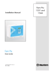
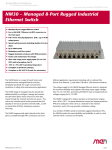
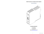
OTMC 100
Quick Start Guide
Smart Measurement Solutions®
OTMC 100 Quick Start Guide
Manual Version: OTMC100QS.ENU.2
© OMICRON Lab 2015. All rights reserved.
This user manual is a publication of OMICRON electronics GmbH.
This user manual represents the technical status at the time of printing. The product
information, specifications, and all technical data contained within this user manual are not
contractually binding. OMICRON electronics reserves the right to make changes at any time to
the technology and/or configuration without announcement. OMICRON electronics is not to be
held liable for statements and declarations given in this user manual. The user is responsible for
every application described in this user manual and its results. OMICRON electronics explicitly
exonerates itself from all liability for mistakes in this manual.
Please feel free to copy and print this manual for your needs.
Microsoft, Windows, and Internet Explorer are either registered trademarks or trademarks of
Microsoft Corporation in the United States and/or other countries. Mozilla® and Firefox® are
registered trademarks of the Mozilla Foundation. Google Chrome is a trademark of Google Inc.,
used with permission. Apple and Bonjour are registered trademarks of Apple Inc. OMICRON
Lab and Smart Measurement Solutions are registered trademarks of OMICRON electronics
GmbH.
2
OTMC 100 Quick Start Guide
Contents
1
Introduction ........................................................................................................ 4
1.1
About This Quick Start Guide .........................................................................
4
1.2
About the OTMC 100 ........................................................................................
4
1.3
General Safety Instructions ............................................................................
4
2
Device Overview ................................................................................................
6
3
Mounting ............................................................................................................
8
3.1
Safety Instructions ...........................................................................................
8
3.2
Suitable Mounting Positions ...........................................................................
8
3.3
Mounting Instructions ..................................................................................... 10
3.3.1
Mounting Instructions for Mast Mounting ........................................................... 10
4
Connecting the OTMC 100 to an Ethernet Network ....................................... 13
5
Accessing the OTMC 100 from a Computer .................................................... 15
6
5.1
System Requirements ..................................................................................... 15
5.2
Accessing the OTMC 100 Web Interface ....................................................... 15
Troubleshooting ................................................................................................ 18
6.1
7
Performing a Factory Reset (Reset to Factory Defaults) ............................. 19
Open Source Software License Information ................................................... 20
Support ............................................................................................................... 21
3
OTMC 100 Quick Start Guide
1
Introduction
1.1
About This Quick Start Guide
This OTMC 100 Quick Start Guide provides short information on how to install and access the
OTMC 100. It is intended as an aid for the user to install the OTMC 100 and take it into
operation quickly and easily. The OTMC 100 Quick Start Guide thus provides only a small
subset of information available for the OTMC 100. It cannot substitute the OTMC 100 Series
User Manual.
Therefore, also read the OTMC 100 Series User Manual which is available in PDF format on the
CD ROM delivered with the OTMC 100 in addition to this Quick Start Guide. The OTMC 100
Series User Manual provides extensive and more detailed information about the OTMC 100, its
installation and intended use, and how to configure and operate it.
1.2
About the OTMC 100
The OTMC 100 is an antenna-integrated GPS controlled time reference. It provides highprecision time to synchronize intelligent electronic devices (IEDs), computers and measurement
equipment in Ethernet (TCP/IP) based networks. The OTMC 100 series products can be used
as a PTP (Precision Time Protocol) grandmaster clock according to the IEEE 1588-2008
standard and as an NTP (Network Time Protocol) time server for NTPv4 compliant equipment
according to RFC 5905.
The OTMC 100 is designed for outdoor use in lightning protected areas. It is intended for fixed
installation on masts. For installation requirements, please refer to chapter "Mounting" on page
8 or to the OTMC 100 Series User Manual.
1.3
General Safety Instructions
Before operating the OTMC 100, carefully read the following general safety instructions:
• The OTMC 100 may only be used in a safe technical condition taking into account its defined
purpose, safety requirements and possible risks as well as the operating instructions given in
the OTMC 100 Series User Manual!
• The OTMC 100 is exclusively intended for the application areas specified in chapter
"Introduction and Designated Use" of the OTMC 100 Series User Manual. The manufacturer
or the distributors are not liable for damage resulting from unintended usage. The user alone
assumes all responsibility and risks.
• Do not open the OTMC 100! Opening the device invalidates all warranty claims!
• The OTMC 100 is an SELV device (Safety Extra Low Voltage) which is supplied with power
by Power over Ethernet (PoE according to IEEE 802.3af). It may only be connected to
Ethernet network ports or Power over Ethernet power supplies.
4
Introduction
• Always use the waterproof RJ45 Ethernet connector supplied with the OTMC 100 in order to
maintain the watertightness of the device. Do not use the OTMC 100 outdoors without a
waterproof connector inserted.
• For outdoor installation always use shielded Ethernet cable. The cable shield has to be
connected to the shield of the Ethernet connectors.
5
OTMC 100 Quick Start Guide
2
Device Overview
Membrane vent covering the pushbutton
(tightening torque: 0.6 - 0.8 Nm)
Threaded hole
1/4" BSW x 6.5 mm
for temporary mounting
on a stand
Weight: < 500 g
Degree of protection:
IP67 (for outdoor use) if the waterproof
RJ45 connector is inserted properly
Protective cap
2 threaded holes
M6 x 9 mm
for clamping block
106.2 mm
Base plate
36 mm
LED
14.5 mm
Type plate with
product name
and serial number
Waterproof RJ45 connector
acc. to IEC 61076-3-106,
variant 4
Ø 115.5 mm
The OTMC 100 does not provide an ON/OFF switch! The device automatically powers up after
supply voltage is provided via Ethernet (PoE).
The LED indicates the device status:
6
LED continuously off
The OTMC 100 is not supplied with power via the RJ45 Ethernet
connector (→ see Troubleshooting on page 18).
LED lights red
Device reboot is in progress.
LED flashes red
Software update is in progress.
ATTENTION: Do not disconnect the OTMC 100 from its PoE source
(Ethernet network) during a software update!
LED lights orange
Intermediate state when entering the recovery mode manually or
when initiating a factory reset.
LED flashes green
The OTMC 100 is in the recovery mode, waiting for new software. In
the recovery mode, the device provides only a rudimentary Web
Interface just allowing for the upload of a software image.
LED lights green
The OTMC 100 is ready for operation.
Device Overview
The pushbutton can be accessed after unscrewing the water-tight membrane vent (tightening
torque: 0.6 to 0.8 Nm).
Membrane vent
detached
Pushbutton
Pushbutton
LED
The pushbutton can be used to:
• Initiate a factory reset to reset the device configuration to the factory defaults (→ see
Troubleshooting on page 18).
• Initiate a device reboot (→ see "Performing a Reboot of the OTMC 100" in the OTMC 100
Series User Manual).
• Enter the recovery mode in order to upload software to the device, for example, if a software
update process failed (→ see "Entering the Recovery Mode Manually (and Uploading New
Software to the OTMC 100)" in the OTMC 100 Series User Manual).
7
OTMC 100 Quick Start Guide
3
Mounting
3.1
Safety Instructions
A position with good view to the sky will usually be located in a lightning endangered zone
outside of a building. The OTMC 100 must not be exposed to direct lightning strokes and thus
has to be protected sufficiently. Therefore, the OTMC 100 has to be mounted in an area
protected by a lightning protection system according to the relevant standards and regulations.
The user is responsible for sufficient lightning protection of the device and the observance of all
lightning protection regulations relevant for the site of installation.
Always use the waterproof RJ45 Ethernet connector supplied with the OTMC 100 in order to
maintain the watertightness of the device. Do not use the OTMC 100 outdoors without a
waterproof connector inserted.
CAUTION
Risk of injury or damage due to high voltages caused by lightning stroke.
• The installation of the OTMC 100 and the implementation of lightning
protection measures have to be performed by accordingly qualified experts.
• Always observe all relevant lightning protection regulations.
• The local lightning protection regulations and the protection concept of the
building and the electrical installation may require a suitable surge protection
device for the Ethernet network cable leading into the building.
• For outdoor installation always use shielded Ethernet cable. The cable shield
has to be connected to the shield of the Ethernet connectors.
3.2
Suitable Mounting Positions
The OTMC 100 receives the time information from the satellites of the GPS system. However,
GPS reception generally requires a plain line of sight between the antenna and the satellites.
For proper function, the OTMC 100 requires signal reception from at least 4 GPS satellites. The
more satellites it can receive, the more reliable the time information the OTMC 100 can deliver.
The OTMC 100 should generally be mounted outdoors at a location that provides free view in a
range of 180° vertically to the sky and 360° horizontally around the device. The view to the sky
must not be blocked by any objects. This is usually given when mounting the OTMC 100 on a
roof or a sufficiently high mast. Refer to the figure below.
You should furthermore consider that GPS signals may be reflected by large buildings and
structures around the OTMC 100, which may deteriorate the timing accuracy of the OTMC 100.
8
Mounting
Always mount the OTMC 100 in an upright position with the protective cap to the top, as shown
in the figure below. The RJ45 connector on the base plate of the OTMC 100 must point
vertically downwards. Do not mount the OTMC 100 inclined to any side or with the base plate to
the top!
Mount the OTMC 100 in an upright position
with the protective cap to the top only!
BEST position.
Recommended!
1
Possible position.
2
Possible if no alternative position is
available. Not recommended!
3
BAD position.
Will not work properly!
4
Always observe all relevant
lightning protection regulations!
Provide a suitable surge
protection device to the Ethernet
cable leading into the building!
Use shielded Ethernet cable only!
9
OTMC 100 Quick Start Guide
3.3
Mounting Instructions
There are two possible ways for mounting the OTMC 100.
Mast mounting using the delivered mast
mounting kit (see Mounting Instructions for Mast
Mounting on page 10).
3.3.1
Temporary mounting using the 1/4"
BSW (British Standard Whitworth)
thread for mounting on a stand, for
example.
Mounting Instructions for Mast Mounting
The mounting kit delivered with the OTMC 100 contains the following parts:
• 1 mast clamp consisting of 2 clamping jaws and 4 fastening screws M6 x 110 with lock
washers
• 2 clamping blocks and 4 fastening screws M6 x 16 with lock washers
• 1 connection pipe 20 x 300 mm
Proceed as follows:
Assemble the mast clamp and attach it to the mast
as shown in the figure.
The mast clamp is suitable for mast diameters of 25
to 70 mm.
Use a tightening torque of 5 Nm for the fastening
screws of the clamping block (1). The tightening
torque for the fastening screws of the mast clamp (2)
depends on the material and diameter of the mast.
10
1
2
Mounting
Attach the clamping block (3) to the base plate of the
OTMC 100 as shown in the figure.
Use a tightening torque of 5 Nm for the fastening
screws.
Exclusively use the two M6 x 16 screws delivered
with the mast mounting kit! Do not use longer
screws! The threaded holes in the base plate are
only 9 mm deep.
Insert the connecting pipe (4) to the clamping blocks
on the mast clamp and the OTMC 100 as shown in
the figure.
3
4
5
Align the OTMC 100 in an upright position as shown
in the figure and tighten both clamping screws (5) of
the clamping blocks evenly with a tightening torque
of 5 Nm.
Assemble the delivered waterproof RJ45 connector
to the Ethernet cable according to the accompanying
assembly instructions and insert it to the RJ45
connector on the base plate of the OTMC 100. Use
suitable cable ties to fasten the Ethernet network
cable to the connecting pipe and the mast.
11
OTMC 100 Quick Start Guide
Always use the waterproof RJ45 Ethernet
connector supplied with the OTMC 100 in
order to maintain the watertightness of the
device. Do not use the OTMC 100 outdoors
without a waterproof connector inserted.
The clamping blocks provide holes for
horizontal and vertical mounting of the
connecting pipe. Therefore, it is also
possible to mount the OTMC 100 on the
top of a vertically mounted connecting pipe,
as shown in the figure on the right.
12
Connecting the OTMC 100 to an Ethernet Network
4
Connecting the OTMC 100 to an Ethernet Network
Note regarding network switches:
The precise synchronization of clocks via Ethernet networks requires that the
propagation delay times for data packets is constant on the entire network. Network
switches that do not provide transparent clock functionality may introduce jitter and
thus influence the propagation delay. Therefore, the OTMC 100 will only be able to
provide highly accurate time synchronization in networks that that are equipped with
network switches providing transparent clock functionality as specified in IEEE
1588-2008 or that do not have a network switch at all.
Do not connect conventional RJ45 connectors that are equipped with a locking tab to
the OTMC 100! The locking tab of such connectors cannot be accessed directly
anymore after inserting the plug to the OTMC 100. In this case, a small screwdriver
must be used to carefully unlock the RJ45 connector in the socket. Use the
waterproof RJ45 connector supplied with the OTMC 100 instead or, when using a
cable with a conventional RJ45 connector (for test purposes only!), break off the
locking tab at the RJ45 connector before inserting it to the OTMC 100.
The OTMC 100 is supplied with power by Power over Ethernet (PoE) according to
IEEE 802.3af. If the network port the OTMC 100 is connected to does not provide PoE, a PoE
injector has to be used as shown in the figure below.
The OTMC 100 supports Ethernet cable lengths of up to 100 m without the need of repeaters.
The OTMC 100 automatically powers up after inserting the RJ45 plug and providing supply
voltage to the OTMC 100. After the device is supplied with voltage, the LED first lights up red for
approx. 15 s during the boot process and then changes to green to indicate operational
readiness.
The OTMC 100 is a class 1 powered device (PD) as defined in IEEE 802.3af (power
consumption < 3.84 W). The network port the OTMC 100 is connected to must be able
to supply a class 1 powered device.
CAUTION
Risk of injury or damage due to high voltages caused by lightning stroke.
The local lightning protection regulations and the protection concept of the
building and the electrical installation may require a suitable surge protection
device for the Ethernet network cable leading into the building.
13
OTMC 100 Quick Start Guide
The following figure shows the general arrangement of the OTMC 100, the surge protection
device and the PoE injector (if necessary).
Surge protection device
Surge protection device
PoE injector
Mains
Ethernet network port
not providing PoE
Ethernet network port
providing PoE
The following figure shows a typical network with one OTMC 100, a network switch providing
transparent clock functionality, and several PTP slaves.
Network switch
(transparent clock)
PTP slave
14
PTP slave
PTP slave
PTP slave
Accessing the OTMC 100 from a Computer
5
Accessing the OTMC 100 from a Computer
The OTMC 100 automatically powers up after supply voltage is provided via Ethernet (PoE).
The LED lights up green when the device is ready for operation.
After that, a network IP address is assigned automatically in order to connect the device to the
network. If a DHCP server is available in the network, the IP address is assigned by the DHCP
server. If not, the OTMC 100 automatically selects and assigns a link-local IPv4 and IPv6
address by itself.
5.1
System Requirements
Your computer must fulfill the following requirements to access the OTMC 100 Web Interface:
• Network port configured for operation in the network the OTMC 100 is connected to.
• OMICRON Device Browser installed.
• Web browser installed (Microsoft Internet Explorer 9 or higher, Mozilla Firefox, or Google
Chrome).
If you are accessing the OTMC 100 from a Mac or Linux operating system supporting
zeroconf, you can access the web interface of the OTMC 100 by entering
http://<hostname>.local to the address bar of your web browser. The default
hostname is a combination of the device type and the serial number separated by
dash, for example: OTMC100p-AA001A. The serial number is available on the type
plate on the bottom side of the OTMC 100 (labeled "SerNo").
5.2
Accessing the OTMC 100 Web Interface
Proceed as follows to access the OTMC 100 Web Interface:
1. Connect your computer to the network.
2. If necessary, install the OMICRON Device Browser on your computer:
• Exit all other major programs running on your computer.
• Insert the CD ROM into your computer’s CD ROM drive and click Install Device Browser
on the start page. Should the start page not be displayed automatically a few seconds
after the CD has been inserted into the CD ROM drive, change to the Windows Explorer
and double-click autorun.exe on the CD ROM.
• Follow the instructions displayed on the screen to install the OMICRON Device Browser
software.
3. Launch the OMICRON Device Browser.
15
OTMC 100 Quick Start Guide
4. The Device Browser will automatically find and display the OTMC 100.
If the IP address configurations of the OTMC 100 and the computer are not compatible, the
respective status is displayed in the Status column. In this case, right-click the OTMC 100
serial number and select Set Network Configuration to assign a suitable IP address to the
OTMC 100.
5. Right-click the OTMC 100 serial number and select Open Web Interface from the context
menu.
16
Accessing the OTMC 100 from a Computer
6. The start page of the OTMC 100 Web Interface is displayed in the web browser.
7. Refer to the OTMC 100 Series User Manual for information on how to configure and operate
the OTMC 100. Section "Next Steps to Set Up the OTMC 100" in the OTMC 100 Series User
Manual provides an overview of steps required to configure the OTMC 100 according to your
needs.
Clicking Manual in the top right corner of the Web Interface displays the OTMC 100
Series User Manual in PDF format. Clicking Help displays the start page of the help
system for the Web Interface.
17
OTMC 100 Quick Start Guide
6
Troubleshooting
The OTMC 100 automatically powers up after inserting the RJ45 plug and providing supply
voltage to the OTMC 100. After the device is supplied with voltage, the LED first lights up red for
approx. 15 s during the boot process and then changes to green to indicate operational
readiness. In case of operational problems with the OTMC 100, please use the following table
to solve the problem.
The OTMC 100 Series User Manual contains detailed descriptions of the operating procedures
possible for the OTMC 100 directly on the device and via its Web Interface.
Membrane vent
detached
Pushbutton
Pushbutton
LED
Problem / LED Indication Description / Possible Cause / Remedy
LED continuously off
The OTMC 100 is not supplied with power via the RJ45 Ethernet
connector due to one of the following reasons:
• The network port the OTMC 100 is connected to does not
provide Power over Ethernet (PoE) according to IEEE 802.3af
or is not able to supply a class 1 powered device. Use a
suitable network port or use a PoE injector (→ see
Connecting the OTMC 100 to an Ethernet
Network on page 13).
...
18
Troubleshooting
LED continuously off
(cont.)
• The waterproof RJ45 Ethernet connector used to connect the
OTMC 100 is defective or not mounted properly. Check the
pin assignment and the connection of the RJ45 connector
and mount it properly, if necessary. The Ethernet patch cable
delivered with the OTMC 100 can be used for test purposes
(break off the locking tab of the cable's Ethernet connector
before inserting the cable to the OTMC 100!) (→ see
Connecting the OTMC 100 to an Ethernet
Network on page 13).
LED flashes green
The OTMC 100 is in the recovery mode, waiting for new
software. Refer to chapter "Operating the OTMC 100" of the
OTMC 100 Series User Manual.
The password dialog is
displayed when accessing
the Web Interface of the
OTMC 100. You do not
know the password.
Perform a factory reset on the OTMC 100 (→ see "Performing a
Factory Reset (Reset to Factory Defaults)" below).
6.1
Performing a factory reset disables password protection and
resets the currently defined password to the factory default
password timeserver.
Performing a Factory Reset (Reset to Factory Defaults)
The pushbutton can be accessed after unscrewing the water-tight membrane vent. Use a
pointed tool such as a ball-pen to press the pushbutton (see figure on page 18).
WARNING
Do not forget to reinsert the membrane vent in order to restore watertightness.
Tighten the membrane vent with a tightening torque of 0.6 to 0.8 Nm.
1. Press the pushbutton and keep it pressed.
2. The LED goes off.
3. After approx. 5 s, the LED lights up orange. Keep the button pressed and wait until the LED
lights up red.
4. Release the pushbutton.
5. After approx. 15 s the LED changes to green to indicate operational readiness.
The device now has the factory default configuration settings. Password protection is disabled
and the password is reset to the factory default password timeserver.
19
OTMC 100 Quick Start Guide
7
Open Source Software License Information
Parts of the OTMC 100 software are under OMICRON license, other parts are under open
source software licenses. For the complete licensing information on the open source software,
please launch the OTMC 100 Web Interface and click the License Information hyperlink in the
bottom right corner.
The open source code is available on the Internet under www.omicron.at/opensource.
20
Support
Support
When you are working with our products we want to provide you with the greatest possible
benefits. If you need any support, we are here to assist you!
24/7 Technical Support - Get Support
www.omicron-lab.com/support
Offering our customers outstanding support is one of our top priorities. At our technical support
hotline, you can reach well-educated technicians for all of your questions. Around the clock –
competent and free of charge.
Make use of our 24/7 international technical support hotline:
Americas: +1 713 830-4660 or +1 800-OMICRON
Asia-Pacific: +852 3767 5500
Europe / Middle East / Africa: +43 59495 1000
Additionally, you can find the OMICRON Lab Service Center or OMICRON Lab Sales Partner
closest to you at www.omicron-lab.com.
OMICRON electronics GmbH, Oberes Ried 1, 6833 Klaus, Austria. +43 59495.
21
Version 2.0
[email protected]
www.omicron-lab.com
© OMICRON Lab, 2015
OTMC 100 Quick Start Guide engl.
All rights reserved.