1
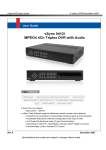
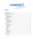
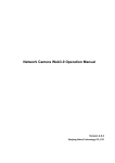
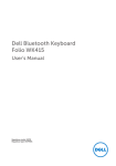
LHK110EK/LHK110EE 2.4GHz Smart Home Security System with 7-inch Touch Control Panel Instruction Guide * This product belongs to part of a security system that monitors/operates 24 hours nonstop. ** The contents in this manual are subject to modifications without notice. Safety Notice 1.Do not drop, puncture or disassemble the panel or camera; otherwise the warranty will be voided. 2.Avoid all contact with water, and dry hands before using. 3.Never tug on the power cords. Use the plug to unplug it from the wall outlet. 4.Do not expose the panel or accessory camera to high temperature or leave it in direct sunlight. Doing so may damage the device or cause the device to malfunction. 5.Use the device with care. Avoid harsh impact on the device. 6.For your own safety, avoid using the accessory camera or power off the camera when there is a storm or lightning. 7.The panel is for indoor use. Do not expose the panel to outdoor harsh weather. 8.Use only the accessories and power adapters supplied by the manufacturer. 9.To meet the regulations pertaining to parental responsibility, keep the device out of the reach of infants. FCC/CE Warning This equipment has been tested and found to comply with limits for a Class B digital device, pursuant to Part 15 of the FCC rules and ETSI (EN) 300 440. These limits are designed to provide reasonable protection against harmful interference in residential installations. This equipment generates, uses, and can radiate radio frequency energy, and if not installed and used in accordance with the instructions, may cause harmful interference to radio communications. However, there is no guarantee that interference will not occur in a particular installation. If this equipment does cause interference to radio or television equipment reception, which can be determined by turning the equipment off and on, the user is encouraged to try to correct the interference by one or more of the following measures: - Reorient or relocate the receiving antenna. - Move the equipment away from the receiver. - Plug the equipment into an outlet on a circuit different from that to which the receiver is connected. - Consult the dealer or an experienced radio/television technician for additional suggestions. You are cautioned that any change or modifications to the equipment not expressly approved by the party responsible for compliance could void your authority to operate such equipment. Disposal If the camera system no longer functions or can no longer be repaired, it must be disposed of according to the valid statutory regulations. Disposal of spent batteries/accumulators: You are required by law (Battery Ordinance) to return all spent batteries and accumulators. Disposing of spent batteries/accumulators with common household waste is prohibited! Batteries/accumulators that contain hazardous substances are marked with the symbols on the side. These symbols indicate that it is prohibited to dispose of these batteries/accumulators in the household waste. The abbreviations for the respective heavy metals are Cd = cadmium, Hg = mercury, Pb = lead. You can return spent batteries/accumulators that can no longer be charged to the designated collection points in your community, outlets or wherever batteries or accumulators are sold. Following these instructions will allow you to fulfill the legal requirements and contribute to the protection of our environment! -2- Lithium-Polymer Battery Warning 1.This equipment contains a rechargeable lithium-polymer battery. 2.Do not charge the battery in temperatures below 0° C (32° F) or higher than 45° C (113° F). 3.Do not open or disassemble the battery. 4.The rechargeable batteries contained in this equipment may explode if put in or near a fire. 5.Do not short-circuit the battery. 6.Do not charge the rechargeable battery pack used in this equipment with any charger other than the one designed to charge this battery pack as specified in the owner’s manual. Using another charger may damage the battery pack or cause the battery pack to explode. CAUTION! Rechargeable Batteries Must Be Recycled or Disposed of Properly. Device ID System “Device ID” is provided on a label located on the back of the unit. The “Device ID” is needed for remote viewing and control. For security purpose, it is recommenced for user to copy the “Device ID” information to the user manual (in the blank below), followed by removing the label containing the information of “Device ID”. Please store this manual in a safe place to protect the device ID information for future reference. Device ID: Local Regulations Always use discretion when installing CCTV surveillance equipment especially when there is perceived policy. Enquire regarding local regulations applicable to the lawful installation of video recording/surveillance. Third party consent may be required. Requirements for Remote View Supported Device - iPhone / iPad with iOS 5.0 or later - Android smartphone / tablet V4.0 or later Note: 1) Not suitable for Windows or Blackberry Smartphones 2) Up to 6 remote connections are allowed at the same time Recommended internet upload speed 512Kbps upload speed (or bandwidth) to achieve up to an average of 2FPS viewing speed. 2Mbps or more is recommended to achieve better frame rates on a smartphone’s live view. Average viewing speed will depend on other restrictions by your ISP (internet service providers). -3- Table of Contents Introduction5 Package Contents 6 Product Overview 6 Getting Started 7 Screen Display and Indicators 9 Operations Layer Diagram 11 Operation - Cameras 12 Replay 12 Record All 13 Schedule 13 Operation - Lights 14 Controlling the Lights 14 Operation - Alarms 15 Setting Alarm Mode 15 Viewing Logs 16 Setting - Cameras Setting - Lighting Fixtures Setting - Alarms Setting - Network 20 Security Code 20 Network Information 20 Email Alert 20 Setting - Advanced Options 21 Using APP on a Mobile Device 23 Downloading the APP 23 Launching the APP 23 Adding a New Panel 23 Registration23 Main Functions Display 24 Live Camera View 24 26 Setting Lighting Fixtures 27 System Info 28 Specifications 29 FAQ30 List of Compatible Devices 30 Appendix A Arm Mode Flowchart 31 Appendix B Silent Arm Mode Flowchart 31 Appendix C Panic&Tamper Mode Flowchart32 Appendix D Disarm Mode Flowchart 32 17 18 19 20 Internet Setup Setting Alarm Mode and Viewing Eventlog Playback25 -4- Introduction The touch control panel is designed to be the security center of your home. The system consists of a touch screen control for system operation, cameras that monitor the surroundings of your residence, various wireless sensors that provide perimeter and interior intruder protection, and lighting fixtures. The system provides protection at home in three areas as depicted below: OUTDOOR ZONE Front door INDOOR ZONE Window W PERSONAL ZONE Device classification: Outdoor Zone: Lighting Cam Window Indoor Zone : Motion sensor, Door/Window contact detector Personal Zone: Keyfob Panic button Back door After setting the panel to be connected with cameras and alarms, you can arm or disarm the system and view live camera images on this panel. The panel can also link up with smart plugs and lighting fixtures for wireless control of the lighting of your residence. When a trigger event occurs, the system emits an alarm sound and can also inform the user via email alert or smart phone APP notification. Lighting fixtures may also be configured to light up to attract attention. Video images from the cameras are simultaneously streamed and recorded in the touch panel’s memory card for 2 minutes and can be played back for evidence. Through the Smartphone APP users may view live video of the camera, set the system to Arm/ Disarm, turn on/off lighting fixtures, activate recording at will and playback recorded video files. The followings are some features of the panel: • Can connect up to 4 wireless cameras and record live images by A/V signal streaming • Supports up to 8 alarm devices connection • Supports up to 8 lighting fixtures/plugs connection and up to 5 pieces of lamps can be configured to light up when alarm is triggered. • Wireless connection and control of cameras/alarms/lighting fixtures • Supports up to 32GB micro SD card (4GB card included) • Battery included (can be recharged and powered using AC adapter) • Built-in speaker -5- Package Contents • • • • • • • • 2.4GHz 7” Touch Control Panel x1 2.4GHz Lighting Camera x1 Wire Free PIR Motion Sensor x1 Wire Free Magnetic Contact x1 Wire Free Remote Control x1 Plug Through Receiver x1 4GB micro SD card x 1 Instruction Guide x1 Product Overview Power Button* Antenna Antenna Micro SD Card Slot Reset Stand LCD Touch Screen DC Power in Network Cable Connection * To power on/off the panel, press and hold down the power button for 3 seconds. After the panel is powered on, pressing the button shortly can put the unit into sleep mode. To awake the panel from sleep status, press the button once shortly. The stand comes with the panel as a support when you need to place the panel on a flat surface (such as on a table). To set up the stand, follow the steps below: 1.Align the 4 hooks of the stand with the grooves on the back of the panel. 2.Place the hooks into the grooves and then slide the stand upward. 3.When the stand clicks into the housing, the setup is complete. -6- Getting Started Unpack the kit contents and follow the steps below to set up your panel: 1. Connect the AC adapter’s connector to the panel and the adapter plug to a wall outlet. 2. Connect the RJ45 connector to the panel and the other end of the network cable to a “LAN” port of your router. The router should have “DHCP” function enabled. 3. Power on the panel by pressing and holding the power button of the panel for about 3 seconds. Follow the on-screen instructions to complete the screen calibration. 4. Insert a micro SD card (4GB card included) into the card slot. You can use your own micro SD card (max. 32GB). Format the card by tapping “Setting” “Advance” “Format Storage”. 5. After the panel is powered on and connected to the network, the panel should have internet connection within 2 minutes. The network connection icon ( ) should appear. The recommended network setting is “DHCP” which is also the factory default. If you need to configure the network settings manually, tap on “Setting” “Network” “Internet Setup” “Static IP”. -7- * 6. Pairing with the accessory lighting camera: 1) Tap on the “Setting” button on the function bar to enter the camera setting screen. 2) Select the “Light Cam” icon on the left side and highlight an available slot on the right side of the screen. Then tap on the “Pair” button. 3) Press the PAIR/ Button on the camera to do ID code learning with the panel. 4) Once the pairing is complete, the panel is able to display live camera images on the screen. Refer to page 17 for detailed camera settings. * 7. Adding the accessory alarm devices: 1) Tap on “Setting” “Alarm“ to enter the alarm setting screen. 2) There should be one PIR detector, one magnetic contact detector, and one remote control in your package. These devices should do the code learning one at a time. 3) Select the “PIR” icon on the left side and highlight an available slot on the right side of the screen. Then tap on the “Add” button. 4) Press the Learning Button (or Tamper Switch) on the PIR detector to do ID code learning with the panel. 5) Once the learning is complete, repeat step 3 and 4 to set up the contact detector and the remote control. Ensure to select a proper icon that corresponds with the to-be-added device. Refer to page 19 for detailed alarm devices settings. * 8. Adding the accessory wireless on/off plug: 1) Tap on “Setting” “Light“ to enter the lighting fixture setting screen. 2) Press the Learning Button on the wireless plug to enter code learning mode. 3) Select the “On/Off Plug” icon on the left side and highlight an available slot on the right side of the screen. Then tap on the “Add” button. 4) Once the learning is complete, the panel is able to control the on/off plug wirelessly. Refer to page 18 for detailed lighting fixtures settings. 9. Install the panel and accessory devices to appropriate locations. Note the accessory devices should be located within the RF transmission range of the panel. 10. The default system security code is “123456”. You should change the security code immediately to fortify protection. Tap on “Setting” “Network” “Security Code” to change the code. Ensure to jot down your new code and store the password card in a safe place. 11. For security purpose, you are recommended to set up the email alert contact and APP connection for push notifications. Tap on “Setting” “Network” “Email Alert” and use “System Default” or “User Settings” item to set up the email alert contact. For APP setup, refer to page 23 for detailed instructions. Note: Step 6, 7, and/or 8 can be skipped if the accessory devices are pre-learned with the control panel before shipping. Devices that are already paired with the panel will have a “Prelearned” sticker on each unit’s body, so you are able to identify which devices can work with the panel right away. -8- Screen Display and Indicators Press and hold the power button for 3 seconds to power on the panel and enter the main display. Normal view: : Battery power indicator : Micro SD card capacity indicator. The used percentage of storage is displayed. : Network status indicator. When the panel is connected to Local Area Network (LAN), the icon will appear. When the panel is linked and open to the Internet, the icon will switch to , which is also the only condition that someone in a remote location can access the system via “LuxHome Guard” - the smartphone APP. Note that whenever someone is operating the panel, the icon will switch to and any attempt of remote access will be denied. This is to ensure the top priority of domestic operation. The panel will switch to status after a short period of idling (provided the panel is connected to Internet). : Quad view & trigger indicator. Tap to enter cameras quad view. White icon means no trigger. If a trigger has occurred, a red icon is happening, the red icon cameras to start recording. will display. If a trigger event will flash, and you can tap the icon to enable all Note: When the panel is in camera live view, camera scanning, or video replaying, the connected camera(s) will not automatically record videos upon triggered event. However, within 10 seconds of trigger, you can tap on the flashing icon to start recording. : Tap to set Arm/Disarm/Silent Arm -9- : Tap to go back to previous display : Tap to go back to home display Message bar Main operation area Group operation buttons Camera view: Active camera/Signal strength indicator : Tap to digitally magnify the screen : Toggle recording on/off : Tap to adjust screen brightness : Tap to adjust sound volume Tap the MENU button to return to camera operation page Note: In the camera live view, the lighting camera will turn on its light for better viewing if the environment is too dark. - 10 - SETTINGS LAYER OPERATION LAYER STANDBY Replay Pair page 17 Cam page 12 Schedule Record All Cam Standby Power page 18 Pair/Unpair Light page 14 Light Log - 11 - page 19 Pair/Unpair Alarm page 15 Alarm Time Zone Email Alert page 21 Factory Default System Format Language Screen Lock Network Info page 20 Standby Mode Power Saving Advance Network Setup Security Code Network Settings The following chart is an illustration for all operation displays of the panel. Use this chart as a reference for functions operation. Operations Layer Diagram Operation - Cameras In this display you can view the camera images in several ways: Quad view: Tap on the “Quad” button to switch to quadruple cameras view. All four cameras live images will display on the screen. You can then tap on any of the camera view to switch to fullscreen display. Tapping on the screen again will switch back to the quad view. Scan view: Tap on the “Scan” button to scan between all available cameras. Cam 1-4: Tap on the intended camera button to view its live image. On the right side of the screen you can find more buttons for 1) Replaying recorded videos; 2) Recording with all cameras; 3) Setting up recording schedules: Replay 1.Tap on the “Replay” button and the following screen will display. 2.Tap on the intended camera or the “Cam All” button, and the dates containing recorded files are marked in green color. 3.Tap on one of the marked dates and a list of available recordings will show up. Then select the intended file to replay. 4.On the bottom of the replay screen is a control bar for you to navigate the playing. You can also tap on the screen to bring up a time bar and use the time bar to jump to the section that you want to view. To return to previous screen, tap on the button. Note: When only one camera is connected, the resolution of video is 480x272 and sound is recorded. However, when 2 or more cameras are connected, the recorded video will become QVGA (320x240) with no sound. - 12 - Record All Tap on the “Record All” button and all cameras will start recording immediately. The recording will last for 2 minutes. Schedule Up to 5 scheduled recording sessions are available in a single day. You are limited to the size of the micro SD card for how long a total of recording time you will have. 1.Tap on the “Schedule” button and the following screen will display. 2.Select on the left side bar the number of the schedule. You can configure up to 5 schedules. 3.Select the camera that you want to set up. Tap on the week day that you would like the camera to record. Multiple cameras can be configured. Tap on the “Save” button to save the setting. 4.If you want to specify time frame, tap the “Time” button to further configure the time for recording. The default time setting is from 12:00am to 11:59pm. Make sure to tap the “Save” button to save the setting before exiting the setup screen. 5.Repeat the procedures with other schedules if you want to set up multiple recording time tables. Ensure to save the schedules for the settings to take effect. Note: If the recording is longer than 15 minutes, it will be divided into clips (with each clip lasting for 15 minutes maximum). The actual available recording time is limited by the capacity of the memory card. - 13 - Operation - Lights This display is for controlling all lighting fixtures connected in the system. Fixture status: : The lighting fixture is off. : The lighting fixture is on. Controlling the Lights 1.Tap on the intended lighting fixture to turn it on or off. 2.If the highlighted fixture is dimmable, a button will appear on the right side of the screen. To adjust the brightness of the dimmable fixture or light bulb, tap on the button once and the brightness will start to cycle. When the brightness is right for you, tap on the button again to stop the cycle. Note: When a dimmable light is turned on, it will automatically restore the last brightness state. - 14 - Operation - Alarms This display is for controlling all alarm devices connected in the system. Setting Alarm Mode The panel provides 3 alarm modes for you to choose from: • Arm: This is the most comprehensive protection mode (equals Full Arm). When the system is triggered, a full alarm condition will be initiated. It is suitable for guarding your home when your whole family are away. • Silent Arm: This alarm mode will not activate sirens when triggered. • Disarm: Only the lighting camera will record videos when it is triggered. Tap on the Arm/Disarm/Silent Arm button to set the security mode of all alarm devices. The switch of status would take a few seconds to complete. The three security modes and what actions will be taken when system is triggered are described as following: Mode Arm (= Full Arm) Triggered Device Actions when Triggered PIR or Contact Detector 1) All cameras will start recording. 2) The “bound” lighting fixtures will turn on for 3 minutes. 3) The siren will sound for 3 minutes. 4) The email alert and APP notice will be sent. 5) Writes to “Event Log” of the panel. Lighting Camera Same as above except that only the triggered camera will start recording. Doorbell 1) The panel and chime sounder will chime for 4 seconds. 2) The email alert and APP notice will be sent. 3) Writes to “Event Log” of the panel. - 15 - Silent Arm Disarm PIR or Contact Detector 1) All cameras will start recording. 2) The “bound” lighting fixtures will turn on for 3 minutes. 3) The siren will NOT sound. 4) The email alert and APP notice will be sent. 5) Writes to “Event Log” of the panel. Lighting Camera Same as above except that only the triggered camera will start recording. Doorbell 1) The panel and chime sounder will chime for 4 seconds. 2) The email alert and APP notice will be sent. 3) Writes to “Event Log” of the panel. PIR or Contact Detector No action will be taken. Lighting Camera The triggered camera will start recording. Doorbell 1) The panel and chime sounder will chime for 4 seconds. 2) The email alert and APP notice will be sent. In addition to the above-mentioned three modes, there are other conditions, such as panic alert initiated by the user, can also trigger alarms: Mode Triggered Device Actions when Triggered Intruder Panic Remote control / APP 1) All cameras will start recording. 2) The “bound” lighting fixtures will turn on for 3 minutes. 3) The siren will sound for 3 minutes. 4) The email alert and APP notice will be sent. 5) Writes to “Event Log” of the panel. Medical Panic Panic button Same as above. Tamper Alert Sensor tamper Same as above. Viewing Logs 1.To view the log of alarm events, tap on the “Log” button and a list of events will show up. If the event comes with a video recording, a “Play” icon ( ) will appear. You can tap on the icon to replay the recording. 2.On the bottom of the replay screen is a control bar for you to navigate the playing. You can also tap on the screen to bring up a time bar and use the time bar to jump to the section that you want to view. To return to previous screen, tap on the button. - 16 - Setting - Cameras Note: 1) Set the system to Disarm mode before pairing/unpairing. 2) When only one camera is connected, the resolution of video is 480x272 and sound is recorded. However, when 2 or more cameras are connected, the recorded video will become QVGA (320x240) with no sound. This display is for pairing and setting cameras. The panel can connect with up to 4 cameras. There are two types of cameras to select from: Light Cam: If a camera is paired with this option, it will record videos when the system or the camera itself is triggered*. Recommended for cameras guarding your properties. * During camera live view, scanning, or video replaying, the cameras will not automatically record videos upon trigger. Tap on the flashing icon to start recording. IR Cam: If a camera is paired with this option, the camera’s own PIR is disabled so it will not record video by itself. However, it will record video upon other triggered event (sensors, panic button, tamper...etc.). Recommended for cameras on the perimeter of properties (e.g. facing the main road). Pairing: 1.Select the type of the camera (a Light Cam or an IR Cam) and an available slot for the camera. If you want to replace an old camera, you need to “unpair” the old camera first to free up the slot. 2.Tap on the “Pair” button to start pairing. The screen will display the pairing indicator. 3.Press the PAIR/ Button on the camera to emit ID code for pairing. 4.If the pairing is successful, the camera’s icon will occupy the slot assigned. 5.If the camera’s icon does not appear within 12 seconds, the pairing is not successful. Repeat steps 1-3 to retry pairing with the camera. Unpairing: 1.Select the icon of the paired camera (a lighting camera or an IR camera) that you wish to unpair. 2.On the panel’s screen, tap on the “Unpair” button to start unpairing. 3.Unpairing message will display on the screen. If the unpairing is successful, the icon on the panel will be restored to default . 4.If the icon does not change within 12 seconds, the unpairing is not successful. Repeat step 2 and 3 to retry. - 17 - Setting - Lighting Fixtures Note: Set the system to Disarm mode before adding/removing lighting fixtures. This display is for learning and setting lighting fixtures. The panel can connect with up to 8 lighting fixtures. Adding: 1.Select the type of the light. There are 6 types of lighting items for selection: 1) On/Off Plug: A plug that provides only on/off operation. 2) Dimmer Plug: A plug that provides on/off operation and dimmer function. 3) On/Off Outlet: A power outlet that provides only on/off operation. 4) Dimmer Outlet: A power outlet that provides on/off operation and dimmer function. 5) Lamp Holder: A fixture that secures and controls on/off status of a light bulb. 6) RF Lighting fixture: A lighting fixture with wireless function. 2.Select an available slot for the lighting fixture. If you want to replace an old fixture, you need to “remove” the old fixture first to free up the slot. 3.Press the Learning Button on the lighting fixture to enter code learning mode. 4.On the panel’s screen, tap on the “Add” button to start code learning. 5.If the lighting fixture learns the ID code properly, tap “Yes” on the screen to complete the registration of the lighting fixture. 6.If the learning is successful, you are able to set up the title and location of the fixture: Type in the message bar to change the title of the fixture. Select the location of the fixture and press “OK” to complete setting. Note: The “Linked with alarm” option determines if the lighting fixture will light up when alarm devices in the system are triggered under Arm mode. Check this item if you want the fixture to be “bound” with the alarm system. Up to 5 lighting fixtures can be assigned this function. 7.The fixture’s icon will occupy the slot assigned and the learning is done. Removal: On the panel’s screen, select the icon of the to-be-removed device and tap the “Remove” button. Follow the on-screen instructions to remove the device. - 18 - Setting - Alarms Note: Set the system to Disarm mode before adding/removing alarm devices. This display is for learning and setting alarm devices. The panel can connect with up to 8 alarm devices. Adding: 1.Select the type of the alarm. There are 7 types of alarm items for selection: 1) PIR: A passive infrared occupancy detector. 2) Contact Detector: A door/window magnetic contact detector. 3) Remote Control: A remote control with intruder panic slide switch on the right side. 4) Doorbell: A doorbell. 5) Sounder: A siren that will sound loudly when a detector is triggered. 6) Panic: An alarm device for triggering emergency condition. 7) Chime: An alarm device that will emit pleasant chime sound when triggered. 2.Select an available slot for the device. If you want to replace an old device, you need to “remove” the old device first to free up the slot. 3.Tap on the “Add” button to start code learning. 4.Operate the device for code learning. Complete the registration with the alarm device. 5.If the learning is successful, you are able to set up the title and location of the device: Type in the message bar to change the title of the alarm. Select the location of the device and press “OK” to complete setting. 6.The device’s icon will occupy the slot assigned and the learning is done. Removal: On the panel’s screen, select the icon of the to-be-removed device and tap the “Remove” button. Follow the on-screen instructions to remove the device. - 19 - Setting - Network Internet Setup 1.Static IP: If you are familiar with the settings of your network or the “DHCP” setting does not work in your environment, you can select this option to set up the IP manually. The screen will display the following items for settings: Please consult with your internet service provider on how to configure the IP settings. 2.DHCP: This option allows the unit to obtain an IP address automatically without the hassle of configuration. You are recommended to adopt this option if your network environment allows. Security Code The default security is “123456”. You can change the security code in this setting. Network Information This item will display the system info (MAC address, security code...), firmware version, and network settings. Email Alert 1.System Default: Setting the default email contact. The email will be sent through the preconfigured server. 2.User Settings: User-defined settings for the email alert. Note if you use this setting then the System Default email contact will not be available. 3.Disable: No email alert will be sent when a trigger event occurs. Note: Some email programs, such as Outlook, may treat the alert emails as spam. Please check the junk box if you do not find the alert emails in the inbox. - 20 - Setting - Advanced Options This display is for setting/viewing advanced system options. The items are described as the following table: Item Description Two standby modes are available for selection: Standby Mode Menu: The screen will display menu interface when idling: Camera Picture: The screen will display live camera image when idling. You can enable/disable power saving mode here. If enabled, the monitor will shut down after staying idle for 2 minutes: Power Saving - 21 - This item allows you to configure if the screen will lock up after a period of idleness. Password setup would be required if you enable this function. The default password is “0000”. If you forget your password after change, you can use the “Factory Default” function to reset the password to “0000”. You can change the password in the settings window: Screen Lock This item allows you to set up the date/time/time zone settings. Ensure to tap on the “Save” button whenever you make a change: Time Zone Note: After setting the correct time zone and connecting the panel to Internet, the panel will correct its time settings automatically. The time sync takes place every 5 hours. Format Storage You can select to format the micro SD card with this option. Beware that all data saved in the card will be erased. Backup files first if they are valuable. Language This item allows you to change the UI languages. System Upgrade You can upgrade the system firmware with this function. To upgrade the firmware of the panel: 1. Power off the panel by pressing the power button for 3 seconds. 2. Remove the micro SD card from the panel and insert it to the card slot of your PC. 3. Download the latest firmware file from the manufacturer’s website and save the file to the micro SD card. 4. Take out the card from your PC and insert the card into the panel. 5. Power on the panel and initiate upgrade by tapping on “Setting” “Advance” “System Upgrade”. 6. The panel will detect the firmware file in the micro SD card and start the upgrade. 7. When the upgrade is complete, the panel will reboot automatically. Factory Default This item allows you to restore the settings of the panel to factory default. - 22 - Using APP on a Mobile Device For remote surveillance and control, you can download and use the “LuxHome Guard” application on your smartphone or mobile device. Note: 1) A Wi-Fi (or 3G/4G..etc.) connection is imperative for the operation of the APP. 2) The control panel allows up to 6 users to connect remotely (via APP) at the same time. Downloading the APP The APP can be found in Android or iOS version: 1.Android system: If you are using an Android system device, you can search and download the “LuxHome Guard” APP from “Google Play”. 2.iOS system: For i-device users, search and download the “LuxHome Guard” APP in the “APP Store”. Launching the APP After the APP completes downloading and installation, the APP icon screen of your device. Simply tap on the icon to launch the APP: Add new device to the list will appear on the More options such as Settings, About, and Exit Search for device Refresh the network connection The “Settings” item allows you to enable/disable push notice alert, vibration alert, and to set up the sound of alert Adding a New Panel Tap on the icon and you will be requested to enter the Device ID of the new panel. The Device ID (DID) can be found in the panel by tapping on “Setting” “Network” “Network Information”. Enter the name for the panel, DID, and password, and then tap on “Save” to complete. Inputting the correct “password” would be a must for connecting/viewing/operating remotely. - 23 - Main Functions Display After adding a new panel, the title of the device will display on the list screen. Tap on the connected device to enter the main functions display: Single tap: go to main functions display. Tap & hold: bring up options menu: View: go to main functions display. Modify: allows you to modify the Device ID. Useful when you change the control panel. Delete: delete the connected panel. Current settings Latest event notice Live Camera View On the main functions display, tap on the (Live Cam) icon to enter the real-time camera view. If the environment is too dark, the lighting camera will turn on its light for better viewing. Tap to return to the main functions display. Select a camera to view. Unavailable cameras are grayed out. Panic: If the live image reveals signs of intrusion, you can use this function to initiate a full alarm. Photo: Save current image as a picture in your mobile device. Refresh: Refresh the camera view. Record All: Tap on this icon to enable all cameras to start recording. The recording will last for about 2 minutes and then stop. The camera view will switch to horizontal display when you rotate your mobile device: - 24 - Playback The Playback function allows you to specify a period of time and view any recorded videos during that period. On the main functions display, tap on the (Playback) icon to enter the playback display. Follow the steps below to playback recorded videos on the specified date: 1 3 1. Set the period of time. 2 2. Tap on “Load” to continue. 3. Tap on the date that you want to view. The video recorded on that date will be able to play: Tap to return to the previous display. Select a camera to view. Unavailable cameras are grayed out. Refresh: Refresh the playback. Photo: Save current image as a picture in your mobile device. - 25 - Setting Alarm Mode and Viewing Eventlog Use the Alarm function and you can set up the alarm mode of your system and view the event log as well. On the main functions display, tap on the (Alarm) icon to enter the alarm function display. Icon image changes according to the Alarm mode that you set. Tap on the desired item to set the Alarm mode. For information on how each mode works, refer to page 15. Tap to return to the previous display. To View Eventlog Select a camera to view. Unavailable cameras are grayed out. 1 2 1. Tap on an event to continue. 2. Tap on the video that you want to view. Refresh: Refresh the playback. Photo: Save current image as a picture in your mobile device. Tap on the arrow icons to switch between pages. - 26 - Setting Lighting Fixtures The lighting control function allows you to control the on/off statuses of the lighting fixtures in your residence. The “dim” function is available for dimmable lighting fixtures. On the main functions display, tap on the (Light) icon to enter the lighting control display. On the screen you can see that all configured lighting fixtures are listed. To turn on or off a specific lighting fixture, tap on the / bar. To change the brightness of a dimmable lighting fixture, follow the steps below: 1 3 2 1. The icon will be available when a dimmable fixture is ON. Tap on the icon to “dim” the fixture. 3. Tap on “OK” when the desired brightness is reached. 2. Tap on “OK” to continue. - 27 - System Info The Setting function allows you to view the system info. On the main functions display, tap on the (Setting) icon to enter the system info display. The system info is displayed here. - 28 - Specifications Touch Control Panel LCD 7” Resistive Touch Panel Resolution 800 x 400 Power Jack DC5V Adapter DC5V 2A from AC100-240V Switching Adapter Storage Micro SD Card (FAT/FAT32) / Max. 32GB Rechargeable Battery Li-polymer 3.7V 2000mAh Internet Output Ethernet Port RJ45 Speaker Built-in Operating Temperature 0ºC-40ºC / 20-85% relative humidity non-condensation Panel Dimension 184.2(W) x 130.2(H) x 24.8(D) mm Video Camera RF 2.4GHz, GFSK modulation, Frequency Hopping Camera Transmitting Range 150m in open space Max. No. of Cameras 4 Cameras Image Encoding H.264 Recording Format 1 camera: H.264 / 480 x 272 / 30fps 2-4 cameras: H.264 / QVGA (320 x 240) / 30fps Recording Time Typically 2 minutes; up to 15 minutes upon continual triggers Alarm and Lighting Device RF 433.92MHz, ASK modulation Device Transmitting Range Refer to user manual for each device Max. No. of Alarm Devices Up to 8 Alarm Devices Max. No. of Plugs/Lights Up to 8 Plugs/Lighting Fixtures * Specifications are subject to change without notice. - 29 - FAQ • Q: How large is a recorded video? • A: The average size of a video is about 5MB (2 minutes, 150KB/sec.). A 4GB card can hold about 400 videos. The maximum size of a video is about 15MB (15 minutes, 150KB/sec.). A 4GB card can accommodate about 266 large video files. • Q: Which program can be used to play back the recorded MP4 videos on my PC? • A: To play the recorded MP4 videos on your PC, you can search and download free media player programs such as “VLC Media Player”, “GOMPlayer”, or “SMPlayer” from the Internet. • Q: Why can’t I access the system when using the APP on my smartphone or tablet from a remote location? • A: Someone in your house might be operating the panel at the same time. When someone is operating the panel, the Internet access is disabled temporarily to ensure priority. The panel will resume Internet connection after a period of idleness (provided the Internet cable is connected). List of Compatible Devices The following devices are designed to work with the 7-inch touch Control Panel. Take them into consideration if you are planning to expand your system: Lighting Camera Motion Sensor Contact Detector - 30 - Remote Control Smart On/Off Plug Appendix A - Arm Mode Flowchart Appendix B - Silent Arm Mode Flowchart - 31 - Appendix C - Panic&Tamper Mode Flowchart Appendix D - Disarm Mode Flowchart - 32 - Disposal and Recycling Disposal of this product is covered by the Waste Electrical or Electronic Equipment (WEEE) Directive. It should not be disposed of with other household or commercial waste. At the end of its useful life the packaging and product should be disposed of via a suitable recycling center. Please contact your local authority or the retailer from where the product was purchased for information on available facilities. Guarantee The product is guaranteed for one year from the date of purchase against faulty materials and workmanship. No liability can be accepted for any problems caused by fair wear and tear, buyer’s negligence, improper fitting or use, wilful or accidental damage, or any consequential loss or damage howsoever caused. This guarantee does not affect your statutory rights and is valid for the country or region of your purchase. If you believe the product to be faulty or in the unlikely event of the product developing a fault during the warranty period, then please contact your supplier for product assistance. Product repair or replacement will be offered for faulty products only with our prior agreement. Should you need to return a product then: 1.Contact your supplier and obtain a Return Authorisation Number. 2.Adequately package your product to prevent damage in transit and include the following a. A copy of your original invoice/receipt. b. A covering letter giving your full contact details, including email address (if applicable). c. A description of the fault or problem. LuxHome Alarm Systems Copyright © 2014. All Rights Reserved. Website: www.myluxhome.com Service Support: [email protected] A501112173R02 - 33 - 2014/06