1
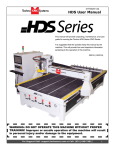
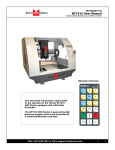
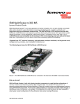
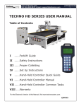
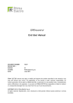
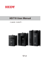
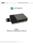
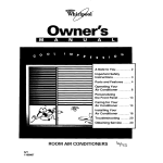
(HTT0673)
Venture User Manual
WARNING: DO NOT OPERATE THIS MACHINE WITHOUT PROPER
TRAINING! Improper or unsafe operation of the machine will
result in personal injury and/or damage to the equipment.
This manual will provide unpacking, maintenance, and user guide for running the
Techno Venture Series and Venture Plus Series CNC Routers.
It is suggested that the operator keep this manual by the machine. This will
provide the most important information pertaining to the operation of this machine.
©2015 (10/2015)
For Support Visit· support.technocnc.com or Call: (631) 648-7481
1
(HTT0673)
Venture User Manual
TABLE OF CONTENTS
I......General Installation Instructions.
1.1 Forklift guide and unpacking instructions.
.............................Page 3
1.2 Safety Instructions.
.............................Page 4
1.3 Correct Colleting..............................
Page 5
1.3.5 Toolstand
1.3.6 Spindle Warmup
.............................Page 6
1.4 Electrical and Pneumatic connections.
.............................Page 7 - 8
1.5 Vacuum Pump connections. .............................Page 9
II.....Machine Start-Up and Screen Functionality.
2.1- Start up Procedure.
.............................Page 10 - 12
2.2- Screen Callouts.
.............................Page 13 - 25
2.3- File System-Network..............................
Page 26
III... Operating Tutorials
3.1- Jogging the Machine.
3.23.33.43.53.6-
.............................Page
Learning Tool lengths.
.............................Page
Saving an Origin | Setting XYZ Zero Position.............................Page
Preparing a G-Code File.
.............................Page
Running a G-Code File.
.............................Page
Machine Origin,Working Origin, & Offsets
.............................Page
IV.....Advanced Tutorials
4.1- Using Block to Block Function.
4.2- Mem Search. 4.3- Return to Profile.
4.4- Setup Parameters.
4.5- Backing up Parameters.
V......Machine Lubrication
VI....Appendix
6.0- HSD Aggregate Tool Setup.
6.1- Fault Finding/Error Messages.
2
Warranty
.............................Page
.............................Page
.............................Page
.............................Page
27
29
31
33
35
37
-
28
30
32
34
36
38
39
40 - 43
44 - 46
.............................Page 47
.............................Page 48 - 49
.............................Page 50
.............................Page 51
For Support Visit· support.technocnc.com or Call: (631) 648-7481
(HTT0673)
Venture User Manual
www.technocnc.com
(HTT06081112)
Section I:Tel:
General
Installation Instructions
631-648-7481 • Email: [email protected]
FORKLIFT GUIDE
I. UNPACKING AND MACHINE IDENTIFICATIONS
1.1
All Techno machines are shipped assembled and secured to a wooden pallet.
Rear of Machine
Unpack all items that shipped with
your machine. Check the items
against the packing slip to be sure
nothing was left out. Notify Techno
immediately if you are missing any
pieces of your shipment.
A toolbox and other
accessories such as vacuum
hosing and leveling feet may
be packed under the machine
during shipping.
3
4
1
2
Fig. 1.1
Please note the 4 Forklift Tubes on
the front and rear of the machine.
If required, there are 4 Forklift Tubes
on the sides of the machine.
Front of Machine
II. MEASURING FORKS AND FORKLIFTING MACHINE
2.1
Forks must be centered in the front
of the machine (shown in Fig 2.1).
2.2
Measure the distance
between the forks.
(shown in Fig 2.2).
es
nch
35 i
Fig. 2.1
Fig. 2.2
SAFETY WARNING: DO NOT LIFT OR MOVE MACHINE USING GANTRY
For safety and to prevent damage to the machine
and cables, Lift Machine Using Forklift Tubes ONLY
Depending on machine size — SEE QUOTE FOR MACHINE WEIGHT
NOTE: Forklift capacity must be adequate to safely lift the machine.
It is recommended to have Fork Lift Extensions to better support the load.
2.3
Take care not to damage the
valves on the front of the machine.
Slowly move in close to the machine.
2.4
Fig. 2.4
Fig. 2.3
Forklift your machine up from the
floor and remove the wooden pallet.
For Support Visit· support.technocnc.com or Call: (631) 648-7481
3
(HTT0673)
Venture User Manual
1.2 SAFETY INFORMATION!
Read these instructions thoroughly before operating
machine. DO NOT operate machine if you are unfamiliar with
these safe operating instructions. DO NOT operate machine
without knowing where the emergency stop switch is located.
12. Stay alert at all times when operating the machine.
1.
Keep fingers, hands, and all other objects away from
machine while power is on.
2.
Disconnect power to all system components when
not in use, when changing accessories, and before
servicing.
14. Do not wear jewelry or loose-fitting clothing when
operating machine. Long hair should be protected.
3.
Do not loosen, remove, or adjust machine parts or
cables while power is on.
15. Always maintain proper balance and footing when
working around the machine.
4.
Exercise care with machine controls and around
keyboard to avoid unintentional starting.
5.
Make sure voltage supplied is appropriate to
specifications of components.
16. Maintain equipment with care. Keep cutting tools
clean and sharp. Lubricate and change accessories
when necessary. Cables and cords should be
inspected regularly. Keep controls clean and dry.
13. Always wear safety goggles.
6.
Machines must be plugged into four-pronged
grounded outlets. Do not remove the grounding
plug or connect into an ungrounded extension cord.
7.
Keep cables and cords away from heat, oil, and
sharp edges. Do not overstretch or run them under
other objects or over work surfaces.
17. Before using, check for damaged parts. An
authorized service center should perform all repairs.
Only identical or authorized replacement parts
should be used.
18. Remove any adjusting keys and wrenches before
turning machine on.
19. Do not operate the machine unattended.
8.
Use proper fixtures and clamps to secure work. Never use hands to secure work.
9.
Do not attempt to exceed limits of machine.
20. Follow all safety instructions and processing
instructions in the MSDS for the material being
processed.
10. Do not attempt to use machine for purposes other
than what is intended.
21. Use proper precautions with dust collection systems
to prevent sparks and fire hazards.
11. Use machine only in clean, well-lit areas free from
flammable liquids and excessive moisture.
22. Make sure to have proper fire extinguishing
equipment on hand at all times.
PREVENT FIRE HAZARDS by using the proper feeds, speeds, and tooling while operating your Techno machine.
For example, setting feeds and speeds too low and/or using dull tool bits creates friction at the material.
The friction generates heat which can result in a fire that can be drawn through the vacuum table or dust
collector without warning. Fire hazard from friction heating caused by dull tools is possible when cutting certain
materials, especially composite material such as wood composites, MDF and Particleboard.
© 2015
4
For Support Visit· support.technocnc.com or Call: (631) 648-7481
(HTT0673)
Venture User Manual
1.3 Correct Colleting:
Read these instructions thoroughly
BEFORE operating machine.
WARNING!
THE SPINDLE WILL BE DAMAGED
IF UNBALANCED EQUIPMENT IS USED.
AIR SUPPLY MUST BE FILTERED AND DRY.
For Support Visit· support.technocnc.com or Call: (631) 648-7481
5
(HTT0673)
Venture User Manual
1.3.5 Tool Stand Diagram - Proper Placement
Read these instructions thoroughly BEFORE operating machine.
1.3.6 — HSD Spindle Warmup
Read these instructions thoroughly BEFORE operating machine.
USE AND ADJUSTMENT
PREHEATING
HSD S.p.A. uses high-precision angular contact bearing pairs, pre-loaded and lubricated for life
with special grease for high speeds.
When the machine is switched on for the first time every day, allow the electrospindle to perform a
brief preheating cycle in order to allow the bearings to gradually attain a uniform operating
temperature, and hence to obtain a uniform expansion of the bearing races and the correct preload
and rigidity.
The following cycle is recommended, without machining operations:
50
75
100
% of the maximum rated speed for 2 minutes.
% of the maximum rated speed for 2 minutes.
% of the maximum rated speed for 1 minute.
The preheating cycle should also be performed every time that the machine is inoperative long
enough for the electrospindle to cool down to room temperature.
Only for HSK versions:
it is forbidden to run the electrospindle without the tool-holder inserted.
While the machine is operating, the spindle can reach high temperatures. Be very careful
not to touch it without due precautions.
6
For Support Visit· support.technocnc.com or Call: (631) 648-7481
(HTT0673)
Venture User Manual
WARNING: Ensure that all electrical connections are
carried out by a qualified electrician.
Improper electrical connections can result in
damage to the equipment, fire and death.
1.4 Electrical and Pneumatic connections.
The Techno Venture series machine is powered by three phase 220
volts. The amperage requirements for this machine are 40 amps.
1.4.1
When the machine has been unpacked, it will be
necessary to attach the keyboard shelf to the front
of the machine.
Hole for mouse and
keyboard cable
When the shelf is in place, lead the mouse and
keyboard cables through the small hole in the font
of the machine. Plug the cables into an available
USB connection on the PC.
Fig 1.4.1
Fig 1.4.2
Screws to attach shelf
220V
Out
Network
Connection
220V In
Motor/Encoder
Cables etc.
Fig 1.4.3.
1.4.3
There are two rounded connectors on the side of the
controller, these connectors provide 220 volts for the
vacuum pump starter contactors.
1.4.2
All the electronics for the Venture machine are
located in the housing cabinet. Do not open these
doors when power is applied to the machine.
Lead the cable for 3 phase 220 volts through the hole on
the bottom of the cabinet.
For Support Visit· support.technocnc.com or Call: (631) 648-7481
7
(HTT0673)
Venture User Manual
WARNING: Ensure that all electrical connections are
carried out by a qualified electrician.
Improper electrical connections can result in
damage to the equipment, fire and death.
1.4.4
Attach the three phases and
the earth to the connections
shown in fig 1.4.4.
3 phase
220V in
1.4.5
Various components on the machine require air
pressure. 90psi of air needs to be supplied to the
machine for it to function correctly.
Fig 1.4.4.
Attach an air hose to the air input on the back of the
machine. See fig 1.4.5.
If your shop hose does not fit the adaptor supplied, the
adapter can be removed and a suitable one attached.
The threading on the machine is standard 3/8 female.
A male threaded 3/8 fitting to attach to your factory air
hose can be purchased at most hardware stores.
90 psi in
8
Fig 1.4.5.
For Support Visit· support.technocnc.com or Call: (631) 648-7481
(HTT0673)
Venture User Manual
WARNING: Direction of Rotation is critical.
Briefly start motion and check rotation (arrow on casing).
Exchange phases if rotation is incorrect.
IF YOU RUN THE PUMP/BLOWER CONTINUOUSLY IN THE
WRONG DIRECTION, THE VANES WILL BE DAMAGED
1.5 Vacuum Pump connections
You will need to have an electrician connect AC power
(220 or 440 VAC) as specified on the unit to the motor starter.
Take the silver connector from the Starter Box and connect
it to the female connector on the main electronic unit.
1
Attach the silver connector
from the starter box here.
3
2
Attach the hoses from the machine to the
T-connectors and attach them to the pump.
4
Turn on individual sections of the
vacuum table by turning the manifold
handles in the front of the machine.
Vacuum on and off functions are
controlled by the Osai controller
and can only be turned on from
the computer screen.
To test the motor, press the
reset button on the starter box
once all connections are made.
For Support Visit· support.technocnc.com or Call: (631) 648-7481
9
(HTT0673)
Venture User Manual
Section II: Machine Start-Up | Screen Functionality
2.1- Start up Procedure.
Fig 2.1.2
2.1.1
Turn the Main power switch to the ON
Position. 220 Volts should have been
attached to this switch by an electrician.
Fig 2.1.1
1
2
3
2.1.2
The red light on the front of the
machine will light up. This indicates
that 220 volts is coming into the
machine.
Power
On
USB
Port
PC
Power
Switch
E-stop:
OSAI
Power Turns off
Switch controller,
MUST motor and
spindle
BE ON!
Press the Power On button to start
the system.
4
The Power on light will light up
indicating that power has been
applied to the controller system and
the motors.
5
Press the Computer Power button
to start the PC. This may only light
temporarily. The PC will start to boot.
10
Power
Off
For Support Visit· support.technocnc.com or Call: (631) 648-7481
(HTT0673)
Venture User Manual
2.1.4 Software start up.
Once the PC has started, the Boot Controller software will start automatically. If it does not, double click on the
Boot Controller Icon (It looks like a rocket ship.) on the desktop. If no text appears in the box, after 30 seconds,
check that the light for the controller is on and that the network cable from PC to Osai controller is connected.
If no connection occurs, see the Fault Finding section in the Appendix.
Boot controller
loaded and
connecting to
machine
192.168.0.1
If the machine is starting
from a fresh PC boot,
then Normal mode will
automatically be selected.
If the Boot Controller does not start after a minute and the message CNC is waiting for a BOOT mode directive
appears on the screen, then normal mode needs to be selected.
Click on the Mode Icon and select Normal.
192.168.0.1
*
Controller is waiting
for a mode.
*
Otherwise, it will
automatically go into
normal mode after a few
seconds.
For Support Visit· support.technocnc.com or Call: (631) 648-7481
11
(HTT0673)
Venture User Manual
2.1.5 Interface Starts:
The Techno interface screen
will now open. There will be
a warning message saying
Emergency Stop Active.
Click on the E-stop Reset
Button to remove this
warning.
The Axis not referenced error will appear.
Click on “Home All” and all the axes will move to their home position. If any errors remain on the screen (i.e. Low
Air Pressure,) rectify the problem and click on “Reset Errors” or “RESET” to remove the message.
The machine is now ready to be jogged.
Note: Pressing Home All
will move the machine to
the front left corner of the
table.
This must be done
every time the machine
boots up.
Once the machine is in
the Home position, it
has a reference point
from which it can pick
up tools and locate
offsets.
Reset Errors
12
Home All
For Support Visit· support.technocnc.com or Call: (631) 648-7481
(HTT0673)
Venture User Manual
2.2 Screen Callouts
J
E
H
I
A
B
F
G
L
C
D
K
Above is the main screen of the Techno Venture interface.
To help understand the functions of the buttons they will be broken down into the following categories.
A- Jogging functions.
B-Homing Functions.
C-Pneumatic and Electrical Controls.
D-Menu Systems.
E-Coordinate Systems.
F-Origin Functions.
G-Save Origin Menu
H-Spindle and Coolant control.
I-Load G-code File.
J-Program Functions.
K-Tool Menu
L-Offset Menu.
For Support Visit· support.technocnc.com or Call: (631) 648-7481
13
(HTT0673)
Venture User Manual
A-Jogging Functions
The sections highlighted below are the Jog controls of the interface.
E
A
B
C
F
D
The machine will not move unless a jog mode is selected. Click on the button beside the
text to select a mode.
A - Handwheel:
In this mode, the machine will operate via the MPG/Handwheel. Please see Handwheel
operation for more information. All other functions are disabled when this is active.
B - Continuous:
Also, known as Jog Mode. The machine will move smoothly and continuously when the user
clicks on the directional arrow associated with each axis. Speed is controlled by Jog speed and
is a percentage of the max jog speed-800 ipm for manual jog mode.
C - Step:
Also, known as Incremental Jog Mode. The machine will move by an exact amount, as specified
by Jog Step variable when the arrow button is held down with left click.
D - MDI:
Manual Data Input, this feature allows the user to manually enter and execute a line of G-code.
E - Jogging Arrows:
By left clicking on these arrows the machine will move in the corresponding direction. These
arrows are only functional if Continuous or Step mode is active.
F - Reset Errors: This will remove any warning/error messages that appear on the screen.
14
For Support Visit· support.technocnc.com or Call: (631) 648-7481
(HTT0673)
Venture User Manual
B-Homing Functions
The sections highlighted below are the Homing Functions of the interface.
A
B
A - Home All:
Sends the machine to the home position. (Absolute XYZ = 0). The Z axis will first move up to its
limit, then the X and Y axes will move simultaneously.
B - SINGLE AXIS HOME:
When this button is left clicked, each axis can be homed separately. When the button is active,
the user then clicks on the arrow key for the axis to be homed to enable the operation.
For Support Visit· support.technocnc.com or Call: (631) 648-7481
15
(HTT0673)
Venture User Manual
C-Pneumatic and Electrical Controls
The sections highlighted below are the buttons that control the pneumatic and
electrical outputs for the controller.
A
B
C
D
A - Shroud Down:
This button will raise or lower the dust shroud on the spindle.
B - Pins Up:
This button will raise or lower the pop-up pins on the sides of the table.
C - Vacuum 1 On:
This button will turn Vacuum 1 on, if it is connected.
D - Vacuum 2 On:
This button will turn Vacuum 2 on, if it is connected.
Shroud Down and Pins Up will only function if 90 lbs. of compressed air connected to the machine
Vacuum 1 and 2 send 220 volts to the starter coil of the vacuum pump, thus activating the pump.
16
For Support Visit· support.technocnc.com or Call: (631) 648-7481
(HTT0673)
Venture User Manual
D-Menu Screens
The sections highlighted below are the Menu Screen options of the interface. The user
can switch to these screens by clicking on the corresponding button.
A
B
C
A - Offsets:
Opens the Offset Menu. In this menu the user can save multiple offsets/origins and
apply them to the coordinate system.
B - I/O:
Opens the Input and Output screen diagnostics. These screens will show the
states of the inputs and outputs.
C - Tool:
Opens the Tool Menu. In this menu the user can store tool lengths and change
tool numbers.
For Support Visit· support.technocnc.com or Call: (631) 648-7481
17
(HTT0673)
Venture User Manual
E-Coordinate System
The section highlighted below is the Coordinate System.
A
B
C
D
A - XYZ Coordinates:
This displays the location of the machine. If the Origin No is zero,the numbers displayed
are the distance from the Home position (Absolute XYZ = 0). If there is an Origin Number
active, the numbers displayed are the distance from that origins zero position.
B - Tool:
This displays the tool that is currently in the spindle. If the number reads a single digit then
there is no offset applied to that tool at this time. When the Tool displays 1.1, or 2.2, or 5.5
etc then the Z-offset is active. The Z-offset needs to be active when setting the origin.
C - Origin No:
This displays the active origin/ coordinate system. When it reads 0, no origin is active and
the coordinate system displayed is the from the Home position. The system is setup to
accommodate 8 origins, but many more can be made available.
D - Z Offset:
This is the amount of Z-offset being applied to the tool. Z-offset is the distance from the
home position and it is set in the Tool menu using the tool calibration block.
18
For Support Visit· support.technocnc.com or Call: (631) 648-7481
(HTT0673)
Venture User Manual
F-Origin Functions
The sections highlighted below contain the Origin functions of the interface.
A
B
C
A - APPLY ORI 1:
Left clicking on this button activates Origin 1 for the coordinate system.
B - GO TO XY0 ORI 1:
Left clicking on this button moves the Z axis to the home position and
the XY axes to the X-zero, Y-zero for Origin 1. (XY=0)
C - Save Origin:
Left clicking on this button opens the Save Origin Screen Safe Mode
Option. In this screen the user can save the position of the machine as
the Origin. This is where the user sets XYZ zero. This Safe Mode Option
will provide additional warnings and opportunities for the user ensure
that the origin is saved correctly.
Origin can also
be called the XYZ
zero point.
For Support Visit· support.technocnc.com or Call: (631) 648-7481
19
(HTT0673)
Venture User Manual
G-Save Origin Menu
When the Save Origin button is clicked on the main screen, this screen will open. This
screen provides a reminder to identify the tool in the tool holder before saving an origin.
A
B
C
D
G
E
F
H
A - Warning Message:
This screen
This gives the user instructions on how to save an origin correctly.
gives the user an
B - Coordinate System:
opportunity to
This displays the coordinate system, as explained in Section E.
identify the tool in
C - Jog Functions:
the holder.
This is a minimized version of the jog functions, as explained in Section A.
D - Tool:
This displays the Tool Number. It should read 1.1, or 2.2, or 6.6 etc, indicating that an offset is applied.
E - Identify Tool:
Left clicking on one of these buttons will apply the offset to the Tool number, or rename / reidentify at tool.
F - Ori Set:
Will open the Origin Preset Screen where the user will enter the Origin number to be saved and set XYZ to zero.
G - Menu Screen:
Changes the screen.
H - Return to Main Screen:
Once the Origin has been set, left clicking on this button will return to the main screen.
20
For Support Visit· support.technocnc.com or Call: (631) 648-7481
(HTT0673)
Venture User Manual
H-Spindle and Coolant Control
The section highlighted below allows manual control on the Spindle and Coolant.
A
B
A-Spindle On/Off :
Pressing the button beside On will turn the spindle on, pressing the button beside Off
will turn the spindle off @ rpm of 6000.
B-AUX On/Off :
Pressing the button beside On will turn the coolant on, pressing the button beside Off
will turn the coolant off. (It will do nothing if the system does not have a coolant.)
For Support Visit· support.technocnc.com or Call: (631) 648-7481
21
(HTT0673)
Venture User Manual
I-Load G-Code File
A
A - G-code File:
Pressing this button will open the G-code file folder, allowing the user to
activate or deactivate a G-code file.
22
For Support Visit· support.technocnc.com or Call: (631) 648-7481
(HTT0673)
Venture User Manual
J-Program Functions
E
F
A
B
H
I
The section highlighted below contains the program
functions that are used when running a G-code file.
G
J
C
D
A - AUTO: When this button is active, the G-code file will run in continuous mode.
B - STEP MODE: When this button active, the G-code file will run in Step mode.
C - Edit: Left clicking on this button will open the file directory allowing the user to edit the
files in a text editor.
D - Preview: Left clicking on this button will open the file directory allowing the user to
preview the G-code file in the Techno Previewer.
E - CYCLE START: Pressing this button will start the active G-code file, in either Step or
Auto mode. If no mode is selected then nothing will happen. Cycle start will also carry out
commands in MDI mode.
F - HOLD: Pressing this button will pause the operation that is in progress. Releasing hold
and pressing Cycle Start will continue the operation.
G - RESET: Pressing this button will abort the operation that is in progress. Reset will clear
the Tool, origin and file settings.
H - Mem S: This button will search the G-code file to find the point where the last Reset
occurred. Then the file can be started from this point.
I - BLOCK: This button will open the block window, allowing the user to select a specific
block of G-code to run. ie N400 to N1200.
J - Return To Profile: If the machine is jogged off the part during Hold, it will need to return
the point it was in on the G-code file if you want to continue the operation. Left clicking this
button and then holding down the directional arrow for each axis will move the machine back
to the correct position. Left clicking this button will pause whatever action is taking place.
For Support Visit· support.technocnc.com or Call: (631) 648-7481
23
(HTT0673)
Venture User Manual
K-Tool Menu
When Tool is clicked on the main menu, the screen below will open up. In this screen tool
lengths can be learned, tools identified and changed automatically.
A
B
H
C
I
E
D
J K
F
G
A - Tool Offset Preset:
This section allows the user to manually enter tool offsets.
B - CHANGE TOOL:
Left clicking on one of these buttons will make the machine pick up the corresponding tool number.
C - IDENTIFY TOOL:
Left clicking on one of these buttons will change the tool number on the screen and apply the Z-Offset.
D - Jog Functions:
This is a minimized version of the regular jog functions.
E - Z-Offset Update:
Pressing one of these buttons will cause the Tool to move down until it touches the Tool Calibration Block, and
then it will store the Z-offset for that tool number.
F - Pneumatic Controls:
This section controls dust shroud, chuck control and pop up pins.
G - HOLD:
Pressing hold during a tool change will cause the operation to be aborted.
H - Coordinates System:
This displays the system coordinates and active origin, etc.
I - SPEED:
Jog speed, and speed the machine moves when changing tools can be controlled by these settings.
J - Rotate Tool Carousal Anti-Clockwise: Turns the tool carousal circularly to the left.
K - Rotate Tool Carousal Clockwise: Turns the tool carousal circularly to the right.
24
For Support Visit· support.technocnc.com or Call: (631) 648-7481
(HTT0673)
Venture User Manual
L-Offset Menu
When Offset is clicked on the main menu, the screen below will open. In this screen multiple
offsets can be saved and recalled.
A
B
F
C
D
H
E
G
A - ACTIVATE ORIGIN:
Left clicking on these buttons will activate the corresponding Origin.
B - ORIGIN SET/SAVE ORIGIN: Left clicking on this will open the Origin Preset screen. This will allow
the user to save the current position of the spindle in a specific origin number.
C - Jog Functions:
This is a minimized version of the regular jog functions.
D - Z-offset Update:
Pressing one of these buttons will cause the Tool to move down until it touches the Tool Calibration
Block, and then it will store the Z-offset for that tool number.
E - GOTO ORIGIN:
Left clicking on one of these buttons will move the router to the XY zero position for that origin number.
The Z axis will move to the home position.
F - Pneumatic Controls:
This section controls dust shroud, chuck control and pop up pins.
G - HOLD:
Pressing hold during an operation will cause the operation to be aborted.
H - Coordinates System:
This displays the system coordinates and active origin, etc.
For Support Visit· support.technocnc.com or Call: (631) 648-7481
25
(HTT0673)
Venture User Manual
Section 2.3 File System | Network System
The PC is connected to the OSAI controller by an ethernet cable.
The Techno interface communicates in real time with the OSAI controller via the
ethernet cable to allow jogging and other manual functions.
In order to run G-code files to the OSAI controller, they must be copied onto the OSAI
controllers hard drive.
The OSAI controller is identified as a network drive called
Y: OEM
and
X: USR
G-code files must be copied into the Programs folder in order for the OSAI controller to
locate and run them.
For convenience there is a shortcut to this folder on the desktop of the controlling PC.
This folder can be called “Programs” or “G-code Files.”
In order to run a G-code file, it should first be dragged into this folder, and then
accessed through the interface.
NOTE: The OSAI controller runs in a Linux type operating system, and subsequently
file names can only be 8 characters long, and they are case sensitive.
26
For Support Visit· support.technocnc.com or Call: (631) 648-7481
(HTT0673)
Venture User Manual
Section III: Operating Tutorials
3.1 Jogging the machine
The machine has three jog modes:
• Handwheel:
In which the machine is controlled by the handwheel / manual pulse
generator on the side of the machine.
• Continuous:
In which though fluid and smooth continuous movement the machine is
controlled. Speed is controlled by the Jog Speed Bar.
• Step:
Similar to continuous, however with every mouse click the machine
moves a distance determined by the Jog Step Bar.
A mode MUST be selected in order for the machine to move. The selection
box to the left of the text indicates what mode is selected.
Click on a
box to enable
Handwheel
Control.
Note:
You cannot
change tools or
save origins while
in Handwheel Jog
Mode.
Click on the box
beside the mode
name to select it.
Increase (+) or decrease (-) the Jog Speed by pressing
the (+) or (-) box. Speed is shown in % of maximum speed.
Actually speed is displayed when the machine is running.
Increase or decrease the Jog Step by
pressing the (+) or (-) box. Step size in
inches will be shown.
For Support Visit· support.technocnc.com or Call: (631) 648-7481
27
(HTT0673)
Venture User Manual
MDI mode stands for
Manual Data Input.
Activate this mode by
clicking the icon in the
Jog box. MDI.
When this mode is selected a Test box will appear.
G-code commands can be entered in this box, then clicking Cycle Start will run the command.
Eg,
G0 X10Y10 in the box then Cycle start will move the machine to X10 Y10
M3 S18000 will turn on the spindle at a speed of 18000rpm
M5 will turn off the spindle.
(UAO,03) will activate Origin 3
M6 T4 will pick up tool 4
28
For Support Visit· support.technocnc.com or Call: (631) 648-7481
(HTT0673)
Venture User Manual
3.2 Learning Tool Lengths
Tool lengths will record how long the tool is in the holder and record the offset value.
This will allow multiple tools to be used in a single file.
Tool Locations should be prelearned from the factory. If the
Tool locations are incorrect, see
Learning Tool Locations section of
the appendix.
1
To learn tool lengths.
Click on Tool in the main screen
of the Techno interface.
Warning take note of the T.OFFSET
number. If it tries to return a tool
to an occupied tool location, it can
cause damage to the tool stands.
2
Place the router bits in the tool
holders, ensuring that they are
secure.
3
-Click Reset to remove any offsets.
-Click OFST # . Where # is the number of the Tool you have
in the chuck.
The machine will go to Top of the Z travel, then slowly move
down to the pad. It will touch the brass colored section of the
pad, retract, and then move down again to confirm the value.
Repeat this procedure for the other tools.
Tool Lengths are now learned. Press “RESET” to remove Blue
Notification
Place the tool holder in the
chuck. This can be done
manually by pressing the green
button on the side of the spindle,
then placing the tool holder in the
spindle and releasing the button.
If the tool is in the tool stand,
press the corresponding button
under the Manual Tool Change
bar in the Tool Screen.
(Continued on next page)
For Support Visit· support.technocnc.com or Call: (631) 648-7481
29
(HTT0673)
Venture User Manual
3.2 Learning Tool Lengths (Continued)
Tool lengths will record how long the tool is in the holder and record the offset value.
This will allow multiple tools to be used in a single file.
Identify or Change Tools by pressing
these buttons. 0 is an empty chuck.
If jogging the
machine make sure
one of these buttons
is clicked, otherwise
it will not move.
30
This displays the Tool that is
in the chuck.
1 means no offset is applied.
1.1 means offset is applied.
For Support Visit· support.technocnc.com or Call: (631) 648-7481
(HTT0673)
Venture User Manual
3.3 Saving An Origin | Setting XYZ zero position
When setting an origin, make sure the correct tool is in the chuck and this tool has been identified.
The T.OFFSET box in the top right hand side of the screen should be 1.1 or 2.2, etc ,for whatever tool is in
the chuck. If the T.OFFSET box only reads one digit, the tool must be identified in the Tool screen.
See Tools section for instructions in how to do this.
1
XYZ zero position is the location point on a
drawing in a CAD/CAM package where X,Y
and Z all equal zero. Generally, XY zero
is on the bottom left corner and Z zero is
the top of the part. The letters to be cut are
located away from the XY zero.
2
To set the Origin:
Move the machine to the location on the
table you want to set as XYZ. Use the
handwheel for precision.
Continuous
must be active
to save origin.
3
Once in position switch
to Continuous Jog mode.
Note: You cannot
save an origin with the
handwheel active.
Click on Save Origin.
For Support Visit· support.technocnc.com or Call: (631) 648-7481
31
(HTT0673)
Venture User Manual
1
The Save Origin screen will open,
and a reminder to load the tool
number will appear. Click the
number of the tool that is in the
spindle, then click ORI SET.
2
Enter the Origin Number on top and zero
in the XYZ boxes.
- Click OK.
- Click Return to Main Screen, when done.
3
The coordinates displayed will
still be the Work Coordinates.
That is the coordinate system from
the home position.
To display the Origin just saved.
Click on Apply ORI 1.
The coordinate system will now
switch to the origin you saved.
The data (UAO,01) in the G-code
file will also switch coordinate
systems. So if you hit reset and the
coordinate system returns to the
Work/Home Coordinates when the
G-code file is started, the controller
will read the (UAO,01) command
and apply Origin 1.
32
The origin is now set. If you click reset, the coordinate
system will switch back to Work system, and the tool offset
will be removed. Identifying the Tool in the chuck and
clicking Apply ORI will enter the values again.
For Support Visit· support.technocnc.com or Call: (631) 648-7481
(HTT0673)
Venture User Manual
3.4: Preparing a G-Code File
The G-code file must be copied into the programs folder on the PLC directory.
There is a shortcut to this on the main desktop.
- Drag your files from the USB to the desktop icon or copy and paste.
- Files must be no more than 8 characters in length.
Folders can be copied in to the programs folder, but make sure the file G600 is in the
same folder as your file.
This data must be in the G-code file. If the correct post to Techno Osai Venture machine
is used in the CAM package, then it will be entered automatically.
Data For a Techno Osai G-code File.
Start of File:
G70
G90
G40
G80
G17
G27 M143
M49
G600 (Programming in Inches)
(Absolute Programing)
(Disables Cutter Diameter compensation)
(Disable Can Cycles)
(Circular interpolation on XY plane)
(Continuous sequence operation with automatic speed reduction on corners)
Edge Pop Up Pins Down)
(Dust shroud down)
(Loads a set of parameters into controllers amplifiers.
This is a txt file that needs to be in the directory of the G-code file.)
(UAO,01)
(Applies Origin 1 to machine coordinates.
Ideally user will have an option to select Origin number 1-5)
Tool Changes:
T1 M6
M3 S18000
(DLY,05)
G27 (Standard Tool change command)
(Spindle on and RPM value)
(Wait 5 seconds for spindle to achieve set speed)
(Apply continuous sequence operation with automatic speed reduction)
Circles:
G02
G03
(Clockwise with Arc Center (I-J) Absolute)
(Anti-Clockwise with Arc Center (I-J) Absolute)
R is also accepted, but I-J’s must be Absolute.
(Continued on next page)
For Support Visit· support.technocnc.com or Call: (631) 648-7481
33
(HTT0673)
Venture User Manual
3.4: Preparing a G-Code File (Continued)
End of File:
M05(Spindle Off)
M48(Dust shroud up)
M30(File end)
So the start of a typical file will look like this.
G70
G90
G40
G80
G17
G27 M143
M49
G600
(UAO,01)
T1 M6
M3 S18000
(DLY,05)
Then the customers G-code.
M05
M48
M30
34
For Support Visit· support.technocnc.com or Call: (631) 648-7481
(HTT0673)
Venture User Manual
3.5 Running a G-Code File
1
Click on
G-CODE File
to access the
file menu.
2
Locate the File you want to load.
Left click on the file.
- Click Activate to load it to the machine.
- Close the window by clicking X.
3
When loading a new file
click Deactivate to remove
the old file, before you click
activate.
(Continued on next page)
For Support Visit· support.technocnc.com or Call: (631) 648-7481
35
(HTT0673)
Venture User Manual
3.5 Running a G-Code File (Continued)
The file name will now appear on the top right of
the screen. You are now ready to run the file.
To run the file.
-Ensure that the Origin and the Tool offsets are set.
-Check AUTO to run in Continuous mode.
-Click CYCLE START to run the file.
The cut speed can be adjusted by pressing the (+)
or (-) blue box under cut speed.
The file will now run.
- Pressing HOLD will pause the machine.
- Pressing CYCLE START will continue the file.
DO NOT JOG OFF THE PART WHILE IN HOLD.
If you do, you will need to use the return to profile
function to return to continue the file.
See advanced tutorials to learn how to do this.
RESET
will stop
the file
and reset
offsets
and the
origins.
To Override speeds, click on Setup and select Feedrate Bypass.
The Cut speed will now be determined by the Percentage of the maximum jog speed.
Clicking RESET will remove the override command.
36
For Support Visit· support.technocnc.com or Call: (631) 648-7481
(HTT0673)
Venture User Manual
3.6 Machine Origin, Working Origin and Offsets
Machine Origin:
When the machine goes to the home position, the coordinate system is set to zero.
This is the machine origin.
Machine origin is a reference position from which Tool locations, lengths and saved offsets can
be recalled. Machine origin is always located in the bottom left corner of the machine.
Once the machine has been homed, machine origin is no longer a concern for the user.
Working Origin:
Working origin, also called Origin, or XYZ zero position, is the coordinate system the part to be
cut exists in.
Working origin can be saved by the user anywhere on the table.
If the working origin is set too close to the gantry, and the G-code file has positions beyond the size
of the table, an error message will be produced stating that an over travel limit has been reached.
Use the Save Origin button to save an origin.
Offsets:
Offsets are just another name for a saved Working Origin. Different offsets can be saved using the
Save Origin function, but instead of naming the offset 1, pick a different number.
Offsets can
be activated
in the interface
by clicking
ACTIVATE
ORIGIN in the
Offset Menu
and in the
G-code by using
the function :
(UAO,0#)
Where # is the
offset number.
For Support Visit· support.technocnc.com or Call: (631) 648-7481
37
(HTT0673)
Venture User Manual
SECTION IV: Advanced Tutorials
4.1 Using Block to Block Functions
Block to block function will allow a particular section of a
G-code file to be run. For this function to operate, the G-code file
must have line numbers in the following manner:
N100 G0X35Y10
N101 G1X35Y0
etc
When Block to Block is clicked, the user will be asked to enter
the Starting block Number and the ending block number.
Once the blocks are selected, click OK
Pressing CYCLE START will run the section of G-code file selected.
NOTE: Running a file from block to block will ignore all other parts of the file.
This means a spindle on command, Tool change and origin must be called at the
start of the block if a part is to be cut.
This information can be manually entered in a text editor.
38
For Support Visit· support.technocnc.com or Call: (631) 648-7481
(HTT0673)
Venture User Manual
4.2 Mem Search
Mem search will allow you to find the last reset point in the file currently activated.
If you press RESET while running a file, you can continue from that point by pressing MEM S.
The G-code will be searched for the last break point, and once it has been found, pressing
CYCLE START will continue from that point.
4.3 Return to Profile.
If the user presses HOLD while a file is running and jogs off the part, when they try to restart, a
“Not on part profile error” will appear.
To return to the part profile:
- Press Return to Profile.
- Press the Y axis arrow, the Y axis will move to the position it was in when hold was pressed.
- Press the X axis arrow, the X-axis will move to the position it was in when hold was pressed.
- Press the Z axis arrow, the Z-axis will move to the position it was in when hold was pressed.
- “Spindle on Part Profile” message will appear on the screen.
- Deactivate hold, by clicking HOLD.
- Select AUTO.
- Click CYCLE START to continue the file.
For Support Visit· support.technocnc.com or Call: (631) 648-7481
39
(HTT0673)
Venture User Manual
4.4. Setup Parameters
Certain parameters for a
G-code file can be changed
from the Setup window in
the interface. Any changes
here are cleared when
RESET is pressed in the
main screen.
Click on Setup and the
drop down menu will
appear.
Manual Setup will allow the user to change the Jog step size.
Checking Auto will mean the machine will jog the full step size when the jog arrow is pressed once.
Checking Manual will mean the machine will only jog while the arrow is held down. When it reaches
the step size, it will stop and the user will have to release the button and press again.
All the other options on this window are disabled.
40
For Support Visit· support.technocnc.com or Call: (631) 648-7481
(HTT0673)
Venture User Manual
Dynamic Parameters will allow
adjustment in canned drilling
cycles.
See the Osai G-code manual for
more details on canned cycles.
Dynamic Limits will effect the
smoothness of the machine.
See the Osai Amp manual for more
details on these values.
For Support Visit· support.technocnc.com or Call: (631) 648-7481
41
(HTT0673)
Venture User Manual
Program Setup will allow
adjustments to the G-code file.
- Block delete will delete a
highlighted part of a G-code file.
- Feedrate bypass will override the
programmed feedrates and use the
percentage feed on the main screen.
- Disable program scroll will stop
every line of G-code appearing on
the screen.
- Optional stop will disable any M01
commands in the G-code file.
- Rapid override control will allow
speed to be overridden when the file
is running.
42
For Support Visit· support.technocnc.com or Call: (631) 648-7481
(HTT0673)
Venture User Manual
Probe Setup controls the way
the tool offsets are learned
and should not be adjusted.
Set Accuracy will adjust the
arc tolerance for circles and
curves in the file.
See the Osai Amp and Osai
G-code manual for more
information
For Support Visit· support.technocnc.com or Call: (631) 648-7481
43
(HTT0673)
Venture User Manual
4.5 Backing Up Parameters.
The parameters of the Amp and PLC should be backed up
before any adjustments are made to them.
Restart the controller in Setup Mode.
Select Boot, then Restart, then pick Setup from the Mode menu.
Once in Setup Mode, click
on the Security Icon to enter
the security window.
44
For Support Visit· support.technocnc.com or Call: (631) 648-7481
(HTT0673)
Venture User Manual
Click on Backup to select the backup option
Click on Browse and pick / create a suitable folder to save the backup,
enter a suitable file name for the backup and click Save.
For Support Visit· support.technocnc.com or Call: (631) 648-7481
45
(HTT0673)
Venture User Manual
Check the box beside All the control
and click Start to begin the backup.
Once complete, close the Security
window, and reboot the controller
in Normal mode.
To Restore a saved backup, just reboot in setup mode again,
and select Restore to load the saved settings.
46
For Support Visit· support.technocnc.com or Call: (631) 648-7481
(HTT0673)
Venture User Manual
V. Machine Lubrication
Y axis
X axis
Z axis
5.1 Lubricating the X-Y Rack and Pinion.
Lubrication is important with rack and pinion gearing systems. A thin
film of grease should always be present on the contacting tooth flanks
to minimize metal to metal contact. Lithium grease lubrication is
recommended over oil, as the oil lubrication will flow away from tooth
flanks. The racks should be cleaned with a degreasing agent and
fresh clean grease should be applied at regular intervals depending
on the usage of the machine. It is recommended that this is done
every 80 hours of machine usage. Use a small brush to coat both
racks on the side of the Y axis and the single rack across the X axis.
5.2 Lubricating the X-Y-Z Rails
The rail carriage bearings are sealed and protected with wipers.
The rails should be lightly oiled to allow smooth operation. Avoid a
build up of debris on the rails by blowing them off with air or wiping
them down with a rag. The rails do not need to be lubricated as
often as the rack. Once a month should be sufficient.
Recommended Lubricants.
Lithium Based Grease:
• Alvania Grease No. 2(Shell) or Equivalent.
• Techno Part No. H90Z00-8670T8
Oil:
• Vactra No. 2s(mobile)
• Tonner Oil or Equivalent.
• Techno Part No. H90200-LUBE002
Oil and Grease Kit:
• Techno Part No. H90Z00-LUBEKIT2
NOTE: AVOID A BUILD UP OF DEBRIS ON MOVING PARTS.
CLEAN OFF ANY DEBRIS TO AVOID DAMAGING THE MACHINE.
5.3 Lubricating Z Ballscrew
The Z axis uses a ballscrew and ballnut instead of a rack and pinion.
The ballnut has a nipple for applying lubrication to the mechanism.
Lithium grease is pumped
into the lubrication point with
the application gun provided
with the machine.
For Support Visit· support.technocnc.com or Call: (631) 648-7481
47
(HTT0673)
Venture User Manual
6.0 HSD Aggregate Tool Setup.
Section VI: Appendix
(Diagram 2. The current
aggregate angle.)
HSD Aggregate Tool
Please follow these
instructions carefully to
properly install the HSD
aggregate on your machine.
(Diagram 1. The pin must be in
this position in the tool holder.)
2
Diagrams 2 and 3 illustrate how to adjust the
angle of the aggregate cutting tools.
It is essential that the pin (shown in Diagram 1)
remains in the shown position so that it aligns with
the aggregate tool ring and ISO30 tool clip.
3
(Diagram 3. Loosen
these screws to adjust
the aggregate angle.)
1
Diagram 1 illustrates how the aggregate must
be seated in the ISO30 tool clip.
48
For Support Visit· support.technocnc.com
or Call: (631) 648-7481
1
(HTT0673)
Venture User Manual
How to Set Up Tool Offsets with Aggregate Tools
1
Click “Utility.”
2
Click “Table Editor.”
Click here
for tool
lengths.
3
Click here
for English
units.
In the offset screen, you will enter the following values for
the aggregate offset.
Center
4
NOTE:
Right-hand and
left-hand tools
are required.
Please see the following Example:
X Tool Offset = Total Length – 3.4843"
(88.5 mm)
1.612"
3.4843"
(88.5 mm)
3.4843"
(88.5 mm)
X Offset
5.0963
Total Length
2
For Support Visit· support.technocnc.com or Call: (631) 648-7481
49
(HTT0673)
Venture User Manual
6.1 Common Problems | Error Messages | Solutions
Problem
Solution
Machine freezes during tool
change, or when it tries to do
a tool change in a G-code file.
This error can occur if the pneumatic sensor on the dust shroud is faulty.
To check this:
• Press dust Shroud UP on the main screen.
• Look at the sensor on the piston; it should be red when the shroud is up.
• If not, move the sensor around the cylinder until the light comes on.
• If the light will not come on, it will need to be replaced.
Syntax Error when loading a
G-code file
There is an unrecognized command in the G-code file.
Use the correct Techno post in the CAM package and output the file again.
Error Message
Problem
Solution
001 EMERGENCY STOP ACTIVE
E-stop pushed in.
010 CAUTION! OVERTRAVEL LIMIT ACTIVE
G-code file will go beyond Adjust working origin.
the table size if run.
Redo G-code file to correct size.
011 AXES NOT REFERENCED
Machine has not been
homed.
Press Home All on screen.
013 MPG ENABLED
Handwheel is active.
Click on Auto or Continuous to
deactivate handwheel
034 AXIS DRIVES FAULT
One of the axis amps shut Cycle power on and off to reset
down.
amp. Check cables going to
Amp.
041 SPINDLE INVERTER 1 FAULT
Spindle had a fault and
shut down.
042 AXIS ON OVERTRAVEL LIMIT
The over travel limit
Slowly jog machine away from
switch has been triggered. end of gantry. Check limit
switches for debris.
Error Message
Problem
Release E-stop, and click E-stop
release on screen.
Cycle power on and off to restart
inverter.
Solution.
NC030 Circle is not Congruent.
Dynamic mode not Congruent.
G-code file has an incorrect arc
Arcs must be absolute i’s and j’s, or
created using R. select one of these
options in the CAM post processor.
NC101 Process 1
Positive over Travel
The G-code file is trying to run
beyond the table size.
Adjust Origin. Redo G-code File.
NC123
Bad Cycle Mode
Tried to press Cycle start to run
file.
Hold is active, press Hold to release,
select Auto, press Cycle Start.
50
For Support Visit· support.technocnc.com or Call: (631) 648-7481
(HTT0673)
Venture User Manual
www.technocnc.com
Tel: 631-648-7481
(HTT06091113)
9/2015
Techno CNC Systems, LLC., Terms and Conditions
For Limited Warranty and Repairs Warranty
WARRANTY
All Techno CNC Systems, LLC., mechanical components are warranted against manufacturer’s defects in material
and workmanship for a period of one (1) year from the time of shipment from Techno CNC Systems, LLC., facilities. All
Techno CNC Systems, LLC., electrical components are similarly warranted for a period of one (1) year from the time of
shipment from Techno CNC Systems, LLC., facilities. Techno CNC Systems, LLC.,’s sole obligation under this warranty
is limited to repairing the product or, at its option, replacing the product without additional charge, provided the item is
properly returned to Techno CNC Systems, LLC., for repair as described below. The provisions of this warranty shall
not apply to any product that has been subjected to tampering, abuse, improper setup or operating conditions, misuse,
lack of proper maintenance, or unauthorized user adjustment. Techno CNC Systems, LLC., makes no warranty that its
products are fit for any use or purpose to which they may be put by the customer, whether or not such use or purpose
has been disclosed to Techno CNC Systems, LLC., in specifications or drawings previously or subsequently provided,
and whether or not Techno CNC Systems, LLC.,’s products are specifically designed and/or manufactured for such a
purpose. NOTE: Drive motors (servo or stepper) are considered “mechanical components”.
THIS WARRANTY IS IN LIEU OF ALL OTHER WARRANTIES EXPRESSED OR IMPLIED. ALL OTHER WARRANTIES,
INCLUDING, BUT NOT LIMITED TO, ANY WARRANTY OF MERCHANTABILITY OR FITNESS FOR A PARTICULAR
PURPOSE, WHETHER EXPRESSED, IMPLIED, OR ARISING BY OPERATION OF LAW, TRADE USAGE, OR
COURSE OF DEALING, ARE HEREBY DISCLAIMED. THERE ARE NO WARRANTIES THAT EXTEND BEYOND
THE DESCRIPTION ON THE FACE HEREOF.
LIMITATION OF REMEDY
In no event shall Techno CNC Systems, LLC., be liable for any incidental, consequential, or special damages of any kind
or nature whatsoever. Techno CNC Systems, LLC., is in no way liable for any lost profits arising from or connected to this
agreement or items sold under this agreement, whether alleged to arise from breach of contract, expressed or implied
warranty, or in tort, including, without limitation, negligence, failure to warn, or strict liability.
RETURN PROCEDURE
Before returning any equipment in or out of warranty, the customer must first obtain a return authorization number and
packing instructions from Techno CNC Systems, LLC.,. No claim will be allowed nor credit given for products returned
without such authorization. Proper packaging and insurance for transportation is solely the customer’s responsibility.
After approval from Techno CNC Systems, LLC., the product should be returned with a statement of the problem and
transportation prepaid. If, upon examination, warranted defects exist, the product will be repaired or replaced at no
charge, and shipped prepaid back to the customer. Return shipment will be by common carrier (i.e., UPS). If rapid delivery
is requested by customer, then such transport is at the customer’s expense. If an out-of-warranty situation exists, the
customer will be notified of the repair costs immediately. At such time, the customer must issue a purchase order to
cover the cost of the repair or authorize the product to be shipped back as is, at the customer’s expense. In any case, a
restocking charge of 20% will be charged on all items returned to stock.
FIELD SERVICE
Repairs are ordinarily done at Techno CNC Systems, LLC.,’s Ronkonkoma, New York facility, where all necessary
instrumentation is available. This instrumentation is difficult to transport, so field service is severely limited, and will only
be supplied at Techno CNC Systems, LLC.,’s discretion. If field service is required and is performed at Techno CNC
Systems, LLC.,’s sole discretion, all relevant expenses, including transportation, travel time, subsistence costs, and the
prevailing cost per hour (eight hour minimum) are the responsibility of the customer.
UNFORESEEN CIRCUMSTANCES
Techno CNC Systems, LLC., is not liable for delay or failure to perform any obligations hereunder by reason of circumstances
beyond its reasonable control. These circumstances include, but are not limited to, accidents, acts of God, strikes or labor
disputes, laws, rules, or regulations of any government or government agency, fires, floods, delays or failures in delivery
of carriers or suppliers, shortages of materials, and any other event beyond Techno CNC Systems, LLC.,’s control.
ENTIRE AGREEMENT/GOVERNING LAW
The terms and conditions contained herein shall constitute the entire agreement concerning the terms and conditions
for the limited warranty described hereunder. No oral or other representations are in effect. This Agreement shall be
governed in all respects by the laws of New York State. No legal action may be taken by any party more than one (1)
year after the date of purchase.
TECHNO CNC SYSTEMS, LLC., RESERVES THE RIGHT TO CHANGE DESIGNS, SPECIFICATIONS, PRICES, AND
ANY APPLICABLE DOCUMENTATION WITHOUT PRIOR NOTICE.
For Support Visit· support.technocnc.com or Call: (631) 648-7481
51