1
FastMig
MF 33
Operating manual
Käyttöohje
EN
FI
Bruksanvisning
SV
Bruksanvisning
NO
Brugsanvisning
DA
Gebrauchsanweisung
DE
Gebruiksaanwijzing
NL
Manuel d’utilisation
FR
Manual de instrucciones
ES
Instrukcja obsługi
PL
Инструкции по эксплуатации
RU
Manual de utilização
PT
Manuale d’uso
IT
EN
OPERATING MANUAL
English
© Kemppi Oy / 1152
CONTENTS
1.
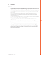
Preface........................................................................................... 3
1.1General. ............................................... . . . . . . . . . . . . . . . . . . . . . . . . . . . . . . . . . . . . . . . . . . . . . . . . . . . . . . . . . . . . . . . . . . . . . . . . . . . . . . . . . . . . . . . . 3
2.
Product introduction................................................................... 4
2.1 Operation control and connectors. . . . . . . . . . . . . . . . . . . . . . . . . . . . . . . . . . . . . . . . . . . . . . . . . . . . . . . . . . . . . . . . . . . . . . . . . . . . . . . . . . . 4
2.2 Connection of system.................... . . . . . . . . . . . . . . . . . . . . . . . . . . . . . . . . . . . . . . . . . . . . . . . . . . . . . . . . . . . . . . . . . . . . . . . . . . . . . . . . . . . . . . . . 5
2.3 4-roll wire feed mechanism. ........ . . . . . . . . . . . . . . . . . . . . . . . . . . . . . . . . . . . . . . . . . . . . . . . . . . . . . . . . . . . . . . . . . . . . . . . . . . . . . . . . . . . . . . . . 6
3.Installation.................................................................................... 7
EN
3.1
3.2
3.3
3.4
3.5
3.6
3.7
3.8
3.9
Assembly of MIG/MAG system. .. . . . . . . . . . . . . . . . . . . . . . . . . . . . . . . . . . . . . . . . . . . . . . . . . . . . . . . . . . . . . . . . . . . . . . . . . . . . . . . . . . . . . . . . . 7
Mounting of MIG welding gun... . . . . . . . . . . . . . . . . . . . . . . . . . . . . . . . . . . . . . . . . . . . . . . . . . . . . . . . . . . . . . . . . . . . . . . . . . . . . . . . . . . . . . . . . 7
Mounting and locking of wire spool.. . . . . . . . . . . . . . . . . . . . . . . . . . . . . . . . . . . . . . . . . . . . . . . . . . . . . . . . . . . . . . . . . . . . . . . . . . . . . . . 7
Automatic wire feed to gun........ . . . . . . . . . . . . . . . . . . . . . . . . . . . . . . . . . . . . . . . . . . . . . . . . . . . . . . . . . . . . . . . . . . . . . . . . . . . . . . . . . . . . . . . . 8
Adjustment of pressure................. . . . . . . . . . . . . . . . . . . . . . . . . . . . . . . . . . . . . . . . . . . . . . . . . . . . . . . . . . . . . . . . . . . . . . . . . . . . . . . . . . . . . . . . . 8
Adjustment of tightness of spool brake. . . . . . . . . . . . . . . . . . . . . . . . . . . . . . . . . . . . . . . . . . . . . . . . . . . . . . . . . . . . . . . . . . . . . . . . . 8
Burn back time. ................................ . . . . . . . . . . . . . . . . . . . . . . . . . . . . . . . . . . . . . . . . . . . . . . . . . . . . . . . . . . . . . . . . . . . . . . . . . . . . . . . . . . . . . . . . 8
Ground cable..................................... . . . . . . . . . . . . . . . . . . . . . . . . . . . . . . . . . . . . . . . . . . . . . . . . . . . . . . . . . . . . . . . . . . . . . . . . . . . . . . . . . . . . . . . . 8
Shield gas. .......................................... . . . . . . . . . . . . . . . . . . . . . . . . . . . . . . . . . . . . . . . . . . . . . . . . . . . . . . . . . . . . . . . . . . . . . . . . . . . . . . . . . . . . . . . . 9
3.9.1 Installing gas bottle. ................. . . . . . . . . . . . . . . . . . . . . . . . . . . . . . . . . . . . . . . . . . . . . . . . . . . . . . . . . . . . . . . . . . . . . . . . . . . . . . . . . . . . . . . . . 9
3.10 Main switch I/O. ............................... . . . . . . . . . . . . . . . . . . . . . . . . . . . . . . . . . . . . . . . . . . . . . . . . . . . . . . . . . . . . . . . . . . . . . . . . . . . . . . . . . . . . . . 10
3.11 Operation of cooling unit, FastCool 10. . . . . . . . . . . . . . . . . . . . . . . . . . . . . . . . . . . . . . . . . . . . . . . . . . . . . . . . . . . . . . . . . . . . . . . . . 10
3.12Hanging.............................................. . . . . . . . . . . . . . . . . . . . . . . . . . . . . . . . . . . . . . . . . . . . . . . . . . . . . . . . . . . . . . . . . . . . . . . . . . . . . . . . . . . . . . . 10
4.
5.
6.
7.
2
Service, operation disturbances............................................... 10
Disposal of the machine............................................................. 10
Ordering numbers...................................................................... 11
Technical data............................................................................. 12
FastMig MF 33
1.
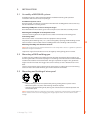
PREFACE
1.1 General
Congratulations on choosing the FastMig MF equipment. Used correctly, Kemppi products can
significantly increase the productivity of your welding, and provide years of
economical service.
This operating manual contains important information on the use, maintenance and safety of
your Kemppi product. The technical specifications of the equipment can be found at the end
of the manual.
Please read the manual carefully before using the equipment for the first time. For your
own safety and that of your working environment, pay particular attention to the safety
instructions in the manual.
For more information on Kemppi products, contact Kemppi Oy, consult an authorised Kemppi
dealer, or visit the Kemppi web site at www.kemppi.com.
The specifications presented in this manual are subject to change without prior notice.
Important notes
Items in the manual that require particular attention in order to minimise damage and
personal harm are indicated with the ’NOTE!’ notation. Read these sections carefully and follow
their instructions.
EN
Disclaimer
While every effort has been made to ensure that the information contained in this guide
is accurate and complete, no liability can be accepted for any errors or omissions. Kemppi
reserves the right to change the specification of the product described at any time without
prior notice. Do not copy, record, reproduce or transmit the contents of this guide without
prior permission from Kemppi.
© Kemppi Oy / 1152
3
2.
PRODUCT INTRODUCTION
FastMig MF is basic wire feeder designed for demanding enviroment. It can be used with
Kemppi's basic FastMig power sources KM 300, KM 400, and KM 500.
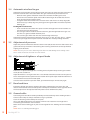
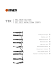
2.1 Operation control and connectors
1.
4.
5.
2.
EN
6.
3.
1.
2.
3.
Operation panel
Connection of welding gun EURO
Lead-in and clamping of cooling liquid
hoses
4.
5.
6.
Shielding gas connection
Connection for control cable
Welding current cable connection
4T
1.
2T
3
2
5
6
4
7
3
8
9
1
2
5
6
7
8
0
10
0
10
MIN
MAX
MIN
MAX
MF
1.
2.
3.
4
Selection of gun switch function
Adjustment of wire feed speed
Adjustment of welding voltage
FastMig MF 33
2.
3.
9
1
W001320
4
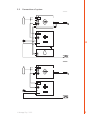
2.2 Connection of system
EN
© Kemppi Oy / 1152
5
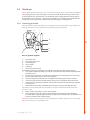
2.3 4-roll wire feed mechanism
Wire ø, mm
Fe, 0,6...0,8
Mc,
Fc
Ss,
Al
EN
Wire guide tube ø, mm
white
1,0 mm
3134140
orange
2,0 mm
3134120
plastic
2,0 mm
4267220
yellow
2,4 mm
4268210
plastic
2,0 mm
4266970
for Promig 511
0,9...1,6
orange
2,0 mm
3133700
plastic
4,0 mm
4270180
1,6...2,4
blue
4,0 mm
3134130
blue
4,0 mm
3134110
brass
4,0 mm
4267030
0,8...1,6
silver
2,5 mm
3134290
silver
2,5 mm
3134300
plastic
2,0 mm
4267220
1,6...2,4
yellow
3,0 mm
3134710
yellow
3,0 mm
3134720
plastic
4,0 mm
4270180
yellow
3,0 mm
4268560
Feed rolls, 4-rolls
Colour
ø, mm
white
0,6/0,8
3133810
white
0,8/0,8 (L)
3143180
red
1,0/1,2
3133210
red
1,0/1,0 (L)
3138650
orange
1,2/1,2(L)
3137390
yellow
1,4-1,6/2,0
3133820
yellow
1,6/1,6 (L)
3141120
black
2,4
3133880
blue
3,2
3133910
red
1,0/1,2
3133940
orange
1,2/1,2 (L)
3137380
yellow
1,4-1,6/2,0
3133990
yellow
1,6/1,6 (L)
3141130
black
2,4
3134030
blue
3,2
3134060
Fe, Fc, Mc,
Ss, Al
orange
1,2/1,2 (L)
3142210
Gear wheel
brown
1,4/1,4 (L)
3142220
ø 28 mm
(0–18 m/min)
4265240
plastic
Trapetsoid
groove
yellow
1,6/1,6 (L)
3142200
ø 28 mm
(0–18 m/min)
4287860
steel
grey
2,0/2,0 (L)
3142230
ø 40 mm
(0–25 m/min)
4265250
plastic
black
2,4 (L)
3142240
ø 40 mm
(0–25 m/min)
4297270
steel
Fe, Ss, Al
Plain, V-groove
Fe, Fc, Mc
Knurled,
V-groove
(L) = Fitted with ball bearings
6
FastMig MF 33
Feed roll groove selection
Transfer of gear wheel selector plate
3.
INSTALLATION
3.1 Assembly of MIG/MAG system
Assemble the units in order mentioned below and follow mounting and operation
instructions which are delivered in packages.
Installation of power source
Read paragraph: ”Installation” in operation instructions for FastMig power sources and carry
out the installation according to that.
Mounting of KM power sources to transport wagon
Read and follow the instructions given in the transport cart installation/assembly manual
Mounting the FastMig MF on to the power source
Screw the fastening pivot on the power source. Lift the wire feeder on fastening pivot.
Connecting cables
Connect the cables in accordance with the equipment notes provided.
The polarity of the welding wire (+ or -) can be changed by replacing the MF welding current
cable and return current cable with the FastMig power source welding cable connector.
EN
Mounting of FastMig wire feed units to boom
NOTE! Wire feed unit must be mounted to boom in such a way that its chassis is galvanic separated
both from swing arm and boom.
Suspension angle of wire feed unit can be changed by moving fixing point in handle.
3.2 Mounting of MIG welding gun
In order to ensure trouble-free welding check in operation instructions of gun used by you
that wire guide tube and contact tip of gun are according to manufacturer’s recommendation
suitable to be used for wire feed diameter and type in question. To tight a wire guide tube
might cause for wire feed unit a bigger stress than normally as well as disturbances in wire
feed.
Screw snap connector of gun tight that there won’t come any voltage losses on connecting
surface. A loose connection will heat gun and wire feed unit and feeder.
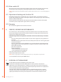
3.3 Mounting and locking of wire spool
LOCKEDOPEN
• Release locking nails of wire spool hub by turning locking knob a quarter round.
• Mount the spool at its place. Note rotating direction of spool!
• Lock the spool with locking knob, locking nails of hub remain to outside position and
will lock the spool.
NOTE! Check that in filler wire spool there are no parts sticking out, which could e.g. chafe against
chassis or door of wire feed unit. Dragging parts might expose chassis of wire feed unit under
voltage.
© Kemppi Oy / 1152
7
3.4 Automatic wire feed to gun
Automatic wire feed makes change of wire spool more rapid. In spool change the pressure of
feed rolls need not to be released and filler wire goes automatically to correct wire line.
• Make sure that groove of feed roll matches the diameter of welding wire used.
• Release the wire end from spool and cut off the bent length. Be careful that the wire
does not spill from the spool to sides!
• Straighten about 20 cm of the wire and see that the end of it has no sharp edges (file
off if necessary). A sharp edge may damage the wire guide tube and contact tip of the
welding gun.
FastMig MF wire feed units:
• Draw a bit of loose wire from wire spool. Feed wire through back liner to feed rolls. Do
not release pressure of feed rolls!
• Press the gun switch and feed a bit wire until wire goes through feed rolls to gun. See
that wire is in grooves of both feed roll pairs!
• Press still the gun switch until wire has come through contact tip.
Automatic feed may sometimes fail with thin wires (Fe, Fc, Ss: 0,6 – 0,8 mm, Al: 0,8 – 1,0 mm).
In that case you might have to open feed rolls and feed wire manually through feed rolls.
EN
3.5 Adjustment of pressure
Adjust the pressure of feed rolls with the control screw (20) so that the wire is fed into the wire
guide tube evenly and allows a little braking when coming out from the contact tip without
slipping at the feed rolls.
NOTE! Excessive pressure causes flattening of the filler wire and damage to the coating. It also
causes undue wear of the feed rolls as well as friction.
3.6 Adjustment of tightness of spool brake
A
Brake force is adjusted through hole in locking device of spool hub by screwing the control
screw (A) with screwdriver.
Adjust brake force as so big that the wire is not allowed to become too loose on the spool so
that it would spill from the spool when the rotation of the spool stops. Need for brake force is
increased with increase of wire feed speed.
Since the brake loads for its part the motor, you shouldn’t keep it unnecessarily tight.
3.7 Burn back time
Electronics of feed unit controls stopping of welding automatically so that the wire end
doesn’t melt fastened to the contact tip or the work piece. Automatics work regardless of the
wire feed speed. Can be adjusted also from power source SETUP-menu ('PoC').
3.8 Ground cable
Connecting of earth cable should be preferably connected directly to the welding material.
Contact surface of press always should be as large as possible.
Clean the fastening surface from paint and rust!
Use in your MIG equipment at least 70 mm². Thinner cross-sectional areas might cause
overheating of connectors and insulations.
Make sure that the welding gun in your use is designed for max. welding current needed by
you!
NOTE! Never use a damaged welding gun!
8
FastMig MF 33
3.9 Shield gas
NOTE! Handle gas bottle with care. There is a risk for injury if gas bottle or bottle valve is damaged!
For welding stainless steels, mixed gases are normally used. Check that the gas bottle valve
is suitable for the gas. The flow rate is set according to the welding power used in the job. A
suitable flow rate is normally 8 – 10 l/min. If the gas flow is not suitable, the welded joint will
be sporous. Contact your local Kemppi-dealer for choosing gas and equipment.
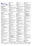
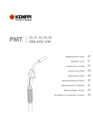
3.9.1 Installing gas bottle
NOTE! Always fasten gas bottle properly in vertical position in a special holder on the wall or on a
carriage. Remember to close gas bottle valve after having finished welding.
A
F
C
G
B
EN
E
D
Parts of gas flow regulator
A. Gas bottle valve
B. Press regulation screw
C. Connecting nut
D. Hose spindle
E. Jacket nut
F. Gas hose pressure meter
The following installing instructions are valid for most of the gas flow regulator types:
1. Step aside and open the bottle valve (A) for a while to blow out possible impurities from
the bottle valve.
2. Turn the press regulation screw (B) of the regulator until no spring pressure can be felt.
3. Close needle valve, if there is one in the regulator.
4. Install the regulator on bottle valve and tighten connecting nut (C) with a wrench.
5. Install hose spindle (D) and jacket nut (E) into gas hose and tighten with hose clamp.
6. Connect the hose with the regulator and the other end with the wire feed unit. Tighten
the jacket nut.
7. Open bottle valve slowly. Gas bottle pressure meter (F) shows the bottle pressure.
NOTE! Do not use the whole contents of the bottle. The bottle should be filled when the bottle
pressure is 2 bar.
8. Open needle valve if there is one in the regulator.
9. Turn regulation screw (B) until hose pressure meter (G) shows the required flow (or
pressure). When regulating flow amount, the power source should be in switched on and
the gun switch pressed simultaneously.
NOTE! Close bottle valve after having finished welding. If the machine will be out of use for a long
time, unscrew the pressure regulation screw.
© Kemppi Oy / 1152
9
3.10 Main switch I/O
When you turn the main switch of the FastMig™ power source into I-position, the pilot lamp
closest to this switch will light up, indicating the power source is ready for welding.
NOTE! Always start and switch off the machine with the main switch, never use the mains plug as a
switch.
3.11 Operation of cooling unit, FastCool 10
Operation of cooling unit is controlled in such a way that pump is started when welding is
started. After welding stop pump is rotating for approx. 5 min cooling the gun and the cooling
liquid to ambient temperature.
Read in operation instructions for the FastCool 10 unit the trouble situations of the liquid
circulation system and protection against torch etc. damage.
3.12 Hanging
MF 33 can be hanged from the handle to the barrier.
EN
4.
SERVICE, OPERATION DISTURBANCES
The amount of use and the working environment should be taken into consideration when
planning the frequency of maintenance of MF. Careful use and preventive maintenance will
help to ensure trouble-free operation.
The following maintenance operations should be carried out at least every six months:
Check:
• The wear of the grooves of the feed rolls. Excessive wear of grooves causes problems in
wire feed.
• The wear of the wire guide tubes of wire feed. Badly worn feed rolls and wire guide tubes
should be discarded.
• The wire guide tube in the gun should be set as near the feed rolls as possible, but not
touching them and the wire must follow a straight line from the end of the tube to the
groove of the feed roll.
• Spool brake adjustment.
• Electric connections
- Oxidised couplings must be cleaned
- Loose couplings must be tightened
Clean dust and dirt from the equipment.
Lubricate the feed rolls twice a year.
NOTE! When using compressed air, always protect your eyes with proper eye protection.
In case of problems contact your KEMPPI dealer.
5.
DISPOSAL OF THE MACHINE
Do not dispose of electrical equipment with normal waste!
In observance of European Directive 2002/96/EC on waste electrical and electronic
equipment, and its implementation in accordance with national law, electrical equipment
that has reached the end of its life must be collected separately and taken to an appropriate
environmentally responsible recycling facility.
The owner of the equipment is obliged to deliver a decommissioned unit to a regional
collection centre, per the instructions of local authorities or a Kemppi representative. By
applying this European Directive you will improve the environment and human health.
10
FastMig MF 33
6.
ORDERING NUMBERS
MF 33
6063300
KM 300
3-ph 400V
6033000
KM 400
3-ph 400V
6034000
KM 500
3-ph 400V
6035000
Cooling unit FastCool 10
6068100
Transport unit PM 500
6185291
Accessories
KWF 300 protection slides
6185287
MIG-guns
MMT 25
3m
6252513MMT
MMT 25
4,5 m
6252514MMT
MMT 27
3m
6252713MMT
MMT 27
4,5 m
6252714MMT
MMT 32
3m
6253213MMT
MMT32
4,5 m
6253214MMT
MMT 35
3m
6253513MMT
MMT 35
4,5 m
6253514MMT
MMT 42
3m
6254213MMT
MMT 42
4,5 m
6254214MMT
MMT 30W
3m
6253043MMT
MMT 30W
4,5 m
6253044MMT
MMT 42W
3m
6254203MMT
MMT 42W
4,5 m
6254204MMT
MMT 52W
3m
6255203MMT
MMT 52W
4,5 m
6255204MMT
EN
Interconnecting cables
KM 70-1.8-WH
6260411
KM 70-15-WH
6260412
KM 70-1.8-GH
6260413
KM 70-15-GH
6260414
© Kemppi Oy / 1152
11
7.
TECHNICAL DATA
MF 33
Operating voltage (safety voltage)
Connection capacity
Output 40 °C
Wire feed mechanism
Diameter of feed roll
Wire feed speed ¹)
Filler wires
Wire spool
EN
Gun connection
Operation temperature range
Storage temperature range
EMC class
Degree of protection
External dimensions
Weight
24 V DC
100 W
60 % ED
520 A
100 % ED
440 A
4-roll feed
32 mm
0 – 25 m/min
ø Fe, Ss
0.6 – 1.6
ø Cored wire
0.8 – 2.0
ø Al
1.0 – 2.4
max. weight
20 kg
max. ø
ø 300 mm
Euro
-20 ... +40 °C
-40 ... +60 °C
A
IP23S
LxWxH
590x240x445 mm
13.6 kg
¹) Changes of speed are carried out by changing gear wheel (D 28/D 40).
12
FastMig MF 33
KEMPPI OY
Kempinkatu 1
PL 13
FIN-15801 LAHTI
FINLAND
Tel +358 3 899 11
Telefax +358 3 899 428
[email protected]
www.kemppi.com
KEMPPI (UK) Ltd
Martti Kemppi Building
Fraser Road
Priory Business Park
BEDFORD, MK44 3WH
UNITED KINGDOM
Tel +44 (0)845 6444201
Telefax +44 (0)845 6444202
[email protected]
Kotimaan myynti:
Tel +358 3 899 11
Telefax +358 3 734 8398
[email protected]
KEMPPI FRANCE S.A.S.
65 Avenue de la Couronne des Prés
78681 EPONE CEDEX
FRANCE
Tel +33 1 30 90 04 40
Telefax +33 1 30 90 04 45
[email protected]
KEMPPI SVERIGE AB
Box 717
S-194 27 UPPLANDS VÄSBY
SVERIGE
Tel +46 8 590 783 00
Telefax +46 8 590 823 94
[email protected]
KEMPPI NORGE A/S
Postboks 2151, Postterminalen
N-3103 TØNSBERG
NORGE
Tel +47 33 346000
Telefax +47 33 346010
[email protected]
KEMPPI DANMARK A/S
Literbuen 11
DK-2740 SKOVLUNDE
DANMARK
Tel +45 4494 1677
Telefax +45 4494 1536
[email protected]
KEMPPI BENELUX B.V.
Postbus 5603
NL-4801 EA BREDA
NEDERLAND
Tel +31 765717750
Telefax +31 765716345
[email protected]
KEMPPI GmbH
Otto-Hahn-Straße 14
D-35510 BUTZBACH
DEUTSCHLAND
Tel +49 6033 88 020
Telefax +49 6033 72 528
[email protected]
OOO KEMPPI
Polkovaya str. 1, Building 6
127018 MOSCOW
RUSSIA
Tel +7 495 739 4304
Telefax +7 495 739 4305
[email protected]
ООО КЕМППИ
ул. Полковая 1, строение 6
127018 Москва
Tel +7 495 739 4304
Telefax +7 495 739 4305
[email protected]
KEMPPI, TRADING (BEIJING) COMPANY,
LIMITED
Room 420, 3 Zone, Building B,
No.12 Hongda North Street,
Beijing Economic Development Zone,
100176 Beijing
CHINA
Tel +86-10-6787 6064
+86-10-6787 1282
Telefax +86-10-6787 5259
[email protected]
KEMPPI SPÓŁKA Z O.O.
Ul. Borzymowska 32
03-565 WARSZAWA
POLAND
Tel +48 22 7816162
Telefax +48 22 7816505
[email protected]
肯倍贸易(北京)有限公司
中国北京经济技术开发区宏达北路12号
创新大厦B座三区420室 (100176)
KEMPPI AUSTRALIA PTY LTD.
13 Cullen Place
P.O. Box 5256, Greystanes NSW 2145
SMITHFIELD NSW 2164
AUSTRALIA
Tel. +61 2 9605 9500
Telefax +61 2 9605 5999
[email protected]
KEMPPI INDIA PVT LTD
LAKSHMI TOWERS
New No. 2/770,
First Main Road,
Kazura Garden,
Neelankarai,
CHENNAI - 600 041
TAMIL NADU
Tel +91-44-4567 1200
Telefax +91-44-4567 1234
[email protected]
电话: +86-10-6787 6064
+86-10-6787 1282
传真: +86-10-6787 5259
[email protected]
1906340
1152
www.kemppi.com