1
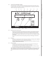
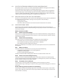
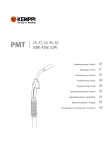
FastMig
KM 400 MVU
Operating manual • English
EN
Bruksanvisning • Norsk
NO
OPERATING MANUAL
English
EN
FastMig KM 400 MVU / © Kemppi Oy / 1045
FastMig KM 400 MVU / © Kemppi Oy / 1045
CONTENTS
1.
PREFACE....................................................................................... 3
1.1General. ............................................... . . . . . . . . . . . . . . . . . . . . . . . . . . . . . . . . . . . . . . . . . . . . . . . . . . . . . . . . . . . . . . . . . . . . . . . . . . . . . . . . . . . . . . . . 3
1.2Introduction. ..................................... . . . . . . . . . . . . . . . . . . . . . . . . . . . . . . . . . . . . . . . . . . . . . . . . . . . . . . . . . . . . . . . . . . . . . . . . . . . . . . . . . . . . . . . . 4
2.INSTALLATION............................................................................. 5
2.1
2.2
2.3
2.4
Positioning of the machine. ........ . . . . . . . . . . . . . . . . . . . . . . . . . . . . . . . . . . . . . . . . . . . . . . . . . . . . . . . . . . . . . . . . . . . . . . . . . . . . . . . . . . . . . . . . 5
Distribution network...................... . . . . . . . . . . . . . . . . . . . . . . . . . . . . . . . . . . . . . . . . . . . . . . . . . . . . . . . . . . . . . . . . . . . . . . . . . . . . . . . . . . . . . . . . 5
Connection to mains...................... . . . . . . . . . . . . . . . . . . . . . . . . . . . . . . . . . . . . . . . . . . . . . . . . . . . . . . . . . . . . . . . . . . . . . . . . . . . . . . . . . . . . . . . . 5
Welding and earthing cables. ..... . . . . . . . . . . . . . . . . . . . . . . . . . . . . . . . . . . . . . . . . . . . . . . . . . . . . . . . . . . . . . . . . . . . . . . . . . . . . . . . . . . . . . . . . 6
3.
MACHINE USE.............................................................................. 6
3.1 Starting of the power source. ..... . . . . . . . . . . . . . . . . . . . . . . . . . . . . . . . . . . . . . . . . . . . . . . . . . . . . . . . . . . . . . . . . . . . . . . . . . . . . . . . . . . . . . . . . 6
3.2 Front panel indicators.................... . . . . . . . . . . . . . . . . . . . . . . . . . . . . . . . . . . . . . . . . . . . . . . . . . . . . . . . . . . . . . . . . . . . . . . . . . . . . . . . . . . . . . . . . 6
3.3 Use of the control panel................ . . . . . . . . . . . . . . . . . . . . . . . . . . . . . . . . . . . . . . . . . . . . . . . . . . . . . . . . . . . . . . . . . . . . . . . . . . . . . . . . . . . . . . . . 7
3.3.1 Starting of the control panel.... . . . . . . . . . . . . . . . . . . . . . . . . . . . . . . . . . . . . . . . . . . . . . . . . . . . . . . . . . . . . . . . . . . . . . . . . . . . . . . . . . . . . . . . . 7
3.3.2Displays..................................... . . . . . . . . . . . . . . . . . . . . . . . . . . . . . . . . . . . . . . . . . . . . . . . . . . . . . . . . . . . . . . . . . . . . . . . . . . . . . . . . . . . . . . . . 7
3.3.3 Control knobs. .......................... . . . . . . . . . . . . . . . . . . . . . . . . . . . . . . . . . . . . . . . . . . . . . . . . . . . . . . . . . . . . . . . . . . . . . . . . . . . . . . . . . . . . . . . . 7
3.3.4 Adjustment of MIG dynamics (arc force).. . . . . . . . . . . . . . . . . . . . . . . . . . . . . . . . . . . . . . . . . . . . . . . . . . . . . . . . . . . . . . . . . . . . . . . . 8
3.3.5 Gas test. ..................................... . . . . . . . . . . . . . . . . . . . . . . . . . . . . . . . . . . . . . . . . . . . . . . . . . . . . . . . . . . . . . . . . . . . . . . . . . . . . . . . . . . . . . . . . 8
3.3.6 Wire feed test. ........................... . . . . . . . . . . . . . . . . . . . . . . . . . . . . . . . . . . . . . . . . . . . . . . . . . . . . . . . . . . . . . . . . . . . . . . . . . . . . . . . . . . . . . . . . 8
3.3.7 Selection of liquid- or gas-cooled MIG gun.. . . . . . . . . . . . . . . . . . . . . . . . . . . . . . . . . . . . . . . . . . . . . . . . . . . . . . . . . . . . . . . . . . . 8
3.3.8 Retrieval of weld data............... . . . . . . . . . . . . . . . . . . . . . . . . . . . . . . . . . . . . . . . . . . . . . . . . . . . . . . . . . . . . . . . . . . . . . . . . . . . . . . . . . . . . . . . . 8
3.3.9 Selection of control panel. ....... . . . . . . . . . . . . . . . . . . . . . . . . . . . . . . . . . . . . . . . . . . . . . . . . . . . . . . . . . . . . . . . . . . . . . . . . . . . . . . . . . . . . . . . . 8
3.3.10 Setting of the MIG operating mode. . . . . . . . . . . . . . . . . . . . . . . . . . . . . . . . . . . . . . . . . . . . . . . . . . . . . . . . . . . . . . . . . . . . . . . . . . . . . . . . 8
3.3.11 Setting of operation parameters. . . . . . . . . . . . . . . . . . . . . . . . . . . . . . . . . . . . . . . . . . . . . . . . . . . . . . . . . . . . . . . . . . . . . . . . . . . . . . . . . . . . . 9
3.3.12 Calibration of the wire feed speed. . . . . . . . . . . . . . . . . . . . . . . . . . . . . . . . . . . . . . . . . . . . . . . . . . . . . . . . . . . . . . . . . . . . . . . . . . . . . . . . 10
4.TROUBLESHOOTING................................................................. 10
4.1
4.2
4.3
4.4
4.5
Overload (yellow indicator lit). ... . . . . . . . . . . . . . . . . . . . . . . . . . . . . . . . . . . . . . . . . . . . . . . . . . . . . . . . . . . . . . . . . . . . . . . . . . . . . . . . . . . . . . . 10
Control cable connector fuse...... . . . . . . . . . . . . . . . . . . . . . . . . . . . . . . . . . . . . . . . . . . . . . . . . . . . . . . . . . . . . . . . . . . . . . . . . . . . . . . . . . . . . . . 10
Electric network overvoltage or undervoltage.. . . . . . . . . . . . . . . . . . . . . . . . . . . . . . . . . . . . . . . . . . . . . . . . . . . . . . . . . 11
Missing phase in the electric network.. . . . . . . . . . . . . . . . . . . . . . . . . . . . . . . . . . . . . . . . . . . . . . . . . . . . . . . . . . . . . . . . . . . . . . . . . . 11
Machine error codes....................... . . . . . . . . . . . . . . . . . . . . . . . . . . . . . . . . . . . . . . . . . . . . . . . . . . . . . . . . . . . . . . . . . . . . . . . . . . . . . . . . . . . . . . 11
5.SERVICE...................................................................................... 12
5.1Cables................................................... . . . . . . . . . . . . . . . . . . . . . . . . . . . . . . . . . . . . . . . . . . . . . . . . . . . . . . . . . . . . . . . . . . . . . . . . . . . . . . . . . . . . . . 12
5.2 Power source..................................... . . . . . . . . . . . . . . . . . . . . . . . . . . . . . . . . . . . . . . . . . . . . . . . . . . . . . . . . . . . . . . . . . . . . . . . . . . . . . . . . . . . . . . 12
5.3 Regular maintenance..................... . . . . . . . . . . . . . . . . . . . . . . . . . . . . . . . . . . . . . . . . . . . . . . . . . . . . . . . . . . . . . . . . . . . . . . . . . . . . . . . . . . . . . . 12
5.4 Disposal of the machine............... . . . . . . . . . . . . . . . . . . . . . . . . . . . . . . . . . . . . . . . . . . . . . . . . . . . . . . . . . . . . . . . . . . . . . . . . . . . . . . . . . . . . . . 13
6.
7.
8.
EN
2
ORDERING NUMBERS............................................................... 13
TECHNICAL SPECIFICATIONS................................................... 13
WARRANTY POLICY................................................................... 14
PREFACE
1.1
GENERAL
Congratulations on your choice of the FastMig™ KM-series power source. Reliable and durable,
Kemppi products are affordable to maintain, and they increase your work productivity.
This user manual contains important information on the use, maintenance, and safety of
your Kemppi product. The technical specifications of the device can be found at the end of
the manual. Please read the manual carefully before using the equipment for the first time.
For your safety and that of your working environment, pay particular attention to the safety
instructions in the manual.
For more information on Kemppi products, contact Kemppi Oy, consult an authorised Kemppi
dealer, or visit the Kemppi Web site at www.kemppi.com.
The specifications presented in this manual are subject to change without prior notice.
Important notes
Items in the manual that require particular attention in order to minimise damage and
personal harm are indicated with the ’NOTE!’ notation. Read these sections carefully and follow
their instructions.
FastMig KM 400 MVU / © Kemppi Oy / 1045
1.
EN
3
FastMig KM 400 MVU / © Kemppi Oy / 1045
1.2
INTRODUCTION
The FastMig KM-series power source 400 is a MIG power source designed for demanding
professional use in the three-phase network. The power source has a control panel that allows
ready control of the functions of the power source and the wire feeder.
Overview of the power source
A11
A1
A8
A3
A2
A10
A4
A9
A7
A6
A5
Front view
A1
A2
A3
A4
A5
A6
A7
A8
A9
A10
A11
EN
4
Rear view
Control panel
Main switch (I/O) S11
Signal light (I/O) H11
Thermal warning light H12
Welding cable connection X11,13
Earth connection X12
Control cable connection X15
Mains cable input 01
Fuse for control cable connection (6.3 A slow)
Fan grills
Carrying handles
INSTALLATION
2.1
POSITIONING OF THE MACHINE
Place the machine on a firm, dry and level surface. Where possible, do not allow dust or other
impurities to enter the machines cooling air flow. Preferably site the machine above floor level;
for example on a suitable carriage unit.
Notes for positioning the machine
• The surface inclination should not exceed 15 degrees.
• Ensure the free circulation of the cooling air. There must be at least 20 cm of free space in
front of and behind the machine for cooling air to circulate.
• Protect the machine against heavy rain and direct sunshine.
NOTE! The machine should not be operated in the rain as the protection class of the machine,
IP23S, allows for outside preserving and storage only.
NOTE! Never aim metallic grinding spray/sparks towards the equipment.
2.2
DISTRIBUTION NETWORK
FastMig KM 400 MVU / © Kemppi Oy / 1045
2.
All regular electrical devices without special circuits generate harmonic currents into
distribution network. High rates of harmonic current may cause losses and disturbance to
some equipment.
This equipment complies with IEC 61000-3-12 provided that the short-circuit power Ssc
is greater than or equal to 4.7 MVA at the interface point between the user’s supply and
the public supply network. It is the responsibility of the installer or user of the equipment
to ensure, by consultation with the distribution network operator if necessary, that the
equipment is connected only to a supply with a short-circuit power Ssc greater than or equal
to 4.7 MVA.
2.3
CONNECTION TO MAINS
FastMig KM power sources are connected to the 230-V or 400-V three-phase network using
the mains cable supplied with the machine.
The machine is equipped with a five-metre mains cable that does not have a plug. Before use,
check the mains cable and install a mains plug. If the cable does not comply with the local
electrical regulations, replace it with a compliant cable. See ’Technical specifications’.
NOTE! The mains cable or plug may be installed or replaced by only an electrical contractor or
installer authorised to perform such operations.
Replacement of the mains cable
1.
2.
3.
4.
5.
Unscrew the mounting screws on the top and sides of the machine, and remove the case
by lifting it.
Disconnect the phase leads from connectors L1, L2, and L3, and disconnect the
protective earth lead.
Pass the cable to the machine through the inlet ring at the rear of the machine, and
secure the cable with a cable clamp.
Connect the cable’s phase leads to connectors L1, L2, and L3.
Connect the yellow-green protective earth lead to its connector.
NOTE! Do not connect the zero lead if you are using a five-lead cable.
The table below lists the fuse sizes for 100% load in a 400-V three-phase network with 4 x 10mm² cable.
Voltage
Fuse, slow
Cable
400 V
35 A
H07RN-F 4G10 (10 mm²)
230 V
50 A
H07RN-F 4G10 (10 mm²)
EN
5
FastMig KM 400 MVU / © Kemppi Oy / 1045
2.4
WELDING AND EARTHING CABLES
The device has a welding cable connection both in the front and in the rear. The positions of
the welding and earthing cable connections are shown earlier in section ‘Introduction’.
The welding cable type to be used is rubber-insulated copper cable. The recommended crosssurfaces of the cables are as follows:
Model
Cross-surface
KM 400
70 … 90 mm²
The table below shows the typical load capacities of the cables when the ambient
temperature is 25° C and the lead temperature is 85° C.
Cable
Duty cycle (ED)
Voltage loss / 10 m
100 %
60 %
35 %
20 %
50 mm²
285 A
316 A
371 A
458 A
0,35 V / 100 A
70 mm²
355 A
403 A
482 A
602 A
0,25 V / 100 A
95 mm²
430 A
498 A
606 A
765 A
0,18 V / 100 A
120 mm²
500 A
587 A
721 A
917 A
0,21 V / 100 A
NOTE! Do not overload the welding cables, as an overload may cause voltage loss and
overheating.
Connect the earth clamp directly to the work piece in such a way as to maximise the contact
surface of the clamp. The point of connection must be unpainted and free of corrosion.
3.
MACHINE USE
3.1
STARTING OF THE POWER SOURCE
Start the power source by turning the main switch (S11) on the front panel to the ‘I’ position.
The standby indicator (H11) turns on. The control panel and wire feeder are not operational
yet, and the text ‘OFF’ is shown on the control panel display.
NOTE! Always turn the device on and off using the main switch, not via the mains socket.
The cooling fan is started for a moment when the main switch is turned to the ‘I’ position. The
fan turns off after a while and then restarts during welding when the machine has warmed up
sufficiently. The fan continues running even after up to 10 minutes of welding, depending on
the temperature of the machine.
3.2
FRONT PANEL INDICATORS
The following indicators can be found on the front panel of the device:
• When the green indicator, H11, is on, the power source is in standby mode. This indicator
is on when the machine is connected to the mains supply with the main switch in the ‘I’
position.
• When the yellow overheating indicator (H12) is on, the machine has overheated. The fan
then starts. When the indicator turns off, the machine can be used again.
• When indicator H12 blinks, the machine has experienced a failure. Attempt to remedy
the problem according to the instructions in Section 4, ‘Troubleshooting’. If the failure
cannot be eliminated, turn off the machine, and turn it on again. If the failure persists,
write down any fault code that may be shown on the display and contact authorised
Kemppi service agent.
EN
6
USE OF THE CONTROL PANEL
FastMig KM 400 MVU / © Kemppi Oy / 1045
3.3
The control panel is used for controlling and monitoring the operation of the power source
and the wire feeder. The buttons are used for adjusting functions. The displays and indicators
reflect the operating modes of the machine.
P1
P2
P3
P4
DYNAMICS
P5
GAS TEST
weld
data
P6
P7
P8
WIRE INCH
m/min
A
V
4T
2T
SETUP
REMOTE
LOCAL
KM
P9
P10
P11
W001319
P12
3.3.1 Starting of the control panel
• When you start the power source with the main switch (S11), the control panel remains
in OFF mode and the wire feeder is not operational. The display shows the text ‘OFF’.
• When you depress the start button (1) for at least one second, the control panel starts.
The unit is now ready for welding and enters the mode that was active before the power
was cut off.
• You can also start the control panel by quickly pressing the welding gun switch three
times.
3.3.2 Displays
• When you are adjusting the machine settings, the control panel displays show adjustable
operation parameters, their values, and the units of measure.
• During welding, display 2 shows the welding current value that is currently in use, while
display 8 shows the welding voltage.
3.3.3 Control knobs
• The left-hand control knob (10) allows adjustment of the speed of wire feeding. The
selected speed is shown on the display on the left-hand side (2).
• The control knob on the right-hand side (11) allows you to adjust the welding voltage.
The selected voltage is shown on the right-hand display (8).
These adjusters are used also for selecting the values of the machine’s operational parameters,
such as the MIG mode and set-up features. A parameter for adjustment is selected with the
left-hand knob (10), while the value of the parameter is selected with the right-hand knob
(11).
7
EN
FastMig KM 400 MVU / © Kemppi Oy / 1045
3.3.4 Adjustment of MIG dynamics (arc force)
When you press button 3, you can adjust the MIG welding dynamics of the machine by means
of the right-hand knob, 11. The welding dynamics setting affects the properties of the welding
arc and the amount of spatter as follows:
• The value 0 is the recommended basic setting.
• Use values -1 … -9 if you want a softer arc and less spatter.
• Use values 1 … 9 if you want a rougher and more stable arc. This setting is useful when
you are using 100% CO2 shielding gas when welding steel.
3.3.5 Gas test
The gas test button (5) opens the gas valve without activating the wire feed or power source.
By default, gas flows for 20 seconds. The gas flow time remaining is shown on the display.
The right-hand knob (11) allows you to set the default gas flow time, between 10 and 60
seconds, and store the new default value in the machine’s memory. To abort the gas test, press
the start button or gun switch.
3.3.6 Wire feed test
When you press the Wire inch button, 6, the wire feeder engine starts but the gas valve does
not open and the power source is not activated. The default wire feed speed is 5 m/min, and
you can adjust the speed with the right-hand knob. When the button is released, the wire
feeding stops. The machine automatically goes back to the normal state after approximately
five seconds from release of the button or immediately when you press the start button.
3.3.7 Selection of liquid- or gas-cooled MIG gun
You can select a MIG gun cooled with liquid or gas by pressing buttons 3 and 5 simultaneously
and holding them down for at least one second.
• When the display reads ‘GAS’, you can use a gas-cooled MIG gun with the equipment.
• When the display reads ‘COOLEr’, you can use a liquid-cooled MIG gun with the
equipment.
You can change the gun selection by pressing buttons 3 and 5 again, as above. With a liquidcooled gun selected, the liquid cooling function is started when the power source is started
the next time.
3.3.8 Retrieval of weld data
The weld data function allows you to return to the welding current and voltage used during
the previous session, with the weld data feature. To use the feature, press buttons 5 and 7
simultaneously.
3.3.9 Selection of control panel
Button 12 allows you to switch control between the control panels in the power source and
wire feeder. The indicator shows which of the control panels is in use.
• When the ‘LOCAL’ light is on, the wire feeding speed and welding current are set using
knobs 10 and 11 of the power source control panel.
• When the ‘REMOTE’ light is on, the wire feed speed and welding current are set using the
control panel of the wire feeder. Knobs 10 and 11 of the power source are disabled in this
mode.
EN
3.3.10 Setting of the MIG operating mode
Button 9 allows you to set the MIG welding gun to either two-sequence or four-sequence
mode. The indicator shows the mode selected.
• In two-sequence mode (2T), welding is started by pressing the gun switch and stopped
by releasing the switch.
• In four-sequence mode (4T), the following actions take place:
1. When you press the gun switch, the shielding gas starts to flow.
2. When you release the switch, welding starts.
3. When you press the switch again, welding ends.
4. When you release the switch again, the flow of the shielding gas ends.
8
Button 9 also is used for changing welding parameters as follows:
• Depress button 9 for at least five seconds. The set-up menu appears on display 2.
• Select the parameter to adjust with the left-hand knob (10) so that the name of the
parameter you want to adjust is shown on display 2.
• Set a value for the parameter by using the right-hand knob (11) such that the value
you want is shown on display 2. The value you selected is recorded in the control panel
memory.
• Exit the set-up menu by pressing button 9 again and holding for at least five seconds or
by briefly pressing the control panel start button (1).
The table below lists the operation parameters and their possible values.
Name of parameter
Name displayed
Parameter values
Factory setting Description
Pre Gas Time
PrG
0.0 … 9.9 s
(0.1 s)
Pre-welding gas time in
seconds
Post Gas Time
PoG
Aut, 0.1 … 32.0 s
(Aut)
Post-welding gas time in
seconds or automatically
according to welding current
1 s / 100 A (Aut)
Creep Start Level
CrE
10 … 170%
(50%)
Initial wire feeding speed as
a percentage of the pre-set
value:10% = creep start,
100% = no creep start,
170% = rush start
Start Power
StA
-9 … +9
(0)
Strength of initial pulse
Post Current Time
PoC
-9 … +9
(0)
Post-welding current time
Remote Switch
rS
2t4, Inc
(2t4)
Selection of wire feed device
switch operation
Calibration Menu
CAL
– – –, Ent
(– – –)
Wire feed speed calibration
(see instructions in sub
section 3.4)
LongSystem Mode
LSy
on, OFF
(OFF)
Select ‘on’ if you are using
long (>40 m) connector
cables
Restore Factory Settings
FAC
OFF, PAn, All
(OFF)
Restore factory settings; exit
the menu by selecting ’All’
FastMig KM 400 MVU / © Kemppi Oy / 1045
3.3.11 Setting of operation parameters
EN
9
FastMig KM 400 MVU / © Kemppi Oy / 1045
3.3.12 Calibration of the wire feed speed
When factory settings are used, the wire feed speed can be adjusted to between 4 and 100
without a unit of measurement. Only the LED symbol indicates that wire feed speed is the
parameter to be set.
The unit of the wire feed speed (m/min) is shown once the wire feed speed of the device has
been calibrated. To programmatically calibrate the wire feed speed:
1. To prepare the welding equipment for calibrating, do the following:
• Connect the wire feeder to the power source with the control cable.
• Insert the filler wire in the gun, and run the wire out of the contact tip.
• Adjust the feeder wheels so that they are sufficiently tight.
• Start the power source and turn on the control panel with the start button, 1.
2. Depress button 9 (SETUP) for at least five seconds. The set-up menu appears on the
display.
3. Select the calibration menu (CAL) by rotating the left-hand knob, and then select the
value ’Enter’ (Ent) with the right-hand knob. Accept your selection by pressing button 12
(REMOTE/LOCAL) briefly.
4. Use the right-hand knob to select ‘m/min’ as the value of measure for the quantity to be
calibrated, and accept your selection by briefly pressing button 12 (REMOTE/LOCAL).
5. Use the left-hand knob to set the first calibration point to the desired value (e.g., 2.0 m/
min).
6. Cut the filler wire at the contact tip end. Press the trigger, and let the wire run until it
stops automatically.
7. Measure the length of the loose wire end to an accuracy of 1 cm.
8. Enter the measurement with the right-hand knob, and accept your selection by pressing
button 12 (REMOTE/LOCAL) briefly.
9. Use the left-hand knob to set the second calibration point to an appropriate value (e.g.,
18.0 m/min).
10. Repeat steps 6–8.
11. The message ‘Suc cES’ appears on the display to indicate that calibration has ended
successfully. At the same time, the device exits calibration mode and returns to basic
operation mode.
4.
TROUBLESHOOTING
In the event of a failure of the machine, contact an authorised Kemppi service agent. Before
taking your unit for servicing, check the list below.
4.1
OVERLOAD (YELLOW INDICATOR LIT)
Two simultaneously operating fans cool the power source. The machine may, however,
overheat if continuously loaded above the rated values or if the circulation of cooling air is
prevented.
The yellow indicator (H12) is lit in the event of overheating. You then need to stop welding
and let the machine cool down. The indicator light turns off when welding can be resumed.
4.2
CONTROL CABLE CONNECTOR FUSE
The rear wall of the power source contains fuse F11, which protects the control cable
connector, X15. Using an incorrect fuse may cause damage to the power source. It is
important that you always use the right kind of fuse. The type and size of the fuse are
indicated next to the fuse socket.
EN
10
ELECTRIC NETWORK OVERVOLTAGE OR UNDERVOLTAGE
If the power source is used in an electric network with insufficient voltage (less than 300 V),
the control features of the device are disabled automatically.
The primary circuits of the power source are protected against power spikes. The product’s
mains voltage range is broad enough to prevent overvoltage problems at up to 440 V (see
Section 8, ‘Technical specifications’). Make sure that the voltage remains within the allowed
range, especially if the operating power is supplied by a generator set.
4.4
MISSING PHASE IN THE ELECTRIC NETWORK
If a phase is missing from the mains current, the welding features will be adversely affected or
the machine may have problems starting. Loss of a phase can be caused by a:
• Blown mains fuse.
• Damaged mains cable.
• Poor mains cable connection in the machine’s terminal block or mains socket.
4.5
MACHINE ERROR CODES
The machine always checks its operation automatically during start-up and reports any
failures detected. If failures are detected during start-up, they are shown as error codes on the
control panel display.
FastMig KM 400 MVU / © Kemppi Oy / 1045
4.3
Power source error codes
Err3
Power source overvoltage
The machine has stopped the welding because it has detected momentary voltage spikes or
continuous overvoltage dangerous to the machine in the electric network. Check the quality
of the network supply.
Err4
Power source overheating
The power source has overheated. The cause might be one of the following:
• The power source has been used for a long time at maximum power.
• The circulation of cooling air to the power source is blocked.
• The cooling system has experienced a failure.
Remove any obstacle to air circulation, and wait until the power source fan has cooled down
the machine.
Err5
Water unit alarm
The water circulation is blocked. The cause may be one of the following:
• Congestion or disconnection in the cooling pipeline.
• Insufficient cooling liquid.
• Excessive cooling liquid temperature.
Check the circulation of the cooling liquid and the air circulation of the water unit.
Err23 Power source overvoltage warning
The power source has detected voltage spikes in the electric network. Short power spikes
can be managed. They do not lead to interruptions in welding but may decrease the welding
quality. Check the quality of the supply network.
Err61 The water unit is not found
The water unit is not connected to the equipment, or the connection has failed.
Set the machine to gas cooling (3.3.7) if you are using a gas-cooled welding gun, or connect a
water unit.
Err155 Warning of the wire feed unit overheating
The voltage level of the wire feeding engine has increased. The cause may be a stained wire
lead or a gun cable that is twisted at a sharp angle. Check the state of the gun, and clean the
wire line if this is necessary.
11
EN
FastMig KM 400 MVU / © Kemppi Oy / 1045
Err154 Overloading of the wire feed motor
The welding has been interrupted because the wire feeding engine power has risen to a high
level. The cause may be congestion in the wire line. Check the wire lead, contact tip, and feed
rollers.
Err201 Use of PMT gun is prevented
The machine is intended for use with MMT guns. When a PMT gun is used, the gun’s jumpers
must be set to ‘FU’. This error code may appear also if the contacts of the gun trigger are
stained or there are problems with the trigger leads. Check the trigger’s leads.
Other error codes:
The machine can show codes not listed here. In the event of an unlisted code appearing,
contact an authorised Kemppi service agent and report the error code shown.
5.
SERVICE
The utilisation level of the power source and its working environment should be taken into
consideration in planning the frequency of maintenance of the machine. Appropriate use and
preventive maintenance guarantee the trouble-freest use of the equipment. This allows you to
avoid interruptions in use and increases the productivity of the machine.
5.1
CABLES
Check the condition of welding and mains cables daily. Do not use damaged cables. Also
make sure that all extension cables used in the mains connection are in proper condition and
compliant with regulations.
NOTE! The mains cables may be repaired and installed only by electrical contractors and installers
authorised to perform such operations.
5.2
POWER SOURCE
Before cleaning the interior of the machine, you need to remove the case by unscrewing the
mounting screws at the top and sides of the machine.
NOTE! To prevent damage, wait approximately two minutes after disconnecting the mains cable
before removing the machine’s case.
Perform the following cleaning and maintenance at least every six months:
1. Clean the interior of the machine and the fan grill’s net of any dust and stains – for
example, with a soft brush and vacuum cleaner.
• Do not use pressurised air. The stain may become compressed into the grooves of the
coolers.
• Do not use a pressure-washing device.
2. Check the electrical connections of the machine. Clean any oxidised connections, and
tighten the loosened ones.
• Check for the right tension before you start repairing the connections.
NOTE! Remember that the machine may be repaired only by an electrical contractor or installer
authorised to perform such operations.
5.3
REGULAR MAINTENANCE
Authorised Kemppi service agents perform regular maintenance by agreement.
Tasks included in regular maintenance:
• Cleaning of equipment.
• Inspection and maintenance of the welding gun.
• Checking of connectors, switches, and control knobs.
• Checking of electrical connections.
• Checking of the mains cable and plug.
• Replacement of damaged or worn parts.
• Calibration testing, with adjustment of the functions and operational values of the
machine, if necessary.
EN
12
DISPOSAL OF THE MACHINE
Do not dispose of electrical equipment with normal waste!
In observance of European Directive 2002/96/EC on waste electrical and electronic
equipment, and its implementation in accordance with national law, electrical equipment
that has reached the end of its life must be collected separately and taken to an appropriate
environmentally responsible recycling facility.
The owner of the equipment is obliged to deliver a decommissioned unit to a regional
collection centre, per the instructions of local authorities or a Kemppi representative. By
applying this European Directive you will improve the environment and human health.
6.
ORDERING NUMBERS
Item
Size
FastMig™ KM 400 MVU
7.
Part number
603400003
Earthing cable
5 m, 50 mm²
6184511
Earthing cable
5 m, 70 mm²
6184711
Transport unit
6185291
Gun holder GH 30
6256030
FastMig KM 400 MVU / © Kemppi Oy / 1045
5.4
TECHNICAL SPECIFICATIONS
FastMig™ KM 400 MVU
400 V
230 V
Mains voltage, 3~50/60 Hz
400 V , 15...+20%
230 V, 10 ... +10%
80% ED
19 kVA
20 kVA
100% ED
18 kVA
18 kVA
80% ED I1max.
27 A
48 A
100% ED I1
26 A
45 A
4G10 (10 mm²)
4G10 (10 mm²)
35 A
50 A
Rated power
Primary current
Connector cable Fuse, slow (recommended)
Load capacity at 40 ° C
H07RN-F
80% ED 400 A
400 A
100% ED 380 A
380 A
Welding voltage range MIG
10 … 39 V
10 … 39 V
Max. welding voltage
48 V
48 V
Open circuit voltage
65 V
65 V
Idle power
30 W
30 W
Efficiency
87%
87%
Power factor
0.8
0.8
Storage temperature range
-40 ... 60 º C
-40 ... 60 º C
Operating temperature range
-20 ... 40 º C
-20 ... 40 º C
Degree of protection
IP 23S
IP 23S
EMC class
A
A
Minimun short circuit power Ssc of supply network*
4.7 MVA
4.7 MVA
Length 590 mm
590 mm
Width 230 mm
230 mm
Height 580 mm
580 mm
External dimensions
Weight
Voltage supply for auxiliary devices
* See paragraph 2.2
49 kg
49 kg
24 VDC
24 VDC
EN
13
FastMig KM 400 MVU / © Kemppi Oy / 1045
8.
WARRANTY POLICY
Kemppi Oy provides a warranty for products manufactured and sold by the company if defects
in materials or workmanship occur. Warranty repairs are to be carried out only by an authorised
Kemppi Service Agent. Packing, shipping, and insurance are at the orderer’s expense.
The warranty starts on the date of purchase. Spoken promises not included in the terms of
warranty are not binding on the warrantor.
Limitations of the warranty
The following conditions are not covered under the terms of warranty: defects arising
from normal wear and tear, non-compliance with operation and maintenance instructions,
overloading, negligence, connection to incorrect or faulty supply voltage (including voltage
surges outside equipment specifications), incorrect gas pressure, anomalies or failures in the
electric network, transport or storage damage, and fire or damage due to forces of nature. This
warranty does not cover direct or indirect travel costs, daily allowances, or accommodation
related to warranty service.
The warranty does not cover welding torches and their consumables, feeder drive rolls, and
feeder guide tubes. Direct or indirect damage caused by a defective product is not covered
under the warranty.
The warranty becomes void if modifications are made to the machine that are not approved
by the manufacturer or if non-original spare parts are used in repairs. The warranty is also
voided if repairs are carried out by a repair agent not authorised by Kemppi.
Undertaking warranty repairs
Warranty defects must be reported to Kemppi or an authorised Kemppi Service Agent without
delay.
Before a warranty repair is undertaken, the customer must present proof of warranty or
otherwise prove the validity of the warranty in writing. The proof must indicate the date of
purchase and the manufacturing number of the unit to be repaired. The parts replaced under
the terms of this warranty remain the property of Kemppi and must be returned to Kemppi if
requested.
After a warranty repair, the warranty of the machine or equipment, repaired or replaced, shall
be continued to the end of the original warranty period.
EN
14
EN
15
FastMig KM 400 MVU / © Kemppi Oy / 1045
KEMPPI OY
PL 13
FIN-15801 LAHTI
FINLAND
Tel +358 3 899 11
Telefax +358 3 899 428
www.kemppi.com
KEMPPIKONEET OY
PL 13
FIN-15801 LAHTI
FINLAND
Tel +358 3 899 11
Telefax +358 3 734 8398
e-mail: myynti.fi @kemppi.com
KEMPPI SVERIGE AB
Box 717
S-194 27 UPPLANDS VÄSBY
SVERIGE
Tel +46 8 590 783 00
Telefax +46 8 590 823 94
e-mail: [email protected]
KEMPPI NORGE A/S
Postboks 2151, Postterminalen
N-3103 TØNSBERG
NORGE
Tel +47 33 346000
Telefax +47 33 346010
e-mail: [email protected]
KEMPPI DANMARK A/S
Literbuen 11
DK-2740 SKOVLUNDE
DANMARK
Tel +45 4494 1677
Telefax +45 4494 1536
e-mail:[email protected]
KEMPPI BENELUX B.V.
Postbus 5603
NL-4801 EA BREDA
NEDERLAND
Tel +31 765717750
Telefax +31 765716345
e-mail: [email protected]
KEMPPI FRANCE S.A.S.
65 Avenue de la Couronne des Prés
78681 EPONE CEDEX
FRANCE
Tel +33 1 30 90 04 40
Telefax +33 1 30 90 04 45
e-mail: [email protected]
KEMPPI GmbH
Otto-Hahn-Straße 14
D-35510 BUTZBACH
DEUTSCHLAND
Tel +49 6033 88 020
Telefax +49 6033 72 528
e-mail: [email protected]
KEMPPI SPÓŁKA Z O.O.
Ul. Borzymowska 32
03-565 WARSZAWA
POLAND
Tel +48 22 7816162
Telefax +48 22 7816505
e-mail: [email protected]
KEMPPI AUSTRALIA PTY LTD.
25A, Stennett Road
INGLEBURN NSW 2565
AUSTRALIA
Tel. +61 2 9605 9500
Telefax +61 2 9605 5999
e-mail: [email protected]
OOO KEMPPI
Polkovaya str. 1, Building 6
127018 MOSCOW
RUSSIA
Tel +7 495 739 4304
Telefax +7 495 739 4305
e-mail: [email protected]
ООО КЕМППИ
ул. Полковая 1, строение 6
127018 Москва
Tel +7 495 739 4304
Telefax +7 495 739 4305
e-mail: [email protected]
KEMPPI, TRADING (BEIJING) COMPANY,
LIMITED
Room 420, 3 Zone, Building B,
No.12 Hongda North Street,
Beijing Economic Development Zone,
100176 Beijing
CHINA
Tel +86-10-6787 6064
+86-10-6787 1282
Telefax +86-10-6787 5259
e-mail: [email protected]
肯倍贸易(北京)有限公司
中国北京经济技术开发区宏达北路12号
创新大厦B座三区420室 (100176)
电话: +86-10-6787 6064
+86-10-6787 1282
传真: +86-10-6787 5259
e-mail: [email protected]
KEMPPI INDIA PVT LTD
LAKSHMI TOWERS
New No. 2/770,
First Main Road,
KAZURA Gardens,
Neelangarai,
CHENNAI - 600 041
TAMIL NADU
1903300
1045
www.kemppi.com
KEMPPI (UK) Ltd
Martti Kemppi Building
Fraser Road
Priory Business Park
BEDFORD, MK44 3WH
ENGLAND
Tel +44 (0)845 6444201
Telefax +44 (0)845 6444202
e-mail: [email protected]