1
MITSUBISHI ELECTRIC
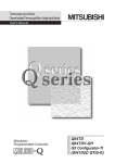
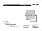
MELSEC System Q
Programmable Logic Controllers
User's Manual
Channel Isolated Thermocouple/
Micro Voltage Input Modules
Q64TD, Q64TDV-GH
GX Configurator-TI
Art. no.: 139837
15 05 2004
SH (NA)-080141
Version F
MITSUBISHI ELECTRIC
INDUSTRIAL AUTOMATION
• SAFETY PRECAUTIONS •
(Always read these instructions before using this equipment.)
Before using this product, please read this manual and the relevant manuals introduced in this manual
carefully and pay full attention to safety to handle the product correctly.
The instructions given in this manual are concerned with this product. For the safety instructions of the
PLC system, please read the user's manual for the CPU module to use.
In this manual, the safety instructions are ranked as "DANGER" and "CAUTION".
DANGER
Indicates that incorrect handling may cause hazardous conditions,
resulting in death or severe injury.
! CAUTION
Indicates that incorrect handling may cause hazardous conditions,
resulting in medium or slight personal injury or physical damage.
!
Note that the ! CAUTION level may lead to a serious consequence according to the circumstances.
Always follow the instructions of both levels because they are important to personal safety.
Please store this manual in a safe place and make it accessible when required. Always forward it to the
end user.
[DESIGN PRECAUTION]
!
DANGER
• Do not write data into the "system area" of the buffer memory of intelligent function modules.
Also, do not use any "prohibited to use" signals as an output signal to an intelligent function
module from the PLC CPU.
Writing data into the "system area" or outputting a signal for "prohibited to use" may cause a
PLC system malfunction.
!
CAUTION
• Do not bunch the control wires or communication cables with the main circuit or power wires, or
install them close to each other.
They should be installed 100mm(3.94inch) or more from each other.
Not doing so could result in noise that may cause malfunction.
A-1
A-1
[INSTALLATION PRECAUTIONS]
!
CAUTION
• Use the PLC in an environment that meets the general specifications contained in the user's
manual of the CPU module to use.
Using this PLC in an environment outside the range of the general specifications may cause
electric shock, fire, malfunction, and damage to or deterioration of the product.
• While pressing the installation lever located at the bottom of module, insert the module fixing tab
into the fixing hole in the base unit until it stops. Then, securely mount the module with the fixing
hole as a supporting point.
Improper installation may result in malfunction, breakdown or the module coming loose and
dropping.
Securely fix the module with screws if it is subject to vibration during use.
• Tighten the screws within the range of specified torque.
If the screws are loose, it may cause the module to fallout, short circuits, or malfunction.
If the screws are tightened too much, it may cause damage to the screw and/or the module,
resulting in fallout, short circuits or malfunction.
• Switch all phases of the external power supply off when mounting or removing the module.
Not doing so may cause damage to the module.
In the system where a CPU module supporting the online module change is used and on the
MELSECNET/H remote I/O stations, modules can be replaced online (during energizing).
However, there are some restrictions on replaceable modules and the replacement procedures
are predetermined for each module.
For details, refer to the chapter of the online module change in this manual.
• Do not directly touch the conductive area or electronic components of the module.
Doing so may cause malfunction or failure in the module.
[WIRING PRECAUTIONS]
!
CAUTION
• Always ground the FG terminal for the PLC.
There is a risk of electric shock or malfunction.
• When turning on the power and operating the module after wiring is completed, always attach
the terminal cover that comes with the product.
There is a risk of electric shock if the terminal cover is not attached.
• Tighten the terminal screws within the range of specified torque.
If the terminal screws are loose, it may result in short circuits or malfunction.
If the terminal screws are tightened too much, it may cause damage to the screw and/or the
module, resulting in short circuits or malfunction.
• Be careful not to let foreign matter such as sawdust or wire chips get inside the module.
They may cause fires, failure or malfunction.
• The top surface of the module is covered with protective film to prevent foreign objects such as
cable offcuts from entering the module when wiring.
Do not remove this film until the wiring is complete.
Before operating the system, be sure to remove the film to provide adequate ventilation.
• Always place the thermocouple at least 100mm(3.94inch) away from the main circuit cables and
AC control lines.
Fully keep it away from high-voltage cables and circuits which include harmonics, such as an
inverter's load circuit.
Not doing so will make the module more susceptible to noises, surges and inductions.
A-2
A-2
[STARTING AND MAINTENANCE PRECAUTIONS]
!
CAUTION
• Do not disassemble or modify the modules.
Doing so could cause failure, malfunction injury or fire.
• Switch all phases of the external power supply off when mounting or removing the module.
Not doing so may cause damage to the module.
In the system where a CPU module supporting the online module change is used and on the
MELSECNET/H remote I/O stations, modules can be replaced online (during energizing).
However, there are some restrictions on replaceable modules and the replacement procedures
are predetermined for each module.
For details, refer to the chapter of the online module change in this manual.
• Do not mount/remove the module onto/from base unit more than 50 times (IEC 61131-2compliant), after the first use of the product.
Failure to do so may cause the module to malfunction due to poor contact of connector.
• Do not touch the connector while the power is on.
Doing so may cause malfunction.
• Switch all phases of the external power supply off when cleaning or retightening the terminal
screws and module installation screws.
Not doing so may cause failure or malfunction of the module.
If the screws are loose, it may cause the module to fallout, short circuits, or malfunction.
If the screws are tightened too much, it may cause damages to the screws and/or the module,
resulting in the module falling out, short circuits or malfunction.
• Always make sure to touch the grounded metal to discharge the electricity charged in the body,
etc., before touching the module.
Failure to do so may cause a failure or malfunctions of the module.
[DISPOSAL PRECAUTIONS]
!
CAUTION
• When disposing of this product, treat it as industrial waste.
A-3
A-3
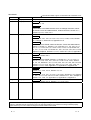
REVISIONS
The manual number is given on the bottom left of the back cover.
Print Date
Nov., 2000
Jun., 2001
Manual Number
SH (NA)-080141-A First printing
SH (NA)-080141-B Addition
Revision
Selection 2.1, 2.2
Correction
Conformation to the EMC Directive and Low Voltage Instruction, About
the Generic Terms and Abbreviations, Product Structure, Section 3.1.1,
Feb., 2002
Section 5.2, 5.2.1, 5.2.2, 5.3.3
SH (NA)-080141-C Q64TDV-GH was added as a new model.
Addition
Section 3.1.2, 3.2.1, 3.2.3, 3.4.2, 3.4.10, 3.4.11, 3.4.20, 3.4.21, Section
5.6.3, Chapter 7, Section 8.2.8, Appendix 4 to 6
Correction
SAFETY PRECAUTIONS, About the Generic Terms and Abbreviations,
Chapter 1, Section 1.1, Section 2.1, 2.2, Section 3.1.1, 3.2, 3.2.2, 3.3.1,
3.3.2, 3.4.1, 3.4.3 to 3.4.9, 3.4.13 to 3.4.16, 3.4.18, 3.4.19, Section 4.2,
4.3, 4.4.1, 4.4.2, 4.5 to 4.7, Section 5.1, 5.2.1, 5.2.2, 5.4, 5.5, 5.6.1, 5.6.2,
Chapter 6, Chapter 8, Section 8.1, 8.2.1, 8.2.5 to 8.2.7, 8.2.9, Appendix 7
Feb., 2003
SH (NA)-080141-D Addition
Section 1.2, Section 5.6.4
Sep., 2003
Correction
SAFETY PRECAUTIONS, Section 2.1, Section 3.1.1, 3.1.2, 3.2, 3.3.1,
3.3.2, 3.4.1, 3.4.2, 3.4.4, 3.4.7, 3.4.8, 3.4.13 to 3.4.19, 3.4.21, Section
4.3, 4.5, 4.6, Section 5.1, 5.2.1, 5.2.2, 5.3.2, 5.3.3, 5.4, 5.5, 5.6.1 to 5.6.3,
Section 6.1, 6.1.1, 6.1.2, 6.2, 6.2.1, 6.2.2, 7.3.1, 7.3.3, 7.3.4, 7.3.6, 7.4,
Section 8.1, 8.2.1, 8.2.5, Appendix 4.1, Appendix 5.2, Appendix 5.3
SH (NA)-080141-E Addition
Section 3.4.1, 3.4.2, 3.4.21, Section 4.5, 4.6
May, 2004
Correction
Section 3.1.1, 3.1.2, 3.3.1, 3.3.2, 3.4.1 to 3.4.21, Section 4.5, 4.6, Section
5.1, 5.2.1, 5.3.1, 5.3.2, 5.5, 5.6.1 to 5.6.4, Section 6.1.1, 6.2.1, Chapter 7,
Section 7.3.4, 7.3.6, 7.4, Appendix 5.2, Appendix 5.3, Appendix 7
SH (NA)-080141-F Correction
Section 2.2, Section 3.4.14, Section 7.1, 7.3.1 to 7.3.6
Japanese Manual Version SH-080132-F
This manual confers no industrial property rights or any rights of any other kind, nor does it confer any patent
licenses. Mitsubishi Electric Corporation cannot be held responsible for any problems involving industrial property
rights which may occur as a result of using the contents noted in this manual.
2000 MITSUBISHI ELECTRIC CORPORATION
A-4
A-4
INTRODUCTION
Thank you for purchasing the MELSEC-Q series PLC.
Before using the equipment, please read this manual carefully to develop full familiarity with the functions
and performance of the Q series PLC you have purchased, so as to ensure correct use.
Please forward a copy of this manual to the end user.
CONTENTS
SAFETY PRECAUTIONS..............................................................................................................................AREVISIONS ....................................................................................................................................................AINTRODUCTION............................................................................................................................................AConformation to the EMC Directive and Low Voltage Instruction ................................................................AAbout the Generic Terms and Abbreviations ................................................................................................AProduct Lineup ...............................................................................................................................................A1 OVERVIEW
1
4
5
9
9
9
1- 1 to 1- 3
1.1 Features ................................................................................................................................................... 1- 2
1.2 Functions Added by Function Version C................................................................................................. 1- 3
2 SYSTEM CONFIGURATION
2- 1 to 2- 3
2.1 Applicable Systems.................................................................................................................................. 2- 1
2.2 How to Check the Function Version and Software Version.................................................................... 2- 3
3 SPECIFICATIONS
3- 1 to 3-34
3.1 Performance Specifications ..................................................................................................................... 3- 1
3.1.1 Specifications of Q64TD ................................................................................................................... 3- 1
3.1.2 Specifications of Q64TDV-GH .......................................................................................................... 3- 3
3.2 Function List ............................................................................................................................................. 3- 6
3.2.1 Micro voltage input/output conversion characteristic (Q64TDV-GH only)....................................... 3- 7
3.2.2 Temperature conversion system (Q64TD)....................................................................................... 3- 8
3.2.3 Temperature/micro voltage conversion system (Q64TDV-GH) ...................................................... 3- 9
3.3 I/O Signals Transferred to/from PLC CPU .............................................................................................. 3-10
3.3.1 I/O signal list ...................................................................................................................................... 3-10
3.3.2 I/O signal details ................................................................................................................................ 3-11
3.4 Buffer Memory.......................................................................................................................................... 3-16
3.4.1 Buffer memory assignment (Q64TD) ............................................................................................... 3-16
3.4.2 Buffer memory assignment (Q64TDV-GH) ...................................................................................... 3-19
3.4.3 Conversion enable/disable setting (Un\G0) ..................................................................................... 3-21
3.4.4 CH
time/count averaging setting (Un\G1 to 4) ............................................................................ 3-22
3.4.5 Averaging processing specification (Un\G9) .................................................................................... 3-22
3.4.6 Conversion completion flag (Un\G10) .............................................................................................. 3-23
3.4.7 CH
measured temperature value/micro voltage value (Un\G11 to 14) ...................................... 3-24
3.4.8 Error code (Un\G19).......................................................................................................................... 3-25
3.4.9 Setting range (Q64TD) (Un\G20) ..................................................................................................... 3-25
3.4.10 Setting range 1 (Q64TDV-GH) (Un\G20) ....................................................................................... 3-26
3.4.11 Setting range 2 (Q64TDV-GH) (Un\G21) ....................................................................................... 3-26
3.4.12 Warning output enable/disable setting (Un\G47) ........................................................................... 3-27
3.4.13 Warning output flag (Un\G48)....................................................................................................................3-27
3.4.14 Disconnection detection flag (Un\G49)........................................................................................... 3-28
A-5
A-5
scaling value (Un\G50 to 53) .........................................................................................................3-29
3.4.15 CH
scaling range upper/lower limit values (Un\G62 to 69)....................................................... 3-29
3.4.16 CH
3.4.17 CH
scaling width upper/lower limit values (Un\G78 to 85)........................................................ 3-30
3.4.18 CH
warning output upper/lower limit values
(Un\G86 to 101) .............................................................................................................................. 3-30
3.4.19 CH
offset/gain temperature value (Q64TD)/CH
offset/gain setting value
(Q64TDV-GH) (Un\G118 to 125) ................................................................................................... 3-32
3.4.20 Mode switching setting (Un\G158 to 159) ...................................................................................... 3-33
3.4.21 Factory default offset/gain value/User range settings offset/gain value/User range settings thermal
EMF offset/gain value (Un\G160 to 191) ....................................................................................... 3-34
4 SETUP AND PROCEDURES BEFORE OPERATION
4- 1 to 4-13
4.1 Handling Precautions............................................................................................................................... 4- 1
4.2 Setup and Procedures before Operation ................................................................................................ 4- 2
4.3 Part Names and Settings......................................................................................................................... 4- 3
4.4 Wiring........................................................................................................................................................ 4- 4
4.4.1 Wiring Instructions............................................................................................................................. 4- 4
4.4.2 External Wiring .................................................................................................................................. 4- 4
4.5 Switch Setting for Intelligent Function Module ........................................................................................ 4- 6
4.6 Offset/Gain Setting................................................................................................................................... 4- 8
4.7 Cold Junction Temperature Compensation Yes/No Setting................................................................... 4-13
5 UTILITY PACKAGE (GX Configurator-TI)
5- 1 to 5-21
5.1 Utility Package Functions ........................................................................................................................ 5- 1
5.2 Installing and Uninstalling the Utility Package......................................................................................... 5- 3
5.2.1 User precautions ............................................................................................................................... 5- 3
5.2.2 Operating environment...................................................................................................................... 5- 5
5.3 Explanation of Utility Package Operation................................................................................................ 5- 6
5.3.1 How to perform common utility package operations........................................................................ 5- 6
5.3.2 Operation overview ........................................................................................................................... 5- 8
5.3.3 Starting the intelligent function module utility ................................................................................... 5-10
5.4 Initial Setting ............................................................................................................................................. 5-12
5.5 Automatic Refresh Settings ..................................................................................................................... 5-13
5.6 Monitor/Test ............................................................................................................................................. 5-15
5.6.1 Monitor/test screen............................................................................................................................ 5-15
5.6.2 Offset/gain setting operation (Function version C or later) .............................................................. 5-18
5.6.3 Offset/gain setting operation (Function version B)........................................................................... 5-20
5.6.4 OMC (Online Module Change) refresh data .................................................................................... 5-21
6 PROGRAMMING
6- 1 to 6- 8
6.1 Programs Used in Normal System Configuration................................................................................... 66.1.1 Program example when utility package is used............................................................................... 66.1.2 Program example when utility package is not used......................................................................... 66.2 Programs Used on Remote I/O Network ................................................................................................ 66.2.1 Program example when utility package is used............................................................................... 66.2.2 Program example when utility package is not used......................................................................... 6-
A-6
A-6
1
2
3
4
5
7
7 ONLINE MODULE CHANGE
7- 1 to 7-34
7.1 Online Module Change Conditions.......................................................................................................... 7- 2
7.2 Online Module Change Operations ......................................................................................................... 7- 3
7.3 Online Module Change Procedure .......................................................................................................... 7- 4
7.3.1 When factory default is used and initial setting was made with GX Configurator-TI ...................... 7- 4
7.3.2 When factory default is used and initial setting was made with sequence program ...................... 7- 9
7.3.3 When user range setting is used and initial setting was made with GX Configurator-TI
(other system is available)................................................................................................................ 7-14
7.3.4 When user range setting is used and initial setting was made with GX Configurator-TI
(other system is unavailable)............................................................................................................ 7-19
7.3.5 When user range setting is used and initial setting was made with sequence program
(other system is available)................................................................................................................ 7-24
7.3.6 When user range setting is used and initial setting was made with sequence program
(other system is unavailable)............................................................................................................ 7-29
7.4 Range Reference Table........................................................................................................................... 7-34
7.5 Precautions for Online Module Change .................................................................................................. 7-34
8 TROUBLESHOOTING
8- 1 to 8- 5
8.1 Error Code List ......................................................................................................................................... 88.2 Troubleshooting ....................................................................................................................................... 88.2.1 RUN LED is extinguished ................................................................................................................. 88.2.2 RUN LED flickers .............................................................................................................................. 88.2.3 ERROR LED flickers ......................................................................................................................... 88.2.4 ERROR LED is lit .............................................................................................................................. 88.2.5 Disconnection detection flag (XC) has turned on............................................................................. 88.2.6 Measured temperature value/micro voltage conversion value cannot be read .............................. 88.2.7 Measured temperature value is abnormal........................................................................................ 88.2.8 Micro voltage conversion value is abnormal .................................................................................... 88.2.9 Checking the Q64TD/Q64TDV-GH status using GX Developer system monitor ........................... 8APPENDIX
1
2
2
2
2
2
3
3
3
3
4
App.- 1 to App.-44
Appendix 1 Usual Operation Limits and Superheated Operating Limits.................................................App.- 1
Appendix 2 Allowable Temperature Differences......................................................................................App.- 1
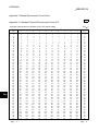
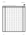
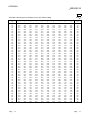
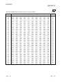
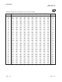
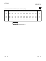
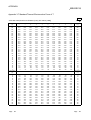
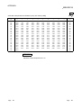
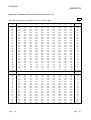
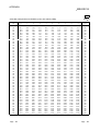
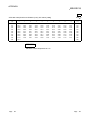
Appendix 3 Thermal Electromotive Force Chart ......................................................................................App.- 2
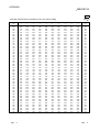
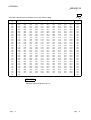
Appendix 3.1 Standard Thermal Electromotive Force of B..................................................................App.- 2
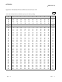
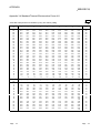
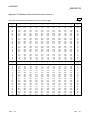
Appendix 3.2 Standard Thermal Electromotive Force of R .................................................................App.- 6
Appendix 3.3 Standard Thermal Electromotive Force of S..................................................................App.-10
Appendix 3.4 Standard Thermal Electromotive Force of K..................................................................App.-14
Appendix 3.5 Standard Thermal Electromotive Force of E..................................................................App.-18
Appendix 3.6 Standard Thermal Electromotive Force of J ..................................................................App.-21
Appendix 3.7 Standard Thermal Electromotive Force of T..................................................................App.-25
Appendix 3.8 Standard Thermal Electromotive Force of N .................................................................App.-27
Appendix 4 Upgrading of Q64TD/Q64TDV-GH Functions ......................................................................App.-31
Appendix 4.1 Comparison between Q64TD and Q64TDV-GH functions ...........................................App.-31
A-7
A-7
Appendix 5 Dedicated Instruction List ......................................................................................................App.-32
Appendix 5.1 OFFGAN .........................................................................................................................App.-33
Appendix 5.2 OGLOAD.........................................................................................................................App.-35
Appendix 5.3 OGSTOR.........................................................................................................................App.-38
Appendix 6 Differences between Q64TD and Q64TDV-GH ...................................................................App.-42
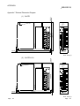
Appendix 7 External Dimension Diagram ................................................................................................App.-43
INDEX
A-8
Index- 1 to Index- 2
A-8
Conformation to the EMC Directive and Low Voltage Instruction
For details on making Mitsubishi PLC conform to the EMC directive and low voltage instruction when
installing it in your product, please see Chapter 3, "EMC Directive and Low Voltage Instruction" of the User's
Manual (Hardware) of the PLC CPU to use.
The CE logo is printed on the rating plate on the main body of the PLC that conforms to the EMC directive
and low voltage instruction.
BY making this product conform to the EMC directive and low voltage instruction, it is not necessary to make
those steps individually.
About the Generic Terms and Abbreviations
Unless otherwise specified, this manual uses the following general terms and abbreviations.
Abbreviation/general terms
Description of the abbreviation/general terms
Q64TD
Abbreviation of Q64TD thermocouple input module
Q64TDV-GH
Abbreviation of Q64TDV-GH channel isolated thermocouple/micro voltage input module
Personal computer
IBM PC/AT or compatible computer with DOS/V.
GX Developer
GX Configurator-TI
QCPU (Q mode)
QnPHCPU
®
Generic product name of the product types SWnD5C-GPPW-E, SWnD5C-GPPW-EA,
SWnD5C-GPPW-EV and SWnD5C-GPPW-EVA.
“n” in the model name is 4 or greater.
Generic term for thermocouple input module setting and monitor tool GX Configurator-TI
(SW1D5C-QTIU-E)
Generic term for Q00JCPU, Q00CPU, Q01CPU, Q02CPU, Q02HCPU, Q06HCPU,
Q12HCPU, Q25HCPU
Generic term for Q12PHCPU, Q25PHCPU
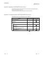
Product Lineup
The product lineup is given in the table below.
Type
Product
Quantity
Q64TD
Q64TD thermocouple input module
1
Q64TDV-GH
Q64TDV-GH channel isolated thermocouple/micro voltage input module
1
SW1D5C-QTIU-E
GX Configurator-TI Version 1 (Single license product)
(CD-ROM)
1
SW1D5C-QTIU-EA
GX Configurator-TI Version 1 (Volume license product)
(CD-ROM)
1
A-9
A-9
1 OVERVIEW
MELSEC-Q
1 OVERVIEW
1
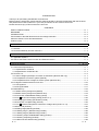
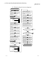
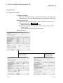
This user's manual provides the specifications, handling instructions, programming
procedures and others of the Q64TD thermocouple input module (abbreviated to the
Q64TD) and Q64TDV-GH channel isolated thermocouple/micro voltage input module
(abbreviated to the Q64TDV-GH) used with the MELSEC-Q series CPU module
(hereafter abbreviated to the PLC CPU).
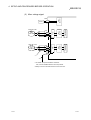
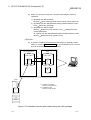
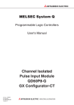
The Q64TD is a module designed to convert thermocouple input values from outside
the PLC into 16-bit signed binary measured temperature values and 16-bit signed
binary scaling values (ratios).
PLC CPU
Q64TD
(Buffer memory)
FROM
instruction
Initial setting
Cold junction
temperature
compensation RTD
Set data
Measured
temperature value,
scaling value
reading
Measured
temperature
value
Temperature measurement
TO
instruction
Scaling value
Measured
temperature
value
Scaling value
Pt100 temperature-measuring
resistor
Channel 1
Thermocouple input
Channel 4
Thermocouple input
: Refer to Section 3.4.15 for details of the scaling values.
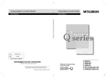
In addition to the temperature measurement functions of the Q64TD, the Q64TDV-GH
has a function that converts a micro voltage signal into a 16-bit, signed binary data.
PLC CPU
Q64TDV-GH
(Buffer memory)
Initial setting
Measured
temperature value,
Measured
temperature value/
micro voltage
conversion value
Scaling value
scaling value
FROM
instruction
Cold junction
temperature
compensation RTD
Set data
reading
Measured
temperature value/
micro voltage
conversion value
Scaling value
Temperature/micro voltage input
TO
instruction
Pt100 temperature-measuring
resistor
Channel 1
Thermocouple/micro voltage input
Channel 4
Thermocouple/micro voltage input
: Refer to Section 3.4.15 for details of the scaling value.
1-1
1-1
1 OVERVIEW
MELSEC-Q
1.1 Features
1
(1) Channels isolated
Both the Q64TD and Q64TDV-GH are channel isolated modules.
(2) 4 channels of temperatures measured by one module
One Q64TD module can measure temperatures of four channels.
It can also convert the detected temperature values into scaling values (ratios
(%)).
(3) Micro voltages of four channels can be converted on one module
(Q64TDV-GH only)
One Q64TDV-GH module can make micro voltage conversion of four channels.
It can also convert the detected micro voltage conversion values into scaling
values (ratio values (%)).
(4) Setting of conversion enable/disable
You can make a conversion enable/disable setting for each channel. Disabling
unused channels for conversion reduces sampling time.
It also prevents unnecessary disconnection detection on unused channels.
(5) Thermocouples conforming to JIS Standards usable
You can use eight different thermocouples (K, E, J, T, B, R, S, N) conforming to
the JIS Standards. You can also select the thermocouple type for each channel
using GX Developer.
(6) Disconnection detection
The disconnection of a thermocouple or compensation conductor can be
detected on each channel.
(7) Selection of sampling processing/time averaging processing/count
averaging processing
As a conversion processing method, you can choose sampling processing, time
averaging processing or count averaging processing on each channel.
(8) Pt100 temperature-measuring resistor for cold junction temperature
compensation
The Pt100 temperature-measuring resistor connected makes cold junction
temperature compensation automatically.
(9) Setting of Pt100 cold junction temperature compensation
enable/disable
Disabling cold junction temperature compensation with Pt100 temperaturemeasuring resistor enables cold junction temperature compensation to be made
outside the module.
If the ±1 °C cold junction temperature compensation accuracy of the Pt100
temperature-measuring resistor cannot be ignored, use of an external precision
ice bath improves the cold junction temperature compensation accuracy.
(10) Error compensation by offset/gain value setting
Error compensation can be made by setting offset and gain values on each
channel. As the offset and gain values, you can make selection from user range
setting and factory default setting.
1-2
1-2
1 OVERVIEW
MELSEC-Q
(11) Warning output
If the temperature detected is outside the preset measurement range, an warning
can be output on each channel.
(12) Online module change
You can perform a module change without stopping the system.
Further "inheritance of offset/gain settings to the new Q64TD/Q64TDV-GH after
online module change" and "transfer of offset/gain settings to the other
Q64TD/Q64TDV-GH mounted on the other slot" can be performed by executing
the dedicated instructions (G.OGLOAD, G.OGSTOR) or performing write to
buffer memory and turning the Y signal ON. (These functions are limited to
between the modules of the same model.)
(13) Utility package for ease of setting
The optional utility package (GX Configurator-TI) is available.
Though it is not required to use the utility package, the utility package allows you
to make initial setting and automatic refresh setting on-screen, reducing
sequence programs and facilitating the checking of the setting and operating
statuses.
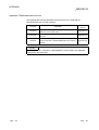
1.2 Functions Added by Function Version C
The functions added by the function Version C Q64TD are listed below.
Item
Online module change
Function overview
You can change the module without stopping the system.
The PLC CPU of function version C or later is required.
Using the mode switching setting (buffer memory addresses 158,
159: Un\G158, Un\G159) and operation condition setting request
(Y9), the module is switched between the normal mode and
offset/gain setting mode without the PLC CPU being reset.
Mode switching that does
Using the dedicated instruction (G.OFFGAN), the module is
not require PLC CPU to be
switched between the normal mode and offset/gain setting mode
reset
without the PLC CPU being reset.
Using GX Configurator-TI, the module is switched between the
normal mode and offset/gain setting mode without the PLC CPU
being reset.
Reference section
Chapter 7
Section 3.4.20
Appendix 5.1
Section 5.6.2
POINT
(1) Refer to Appendix 4.1 for the function comparison between function versions.
(2) Refer to Section 2.2 for the method of confirming the function version.
1-3
1-3
2 SYSTEM CONFIGURATION
MELSEC-Q
2 SYSTEM CONFIGURATION
2.1 Applicable Systems
This section describes the system configuration for the Q64TD/Q64TDV-GH.
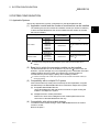
(1) Applicable module and the number of modules that can be installed
The following are the CPU module and network module (for remote I/O stations)
in which the Q64TD/Q64TDV-GH can be installed and the number of modules
that can be installed.
Applicable module
CPU module
Network module
Q00JCPU
Q00CPU
Q01CPU
Q02CPU
Q02HCPU
Q06HCPU
Q12HCPU
Q25HCPU
Q12PHCPU
Q25PHCPU
QJ72LP25-25
QJ72BR15
QJ72LP25G
QJ71LP25GE
Number of modules that
can be installed
Maximum 16
Maximum 24
Maximum 64
Maximum 64
Maximum 64
Remarks
( 1)
Can be installed in Q mode only
( 1)
( 1)
MELSECNET/H Remote I/O
station ( 2)
1 See User's Manual (Function Explanation, Program Fundamentals) for the CPU module to use.
2 See Q Corresponding MELSECNET/H Network System Reference Manual (Remote I/O
network).
(2) Base Unit in which the conversion module can be installed
The Q64TD/Q64TDV-GH can be installed in any I/O slot ( 3) of the base unit.
However, a power shortage may occur depending on the combination with other
installed modules and the number of modules used, so always take into
consideration the power supply capacity when installing modules.
3 Limited to the range of the number of I/O points in the CPU module and network module (for
remote I/O stations).
(3) Compatibility with a multiple PLC system
First read the QCPU (Q mode) user's manual (Function Explanation, Program
Fundamentals) if the Q64TD/Q64TDV-GH is used with a multiple PLC system.
(a) Compatible Q64TD/Q64TDV-GH
Use a Q64TD/Q64TDV-GH with function version B or higher if using the
module in a multiple PLC system.
(b) Intelligent function module parameters
Perform PLC write of the intelligent function module parameters to the
control PLC of the Q64TD/Q64TDV-GH only.
(4) Compatibility with online module change
To make an online module change, use the Q64TD/Q64TDV-GH of function
version C or later.
Refer to Chapter 7.
2-1
2-1
2
2 SYSTEM CONFIGURATION
MELSEC-Q
(5) Q64TD-compatible software packages
Correspondence between systems which use Q64TD and software packages are
as shown below.
The GX Developer is necessary when using a Q64TD.
Software Version
GX Configurator-TI
GX Developer
2
Q00J/Q00/Q01CPU
Q02/Q02H/Q06H/
Q12H/Q25HCPU
Q12PH/Q25PHCPU
Single PLC system
Version 7 or later
Multiple PLC system
Version 8 or later
Single PLC system
Version 4 or later
Multiple PLC system
Version 6 or later
Single PLC system
Multiple PLC system
If installed in a MELSECNET/H remote I/O station
4
Version 1.10L or later
Version 1.00A or later
Version 7.10L or later
Version 1.13P or later
Version 6 or later
Version 1.00A or later
4 The product of Version 1.14Q or earlier is not compatible with "normal mode - offset/gain setting
mode switching" and "OMC refresh data". Use the product of Version 1.15R or later.
(6) Q64TDV-GH-compatible software packages
Correspondence between systems which use Q64TDV-GH and software
packages are as shown below.
The GX Developer is necessary when using a Q64TDV-GH.
Software Version
GX Configurator-TI
GX Developer
Q00J/Q00/Q01CPU
Q02/Q02H/Q06H/
Q12H/Q25HCPU
Q12PH/Q25PHCPU
Single PLC system
Version 7 or later
Multiple PLC system
Version 8 or later
Single PLC system
Version 4 or later
Multiple PLC system
Version 6 or later
Single PLC system
Multiple PLC system
If installed in a MELSECNET/H remote I/O station
Version 1.13P or later
Version 7.10L or later
Version 6 or later
5 The product of Version 1.14Q or earlier is not compatible with " OMC refresh data". Use the
product of Version 1.15R or later.
POINT
The Q64TD of function version A is not available.
The Q64TDV-GH of function version B is not available.
The products of function version C include the functions of the products of function
version A and B.
2-2
5
2-2
2 SYSTEM CONFIGURATION
MELSEC-Q
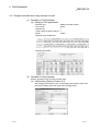
2.2 How to Check the Function Version and Software Version
This section describes how to check the function version of the Q64TD/Q64TDV-GH
and the GX Configuration-TI software version.
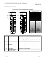
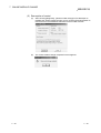
(1) How to check the function version of the Q64TD/Q64TDV-GH
(a) To check the version using the "SERIAL column of the rating plate" located
on the side of the module
Function version
Conformed standard
(b) To check the version using the GX Developer
See Section 8.2.9 of this manual.
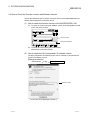
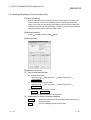
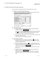
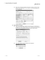
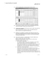
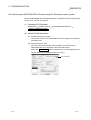
(2) How to check the GX Configuration-TI software version
The GX Configuration-TI software version can be checked on GX Developer's
"Product information" screen.
[Startup procedure]
GX Developer
"Help"
Product information
Software version
(In the case of GX Developer Version 7)
2-3
2-3
3 SPECIFICATIONS
MELSEC-Q
3 SPECIFICATIONS
3.1 Performance Specifications
The following are the performance specifications of the Q64TD/Q64TDV-GH.
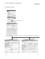
3.1.1 Specifications of Q64TD
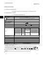
(1) Performance specification list
Item
3
Number of channels
Temperature conversion
Out
value
put
Scaling value
Specifications
4 channels
16-bit, signed binary
(-2700 to 18200: Value to the first decimal place
Standard with which thermocouple
conforms
Usable thermocouples and measured
temperature range accuracies
Cold junction temperature
compensation accuracy
JIS C1602-1995
Refer to Section (2)
1.0
Resolution
B,R,S,N : 0.3
Number of analog input points
Between thermocouple
input and earth
Between thermocouple
input channels
Between cold
junction temperature
compensation input
(Pt100) and earth
2
Isolation
method
Transformer
isolation
Transformer
isolation
Dielectric
withstand voltage
Isolation resistance
1780VrmsAC
/3 cycles
(Altitude 2000m)
100MΩ or more using 500VDC
isolation resistance tester
10MΩ or more using 500VDC
isolation resistance tester
—
—
No
insulation
Yes (Each channel independent)
16 points
Connection terminals
18-point terminal block
0.3 to 0.75mm2
Applicable wire size
1.25-3 R1.25-3(Sleeved crimping terminals are unusable)
Internal current consumption (5VDC)
0.50A
Weight
0.25kg
Outline dimensions
3
Max. 100 thousand times
Number of occupied points
Applicable crimping terminals
2
4 channels + Pt100 connection channel/module
Specific isolated area
E PROM write count
K,E,J,T : 0.1
40ms/channel
Conversion speed
Wire break detection
1
As per calculation expression marked
Accuracy
Isolation
10 times)
16-bit, signed binary
98(H)
27.4(W)
112(D)mm
1: Calculate the accuracy in the following method.
(Accuracy) = (conversion accuracy) + (temperature characteristic) (operating ambient temperature variation) + (cold junction
temperature compensation accuracy)
An operating ambient temperature variation indicates a deviation of the operating ambient temperature from the 25 5 range.
Example: When the thermocouple used is B (Refer to Section 3.1.1 (2)), the operating ambient temperature is 35 , and
the measured temperature is 1000 , the accuracy is: (25 5 ) + ( 0.4 ) (35 - 30 ) + ( 1 ) = 5.5
2: The conversion speed is a period from when a temperature is input and converted into a corresponding digital value until the value is
stored into the buffer memory. When two or more channels are used, the conversion speed is "40ms number of conversion enabled
channels".
3: At wire break detection, the temperature conversion value right before wire break occurrence is held.
3-1
3-1
3 SPECIFICATIONS
MELSEC-Q
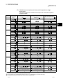
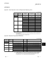
(2) Usable thermocouples and measured temperature range
accuracies
This section explains the usable thermocouples and measured temperature
range accuracies.
Usable
Thermoco
uple Type
Measured
Temperature
Range 1
Temperature Characteristic
Conversion Accuracy
(At operating ambient temperature (Per operating ambient temperature
variation of 1 )
25 5 )
——— 3
0 to 600
600 to 800
B
2
800 to 1700
1700 to 1820
12.5
——— 3
-50 to 0
——— 3
——— 3
——— 3
2.5
0.4
12.5
2.0
0.3
——— 3
——— 3
9.5
——— 3
——— 3
——— 3
——— 3
2.5
0.4
12.5
2.0
0.3
1600 to 1760
——— 3
——— 3
9.5
——— 3
-270 to -200
——— 3
——— 3
——— 3
2
2
300 to 1600
-50 to 0
0 to 300
2
2
300 to 1600
2.5
-200 to 0
2
Larger value of 0.5 and 0.5%
of measured temperature
Larger value of 0.06 and
0.2% of measured temperature
11.0
0 to 1200
2
Larger value of 0.5 and
0.25% of measured temperature
Larger value of 0.06 and
0.02% of measured temperature
9.0
K
1200 to 1370
——— 3
——— 3
——— 3
-270 to -200
——— 3
——— 3
——— 3
-200 to 0
2
Larger value of 0.5 and 0.5%
of measured temperature
Larger value of 0.06 and
0.15% of measured temperature
8.5
0 to 900
2
Larger value of 0.5 and
0.25% of measured temperature
Larger value of 0.06 and
0.02% of measured temperature
6.75
E
J
13.0
0.4
——— 3
1600 to 1760
S
3.0
——— 3
——— 3
0 to 300
R
2
——— 3
Max. Temperature Error at
Ambient Temperature 55
900 to 1000
——— 3
——— 3
——— 3
-210 to -40
——— 3
——— 3
——— 3
-40 to 750
2
Larger value of 0.5 and
0.25% of measured temperature
Larger value of 0.06 and
0.02% of measured temperature
5.625
750 to 1200
——— 3
——— 3
——— 3
-270 to -200
——— 3
——— 3
——— 3
-200 to 0
2
Larger value of 0.5 and 0.5%
of measured temperature
Larger value of 0.06 and
0.1% of measured temperature
6.0
0 to 350
2
Larger value of 0.5 and
0.25% of measured temperature
Larger value of 0.06 and
0.02% of measured temperature
2.625
T
350 to 400
——— 3
——— 3
——— 3
3
3
——— 3
———
-270 to -200
———
-200 to 0
2
Larger value of 0.5 and 0.5%
of measured temperature
Larger value of 0.06 and
0.2% of measured temperature
11.0
0 to 1250
2
Larger value of 0.5 and
0.25% of measured temperature
Larger value of 0.06 and
0.02% of measured temperature
9.375
N
3
——— 3
——— 3
——— 3
1250 to 1300
1: If a value entered from the thermocouple is outside the measured temperature range given in the table, it is handled as the
maximum/minimum value of the measured temperature range.
2: The accuracies only in the temperature ranges of Class 1 to 3 (shaded areas) in JIS C1602-1995 apply.
3: Temperature measurement can be made, but accuracy is not guaranteed.
3-2
3-2
3 SPECIFICATIONS
MELSEC-Q
3.1.2 Specifications of Q64TDV-GH
(1) Performance specifications
Item
Specifications
Number of channels
Temperature conversion
value
4 channels
16-bit, signed binary
(-2700 to 18200: Value to the first decimal place
Output Micro voltage conversion
value
16-bit signed binary (-25000 to 25000)
Scaling value
16-bit, signed binary
Standard with which thermocouple
conforms
JIS C1602-1995
Usable thermocouples and measured
temperature range accuracies
Refer to Section (2)
Cold junction temperature
compensation accuracy
1.0
-100mV to +100mV (input resistance 2MΩ or more)
Micro voltage input accuracy
Resolution
Thermocouple input
Refer to Section (3)
B:0.7
R,S:0.8
K,T:0.3
Sampling period
Number of analog input points
3
5V
Specific isolated area
E PROM write count
N:0.4
4 channels + Pt100 connection channel/module
Absolute maximum input
2
J:0.1
2
Sampling period 3
Conversion speed
Wire break detection
E:0.2
4 V
20ms/channel
Micro voltage input
Isolation
1
As per calculation expression marked
Thermocouple input accuracy
Micro voltage input range
10 times)
Between thermocouple
input/micro voltage
input and earth
Between thermocouple
input/micro voltage
input channels
Between cold junction
temperature
compensation input
(Pt100) and earth
Isolation method
Transformer
isolation
Transformer
isolation
Dielectric
withstand voltage
1780VrmsAC/3
cycles
(Altitude 2000m)
No insulation
Isolation resistance
100MΩ or more using
500VDC isolation resistance
tester
10MΩ or more using 500VDC
isolation resistance tester
—
Yes (Each channel independent)
—
4
Max. 100 thousand times
Number of occupied points
16 points
Connection terminals
18-point terminal block
0.3 to 0.75mm2
Applicable wire size
Applicable crimping terminals
1.25-3 R1.25-3(Sleeved crimping terminals are unusable)
Internal current consumption
(5VDC)
0.50A
Weight
0.25kg
Outline dimensions
98(H)
27.4(W)
112(D)mm
1: Calculate the accuracy in the following method.
(Accuracy) = (conversion accuracy) + (temperature characteristic)
(operating ambient temperature variation) + (cold junction
temperature compensation accuracy)
An operating ambient temperature variation indicates a deviation of the operating ambient temperature from the 25 5 range.
Example: When the thermocouple used is B (Refer to Section 3.1.2 (2)), the operating ambient temperature is 35 , and the
measured temperature is 1000 , the accuracy is: ( 3.5 ) + ( 0.4 )
(35 - 30 ) + ( 1 ) = 6.5
3-3
3-3
3 SPECIFICATIONS
MELSEC-Q
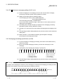
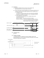
2: A period until a thermocouple input value/micro voltage input value is converted into a measured temperature value/micro voltage
conversion value.
3: A period until a thermocouple input value/micro voltage input value is converted into a measured temperature value/micro voltage
conversion value and the resultant value is stored into the buffer memory.
The conversion speed is a delay time that occurs during sampling processing. It is independent of averaging processing.
Example: When two channels are enabled for conversion
(Conversion speed) = (sampling period)
3
= (20ms
2 channels)
3
= 120ms
Input 2)
Input 1)
Conversion processing
CH1
CH2
CH1
CH2
CH1
CH2
CH1
CH2
CH1
Input 1)
Buffer memory
CH2
Input 2)
Conversion speed
Conversion speed
4: At wire break detection, the measured temperature value/micro voltage conversion value right before wire break occurrence is held.
3-4
3-4
3 SPECIFICATIONS
MELSEC-Q
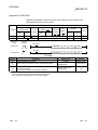
(2) Usable Thermocouples and Measured Temperature Range
Accuracies
The usable thermocouples and measured temperature range accuracies will be
explained.
Usable
Measured
Thermocouple
Temperature Range
Type
1
Conversion Accuracy
(At operating ambient temperature
25 5 )
Temperature Characteristic
(Per operating ambient temperature
variation of 1 )
Max. Temperature
Error at Ambient
Temperature 55
——— 3
——— 3
——— 3
0 to 600
B
2
600 to 800
4.0
2
800 to 1700
1700 to 1820
R
4.0
2
300 to 1600
S
K
4.0
2
300 to 1600
13.5
3
——— 3
——— 3
——— 3
14.0
——— 3
——— 3
13.5
——— 3
-270 to -200
——— 3
——— 3
——— 3
-200 to 0
2
0 to 200
2
2.0
8.25
0.25
1.5
2
-270 to -200
-200 to 200
2
200 to 900
2
7.75
2.0
——— 3
——— 3
8.25
——— 3
——— 3
——— 3
——— 3
1.5
5.25
0.15
900 to 1000
2.0
——— 3
——— 3
5.75
——— 3
-210 to -40
——— 3
——— 3
——— 3
-40 to 200
2
200 to 750
2
J
0.15
5.75
2.0
3
———
-200 to 0
2
0 to 350
2
2.0
3
———
-200 to 0
2
0 to 200
2
——— 3
——— 3
4.5
4.0
3
——— 3
——— 3
——— 3
———
——— 3
-270 to -200
——— 3
0.1
1.5
350 to 400
3
———
——— 3
-270 to -200
0 to 1250
5.25
1.5
750 to 1200
N
14.0
1600 to 1760
0 to 1200
T
——— 3
0.4
3.5
1200 to 1370
E
——— 3
———
——— 3
2
0 to 300
3
———
-50 to 0
——— 3
0.4
3.5
1600 to 1760
13.5
3
———
——— 3
2
0 to 300
3
———
-50 to 0
14.0
0.4
3.5
8.75
2.5
2
8.25
0.25
2.0
8.75
2.5
1250 to 1300
3
———
———
3
——— 3
1: If a value entered from the thermocouple is outside the measured temperature range given in the table, it is handled as the
maximum/minimum value of the measured temperature range.
2: The accuracies only in the temperature ranges of Class 1 to 3 (shaded areas) in JIS C1602-1995 apply.
3: Temperature measurement can be made, but accuracy is not guaranteed.
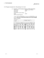
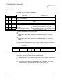
(3) Micro voltage input range and accuracies
The micro voltage input range and accuracies will be explained.
Input Type
Micro voltage input
3-5
Measurable Voltage Range
-100 to 100mV
(At 25
5
Conversion Accuracy
operating ambient temperature)
(At 0 to 55
0.2mV
operating ambient temperature)
0.8mV
3-5
3 SPECIFICATIONS
MELSEC-Q
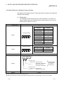
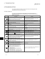
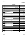
3.2 Function List
The following table lists the Q64TD/Q64TDV-GH functions.
Item
Description
This function allows temperature data to be imported by connecting a
Temperature conversion thermocouple.
function
Temperature data are 16-bit signed binary (-2700 to 18200) and stored into
buffer memory.
Micro voltage
This function converts a -100mV to +100mV micro voltage into a 16-bit,
conversion function
signed binary (-25000 to 25000) and stores it into the buffer memory.
(Q64TDV-GH only)
This function specifies whether temperature/micro voltage conversion is
enabled or disabled on each channel.
Conversion
Setting temperature/micro voltage conversion enable/disable reduces the
enable/disable function
processing time of unused channels. In addition, it prevents unnecessary
disconnection detection of unused channels.
Disconnection detection This function detects the disconnection of the connected thermocouple/micro
function
voltage signal cable on each channel.
Input type selection
This function sets the input type per channel.
function
This function outputs a warning if a temperature/micro voltage falls outside the
Warning output function
user-set temperature/micro voltage input range.
(1) Sampling processing
A temperature input value is converted into a temperature one by one on
Temperature conversion
each channel and a digital output value is output after every conversion.
system (Q64TD)
(2) Averaging processing
A temperature conversion value is averaged in terms of count or time on each
channel and a digital average value is output.
(1) Sampling processing
A temperature/micro voltage input value is converted one by one on each
Temperature/micro
channel and a digital output value is output after every conversion.
voltage conversion
(2) Averaging processing
system
A temperature input value/micro voltage conversion value is averaged in
(Q64TDV-GH)
terms of count or time on each channel and a digital average value is
output.
This function can convert a measured temperature value/micro voltage
Scaling function
conversion value into a preset range ratio (%) and import it into buffer
memory.
This function determines whether cold junction temperature compensation is
made or not using the Pt100 attached to the terminals.
Pt100 cold junction
Use this function when you want to measure temperatures at so high
temperature
accuracy that the cold junction temperature compensation accuracy ( 1 ) of
compensation yes/no
the Pt100 cannot be ignored as an error.
setting function
The cold junction temperature compensation accuracy can be improved by
disabling the cold junction temperature compensation of the Pt100 and
providing a precision ice bath externally.
Offset/gain setting
This function compensates for an error of a measured temperature value or
function
changes the conversion characteristic of a micro voltage conversion value.
Online module change A module change is made without the system being stopped.
3-6
Refer To
Section 3.4.7
—
Section 3.4.3
Section 3.4.6
Section 3.4.14
Section 4.5
Section 3.4.13
Section 3.4.18
Section 3.2.2
Section 3.2.3
Section 3.4.15
Section 3.4.16
Section 3.4.17
Section 4.7
Section 3.4.19
Section 4.6
Chapter 7
3-6
3 SPECIFICATIONS
MELSEC-Q
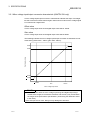
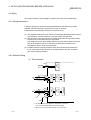
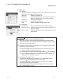
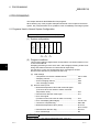
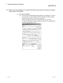
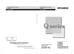
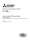
3.2.1 Micro voltage input/output conversion characteristic (Q64TDV-GH only)
A micro voltage input/output conversion characteristic indicates the slope of a straight
line that connects an offset value and gain value when an external micro voltage signal
is converted into a digital value.
Offset value
A micro voltage input value whose digital output value will be -25000.
Gain value
A micro voltage input value whose digital output value will be 25000.
The following indicates the micro voltage input/output conversion characteristic as set
at the factory (offset value: -100mV, gain value: 100mV).
30000
Digital output value
25000
0
25000
30000
100mV
0mV
100mV
Micro voltage input value
POINT
(1) Use the module within the micro voltage input range and digital output range.
Outside those ranges, the maximum resolution and accuracy may not fall within
the ranges of the performance specifications. (Avoid using the dotted line areas
in the chart.)
(2) Do not input ±5V or more. Doing so may damage the elements.
3-7
3-7
3 SPECIFICATIONS
MELSEC-Q
3.2.2 Temperature conversion system (Q64TD)
There are two temperature conversion systems, sampling processing and averaging
processing.
(1) Sampling processing
A temperature input value is converted into a digital value successively and the
digital output value is stored into the buffer memory.
Sampling processing time varies with the number of used channels (number of
channels set to enable temperature conversion).
(Processing time) = (number of used channels)
(40ms)
[Example]
Sampling time is 120ms when three channels, channels 1, 2 and 4, are enabled for
conversion.
3 channels 40ms = 120ms
(2) Averaging processing
The temperatures of the channels specified for averaging processing are
converted by the preset count or for the preset period of time, the sum of the
resultant values except the maximum and minimum values is averaged, and the
result is stored into the buffer memory.
(a) Time averaging processing
The processing count within the preset time varies with the number of used
channels (number of channels set to enable temperature conversion).
(Processing count) =
(preset time)
(number of used channels)
(40ms)
[Example]
The sampling count is 4.75 when four channels, channels 1, 2, 3 and 4, are
enabled for conversion and the preset time is 760ms.
760ms ÷ (4 channels 40ms) = 4.75
Since the fractional portion of an indivisible value is dropped, the sampling
count is 4 times.
(b) Count averaging processing
The time taken to store a count-averaged value into buffer memory varies
with the number of used channels (number of channels set to enable
temperature conversion).
(Processing time) = (preset count)
(number of used channels)
(40ms)
[Example]
An average value is output ever 320ms when two channels, channels 3 and 4,
are enabled for conversion and the preset count is 4.
4 times (2 channels 40ms) = 320ms
3-8
3-8
3 SPECIFICATIONS
MELSEC-Q
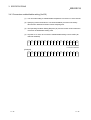
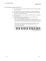
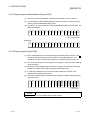
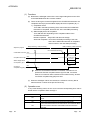
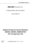
3.2.3 Temperature/micro voltage conversion system (Q64TDV-GH)
Temperature/micro voltage conversion can either be made by sampling processing or
averaging processing.
(1) Sampling processing
A temperature/micro voltage input value is converted successively and a digital
output value is stored into the buffer memory.
The conversion speed changes depending on the number of channels used
(number of channels set for conversion enable).
(Conversion speed) = (sampling period) 3
= {(number of used channels)
(20ms)}
3
[Example] When 2 channels are enabled for conversion
(Conversion speed) = (sampling period) 3
= (20ms 2 channels) 3
= 120ms
Input 1)
Conversion processing
CH1
CH2
Input 2)
CH1
CH2
CH1
CH2
CH1
Buffer memory
CH2
CH1
Input 1)
CH2
Input 2)
Conversion speed
Conversion speed
(2) Averaging processing
The input value of the channel specified for averaging processing is converted by
the preset number of times or for the preset period of time, the sum of the
resultant values except the maximum and minimum values is averaged, and the
average value is stored into the buffer memory.
(a) Time averaging processing
The number of processings performed within the preset time changes
depending on the number of channels used (number of channels set for
conversion enable).
(preset time)
(Processing count) =
(number of used channels) (40ms)
[Example]
When four channels, channels 1, 2, 3 and 4, are enabled for conversion
and the preset time is 760ms, the sampling count is 4.75.
760ms ÷ (4 channels ( 40ms) = 4.75
If the result cannot be divided, its fractional portion is rounded down and
the sampling count is 4 times.
(b) Count averaging processing
The time when the count-based average value is stored into the buffer
memory changes depending on the number of channels used (number of
channels set for conversion enable).
(Processing time) = (preset count)
(number of used channels)
(40ms)
[Example]
When two channels, channels 3 and 4, are enabled for conversion and the
preset count is 4, the average value is output per 320ms.
4 times (2 channels 40ms) = 320ms
3-9
3-9
3 SPECIFICATIONS
MELSEC-Q
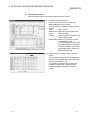
3.3 I/O Signals Transferred to/from PLC CPU
This section describes the I/O signal assignment and signal functions.
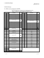
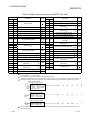
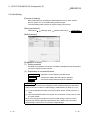
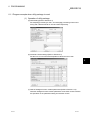
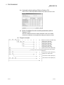
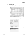
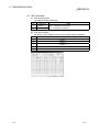
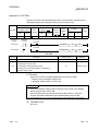
3.3.1 I/O signal list
The following are the I/O signals of the Q64TD/Q64TDV-GH.
The I/O numbers (X/Y) given in this chapter and later assume that the first I/O number
of the Q64TD is set to 0.
Input Signal
(Signal Direction: PLC CPU
Device No.
Q64TD/Q64TDV-GH)
Signal name
Output Signal
(Signal Direction: PLC CPU
Device No.
Q64TD/Q64TDV-GH)
Signal name
X0
Module Ready
Y0
Reserved
X1
CH1 Offset/Gain Setting Status Signal
Y1
CH1 Offset Setting Request
X2
CH2 Offset/Gain Setting Status Signal
Y2
CH1 Gain Setting Request
X3
CH3 Offset/Gain Setting Status Signal
Y3
CH2 Offset Setting Request
X4
CH4 Offset/Gain Setting Status Signal
Y4
CH2 Gain Setting Request
X5
Y5
CH3 Offset Setting Request
X6
Y6
CH3 Gain Setting Request
Y7
CH4 Offset Setting Request
X7
Reserved
X8
Y8
CH4 Gain Setting Request
X9
Operating Condition Setting Completion Signal
Y9
Operating Condition Setting Request
XA
Offset/Gain Setting Mode Status Flag
YA
User Range Write Request
XB
Reserved
YB
XC
Disconnection Detection Flag
YC
XD
Warning Output Signal
YD
XE
Conversion Completion Flag
YE
XF
Error Flag
YF
Reserved
Error Clear Request
POINT
The reserved signals marked are used by the system and are unavailable for the
user. Should they be turned on/off in a sequence program, we cannot guarantee
the functions of the Q64TD/Q64TDV-GH.
3 - 10
3 - 10
3 SPECIFICATIONS
MELSEC-Q
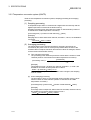
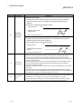
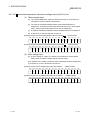
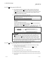
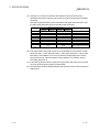
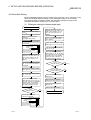
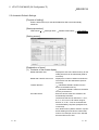
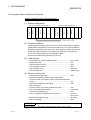
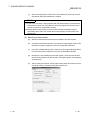
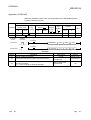
3.3.2 I/O signal details
The following are details of the Q64TD/Q64TDV-GH I/O signals.
(1) Input signals
Device No.
X0
Signal Name
Description
(1) If the module is in the normal mode at power-on or resetting of the PLC CPU, this signal turns
on to start conversion processing as soon as it gets ready for conversion.
(2) When this signal (X0) is off in the normal mode, conversion processing is not performed. In the
offset/gain setting mode, conversion processing is performed if this signal (X0) is off.
(3) This signal (X0) turns off when:
• The module is in the offset/gain setting mode;
• The Q64TD/Q64TDV-GH is in a watchdog timer error 1; or
• The module can be changed during online module change
Module Ready
(1) This signal is used as an interlock condition to turn on/off the CH Offset Setting Request (Y1,
Y3, Y5, Y7)/CH Gain Setting Request (Y2, Y4, Y6, Y8) when offset/gain setting is made.
(2) When the CH Offset Setting Request (Y1, Y3, Y5, Y7) or CH Gain Setting Request (Y2,
Y4, Y6, Y8) is turned from ON to OFF in the offset/gain setting mode, this signal (X1 to 4)
corresponding to the user range setting, conversion-enabled channel turns on.
X1
X2
X3
X4
CH Offset/Gain
Setting Status Signal
CH Offset/Gain Setting
Status Signal (X1 to 4)
CH Offset Setting
Request (Y1, Y3, Y5, Y7)
CH Offset/Gain Setting
Status Signal (X1 to 4)
CH Gain Setting Request
(Y2, Y4, Y6, Y8)
X9
(1) This signal is used as an interlock condition to turn on/off the Operating Condition Setting
Request (Y9) when the "Conversion enable/disable setting", "CH time/count averaging
setting", "Averaging processing specification", "Warning output enable/disable setting", "Scaling
range upper/lower limit value", "CH scaling width upper/lower limit value" or "CH warning
output upper/lower limit value" is changed.
(2) Conversion processing is not performed when this signal (X9) is off.
(3) This signal (X9) turns off when:
Operating Condition
• The Module Ready (X0) is off in the normal mode; or
Setting Completion
• The Operating Condition Setting Request (Y9) is on.
Signal
Operating Condition Setting
Completion Signal (X9)
Operating Condition Setting
Request (Y9)
Conversion Completion Flag
(XE)
1 Occurs if program operation is not completed within the intended time due to a
hardware fault of the Q64TD/Q64TDV-GH. The RUN LED of the Q64TD/Q64TDVGH goes off when a watchdog timer error occurs.
3 - 11
3 - 11
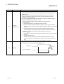
3 SPECIFICATIONS
Device No.
MELSEC-Q
Signal Name
Description
[In offset/gain setting mode]
(1) This signal is used as an interlock condition to turn ON/OFF the User range write
request (YA) when the value at completion of offset/gain setting adjustment is
registered.
(2) See Section 4.6 regarding the offset/gain settings.
Module ready (X0)
OFF
Offset/gain setting mode
status flag (XA)
Offset/Gain
XA
Setting Mode
Status Flag
User range write request (YA)
[In normal mode]
(1) This signal is used as an interlock condition to turn ON/OFF the User range write
request (YA) when the user range is restored.
(2) Refer to Chapter 7 for the user range restoration.
Module ready (X0)
ON
Offset/gain setting mode status
flag (XA)
User range write request (YA)
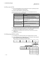
XC
XD
3 - 12
Disconnection
Detection Flag
(1) This signal (XC) is turned on by the thermocouple input circuit of the channel enabled for conversion
when any of the input signal lines including the thermocouple/micro voltage signal cable is
disconnected. At the same time, the Conversion Completion Signal (XE) turns off, and the
conversion update of the disconnection-detected channel stops but the conversion of the channel
not disconnected continues.
(2) When this signal (XC) has turned on, the measured temperature value/micro voltage conversion
value is held at the value immediately before disconnection detection, and the Conversion
Completion Flag (XE) is turned off.
(3) Remove the cause of disconnection and then turn on the Error Clear Request (YF) to turn off this
signal (XC).
(4) When disconnection is recovered, updating of the measured temperature value/micro voltage
conversion value is resumed regardless of whether this signal (XC) was reset or not, and after the
first updating, the Conversion Completion Flag (XE) turns on again.
Warning Output
Signal
(1) This signal turns on when the measured temperature value/micro voltage conversion value has
fallen out of the temperature range set in the warning output upper/lower limit values (buffer memory
addresses 86 to 101: Un\G86 to 101) on any of the channels enabled for conversion.
(2) This signal turns off automatically as soon as the measured temperature value/micro voltage
conversion value returned to within the ranges on all channels enabled for conversion.
3 - 12
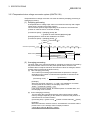
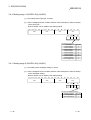
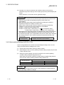
3 SPECIFICATIONS
Device No.
XE
MELSEC-Q
Signal Name
Conversion
Completion Flag
Description
(1) This signal (XE) turns on when the measured temperature value/micro voltage conversion
value of all channels enabled for conversion are stored into buffer memory after power-on or
hardware reset.
(2) When averaging processing is performed, this signal also turns on when the measured
temperature value/micro voltage conversion value are stored into buffer memory after
completion of averaging processing.
(3) This signal (XE) varies as described below depending on whether the Operation Condition
Setting Completed Signal (X9) has turned on or off.
• When the Operation Condition Setting Completed Signal (X9) has turned on
(stop
conversion)
1) Temperature conversions of the enabled channels are started.
2) After the measured temperature value/micro voltage conversion value are stored into
buffer memory, the Conversion completion flags (buffer memory address 10: Un\G10) are
turned on.
3) This signal (XE) is turned on after the measured temperature value/micro voltage
conversion value of all channels enabled for conversion are stored into buffer memory.
• When the Operation Condition Setting Completed Signal (X9) has turned off
(conversion
stop)
1) The Conversion completion flags (buffer memory address 10: Un\G10) of all channels are
turned off.
2) This signal (XE) is turned off.
Note that if conversion is stopped, the measured temperature value/micro voltage
conversion value stored in buffer memory are held at the data immediately before the
stop.
(4) This signal (XE) does not turn on when all channels are disabled for conversion.
(1) This signal (XF) turns on when an error occurs.
(2) To clear the error code, turn on the Error Clear Request (YF).
Error flag (XF)
XF
Error Flag
Error Clear Request (YF)
Error code is read during this period.
3 - 13
3 - 13
3 SPECIFICATIONS
MELSEC-Q
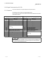
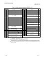
(2) Output signals
Device No.
Signal name
Description
(1) This signal is made valid in the offset/gain setting mode.
(2) This signal corrects the measured temperature value/micro voltage conversion
Y1
value to be an offset value when it is on.
Y3
CH
Y5
Setting Request
Offset
Y7
(3) When this signal turns on while the Gain Setting Request on the same channel is on
or they turn on simultaneously, an error will occur and the operation in (2) not
performed.
(4) For the on/off timing, refer to the field of the CH
Offset/Gain Setting Status Signal
(X1 to 4).
(1) This signal is made valid in the offset/gain setting mode.
(2) This signal corrects the measured temperature value/micro voltage conversion
Y2
value to be a gain set value when it is on.
Y4
CH
Y6
Request
Gain Setting (3) When this signal turns on while the Offset Setting Request on the same channel is
Y8
on or they turn on simultaneously, an error will occur and the operation in (2) not
performed.
(4) For the on/off timing, refer to the field of the CH
Offset/Gain Setting Status Signal
(X1 to 4).
(1) This signal is turned on when the "Conversion enable/disable setting", "CH
time/count averaging setting", "Averaging processing specification", "Warning output
enable/disable setting", "CH
Y9
scaling range upper/lower limit value", "CH
Operating
scaling width upper/lower limit value", "CH
Condition Setting
or "Mode switching setting" is made valid.
Request
warning output upper/lower limit value"
(2) When this signal turns on, the Disconnection Detection Flag (XC) and Warning
Output Signal (XD) turn off.
(3) For the on/off timing, refer to the field of the Operation Condition Setting Completed
Signal (X9).
[In offset/gain setting mode]
(1) This turns ON when the value for the adjusted offset/gain settings are registered in
2
E PROM.
YA
User Range Write
Request
(2) See the XA column for ON/OFF timing.
See Section 4.6 for offset/gain settings.
[In normal mode]
(1) This signal turns ON when the user range is restored.
(2) Refer to the field of XA for the ON/OFF timing.
Refer to Chapter 7 for user range restoration.
(1) This signal is turned on when the Error Flag (XF) and Disconnection Detection Flag
YF
Error Clear
Request
(XC) are cleared.
However, the set value error of the intelligent function module switch setting cannot
be cleared. Correct the set value.
(2) For the on/off timing, refer to the field of the Error Flag (XF).
3 - 14
3 - 14
3 SPECIFICATIONS
MELSEC-Q
POINT
When the User range write request (YA) is turned ON in the normal mode with
conversion enabled, the Q64TD/Q64TDV-GH restores the user range.
Offset/gain setting mode status flag
(XA)
User range write request (YA)
During restoration
User range restoration processing
Restoration
completed
Conversion completion flag
(Buffer memory address 10: Un\G10)
Measured temperature value/micro
voltage value
(Buffer memory addresses 11 to 14:
Un\G11 to 14)
During user range restoration: Conversion stop, Conversion completion flag
(buffer memory addresses 10: Un\G10) OFF,
measured temperature value/micro voltage value
held as previously.
After user range restoration: Conversion resumed (when user range setting is
used, conversion is resumed at the restored
offset/gain setting value.)
3 - 15
3 - 15
3 SPECIFICATIONS
MELSEC-Q
3.4 Buffer Memory
3.4.1 Buffer memory assignment (Q64TD)
This section describes the assignment of the Q64TD buffer memory.
Table 3.1 Buffer memory assignment (Q64TD) (1/2)
Addresses
Description
R/W
0
Conversion enable/disable setting
R/W
1
CH1 time/count averaging setting
Hex.
Dec.
01 H
02 H
1
Addresses
1
Description
R/W
64
CH2 scaling range lower limit value
R/W
3
41 H
65
CH2 scaling range upper limit value
R/W
3
42 H
66
CH3 scaling range lower limit value
R/W
3
Hex.
Dec.
3
40 H
R/W
3
03 H
2
CH2 time/count averaging setting
R/W
3
04 H
3
CH3 time/count averaging setting
R/W
3
43 H
67
CH3 scaling range upper limit value
R/W
3
R/W
3
44 H
68
CH4 scaling range lower limit value
R/W
3
45 H
69
CH4 scaling range upper limit value
R/W
3
46 H
70
to
to
05 H
4
06 H
5
to
to
08 H
8
09 H
9
Averaging processing specification
4D H
77
0A H
10
Conversion completion flag
R
4E H
78
CH1 scaling width lower limit value
R/W
3
0B H
11
CH1 measured temperature value
R
4F H
79
CH1 scaling width upper limit value
R/W
3
0C H
12
CH2 measured temperature value
R
50 H
80
CH2 scaling width lower limit value
R/W
3
0D H
13
CH3 measured temperature value
R
51 H
81
CH2 scaling width upper limit value
R/W
3
0E H
14
CH4 measured temperature value
R
52 H
82
CH3 scaling width lower limit value
R/W
3
0F H
15
53 H
83
CH3 scaling width upper limit value
R/W
3
to
to
54 H
84
CH4 scaling width lower limit value
R/W
3
12 H
18
55 H
85
CH4 scaling width upper limit value
R/W
3
13 H
19
Error code
R
56 H
86
R/W
3
14 H
20
Setting range
R
57 H
87
R/W
3
15 H
21
58 H
88
R/W
3
to
to
59 H
89
R/W
3
2E H
46
5A H
90
R/W
3
2F H
47
Warning output enable/disable setting
5B H
91
R/W
3
30 H
48
Warning output flag
R
5C H
92
R/W
3
31 H
49
Disconnection detection flag
R
5D H
93
R/W
3
32 H
50
CH1 scaling value
R
5E H
94
R/W
3
33 H
51
CH2 scaling value
R
5F H
95
R/W
3
34 H
52
CH3 scaling value
R
60 H
96
R/W
3
35 H
53
CH4 scaling value
R
61 H
97
R/W
3
36 H
54
to
to
3D H
61
3E H
62
CH1 scaling range lower limit value
R/W
3
3F H
63
CH1 scaling range upper limit value
R/W
3
3 - 16
CH4 time/count averaging setting
System area
System area
System area
System area
2
R/W
3
2
2
R/W
3
System area
2
CH1 warning output lower lower limit
value
CH1 warning output lower upper limit
value
CH1 warning output upper lower limit
value
CH1 warning output upper upper limit
value
CH2 warning output lower lower limit
value
CH2 warning output lower upper limit
value
CH2 warning output upper lower limit
value
CH2 warning output upper upper limit
value
CH3 warning output lower lower limit
value
CH3 warning output lower upper limit
value
CH3 warning output upper lower limit
value
CH3 warning output upper upper limit
value
2
3 - 16
3 SPECIFICATIONS
MELSEC-Q
Table 3.1 Buffer memory assignment (Q64TD) (2/2)
Addresses
Hex.
Dec.
62 H
98
1
R/W
CH4 warning output lower lower limit value
R/W
3
A9 H
169
CH2 factory default gain value
AA H
170
CH2 user range settings offset value
63 H
99
CH4 warning output lower upper limit value R/W
3
64 H
100
CH4 warning output upper lower limit value R/W
3
CH4 warning output upper upper limit value R/W
3
65 H
101
66 H
102
to
to
75 H
117
76 H
118
Addresses
Description
System area
2
CH1 offset temperature set value
Hex.
Dec.
A8 H
168
AB H
171
AC H
172
AD H
173
AE H
174
AF H
175
R/W
3
B0 H
B1 H
77 H
119
CH1 gain temperature set value
R/W
3
78 H
120
CH2 offset temperature set value
R/W
3
R/W
Description
4
CH2 factory default offset value
4
CH2 user range settings offset value
CH2 user range settings gain value
4
176
CH3 factory default offset value
4
177
CH3 factory default gain value
CH2 gain temperature set value
R/W
B2 H
178
CH3 user range settings offset value
122
CH3 offset temperature set value
R/W
3
B3 H
179
CH3 user range settings gain value
B4 H
180
B5 H
181
CH3 gain temperature set value
R/W
124
CH4 offset temperature set value
R/W
3
7D H
125
CH4 gain temperature set value
R/W
3
7E H
126
to
to
9D H
System area
2
157
9E H
158
9F H
159
Mode switching setting
4
160
A1 H
161
CH1 factory default gain value
A2 H
162
CH1 user range settings offset value
163
A4 H
164
A5 H
165
A6 H
166
A7 H
167
183
B8 H
184
4
4
4
CH1 user range settings gain value
CH1 user range settings offset value
4
(L)
(H)
CH1 user range settings gain value
4
(L)
(H)
185
4
R/W
(L)
(L)
(H)
4
CH4 factory default offset value
CH4 factory default gain value
186
CH4 user range settings offset value
187
CH4 user range settings gain value
R/W
BC
H
188
R/W
BD H
189
R/W
BE H
190
R/W
BF H
191
C0 H
192
to
to
CH4 user range settings offset value
R/W
4
R/W
(L)
(H)
CH4 user range settings gain value
4
(L)
(H)
System area
R/W
R/W
4
4
R/W
R/W
4
BB H
R/W
R/W
(H)
CH3 user range settings gain value
R/W
R/W
4
4
CH3 user range settings offset value
R/W
R/W
4
BA H
R/W
CH1 factory default offset value
A3 H
182
B9 H
H
A0
B6 H
B7 H
(L)
4
121
123
R/W
(L)
(H)
79 H
7B H
R/W
(H)
7A H
7C H
R/W
4
4
3
3
R/W
4
CH2 user range settings gain value
1
R/W
R/W
2
R/W
1 Indicates whether read/write is enabled or disabled from sequence program.
R : Read enabled
W : Write enabled
2 These addresses are used by the system and are unavailable for the user.
Should data be written to any of those addresses using a sequence program, we cannot guarantee the functions of the Q64TD.
3 Data must be written to buffer memory under the interlock conditions (buffer memory write conditions) of the following I/O signals.
4 This area is related with the user range save/restore function and allows users to re-set the offset/gain values easily in the case of
online module change.
3 - 17
3 - 17
3 SPECIFICATIONS
MELSEC-Q
• Operation condition setting
Buffer memory write conditions
Setting
request
switch
Operation Operation condition
condition
setting completed
setting request signal
• Offset setting
Buffer memory write conditions
Offset setting Offset setting Offset/gain setting
completed signal
switch
request
• Gain setting
Buffer memory write conditions
Gain setting Gain setting Offset/gain setting
completed signal
switch
request
3 - 18
3 - 18
3 SPECIFICATIONS
MELSEC-Q
3.4.2 Buffer memory assignment (Q64TDV-GH)
The assignment of the Q64TDV-GH buffer memory will be explained.
Table 3.2 Buffer memory assignment (Q64TDV-GH) (1/2)
Addresses
Description
R/W
R/W
R/W
Hex.
Dec.
00 H
0
Conversion enable/disable setting
01 H
1
CH1 time/count averaging setting
1
3
46 H
70
3
to
to
4D H
77
4E H
4F H
78
79
CH1 scaling width lower limit value
CH1 scaling width upper limit value
R/W
R/W
3
50 H
80
CH2 scaling width lower limit value
R/W
3
51 H
81
CH2 scaling width upper limit value
R/W
3
52 H
82
CH3 scaling width lower limit value
R/W
3
53 H
83
CH3 scaling width upper limit value
R/W
3
3
2
CH2 time/count averaging setting
R/W
03 H
3
CH3 time/count averaging setting
R/W
R/W
3
3
04 H
4
05 H
to
5
to
08 H
8
09 H
9
Averaging processing specification
0A H
10
0B H
11
0C H
12
0D H
13
0E H
14
Conversion completion flag
CH1 measured temperature value/micro
voltage conversion value
CH2 measured temperature value/micro
voltage conversion value
CH3 measured temperature value/micro
voltage conversion value
CH4 measured temperature value/micro
voltage conversion value
0F H
to
12 H
13 H
14 H
15 H
16 H
to
2E H
15
to
18
19
20
21
22
to
46
2F H
47
Warning output enable/disable setting
30 H
31 H
32 H
33 H
34 H
35 H
36 H
to
3D H
3E H
3F H
40 H
41 H
42 H
43 H
44 H
48
49
50
51
52
53
54
to
61
62
63
64
65
66
67
68
Warning output flag
Disconnection detection flag
CH1 scaling value
CH2 scaling value
CH3 scaling value
CH4 scaling value
CH1 scaling range lower limit value
CH1 scaling range upper limit value
CH2 scaling range lower limit value
CH2 scaling range upper limit value
CH3 scaling range lower limit value
CH3 scaling range upper limit value
CH4 scaling range lower limit value
R/W
R/W
R/W
R/W
R/W
R/W
R/W
3
45 H
69
CH4 scaling range upper limit value
R/W
3
3 - 19
System area
2
System area
3
System area
2
3
R
54
H
84
CH4 scaling width lower limit value
R/W
R
55 H
85
CH4 scaling width upper limit value
R/W
3
R
56 H
86
R/W
3
R
57 H
87
R/W
3
R
58 H
88
R/W
3
59 H
89
R/W
3
5A H
90
R/W
3
5B H
91
R/W
3
5C H
92
R/W
3
5D H
93
R/W
3
5E H
94
R/W
3
5F H
95
R/W
3
60 H
96
R/W
3
61 H
97
CH3 warning output upper upper limit
value
R/W
3
62 H
98
CH4 warning output lower lower limit
value
R/W
3
63 H
99
CH4 warning output lower upper limit
value
R/W
3
64 H
100
CH4 warning output upper lower limit
value
R/W
3
65 H
101
CH4 warning output upper upper limit
value
R/W
3
2
Error code
Setting range 1
Setting range 2
System area
R/W
1
Dec.
02 H
System area
R/W
Description
Hex.
3
CH4 time/count averaging setting
Addresses
R
R
R
2
R/W
3
R
R
R
R
R
R
2
3
3
3
3
3
CH1 warning output lower lower limit
value
CH1 warning output lower upper limit
value
CH1 warning output upper lower limit
value
CH1 warning output upper upper limit
value
CH2 warning output lower lower limit
value
CH2 warning output lower upper limit
value
CH2 warning output upper lower limit
value
CH2 warning output upper upper limit
value
CH3 warning output lower lower limit
value
CH3 warning output lower upper limit
value
CH3 warning output upper lower limit
value
3
3 - 19
3 SPECIFICATIONS
MELSEC-Q
Table 3.2 Buffer memory assignment (Q64TDV-GH) (2/2)
Addresses
Hex.
Dec.
66 H
102
R/W
Description
System area
1
2
to
to
75 H
117
76 H
118
CH1 offset setting value
R/W
77 H
119
CH1 gain setting value
Addresses
Hex.
Dec.
AA H
170
AB H
171
AC H
172
3
AD H
173
R/W
3
AE H
174
AF H
175
B0 H
176
R/W
Description
CH2 user range settings gain value
CH2 user range settings thermal EMF
offset value 4
(H)
R/W
CH2 user range settings thermal EMF (L)
gain value 4
(H)
R/W
120
CH2 offset setting value
R/W
79 H
121
CH2 gain setting value
R/W
3
B1 H
177
CH3 factory default gain value
B2 H
178
CH3 user range settings offset value
122
CH3 offset setting value
R/W
7B H
123
CH3 gain setting value
R/W
3
7C H
124
7D H
125
7E H
126
to
to
9D H
157
9E H
158
9F H
159
CH4 offset setting value
CH4 gain setting value
System area
Mode switching setting
160
CH1 factory default offset value
A1 H
161
CH1 factory default gain value
R/W
3
R/W
4
4
A2 H
162
CH1 user range settings offset value
A3 H
163
CH1 user range settings gain value
A4 H
164
A5 H
165
A6 H
166
A7 H
167
A8 H
168
169
3
2
A0 H
A9 H
R/W
4
4
181
B6 H
182
B7 H
183
B8 H
184
B9 H
185
R/W
R/W
CH3 user range settings thermal EMF (L)
offset value 4
(H)
R/W
4
CH3 user range settings gain value
(L)
(H)
4
CH4 factory default offset value
CH4 factory default gain value
186
CH4 user range settings offset value
187
CH4 user range settings gain value
R/W
BC H
188
R/W
BD H
189
BE H
190
BF H
191
C0 H
192
to
to
R/W
R/W
4
BB H
R/W
CH2 factory default gain value
180
R/W
4
CH3 user range settings thermal EMF gain
value 4
BA H
CH1 user range settings thermal EMF (L)
gain value 4
(H)
4
B4 H
B5 H
R/W
4
R/W
R/W
4
179
4
CH3 factory default offset value
R/W
CH1 user range settings thermal EMF (L)
offset value 4
(H)
CH2 factory default offset value
B3 H
R/W
(L)
78 H
7A H
R/W
4
3
3
4
CH2 user range settings offset value
R/W
4
R/W
4
R/W
CH4 user range settings thermal EMF (L)
offset value 4
(H)
R/W
CH4 user range settings thermal EMF (L)
gain value 4
(H)
R/W
System area
1
2
R/W
R/W
1 Indicates whether read/write is enabled or disabled from sequence program.
R : Read enabled
W : Write enabled
2 These addresses are used by the system and are unavailable for the user.
Should data be written to any of those addresses using a sequence program, we cannot guarantee the functions of the Q64TDV-GH.
3 Data must be written to buffer memory under the interlock conditions (buffer memory write conditions) of the following I/O signals.
• Operating condition setting
Buffer memory write conditions
Setting
request
switch
Operating condition
Operating
setting completion
condition
setting request signal
• Offset setting
Buffer memory write conditions
Offset setting Offset setting Offset/gain setting
switch
request
completion signal
• Gain setting
Buffer memory write conditions
Gain setting Gain setting Offset/gain setting
switch
request completion signal
4 This area is related with the user range save/restore function and allows users to re-set the offset/gain values easily in the case of
online module change.
3 - 20
3 - 20
3 SPECIFICATIONS
MELSEC-Q
3.4.3 Conversion enable/disable setting (Un\G0)
(1) You can make setting to enable/disable temperature conversion on each channel.
(2) Specifying unused channels as "conversion disabled" prevents unnecessary
disconnection detection and also reduces sampling time.
(3) The Operating Condition Setting Request (Y9) must be turned on/off to make the
conversion enable/disable setting valid.
(4) At power-on or reset, the conversion enable/disable setting is set to 000FH (all
channels disabled).
b15 b14 b13 b12 b11 b10
0
0
0
0
0
0
b9
b8
b7
b6
b5
b4
0
0
0
0
0
0
b3
b2
b1
b0
CH4 CH3 CH2 CH1
0: Conversion enabled
1: Conversion disabled
[Example]
b15 b14 b13 b12 b11 b10
0
0
0
0
0
0
b9
b8
b7
b6
b5
b4
b3
b2
b1
b0
0
0
0
0
0
0
1
1
0
0
Channels 1 and 2 are conversion enabled.
3 - 21
3 - 21
3 SPECIFICATIONS
3.4.4 CH
MELSEC-Q
time/count averaging setting (Un\G1 to 4)
(1) Set the averaging time or averaging count for each channel when averaging
processing is selected. (buffer memory address 9: Un\G9).
(2) Setting can be made within the following ranges.
Time averaging processing: 160 to 5000ms (Q64TD)
80 to 2500ms (Q64TDV-GH)
Count averaging processing: 4 to 62500 times
If you set any value outside the range, it will result in an error and the previous
setting will not be updated.
(3) This setting will be invalid if sampling is specified in the averaging processing
specification (buffer memory address 9: Un\G9).
(4) At power-on or reset, this area is set to 0000H (averaging time 0/averaging count
0).
(5) The Operating Condition Setting Request (Y9) must be turned on/off to make this
setting valid.
(6) Refer to Section 3.4.5 for details of sampling processing/time averaging
processing/count averaging processing.
3.4.5 Averaging processing specification (Un\G9)
(1) To select sampling or averaging processing, write values to the buffer memory
address 9 (Un\G9).
(2) When you selected averaging processing, choose time averaging or count
averaging.
(3) The default is set to sampling processing for all channels.
b15 b14 b13 b12 b11 b10
0
0
0
0
b9
b8
CH4 CH3 CH2 CH1
b7
b6
b5
b4
0
0
0
0
Setting of channels
1: Averaging processing
0: Sampling processing
b3
b2
b1
b0
CH4 CH3 CH2 CH1
Selection of time/count
1: Time averaging
0: Count averaging
(4) The Operating Condition Setting Request (Y9) must be turned on/off to make this
setting valid.
Example
To specify count averaging for channels 1, time averaging for channels 2 and sampling processing for other
channels, store 0302H (770) into the buffer memory address 9 (Un\G9).
b15 b14 b13 b12 b11 b10
0
0
0
0
0
0
b9
1
b8
1
b7
0
b6
0
b5
0
CH4 CH3 CH2 CH1
0
3 - 22
3
b4
0
b3
0
b2
0
b1
1
b0
0 0302H (770)
CH4 CH3 CH2 CH1
0
2
3 - 22
3 SPECIFICATIONS
MELSEC-Q
3.4.6 Conversion completion flag (Un\G10)
(1) You can check whether the channels specified for conversion enable succeeded
in normal conversion.
(2) You can make check on each channel using the conversion completion flag.
(3) The conversion completion flag is cleared when the Operating Condition Setting
Request (Y9) is turned from ON to OFF.
(4) When disconnection occurs, the conversion completion flag of the corresponding
channel is cleared.
(5) The Conversion Completion Flag (XE) turns on when conversions of all
conversion-enabled channels are completed.
• When conversion enable/disable setting is turned from 1 (disable) to 0 (enable)
After the measured temperature value/micro voltage conversion voltage is stored into the
buffer memory, the conversion completion flag of the corresponding channel is turned to
1.
• When the conversion enable/disable setting is turned from 0 (enable) to 1 (disable)
The conversion completion flag of the corresponding channel is turned to 0.
• When disconnection is detected
The conversion completion flag of the corresponding channel is turned to 0.
b15 b14 b13 b12 b11 b10
0
0
0
0
0
0
b9
b8
b7
b6
b5
b4
0
0
0
0
0
0
b3
b2
b1
b0
CH4 CH3 CH2 CH1
1: Conversion completed
0: During conversion or unused
3 - 23
3 - 23
3 SPECIFICATIONS
3.4.7 CH
MELSEC-Q
measured temperature value/micro voltage value (Un\G11 to 14)
(1) Thermocouple input
(a) The "thermal EMF value" input from the thermocouple is converted into a
"temperature value" to detect a temperature.
(b) The value of the measured temperature to the first decimal place is
multiplied by 10 and the result is stored into buffer memory in 16-bit signed
binary. (The second decimal place and on are rounded down.)
(c) A negative measured temperature value is displayed as two's complement.
(d) At power-on or reset, all channels are set to 0.
[Example 1] At the measured temperature value of 123.025
b15 b14 b13 b12 b11 b10
0
0
0
0
0
1
b8
b7
b6
b5
b4
b3
b2
b1
b0
0
0
1
1
0
0
1
1
1
0
[Example 2] At the measured temperature value of -123.025
b15 b14 b13 b12 b11 b10
1
1
1
1
1
0
..... 1230 is stored.
b9
..... -1230 is stored.
b9
b8
b7
b6
b5
b4
b3
b2
b1
b0
1
1
0
0
1
1
0
0
1
0
(2) Micro voltage input
(a) A micro voltage of -100mV to +100mV is converted into a 16-bit, signed
binary value of -25000 to 25000, and the result is stored.
(b) A negative micro voltage conversion value is displayed as two's complement.
(c) At power-on or reset, all channels are set to 0.
[Example 1] At the micro voltage input value of 51.300mV ..... 12825 is stored.
b15
b14
b13
b12
b11
b10
b9
b8
b7
b6
b5
b4
b3
b2
b1
b0
0
0
1
1
0
0
1
0
0
0
0
1
1
0
0
1
[Example 2] At the micro voltage input value of -51.300mV ..... -12825 is stored.
3 - 24
b15
b14
b13
b12
b11
b10
b9
b8
b7
b6
b5
b4
b3
b2
b1
b0
1
1
0
0
1
1
0
1
1
1
1
0
0
1
1
1
3 - 24
3 SPECIFICATIONS
MELSEC-Q
3.4.8 Error code (Un\G19)
(1) When the Q64TD/Q64TDV-GH has detected a set value or operation procedure
error, the corresponding error code is stored.
(2) The error code is stored as a 16-bit binary value.
(3) When an error occurs, the "ERROR LED" of the Q64TD/Q64TDV-GH is lit.
(4) The following are main checking details.
Timing
Description
• Check on the intelligent function module switch settings of
At start
GX Developer
• Check on averaging processing specification
When Operating Condition Setting
Request (Y9) has turned from ON to • Check on averaging time and averaging count
OFF
• Check on warning output upper/upper limit values
• Check on offset/gain setting
• Check on preset CH offset temperature value/CH gain
When Offset Setting Request (Y1, Y3,
temperature value
Y5, Y7) or Gain Setting Request (Y2,
• Check whether Offset Setting Request (Y1, Y3, Y5, Y7) and
Y4, Y6, Y8) is turned on
Gain Setting Request (Y2, Y4, Y6, Y8) are not turned on at
the same time.
• Check whether the same data was written consecutively or
When User Range Write Request
not.
(YA) has turned from ON to OFF
• Check whether the pass data has been set or not.
• Check whether the same data was written consecutively or
When G.OGSTOR instruction is
not.
• Check whether a different model has been mounted or not by
executed in sequence program
an online module change.
Supported by the module of function version C or later.
(5) When two or more errors occurred, the error code of the error found first is stored
and latter errors are not stored. However, you can confirm the latter errors in the
error history of the detailed module information of GX Developer.
(6) Giving the Error Clear Request (YF) clears the error code and turns off the lit
"ERROR LED".
(7) Clearing the error stores 0.
3.4.9 Setting range (Q64TD) (Un\G20)
(1) The settings of the "thermocouple type" and "offset/gain setting" are stored.
(2) Use the intelligent function module switches of GX Developer to make settings of
the "thermocouple type" and "offset/gain setting".
Refer to Section 4.5 for details of the setting method.
b15 b14 b13 b12 b11 b10
CH4
b9
CH3
b8
b7
b6
b5
b4
b3
CH2
3 - 25
b1
b0
CH1
b3
Set value of offset/gain setting
Offset/Gain Setting Set Value
Factory default
0
User range setting
1
b2
b2
b1
b0
Set value of thermocouple type
Thermocouple Type Set Value
K
0
1
E
2
J
3
T
4
B
5
R
6
S
7
N
3 - 25
3 SPECIFICATIONS
MELSEC-Q
3.4.10 Setting range 1 (Q64TDV-GH) (Un\G20)
(1) The setting of the "input type" is stored.
(2) Use the intelligent function module switches of GX Developer to make the setting
of the "input type".
Refer to Section 4.5 for details of the setting method.
b15 b14 b13 b12 b11 b10
CH4
b9
b8
b7
b6
CH3
b5
b4
b3
b2
CH2
b1
b0
CH1
b3
b2
b1
Set value of input type
Input Type
Thermocouple K
Thermocouple E
Thermocouple J
Thermocouple T
Thermocouple B
Thermocouple R
Thermocouple S
Thermocouple N
Micro voltage input
b0
Set Value
0
1
2
3
4
5
6
7
8
3.4.11 Setting range 2 (Q64TDV-GH) (Un\G21)
(1) The setting of the "offset/gain setting" is stored.
(2) Use the intelligent function module switches of GX Developer to make the setting
of the "offset/gain setting".
Refer to Section 4.5 for details of the setting method.
b15 b14 b13 b12 b11 b10
CH4
b9
CH3
b8
b7
b6
b5
b4
b3
b2
CH2
b1
b0
CH1
b3
b2
b1
0
0
0
b0
Set value of offset/gain setting
Set Value
Offset/Gain Setting
Factory default
0
1
User range setting
3 - 26
3 - 26
3 SPECIFICATIONS
MELSEC-Q
3.4.12 Warning output enable/disable setting (Un\G47)
(1) This area is used to set whether a warning will be output or not per channel.
(2) The Operating Condition Setting Request (Y9) must be turned on/off to make the
warning output enable/disable setting valid.
(3) At power-on or reset, the warning output enable/disable setting is set to 000FH (all
channels disabled).
b15 b14 b13 b12 b11 b10
0
0
0
0
0
0
b9
b8
b7
b6
b5
b4
0
0
0
0
0
0
b3
b2
b1
b0
CH4 CH3 CH2 CH1
0: Warning output enable
1: Warning output disable
[Example]
b15 b14 b13 b12 b11 b10
0
0
0
0
0
0
b9
b8
b7
b6
b5
b4
b3
b2
b1
b0
0
0
0
0
0
0
1
1
0
0
Channels 1 and 2 are warning output enabled.
3.4.13 Warning output flag (Un\G48)
(1) When a temperature/micro voltage detected is outside the range set for the CH
warning output upper/lower limit value (buffer memory addresses 86 to 101:
Un\G86 to 101), the warning output flag of the corresponding channel turns to 1.
(2) You can check whether the warning given is the upper or lower limit value warning
on each channel.
(3) When the measured temperature value/micro voltage conversion value returned
to within the measurement range, the flag is automatically reset.
(4) If a warning is detected on any of the channels enabled for conversion, the
Warning Output Signal (XD) turns on.
0
0
0
0
0
b6
b5
b4
b3
b2
b1
b0
CH1 lower
limit value
0
b7
CH2 lower
limit value
CH1 upper
limit value
0
b8
CH2 upper
limit value
0
b9
CH4 lower
limit value
CH3 upper
limit value
CH3 lower
limit value
b15 b14 b13 b12 b11 b10
CH4 upper
limit value
(5) The warning output flag is cleared when the Operation Condition Setting Request
(Y9) is turned on.
0: Normal
1: Out-of-range
POINT
Refer to Section 3.4.18 for details of the warning output.
3 - 27
3 - 27
3 SPECIFICATIONS
MELSEC-Q
3.4.14 Disconnection detection flag (Un\G49)
(1) The disconnection detection flag of the corresponding channel turns to 1 when the
disconnection of the thermocouple, compensation conductor or micro voltage
signal cable is detected.
(2) Disconnection detection is made on only the channels set for conversion enable.
(3) Disconnection is detected on each channel.
(4) If disconnection is detected on any of the channels enabled for conversion, the
Disconnection Detection Flag (XC) also turns on. At the same time, the
Conversion Completion Signal (XE) turns off, and the conversion update of the
disconnection-detected channel stops but the conversion of the channel not
disconnected continues.
b15 b14 b13 b12 b11 b10
0
0
0
0
0
0
b9
b8
b7
b6
b5
b4
0
0
0
0
0
0
b3
b2
b1
b0
CH4 CH3 CH2 CH1
0: Normal
1: Disconnection
(5) The disconnection detection flag is cleared when the Operation Condition Setting
Request (Y9) or Error Clear Request (YF) is turned on.
Clearing of the disconnection detection flag using the Error Clear Request (YF) is
supported by the module of function version C or later.
(6) The relationships between disconnection detection and conversion enable/disable
setting are indicated below.
Conversion
Enable/Disable Setting
Connection Status
+
Disconnection Detection
Flag
Conversion enable
OFF
Without
disconnection
-
+
With
disconnection
-
+
Without connection
Conversion disable
Conversion enable
ON
Conversion disable
OFF
Conversion enable
ON
Conversion disable
OFF
POINT
• Any channel where no thermocouple, compensation conductor or micro voltage signal
cable is connected must be set to "conversion disable".
Not doing so will turn on the disconnection detection flag.
• The measured temperature value/micro voltage conversion value of the channel whose
disconnection detection turned on is held at the value immediately before disconnection
detection, and the conversion completion flag of the corresponding channel turns off.
If the connection is restored after disconnection detection, the updating of the measured
temperature value/micro voltage conversion value is resumed and the conversion
completion flag turns on again.
• Refer to Section 4.4 for the wiring of the thermocouple, compensation conductor or micro
voltage signal cable.
• Refer to Section 8.2.5 for the troubleshooting of disconnection detection.
3 - 28
3 - 28
3 SPECIFICATIONS
3.4.15 CH
MELSEC-Q
scaling value (Un\G50 to 53)
(1) The measured temperature value/micro voltage conversion value within the
scaling range set for the CH scaling range upper/lower limit values (buffer
memory address 62 to 69: Un\G62 to 69) is scaled to the scaling width set for the
CH scaling width upper/lower limit values (buffer memory address 78 to 85:
Un\G78 to 85) and the result is stored.
(2) The following is how to calculate the scaling value.
Scaling value =
(Scaling width upper limit value - Scaling width lower limit value)
Measured temperature value/
micro voltage conversion value - Scaling range lower limit value
=Scaling width lower limit value
Scaling range upper limit value - Scaling range lower limit value
[Example]
To scale a temperature to a percent
When the CH1 measured temperature value of 360 (measured temperature
value = 3600) is scaled at the following settings,
Scaling range: -100 to 500 (lower limit value = -1000, upper limit value = 5000)
Scaling width: 0 to 100% (lower limit value = 0, upper limit value = 100)
Scaling value=
(100-0)
3600-(-1000)
+0=76.666666
5000-(-1000)
=77[%]
Fractional portion is rounded off.
Stored into buffer memory address 50.
POINT
(1) If the upper limit value is less than the lower limit value in the settings of the CH
scaling range upper/lower limit values (buffer memory address 62 to 69:
Un\G62 to 69) or CH scaling width upper/lower limit values (buffer memory
address 78 to 85: Un\G78 to 85), it will not result in an error and the scaling
value will be output using the above calculation expression to make calculation.
(2) If the temperature/micro voltage measured is outside the range set by the upper
and lower limit values of the scaling range, the value set as the upper or lower
limit value of the scaling width is stored into the buffer memory.
3.4.16 CH
scaling range upper/lower limit values (Un\G62 to 69)
(1) Set the scaling range of the temperature measurement value/micro voltage
conversion value on each channel.
The setting for the measured temperature value is in 0.1 increments.
(2) 0 is set at power-on or reset.
(3) The scaling range that may be set is -32768 to 32767.
(4) Scaling will not be made if the upper limit value and lower limit value are equal.
(5) The Operating Condition Setting Request (Y9) must be turned on/off to make the
setting valid.
3 - 29
3 - 29
3 SPECIFICATIONS
3.4.17 CH
MELSEC-Q
scaling width upper/lower limit values (Un\G78 to 85)
(1) Set the scaling width on each channel.
(2) 0 is set at power-on or reset.
(3) The scaling range that may be set is -32768 to 32767.
(4) Set the upper and lower limit values to 0 when scaling will not be made.
(5) The Operating Condition Setting Request (Y9) must be turned on/off to make the
setting valid.
3.4.18 CH
warning output upper/lower limit values (Un\G86 to 101)
Temperature
(1) Set the warning output range of the measured temperature value/micro voltage
conversion value on each channel.
The setting for the measured temperature value is in 0.1 increments.
(2) The warning output range region can be set in four levels of the warning output
upper upper value, upper lower value, lower upper value and lower lower value.
(3) If the detected temperature value/micro voltage conversion value rises above the
warning output upper upper limit value or falls below the warning output lower
lower limit value to fall within the warning output range region, the warning output
flag (buffer memory address 48: Un\G48) and warning output signal (XD) give the
warnings.
(4) When the temperature value falls below the warning output upper lower limit value
or rises above the warning output lower upper limit value to return to within the
temperature range, "0" is stored into the warning output flag (buffer memory
address 48: Un\G48) bit position corresponding to the channel number.
The Warning Output Signal (XD) turns off only when all channels return to within
the temperature range.
Warning
output
Upper upper
limit value
Upper lower
limit value
Warning output range region
Region outside warning output range
Included
Warning clear
Warning clear
Lower upper
limit value
Lower lower
limit value
Warning output
Time
3 - 30
3 - 30
3 SPECIFICATIONS
MELSEC-Q
(5) At power-on or reset, the minimum and maximum values of the accuracy
guarantee range of the input type set as the input type (set using GX Developer)
are stored.
The upper upper limit value is set to be equal to the upper lower limit value, and
the lower upper limit value equal to the lower lower limit value.
Input type
Lower upper
limit value
Settings at Power-On or Reset
Lower lower
Upper upper
limit value
limit value
Upper lower
limit value
Available Temperature
Range(Accuracy guarantee range)
Thermocouple K
Thermocouple E
-2000
-2000
12000
9000
-2700 to 13700 (-2000 to 12000)
-2700 to 10000 (-2000 to 9000)
Thermocouple J
Thermocouple T
-400
-2000
7500
3500
-2100 to 12000 (-400 to 7500)
-2700 to 4000 (-2000 to 3500)
Thermocouple B
Thermocouple R
6000
0
17000
1600
0 to 18200 (-6000 to 17000)
-500 to 17600 (-0 to 1600)
Thermocouple S
Thermocouple N
0
-2000
1600
12500
-500 to 17600 (-0 to 1600)
-2700 to 13000 (-2000 to 12500)
Micro voltage
input
-2500
25000
-30000 to 30000 (-25000 to 25000)
(6) If the temperature range that may be set is not satisfied or the condition of lower
lower limit value ≤ lower upper limit value < upper lower limit value ≤ upper upper
limit value is not satisfied, an error occurs and the corresponding error code is
stored into the error code area (buffer memory address 19: Un\G19), and the
Error Flag (XF) turns on.
(7) If the lower upper limit value is equal to the upper lower limit value, an error does
not occur and the warning output is made invalid.
(8) The Operating Condition Setting Request (Y9) must be turned on/off to make the
setting valid.
3 - 31
3 - 31
3 SPECIFICATIONS
MELSEC-Q
3.4.19 CH offset/gain temperature value (Q64TD)/CH
(Q64TDV-GH) (Un\G118 to 125)
offset/gain setting value
(1) Offset/gain setting (error compensation) is a function designed to compensate for
the value at any two points (offset value/gain value) within the operating range
when the proper measured temperature value/micro voltage conversion value is
not available at a system start or when the input type is changed.
(2) When the Offset Setting Request/Gin Setting Request (Y1 to 8) is turned on in the
offset/gain setting mode, the measured temperature value/micro voltage
conversion value is corrected to be the set value written to this area. (Setting for
measured temperature value in 0.1 increments)
[Example] To set to 0.3 ..... Store 3.
(3) Error compensation is made by reading the measured temperature value/micro
voltage conversion value of the buffer memory using a sequence program and
monitoring the values on the peripheral device.
(4) The following are the relationships between the measured temperature value/
micro voltage conversion value and offset value/gain value relative to the input
temperature.
(a) Thermocouple input
Gain value
80[
]
Measured temperature
value is corrected to be input
temperature.
79.7
Measured temperature value
-50[
]
0
80[
]
Input temperature
Measured temperature
value is corrected to be input
temperature.
Characteristic before error compensation
Characteristic after error compensation
-49.7
-50[
]
Offset value
(b) Micro voltage input
Gain value
25000
Micro voltage conversion
value is corrected to be
gain setting.
24975
Micro voltage conversion value
75[mV]
0
100[mV]
Micro voltage input value
18723
Micro voltage conversion
value is corrected to be
offset setting.
Characteristic before error compensation
Characteristic after error compensation
18750
Offset value
3 - 32
3 - 32
3 SPECIFICATIONS
MELSEC-Q
(5) At power-on or reset, the minimum and maximum values in the accuracy
guarantee range of the input type set as Input type (set using GX Developer) are
stored.
Refer to Section 3.4.18 for the accuracy guarantee range.
POINT
• High accuracy is ensured for the offset and gain values when the minimum and
maximum values within the operating range are used to make error
compensation.
• Make offset/gain value setting while simultaneously reading the measured
temperature value/micro voltage conversion value.
• Always set the offset and gain values so that they will satisfy the following
conditions. An error will occur if the conditions are not satisfied.
Condition 1: Within the input enabled range
Condition 2: (Gain value) - (offset value) > 0.1 [ ] (for temperature input)
or (Gain value) - (offset value) > 4 [ V] (for micro voltage input)
• By giving the user range write request, the offset and gain values are stored into
2
the E PROM of the Q64TD/Q64TDV-GH and will not be erased at power-off.
• For thermocouple input, error compensation may also be made using a standard
DC voltage generator or like instead of inputting a temperature directly to the
thermocouple.
Power value of standard
DC voltage generator
=
Thermoelectromotive force value of thermocouple used
as offset/gain value relative to input temperature
3.4.20 Mode switching setting (Un\G158 to 159)
Used to change between the normal mode and offset/gain setting mode. You can
change the mode without resetting the PLC CPU.
(1)
Set the value of the mode to which you want to switch.
(2)
After setting the value, turn the operating condition setting request (Y9) from OFF
to ON to shift the mode.
(3)
When the mode is switched, this area is cleared to zero and the operating
condition setting completion flag (X9) turns off.
After making sure that the operating condition setting completion flag (X9) has
turned off, turn off the operating condition setting request (Y9).
Mode to Be Shifted to
Set Value
Buffer memory address 158
Buffer memory address 159
Normal mode
0964H
4144H
Offset/gain setting mode
4144H
0964H
POINT
If the value written is other than the above, mode switching is not performed and
only the operating condition is changed.
3 - 33
3 - 33
3 SPECIFICATIONS
MELSEC-Q
3.4.21 Factory default offset/gain value/User range settings offset/gain value/User range
settings thermal EMF offset/gain value (Un\G160 to 191)
(1)
This area is related with the user range save/restore function and allows users to
re-set the offset/gain values easily in the case of online module change.
(2)
When the offset/gain values of the user range setting are restored, the used data
are stored.
The data are stored (saved) when:
• Initial setting write is performed by the utility;
• The operating condition is set (Y9 turns from OFF to ON 1)
• The offset/gain values are written in the offset/gain setting mode (YA turns from
OFF to ON).
1: The data are not saved when values have been written to the mode
switching setting area (buffer memory addresses 158, 159: Un\G158,
Un\G159).
(3)
When restoring the offset/gain values of the user range setting, set the data
saved here similarly into the corresponding area of the module where the data
will be restored.
(4)
Buffer memory saving recording procedure for online module change
1) Turn the operating condition setting request (Y9) from OFF to ON.
2) Compare the Factory default offset/gain value/User range settings offset/gain
value/User range settings thermal EMF offset/gain value (buffer memory
addresses 160 to 191: Un\G160 to Un\G191) with the range reference values.
Refer to Section 7.4 for the range reference values.
3) If the values are proper, record the Factory default offset/gain value/User
range settings offset/gain value/User range settings thermal EMF offset/gain
value.
(5) Refer to Chapter 7 for details of online module change.
POINT
This area is not used for the offset/gain settings.
For the offset/gain settings, refer to section 4.6.
3 - 34
3 - 34
4 SETUP AND PROCEDURES BEFORE OPERATION
MELSEC-Q
4 SETUP AND PROCEDURES BEFORE OPERATION
4.1 Handling Precautions
(1) Do not drop the module or subject it to heavy impact.
(2) Do not remove the PCB of the module from its case. Doing so may cause the
module to fail.
(3) Be careful not to let foreign particles such as swarf or wire chips enter the module.
They may cause a fire, mechanical failure or malfunction.
(4) The top surface of the module is covered with a protective film to prevent foreign
objects such as wire burrs from entering the module during wiring. Do not remove
this film until the wiring is complete. Before operating the system, be sure to
remove the film to provide adequate ventilation.
4
(5) Tighten the terminal screws using torque within the following ranges. Loose
screws may cause short circuits, mechanical failures or malfunctions.
Screw location
Clamping torque range
Module mounting screws (M3 screws)
36 to 48 N · cm
Terminal block screws (M3 screws)
42 to 58 N · cm
Terminal block mounting screws (M3.5 screws)
66 to 89 N · cm
(6) To mount the module on the base unit, fully insert the module fixing latch into the
fixing hole in the base unit and press the module using the hole as a fulcrum.
Improper installation may result in a module malfunction, or may cause the
module to fall off.
4-1
4-1
4 SETUP AND PROCEDURES BEFORE OPERATION
MELSEC-Q
4.2 Setup and Procedures before Operation
Start
Module mounting
Mount the Q64TD/Q64TDV-GH in the specified
slot.
Wiring
Wire external devices to the Q64TD/Q64TDV-GH.
Intelligent function module switch settings
Perform settings using GX Developer
(see Section 4.5).
4
Use factory default settings
Use user range settings?
Use user range settings
Offset/gain setting
If user range settings are used, perform the
offset and gain settings (see Section 4.6).
NO
Use the utility package?
YES
Initial setting and automatic refresh setting
The program can be simplified if the utility
package is used for setting (see Chapter 5).
Programming and debugging
Create and check the sequence program.
4-2
4-2
4 SETUP AND PROCEDURES BEFORE OPERATION
MELSEC-Q
4.3 Part Names and Settings
The name of each part of the 64TD/Q64TDV-GH is listed below.
Q64TD
1)
Q64TDV-GH
Q64TDV-GH
Q64TD
RUN
RUN
ERROR
ERROR
2)
4)
Terminal number
Signal name
1
RTD +
2
Empty
3
RTD -
4
Empty
2)
1
2
3
4
5
6
7
8
9
10
11
12
13
14
15
16
17
18
R
T
D
SLD
SLD
CH1+
CH2+
12CH3+
CH4+
34SLD
SLD
(FG)
1
2
3
4
5
6
7
8
9
10
11
12
13
14
15
16
17
18
R
T
D
4)
SLD
SLD
CH1+
CH2+
12CH3+
CH4+
34SLD
SLD
(FG)
Q64TDV
-GH
Q64TD
5
Empty
6
CH1 SLD
7
CH2 SLD
8
CH1 +
9
CH2 +
10
CH1 -
11
CH2 -
12
CH3 +
13
CH4 +
14
CH3 -
15
CH4 -
16
CH3 SLD
17
CH4 SLD
18
FG
3)
3)
Number
Terminal Block Layout
1)
Name and Appearance
Description
Indicates the operating status of the Q64TD.
1)
RUN LED
On
: Operating normally.
Flicker
: Offset/gain setting mode
Off
: 5V power switched off, watchdog timer error occurred, or online
module change enabled
Indicates the error status of the Q64TD.
2)
ERROR LED
On
: Error occurrence
Flicker
: Switch setting error
Switch 5 was set to other than 0 in intelligent function module
switch setting of GX Developer.
Off
3)
4)
4-3
Terminal block
Cold junction temperature
compensation resistor
: Operating normally.
Used for wiring of the thermocouple, etc.
Used for cold junction temperature compensation using Pt100.
4-3
4 SETUP AND PROCEDURES BEFORE OPERATION
MELSEC-Q
4.4 Wiring
The wiring precautions and examples of module connection are provided below.
4.4.1 Wiring Instructions
In order to optimize the functions of the Q64TD/Q64TDV-GH and ensure system
reliability, external wiring that is protected from noise is required.
Please observe the following precautions for external wiring:
(1) Use separate cables for the AC control circuit and Q64TD/Q64TDV-GH's external
input signals to avoid the influence of AC side surges and inductions.
(2) Always place the thermocouple/micro voltage signal cable at least 100mm away
from the main circuit cables and AC control lines.
Fully keep it away from high-voltage cables and circuits which include harmonics,
such as an inverter's load circuit. Not doing so will make the module more
susceptible to noises, surges and inductions.
(3) Insulation-sleeved crimping terminals cannot be used with the terminal block.
It is recommended to fit mark tubes or insulation tubes to the wire connection
parts of the crimping terminals.
4.4.2 External Wiring
(1) Thermocouple
Filter
Input
amplifier
Transformer
CH4
+
SLD
Input
amplifier
Transformer
Input
amplifier
CH1
+
SLD
Filter
Pt100
RTD
+
-
FG
*1
*2
*1:As cables, always use shielded compensation conductors.
Also, wire the shielded cables as short as possible.
*2:Always connect to the earth terminal of the control box.
4-4
4-4
4 SETUP AND PROCEDURES BEFORE OPERATION
MELSEC-Q
(2) Micro voltage signal
Input
amplifier
RTD
+
-
Pt100
Filter
Input
amplifier
Transformer
Filter
Input
amplifier
Transformer
Load cell or like
CH1
+
SLD
Load cell or like
CH4
+
SLD
FG
*1
*2
*1:As cables, always use shielded conductors.
Also, wire the shielded cables as short as possible.
*2:Always connect to the earth terminal of the control box.
4-5
4-5
4 SETUP AND PROCEDURES BEFORE OPERATION
MELSEC-Q
4.5 Switch Setting for Intelligent Function Module
The settings for the intelligent function module are performed using the I/O assignment
settings for GX Developer.
(1) Setting item
The intelligent function module switches consist of switches 1 to 5 and are set
using 16 bit data. When the intelligent function module switches are not set, the
default value for switches 1 to 5 is 0.
Setting Item
Input type setting
Switch 1
H
CH4 CH3 CH2 CH1
Input type
Set value
Thermocouple K
0
Thermocouple E
1
Thermocouple J
2
Thermocouple T
3
Thermocouple B
4
Thermocouple R
5
Thermocouple S
6
Thermocouple N
7
Micro voltage input
1
8
Offset/gain setting
Switch 2
H
Offset/gain setting
Set value
Factory default
0
User range setting
1
CH4 CH3 CH2 CH1
Switch 3
Empty
H
Switch 4
0H(numeric value
other than 0H) : With cold junction
temperature compensation
: Without cold junction
1 to FH *2
temperature compensation
Invalid when the
setting of Switch
1 is 8 (micro
voltage input)
0H(numeric value
other than 0H) : Normal mode
: Offset/gain setting mode
1 to FH *2
Switch 5
0 : Fixed
1: Micro voltage input can be set on the Q64TDV-GH only.
2: Setting any value within the setting range activates the same operation. In the setting range of 1 to FH, set 1 for example.
4-6
4-6
4 SETUP AND PROCEDURES BEFORE OPERATION
MELSEC-Q
(2) Operating procedure
Start the settings with GX Developer assignment setting screen.
(a) I/O assignment setting screen
Set the following for the slot in which the
Q64TD/Q64TDV-GH is mounted.
The type setting is required; set other items as
needed.
Type
: Select "intelli."
Model name : Enter the module model name.
Points
: Select 16 points.
Start XY
: Enter the start I/O number for the
Q64TD/Q64TDV-GH.
Detail setting: Specify the control PLC for the
Q64TD/Q64TDV-GH.
It is unnecessary to set the "Error
time output mode" or "H/W error
time PLC operation mode" since
these settings are invalid for the
Q64TD/Q64TDV-GH.
(b) Switch setting for intelligent function module
screen
Click on [Switch setting] on the I/O assignment
setting screen to display the screen shown at
left, then set switches 1 to 5.
The switches can easily be set if values are
entered in hexadecimal. Change the entry
format to hexadecimal and then enter the
values.
4-7
4-7
4 SETUP AND PROCEDURES BEFORE OPERATION
MELSEC-Q
4.6 Offset/Gain Setting
Perform offset/gain settings in the procedure given in Section 4.6 (1) or Section 4.6 (2).
When the industrial shipment setting is used, offset/gain setting is not necessary.
If the utility package is installed, perform the offset/gain settings according to the
procedure described in Section 5.6.2 or Section 5.6.3.
(1) Offset/gain setting for thermocouple input
START
Write the temperature set value
equivalent to the input value to the
buffer memory address (119, 121,
123, 125) of the channel to be
adjusted.
Switch to the offset/gain setting
mode. 1
Make sure that the RUN LED
is flickering
(offset/gain setting mode).
Turn on the Gain Setting Request
(Y2, Y4, Y6, Y8) of the channel
to be adjusted.
1)
Enter the offset value of the channel
to be adjusted.
Q64TD/Q64TDV-GH
Confirm that the Offset/Gain Setting
Status Signal (X1, X2, X3, X4) is off.
RUN
ERROR
Thermocouple
0[°C]
1
2
3
4
5
6
7
8
9
10
11
12
13
14
15
16
17
18
Alternatively, enter the value
using a standard DC voltage
generator or the like.
Turn off the Gain Setting Request
(Y2, Y4, Y6, Y8).
Turn on the Offset/Gain Setting
Status Signal (X1, X2, X3, X4) and
then make sure that the "temperature
conversion value" of the adjusted
channel has been corrected to be
the "gain temperature set value".
Write the temperature set value
equivalent to the input value to the
buffer memory address (118, 120,
122, 124) of the channel to be
adjusted.
Is the
ERROR LED lit?
Turn on the Offset Setting Request
(Y1, Y3, Y5, Y7) of the channel to
be adjusted.
YES
1) or 2)
NO
Confirm that the Offset/Gain Setting
Status Signal (X1, X2, X3, X4) is off.
Do you adjust
another channel?
YES
1)
NO
Turn off the Offset Setting Request
(Y1, Y3, Y5, Y7).
Turn on the User Range Write
Request (YA).
Turn on the Offset/Gain Setting
Status Signal (X1, X2, X3, X4) and
then make sure that the "temperature
conversion value" of the adjusted
channel has been corrected to be
the "offset temperature set value".
Make sure that the Offset/Gain
Setting Mode Status Flag (XA) is off.
Turn off the User Range Write
Request (YA).
2)
Switch to the normal mode.
Is the
ERROR LED lit?
1
YES
1)
END
Enter the gain value of the
channel to be adjusted.
Q64TD/Q64TDV-GH
RUN
Thermocouple
500[°C]
Alternatively, enter the value
using a standard DC voltage
generator or the like.
4-8
ERROR
1
2
3
4
5
6
7
8
9
10
11
12
13
14
15
16
17
18
4-8
4 SETUP AND PROCEDURES BEFORE OPERATION
MELSEC-Q
(2) Offset/gain setting for the micro voltage input
START
Write the voltage set value
equivalent to the input value to the
buffer memory address (119, 121,
123, 125) of the channel to be
adjusted.
Switch to the offset/gain setting
mode. 1
Make sure that the RUN LED
is flickering
(offset/gain setting mode).
Turn on the Gain Setting Request
(Y2, Y4, Y6, Y8) of the channel
to be adjusted.
1)
Enter the offset value of the channel
to be adjusted.
Q64TDV-GH
100[mV]
Confirm that the Offset/Gain Setting
Status Signal (X1, X2, X3, X4) is off.
RUN
ERR OR
1
2
3
4
5
6
7
8
9
10
11
12
13
14
15
16
17
18
Load cell or like
Turn off the Gain Setting Request
(Y2, Y4, Y6, Y8).
Turn on the Offset/Gain Setting
Status Signal (X1, X2, X3, X4) and
then make sure that the "micro
voltage measurement value" of the
adjusted channel has been corrected
to be the "gain temperature set value".
Write the voltage set value
equivalent to the input value to the
buffer memory address (118, 120,
122, 124) of the channel to be
adjusted.
Turn on the Offset Setting Request
(Y1, Y3, Y5, Y7) of the channel to
be adjusted.
Is the
ERROR LED lit?
YES
1) or 2)
NO
Confirm that the Offset/Gain Setting
Status Signal (X1, X2, X3, X4) is off.
Do you adjust
another channel?
Turn off the Offset Setting Request
(Y1, Y3, Y5, Y7).
NO
Turn on the User Range Write
Request (YA).
Turn on the Offset/Gain Setting
Status Signal (X1, X2, X3, X4) and
then make sure that the "micro
voltage measurement value" of the
adjusted channel has been corrected
to be the "offset set value".
Make sure that the Offset/Gain
Setting Mode Status Flag (XA) is off.
Turn off the User Range Write
Request (YA).
2)
Is the
ERROR LED lit?
YES
1)
YES
1)
Switch to the normal mode.
1
END
Enter the gain value of the
channel to be adjusted.
Q64TDV-GH
100[mV]
RUN
ERR OR
Load cell or like
4-9
1
2
3
4
5
6
7
8
9
10
11
12
13
14
15
16
17
18
4-9
4 SETUP AND PROCEDURES BEFORE OPERATION
MELSEC-Q
1 The mode switching (normal mode to offset/gain setting mode to normal mode)
method is given below.
• Dedicated instruction (G.OFFGAN) ................................ Refer to Section 4.6 (3), (a)
• Setting made to mode switching setting (buffer memory addresses 158, 159:
Un\G158, Un\G159) and turning the operation condition setting request (Y9) from
OFF to ON ....................................................................... Refer to Section 4.6 (3), (b)
• Intelligent function module switch setting .... Refer to Section 4.5, Section 4.6 (3), (c)
(After intelligent function module switch setting, reset the PLC CPU or switch power
OFF, then ON.)
POINT
• Check the offset and gain values in the actual operating status.
• By turning on the User Range Write Request (YA), the offset and gain values are
2
stored into the E PROM and will not be erased at power-off.
• Make offset/gain setting within the measured temperature guarantee range (refer
to Section 3.1.1 (2), Section 3.1.2 (2)) or within the measurable voltage range
(refer to Section 3.1.2 (3)).
If setting is made outside the measured temperature guarantee range or
measurable voltage range, the resolution and accuracy may not fall within the
ranges of the performance specifications.
• Set the offset and gain values within the ranges where the following conditions
are satisfied.
(Gain value) - (offset value) > 0.1 [ ] (for temperature input)
or (Gain value) - (offset value) > 4 [ V] (for micro voltage input)
• Offset/gain setting may be made for two or more channels at the same time.
• Do not set the offset and gain values concurrently.
Doing so will cause an error, lighting up the ERROR LED.
• If an error occurs during offset/gain setting, setting can be continued on another
channel or the like.
However, since the error remains occurring, turn on the Error Clear Request (YF)
when you want to clear the error.
• At the time of offset/gain setting, turn ON the user range write request (YA) to
2
write the values to the E PROM.
2
Data can be written to the E PROM up to 100 thousand times.
2
To prevent accidental write to the E PROM, an error will occur and the error code
(buffer memory address 19: Un\G19) will be stored if write is performed 26.
1
• If an error (error code: 40
) occurs during offset/gain setting, re-set the
correct offset/gain value.
The offset/gain value of the channel where the error has occurred is not written to
the Q64TD/Q64TDV-GH. ( 1: indicates the corresponding channel number.)
• The module ready (X0) turns from OFF to ON when the offset/gain setting mode
is switched to the normal mode by the setting of the dedicated instruction
(G.OFFGAN) or mode switching setting (buffer memory addresses 158, 159:
Un\G158, Un\G159).
Note that initial setting processing will be executed if there is a sequence program
that will perform initial setting when the module ready (X0) turns on.
Also, for only the Q64TD, the error is cleared when the mode is switched.
• The factory default offset/gain values, user range settings offset/gain values and
user range settings thermal EMF offset/gain values (buffer memory addresses
160 to 255: Un\G160 to 255) are related with the user range save/restore function
and allow users to re-set the offset/gain values easily in the case of online
module change.
These areas are not used for the offset/gain setting.
4 - 10
4 - 10
4 SETUP AND PROCEDURES BEFORE OPERATION
MELSEC-Q
(2) Program examples
The program in the dotted area of (a) is common to (a), (b) and (c).
In this example, the I/O signals for Q64TD/Q64TDV-GH are X/Y0 to X/YF.
• Offset request ..................................................................................................M0
• Gain request ....................................................................................................M1
• Write request....................................................................................................M2
• Mode switching ................................................................................................M3
• Offset/gain temperature set value................................................................... D0
• Dedicated instruction (G.OFFGAN) set value storage device ....................... D1
(a) When dedicated instruction (G.OFFGAN) is used to change mode
The following program example is designed to shift to the offset/gain setting
mode using the dedicated instruction (G.OFFGAN) and write the offset and
gain values of CH1 to the Q64TD/Q64TDV-GH.
Stores setting of dedicated
instruction (G.OFFGAN) into D1.
Switches to
offset/gain
setting mode
Dedicated instruction (G.OFFGAN)
Writes CH1 offset temperature set value.
Turns ON CH1 offset setting request (Y1)
Turns OFF CH offset setting request (Y1)
Writes CH1 gain temperature set value.
Turns ON CH1 gain setting request (Y2)
Turns OFF CH gain setting request (Y2)
Turns ON user range write request (YA)
Turns OFF user range write request (YA)
Stores setting of dedicated
instruction (G.OFFGAN) into D1.
Switches to
normal mode
Dedicated instruction (G.OFFGAN)
Processing normal mode
The program in the dotted area is a common program.
4 - 11
4 - 11
4 SETUP AND PROCEDURES BEFORE OPERATION
MELSEC-Q
(b) When switching the mode using the setting of the mode switching setting
(buffer memory addresses 158, 159: Un\G158, Un\G159) and operating
condition setting request (Y9)
Sets 4144H to buffer memory
address 158.
Sets 964H to buffer memory
address 159.
Switch to the
offset/gain
setting mode.
Turns ON operating condition
setting request (Y9).
Turns OFF operating condition
setting request (Y9)
Common program
Sets 964H to buffer memory
address 158.
Sets 4144H to buffer memory
address 159.
Switches to
normal mode
Turns ON operating condition
setting request (Y9).
Turns OFF operating condition
setting request (Y9).
Processing normal mode
(c) When switching the mode by making intelligent function module switch
setting
Only the common program is necessary.
4 - 12
4 - 12
4 SETUP AND PROCEDURES BEFORE OPERATION
MELSEC-Q
4.7 Cold Junction Temperature Compensation Yes/No Setting
The Q64TD/Q64TDV-GH can perform the following two different cold junction
temperature compensations by making intelligent function module switch setting
(switch 4) to select whether a cold junction temperature compensation will be made or
not using the Pt100 temperature-measuring resistor.
(1) Pt100 temperature-measuring resistor is used to perform cold
junction temperature compensation (cold junction temperature
compensation set for "Yes")
A cold junction temperature compensation using the Pt100 temperaturemeasuring resistor attached to the Q64TD/Q64TDV-GH is made automatically.
Object whose temperature
is to be measured
Q64TD
RUN
ERROR
Pt100
1
2
3
4
5
6
7
8
9
10
11
12
13
14
15
16
17
18
Compensation conductor (copper)
Thermocouple
(2) Cold junction temperature compensation is performed externally
(cold junction temperature compensation set for "No")
Use this compensation when you want to make temperature measurement at so
high accuracy that the cold junction temperature compensation accuracy using
the Pt100 temperature-measuring resistor attached to the Q64TD/Q64TDV-GH
cannot be ignored as an error.
By providing a precision ice bath externally, the thermoelectromotive force
generated at the tip of the thermocouple can be led to this module without any
change, improving the cold junction temperature compensation accuracy.
Object whose temperature
is to be measured
Q64TD
RUN
ERROR
Pt100
1
2
3
4
5
6
7
8
9
10
11
12
13
14
15
16
17
18
Copper
Compensation
conductor (copper)
Thermocouple
Ice bath
POINT
• The ice bath is designed to connect the thermocouple and conductor in the pot
whose internal temperature is controlled to be 0°C.
Hence, the thermoelectromotive force at the contact portion of the thermocouple
and conductor will be 0mV, preventing the generation of extra
thermoelectromotive force which can cause errors.
• Use the accessory Pt100 temperature-measuring resistor as it is connected.
4 - 13
4 - 13
5 UTILITY PACKAGE (GX Configurator-TI)
MELSEC-Q
5 UTILITY PACKAGE (GX Configurator-TI)
5.1 Utility Package Functions
Table 5.1 shows a list of the utility package functions.
Table 5.1 Utility Package (GX Configurator-TI) Function List
Function
Description
Reference
section
(1) Make initial setting for operating the Q64TD/Q64TDV-GH channel-by-channel.
Set the values of the items which require initial setting.
Initial setting
• Conversion Enable/Disable Setting
• Sampling Averaging Processing Selection
• Time/Count Averaging Selection
• Time/Count Averaging Setting
• Warning Output Enable/Disable Setting
• Thermocouple Type (Q64TD)
• Setting Range (Q64TDV-GH)
• Warning Output Lower Lower Limit Value
• Warning Output Lower Upper Limit Value
• Warning Output Upper Lower Limit Value
• Warning Output Upper Upper Limit Value
• Scaling Range Lower Limit Value
• Scaling Range Upper Limit Value
• Scaling Width Lower Limit Value
• Scaling Width Upper Limit Value
Section 5.4
5
(2) The data for which initial setting has been completed is registered in the parameters for the PLC CPU,
and automatically written to the Q64TD/Q64TDV-GH when the PLC CPU changes to the RUN status.
(1) Set the automatically refreshed Q64TD/Q64TDV-GH buffer memory channel-by-channel.
Automatic refresh
• Conversion Completion Flag
• CH Measured Temperature Value (Q64TD)
• CH Measured Temperature Value/ Micro
Voltage Conversion Value (Q64TDV-GH)
• Error Code
• Setting Range (Q64TD)
• Signal Range 1 (Q64TDV-GH)
• Warning Output Flag
• Disconnection Detection Flag
• CH Scaling Value
Section 5.5
(2) The values stored in the Q64TD/Q64TDV-GH buffer memory where automatic refresh setting was
made are automatically read or writhen when the END instruction of the PLC CPU is executed.
5-1
5-1
5 UTILITY PACKAGE (GX Configurator-TI)
Function
MELSEC-Q
Description
Reference
section
Monitors and tests the buffer memory and I/O signals for the Q64TD/Q64TDV-GH.
• Warning Output Signal
• Module Ready
• Conversion Completion Flag
• Operating Condition Setting Completion Signal
• Error Signal
• Operating Condition Setting Request
• Error Clear Request
• Offset/gain Setting Mode Status Flag
• User Range Write Request
• Disconnection Detection Signal
(1) CH Monitor/Test
• Warning Output Flag Upper Limit Value
• Conversion Enable/Disable Setting
• Warning Output Lower Lower Limit Value
• Sampling/Averaging Processing Selection
• Warning Output Lower Upper Limit Value
• Time/Count Averaging Selection
• Warning Output Upper Lower Limit Value
• Time/Count Averaging Setting
• Warning Output Upper Upper Limit Value
• Conversion Completion Flag
• Disconnection Detection Flag
• Measured Temperature Value (Q64TD)
• Scaling Value
• Measured Temperature Value/Micro Voltage
• Scaling Range Lower Limit Value
Conversion Value (Q64TDV-GH)
• Scaling Range Upper Limit Value
• Error Code
• Scaling Width Lower Limit Value
• Thermocouple Type (Q64TD)
• Scaling Width Upper Limit Value
• Setting Range 1 (Q64TDV-GH)
• Warning Output Enable/Disable Setting
• Warning Output Flag Lower Limit Value (Q64TD)
5
Monitor/test
(2) Offset/Gain Setting
• Mode Switching Setting
• Mode Switching Setting Status
• CH Thermocouple Type (Q64TD)
• CH Setting Range 1 (Q64TDV-GH)
• CH Offset Temperature Setting Value
(Q64TD)
• CH Offset Setting Value (Q64TDV-GH)
• CH Offset Setting Request
• CH Gain Temperature Setting Value (Q64TD)
(3) X/Y Monitor/Test
• Xn0: Module Ready
• Xn1: CH1 Offset/Gain Setting Status Signal
• Xn2: CH2 Offset/Gain Setting Status Signal
• Xn3: CH3 Offset/Gain Setting Status Signal
• Xn4: CH4 Offset/Gain Setting Status Signal
• Xn9: Operating Condition Setting Completion
Signal
• XnA: Offset/Gain Setting Mode Status Flag
• XnC: Disconnection Detection Flag
• XnD: Warning Output Signal
• XnE: Conversion Completion Flag
(4) OMC refresh
• CH Factory default offset/gain value
• CH User range settings thermal EMF
offset/gain value
• OMC refresh data write request
• CH Gain Setting Value (Q64TDV-GH)
• CH Gain Setting Request
• CH Measured Temperature Value (Q64TD)
• CH Measured Temperature Value/Micro
Voltage Conversion Value (Q64TDV-GH)
• User Range Write Request
• Offset/Gain Setting Mode Status Flag
Section 5.6
• XnF: Error Flag
• Yn1: CH1 Offset Setting Request
• Yn2: CH1 Gain Setting Request
• Yn3: CH2 Offset Setting Request
• Yn4: CH2 Gain Setting Request
• Yn5: CH3 Offset Setting Request
• Yn6: CH3 Gain Setting Request
• Yn7: CH4 Offset Setting Request
• Yn8: CH4 Gain Setting Request
• Yn9: Operating Condition Setting Request
• YnA: User Range Write Request
• YnF: Error Clear Request
• CH User range settings offset/gain value
• OMC refresh data read request
POINT
1 To make initial and automatic refresh settings, a maximum of 76 bytes are
required for the intelligent function module parameters per module.
5-2
5-2
5 UTILITY PACKAGE (GX Configurator-TI)
MELSEC-Q
5.2 Installing and Uninstalling the Utility Package
See "Method of installing the MELSOFT Series" attached with the utility package
regarding the install and uninstall operation for the utility package.
5.2.1 User precautions
The following provides the precautions on using the GX Configurator-TI:
(1) Important safety information
Since GX Configurator-TI is add-in software for GX Developer, read "Safety
Precautions" and the basic operating procedures in GX Developer's operating
manual.
(2) About installation
The GX Configurator-TI is an add-in package for GX Developer Version 4 or
later. Therefore, install GX Configurator-TI into the personal computer where the
GX Developer Version 4 or later product has already been installed.
(3) About display-screen errors while using the intelligent function
module utility
There may be cases in which the screen will not properly display while the
intelligent function module utility is being used, due to a lack of system resources.
If this occurs, close the intelligent function module utility first and then GX
Developer (program, comments, etc.) and other applications. Next, restart GX
Developer and the intelligent function module utility.
(4) To start the intelligent function module utility
(a) In GX Developer, select "QCPU (Q mode)" for the PLC series and specify
the project.
If something other than "QCPU (Q mode)" is selected for the PLC series, or if
the project is not specified, the intelligent function module utility will not start.
(b) Multiple intelligent function module utilities can be started.
However, the [Open file]/[Save file] intelligent function module's parameter
operations can only be performed by a single intelligent function module
utility. Other intelligent function module utilities can perform the [Monitor/test]
operation only.
(5) How to switch screens when two or more intelligent function
module utilities are started
When two or more intelligent function module utility screens cannot be displayed
side by side, use the task bar to change the intelligent function module utility
screen so that it is displayed on top of other screens.
5-3
5-3
5 UTILITY PACKAGE (GX Configurator-TI)
MELSEC-Q
(6) About the number of parameters that can be set in GX
Configurator-TI
The number of parameters that can be set by the GX Configurator for an
intelligent function module installed in the CPU module and in a remote I/O
station of the MELSECNET/H network system is limited.
Intelligent function module
installation object
Maximum number of parameter settings
Initial setting
Automatic refresh setting
Q00J/Q00/Q01CPU
512
256
Q02/Q02H/Q06H/Q12H/Q25HCPU
512
256
Q12PH/Q25PHCPU
512
256
MELSECNET/H remote I/O station
512
256
For example, if multiple intelligent function modules are installed in a remote I/O
station, set the GX Configurator so that the number of parameter settings of all
the intelligent function modules does not exceed the maximum number of
parameter settings.
The total number of parameter settings is calculated separately for the initial
setting and for the automatic refresh setting.
The number of parameter settings that can be set for one module in the GX
Configurator-TI is as shown below.
Object Module
Initial setting
Automatic refresh setting
Q64TD
6 (Fixed)
13 (Maximum number of settings)
Q64TDV-GH
6 (Fixed)
13 (Maximum number of settings)
Example) Counting the number of parameter settings in the automatic refresh
setting
This one line is counted as one setting.
Note that a line with a blank column is not counted.
Add up all the setting items on this screen and add
the value to the number of other intelligent function
modules.
5-4
5-4
5 UTILITY PACKAGE (GX Configurator-TI)
MELSEC-Q
5.2.2 Operating environment
The operating environment of the personal computer where the GX Configurator- TI is
used is explained.
Item
Peripheral devices
Installation (Add-in) destination
1
®
Computer main unit
Hard disk
2
Add-in to GX Developer Version 4 (English version) or later
Personal computer on which Windows operates.
CPU
Refer to the following table "Used operating system and performance required for
Required memory
personal computer".
For installation
65 MB or more
free space For operation
10 MB or more
800 600 dot or more resolution
Display
®
®
®
®
®
®
3
Microsoft Windows 95 Operating System (English version)
Microsoft Windows 98 Operating System (English version)
Microsoft Windows Millennium Edition Operating System (English version)
®
®
Microsoft Windows NT Workstation Operating System Version 4.0 (English version)
Operating system
®
®
®
®
®
®
Microsoft Windows 2000 Professional Operating System (English version)
Microsoft Windows XP Professional Operating System (English version)
Microsoft Windows XP Home Edition Operating System (English version)
1: Install the GX Configurator-TI in GX Developer Version 4 or higher in the same language.
GX Developer (English version) and GX Configurator-TI (Japanese version) cannot be used in
combination, and GX Developer (Japanese version) and GX Configurator-TI (English version) cannot be
used in configuration.
2: GX Configurator-TI cannot be used as an add-in with GX Developer Version 3 or earlier versions.
3: Setting fonts Size of Windows for "Large Fonts" may cause the text to extend off screen. Therefore,
choose "Small Fonts".
R
Used operating system and performance required for personal computer
Operating system
®
Windows 95
®
Windows 98
Performance Required for Personal Computer
CPU
Required memory
Pentium 133MHz or more
®
32MB or more
®
32MB or more
®
32MB or more
®
32MB or more
®
64MB or more
®
128MB or more
®
128MB or more
Pentium 133MHz or more
®
Windows Me
Pentium 150MHz or more
®
Pentium 133MHz or more
Windows NT Workstation 4.0
®
Windows 2000 Professional
®
Windows XP
"XP compatibility
Professional
mode" and "Fast User
®
Windows XP
Switching" are not
Home Edition
supported.
5-5
Pentium 133MHz or more
Pentium 300MHz or more
Pentium 300MHz or more
5-5
5 UTILITY PACKAGE (GX Configurator-TI)
MELSEC-Q
5.3 Explanation of Utility Package Operation
5.3.1 How to perform common utility package operations
(1) Available control keys
Special keys that can be used during operation of the utility package and their
applications are shown in the table below.
Name of key
Application
Cancels a newly entered value when entering data in a cell.
Esc
Closes the window.
Tab
Moves between controls in the window.
Used in conjunction with the mouse when multiple cells are
Ctrl
selected in the selection test.
Deletes the character where the cursor is positioned.
Delete
When a cell is selected, clears all of the setting contents.
Back
Deletes the character where the cursor is positioned.
Space
Moves the cursor.
Page
Moves the cursor one page up.
Up
Page
Moves the cursor one page down.
Down
Enter
Confirms the value entered in the cell.
(2) Data to be created with the utility package
The data and files shown below that are created with the utility package are also
processed using GX Developer operation. Figure 5.1 shows which operation
processes which data or file.
<Intelligent function module parameters>
(a) This data is created with the automatic refresh setting, and stored in the
intelligent function module parameter file of the project to be created using
GX Developer.
Project
Program
Parameter
PLC Parameter
Network Parameter
Intelligent Function Module Parameter
5-6
5-6
5 UTILITY PACKAGE (GX Configurator-TI)
MELSEC-Q
(b) Steps 1) to 3) shown in Figure 5.1 are performed using the following
operations.
1) Operating from GX Developer.
[Project] [Open existing project] / [Save project] / [Save project as]
2) Operating from the utility parameter setting module selection screen.
[File] [Open file] / [Save file]
3) Operating from GX Developer.
[Online] [Read from PLC] / [Write to PLC] "Intelligent function
module parameters"
Or, operate from the utility parameter setting module selection screen.
[Online] [Read from PLC] / [Write to PLC]
<Text file>
(a) A text file is created by performing the initial setting or automatic refresh
setting, or selecting text file creation in the monitor/test screen. The text
files can be utilized to create user documents.
GX Developer
/GX Configurator-TI
Disk
Project
Project
1)
A
2)
A
Personal computer
B
QCPU
3)
Q25HCPU
MODE.
RUN.
ERR.
USER.
BAT.
BOOT.
A : Indicates an intelligent
function module parameter.
B : Indicates the data
saved by text file creation.
A
USB
RS-232
Figure 5.1 Correlation chart for data created using the utility package
5-7
5-7
5 UTILITY PACKAGE (GX Configurator-TI)
MELSEC-Q
5.3.2 Operation overview
GX Developer screen
[Tools] – [Intelligent function utility] – [Start]
Intilligent function module parameter
setting module select screen
Enter "Start I/O No.", then select "Package name" and "Module model name".
See Section 5.3.3
1)
Initial setting
Initial setting screen
See Section 5.4
5-8
Auto refresh
Automatic refresh settings screen
See Section 5.5
5-8
5 UTILITY PACKAGE (GX Configurator-TI)
MELSEC-Q
1)
[Online] – [Monitor/test]
Select monitor/test module screen
Enter "Start I/O No.", then select "Package name" and "Module model name".
Monitor/test screen
See Section 5.6
5-9
5-9
5 UTILITY PACKAGE (GX Configurator-TI)
MELSEC-Q
5.3.3 Starting the intelligent function module utility
[Purpose of setting]
Start the intelligent function module utility from GX Developer, and display the
module selection screen for the intelligent function module utility parameter
setting. The screens for performing initial setting, automatic refresh setting and
monitor/test module selection (selecting the module for which monitoring/testing
is to be performed) can be started from this screen.
[Startup procedure]
[Tools]
[Intelligent function utility]
[Start]
[Setting screen]
[Explanation of items]
(1) How to start each screen
(a) Starting initial setting
"Start I/O No. " "Package name"
"Module model name"
Initial setting
(b) Starting automatic refresh setting
"Start I/O No. " "Package name"
"Module model name"
Auto refresh
(c) Monitor/test module selection screen
Online
Monitor/test
Enter the start I/O numbers in hexadecimal.
(2) Explanation of screen command buttons
Delete
Exit
5 - 10
Deletes the initial setting and automatic refresh setting for the
selected module.
Ends the Intelligent function module utility.
5 - 10
5 UTILITY PACKAGE (GX Configurator-TI)
MELSEC-Q
(3) Menu bar
(a) File items
With file operation, the intelligent function module parameters for the project
opened by GX Developer can be processed.
[Open file]
: Reads the parameter file.
[Close file]
: Closes the parameter file. If revisions were made, the
dialog box asking whether to save the file appears.
[Save file]
: Saves the parameter file.
[Delete file]
: Deletes the parameter file.
[Exit]
: Ends the intelligent function module utility.
(b) Online items
[Monitor/test]
: Starts the monitor/test module selection screen.
[Read from PLC] : Reads the intelligent function module parameters from
the CPU module.
[Write to PLC]
: Writes the intelligent function module parameters to the
CPU module.
POINT
(1) Saving the intelligent function module parameter files
Since files cannot be saved using the GX Developer project save operation,
save the files using the module selection screen for intelligent function module
parameter setting described above.
(2) Reading from and writing to PLC operations for the intelligent function module
parameters using GX Developer
(a) After the intelligent function module parameters are saved in a file, they
can be read from and written into the PLC.
(b) Set the target PLC CPU using GX Developer [Online]
[Transfer setup].
(c) When the Q64TD/Q64TDV-GH is installed to the remote I/O station, use
"Read from PLC" and "Write to PLC".
(3) Checking for the required utility
The head I/O is displayed in the Intelligent function module utility setting
screen, but a " " may be displayed for the model name.
This means that either the required utility is not installed or that the utility
cannot be started from the GX Developer.
Check for the required utility in [Tools] - [Intelligent function utility] - [Utility
list...] in GX Developer, and set it.
5 - 11
5 - 11
5 UTILITY PACKAGE (GX Configurator-TI)
MELSEC-Q
5.4 Initial Setting
[Purpose of setting]
Make initial setting for operating the Q64TD/Q64TDV-GH on each channel.
Refer to Section 5.1 for the initial setting parameter types.
This initial setting makes sequence program setting unnecessary.
[Startup procedure]
"Start I/O No. "
"Package name"
"Module model name"
Initial setting
[Setting screen]
[Explanation of items]
(1) Setting contents
Set whether temperature conversion is enabled or disabled and the temperature
conversion method for each channel.
(2) Explanation of command buttons
Make text file
Outputs the screen display in text file format.
End setup
Confirms the setting data and ends the operation.
Cancel
Cancels the setting data and ends the operation.
POINT
Initial settings are stored in the intelligent function module parameters. After being
written to the CPU module, the initial setting is made effective by either (1) or (2).
(1) Cycle the RUN/STOP switch of the CPU module: STOP
RUN.
RUN
STOP
(2) With the RUN/STOP switch set to RUN, turn off and then on the power or reset
the CPU module.
When using a sequencer program to write the initial settings, when the CPU is
switched from STOP to RUN the initial settings will be written, So ensures that
programming is carried out to re-execute the initial settings.
5 - 12
5 - 12
5 UTILITY PACKAGE (GX Configurator-TI)
MELSEC-Q
5.5 Automatic Refresh Settings
[Purpose of setting]
Sets the buffer memory for the Q64TD/Q64TDV-GH to be automatically
refreshed.
[Startup procedure]
"Start I/O No. "
"Package name"
"Module model name"
Auto refresh
[Setting screen]
[Explanation of items]
(1) Contents of the screen display
Model side Buffer size
: Displays the size of the buffer memory for the
setting item that can be transferred (fixed at
one word).
Model side Transfer word count : Displays the number of words to transfer the
CPU device from the head device (fixed at
one word).
Transfer direction
: " " indicates that data is written from the
device to the buffer memory.
" " indicates that data is read from the buffer
memory to the device.
PLC side Device
: Enter the device at the CPU module to be
automatically refreshed.
The devices that can be used are X, Y, M, L,
B, T, C, ST, D, W, R, ZR. When using bit
devices, K, Y, M, L or B, set a number that
can be divided by 16 points (examples: X10,
Y120, M16).
Also, buffer memory data is stored in 16 point
blocks starting from the device number that
was set. For example, if X10 is set, data will
be stored from X10 to X1F.
5 - 13
5 - 13
5 UTILITY PACKAGE (GX Configurator-TI)
MELSEC-Q
(2) Explanation of command buttons
End setup
A file containing the screen contents is created in text file
format.
Confirms the setting data and ends the operation.
Cancel
Cancels the setting data and ends the operation.
Make text file
POINT
The automatic refresh settings are stored in the intelligent function module
parameters. After the automatic refresh settings are written to the CPU module,
they are validated by performing STOP RUN STOP RUN operations for the
CPU module, turning the power OFF and then ON, or resetting the CPU module.
The automatic refresh settings cannot be changed from the sequencer program.
However, it is possible to add a process similar to automatic refresh by using the
FROM/TO instructions of the sequence program.
5 - 14
5 - 14
5 UTILITY PACKAGE (GX Configurator-TI)
MELSEC-Q
5.6 Monitor/Test
5.6.1 Monitor/test screen
[Purpose of setting]
Buffer memory monitoring/testing, I/O signals monitoring/testing, offset/gain settings
(see Section 5.6.2, 5.6.3), pass data (see Section 5.6.4) are started from this screen.
[Startup procedure]
Monitor/test module selection screen
"Module model name"
"Start I/O No. "
"Package name"
Monitor/test
Enter the start I/O numbers in hexadecimal.
The screen can also be started from the GX Developer Version6 or later
system monitor.
See GX Developer's operating manual for details.
[Setting screen]
1)
CH
5 - 15
Monitor/Test
Offset/Gain Setting
5 - 15
5 UTILITY PACKAGE (GX Configurator-TI)
MELSEC-Q
1)
X/Y Monitor/Test
5 - 16
OMC refresh
5 - 16
5 UTILITY PACKAGE (GX Configurator-TI)
MELSEC-Q
[Explanation of items]
(1) Contents of screen display
Setting item
Current value
Setting value
: The I/O signal or buffer memory names are displayed.
: The I/O signal status or current value of buffer memory are
monitored.
: Select or enter the data to be written during test operation.
(2) Explanation of the command buttons
Current value display
Make text file
Start monitor /
Stop monitor
Execute test
The current value of the selected item is displayed.
(This is used to check text that cannot be displayed in
the current value field. However, in this utility package,
all items can be displayed in the display fields).
Creates a file consisting of the screen contents in text file
format.
Selects whether or not the current value fields are
monitored.
Performs a test of the selected item. To select more
than one item, select multiple items while holding down
the Ctrl key.
Close
Closes the screen currently displayed and returns to
the previously displayed screen.
REMARK
The following describes an example where sampling processing for the selection
test operation is changed to a 10-time averaging processing setting.
(1) Set Averaging in the setting value field for CH Sampling/Averaging processing
selection.
(2) Set Count in the setting value field for CH Time/Count averaging selection.
(3) Click the setting value field for CH Time Count averaging setting select.
(4) After entering the number of times, press the Enter key.
At this point, nothing has been written to the Q64TD/Q64TDV-GH.
(5) Select the setting value fields that were specified in steps 1 to 4 while holding
down the Ctrl key.
(6) Click Execute test to execute write operation.
Once writing has been completed, the value that was written will be displayed in
the present value field.
5 - 17
5 - 17
5 UTILITY PACKAGE (GX Configurator-TI)
MELSEC-Q
5.6.2 Offset/gain setting operation (Function version C or later)
Perform the offset/gain setting operation in the following sequence.
(1) Switch to the offset/gain setting screen
Display the offset/gain setting screen using the operation described in Section
5.6.1.
(2) Switch to the offset/gain setting mode
Set "Offset/gain setting mode" in the Setting value field of Mode Switching
Setting and click the Execute test button to perform write.
On completion of write, the indication in the Current value field of Mode Swtching
Setting Status changes to " Offset/gain setting mode ".
(3) Adjustment of the offset and gain values
(a) Set the offset value
Enter the desired value into the Setting value field for CH
Offset Setting
Value, and click the Execute test button.
(b) Determine the offset value
Select "Request" from the Setting value field for CH
Offset Setting
Request, and click the Execute test button. After making sure that the
offset/gain setting status signal (X1, X2, X3, X4) has turned off, select "OFF"
from the Setting value field for CH Offset Setting Request, and click the
Execute test button.
(c) Set the gain value
Enter the desired value into the Setting value field for CH
Gain Setting
Value, and click the Execute test button.
(d) Determine the gain value
Select "Request" from the Setting value field for CH
Gain Setting Request,
and click the Execute test button. After making sure that the offset/gain
setting status signal (X1, X2, X3, X4) has turned off, select "OFF" from the
Setting value field for CH Gain Setting Request, and click the
Execute test button.
(e) To set the offset/gain for more than one channel, repeat steps (a) to (d).
(4) Write the offset/gain setting values to the module
Write the offset/gain settings to the module after completing the settings for all channels
using the user range setting. Note that if settings are written while offset/gain settings
are incomplete, the status at that point will be written to the module.
(a) Write to the Q64TD/Q64TDV-GH
Select "Request" from the Setting value field for User Range Write Request,
and click the Execute test button.
(b) Confirm execution of write and exit
After confirming that the indication of the Current value field for Offset/gain
Setting Mode Status Flag changes from "Completed" to " Writing ", select
"OFF" from the Setting value field for User Range Write Request, and click
the Execute test button.
5 - 18
5 - 18
5 UTILITY PACKAGE (GX Configurator-TI)
MELSEC-Q
(c) Error handling
Confirm that the ERROR LED for the Q64TD/Q64TDV-GH is off. If the
ERROR LED is lit, click on Close , check the error code on the monitor
screen, and then perform the offset/gain settings again.
(5) Switch to the normal mode
Set "Normal mode" in the Setting value field of Mode Switching Setting and click
the Execute test button to perform write.
On completion of write, the indication in the Current value field of Mode Switching
Setting Status changes to "Normal mode".
5 - 19
5 - 19
5 UTILITY PACKAGE (GX Configurator-TI)
MELSEC-Q
5.6.3 Offset/gain setting operation (Function version B)
Perform the offset/gain setting operation in the following sequence.
(1) Switch to the offset/gain setting mode
Change switch 4 for intelligent function module switch setting to the offset/gain
setting mode and switch 2 to the user range setting. (Refer to Section 4.5)
(2) Switch to the offset/gain setting screen
Display the offset/gain setting screen using the operation described in Section
5.6.1.
(3) Adjustment of the offset and gain values
(a) Set the offset value
Enter the desired value into the Setting value field for CH
Offset Setting
Value, and click the Execute test button.
(b) Determine the offset value
Select "Request" from the Setting value field for CH
Offset Setting
Request, and click the Execute test button. After making sure that the
offset/gain setting status signal (X1, X2, X3, X4) has turned off, select "OFF"
from the Setting value field for CH Offset Setting Request, and click the
Execute test button.
(c) Set the gain value
Enter the desired value into the Setting value field for CH
Gain Setting
Value, and click the Execute test button.
(d) Determine the gain value
Select "Request" from the Setting value field for CH
Gain Setting Request,
and click the Execute test button. After making sure that the offset/gain
setting status signal (X1, X2, X3, X4) has turned off, select "OFF" from the
Setting value field for CH Gain Setting Request, and click the
Execute test button.
(e) To set the offset/gain for more than one channel, repeat steps (a) to (d).
(4) Write the offset/gain setting values to the module
Write the offset/gain settings to the module after completing the settings for all channels
using the user range setting. Note that if settings are written while offset/gain settings
are incomplete, the status at that point will be written to the module.
(a) Write to the Q64TD
Select "Request" from the Setting value field for User Range Write Request,
and click the Execute test button.
(b) Confirm execution of write and exit
After confirming that the indication of the Current value field for Offset/gain
Setting Mode Status Flag changes from "Completed" to " Writing ", select
"OFF" from the Setting value field for User Range Write Request, and click
the Execute test button.
(c) Error handling
Confirm that the ERROR LED for the Q64TD is off. If the ERROR LED is lit,
click on Close , check the error code on the monitor screen, and then
perform the offset/gain settings again.
5 - 20
5 - 20
5 UTILITY PACKAGE (GX Configurator-TI)
MELSEC-Q
5.6.4 OMC (Online Module Change) refresh data
Perform operation in the following sequence to save/restore the user range.
(1) Switch to the OMC refresh data screen
Perform the operation in Section 5.6.1 to display the OMC refresh data screen.
(2) User range saving
(a) Change the Setting value field of Online Module Change read request to
"Request", and click the Execute test button.
When read is completed, the values are displayed in the Current value fields
of CH Factory default offset/gain value/User range settings offset/gain
value/User range settings offset/gain thermal EMF value.
(b) Compare the values with those in the range reference table, and take a note
of the values if they are correct.
Refer to Section 7.4 for the range reference table.
(3) User range restoration
(a) Set the noted values into the Setting value fields of CH Factory default
offset/gain value/User range settings offset/gain value/User range settings
thermal EMF offset/gain value.
(b) Select all the Setting value fields of CH Factory default offset/gain input
value/User range settings offset/gain value/User range settings thermal EMF
offset/gain value, and click the Execute test button.
When write is completed, the set values are displayed in the Current value
fields of them.
(c) Change the Setting value field of online module change write request to
"Request", and click the Execute test button.
Make sure that the indication in the Current value field of online module
change write request changes from "Request" to "OFF" on completion of
write.
5 - 21
5 - 21
6 PROGRAMMING
MELSEC-Q
6 PROGRAMMING
This chapter describes Q64TD/Q64TDV-GH programs.
When diverting any of the program examples introduced in this chapter to the actual
system, fully verify that there are no problems in the controllability of the target system.
6.1 Programs Used in Normal System Configuration
System configuration used to describe programs
X/Y0 X10
to
to
X/YF X2F
QY41
QX41
Q64RD
QnCPU
Power supply
module
(1) System configuration
Y30
to
Y4F
(2) Program conditions
This program reads the digital values of temperature conversions made on CH1
to CH3 of the Q64TD.
Sampling processing is to be set for CH1, and average processing of 500-count
timing and 1000ms-interval is for CH2 and CH3 respectively.
If a write error occurs, the corresponding error code appears in BCD.
Disconnection detection is processed on CH1 only.
6
(a) Initial settings
• Temperature conversion enabled channel ..........................CH1 to CH3
• Sampling channel.................................................................CH1
• Count-averaging channel .....................................................CH2
• Time-averaging channel ......................................................CH3
(b) Devices used by user
• Measured temperature value read command signal
(Turned on when user wants to read a measured
temperature value) ...............................................................X10
• Disconnection detection reset signal ....................................X11
• Error reset signal
(Turned on when user wants to make error reset) ..............X12
• Error code display (BCD 3digits) ..........................................Y40 to Y4B
• Conversion completion flag ..................................................M0 to M2
• Measured temperature value (16-bit) ...................................D1 to D3
(D11 to D13)
• Disconnection detection flag .................................................D4, M10
• Error code storage ................................................................D5
POINT
Refer to Section 3.3 for the I/O signals (X0 to XF, Y0 to YF).
6-1
6-1
6 PROGRAMMING
MELSEC-Q
6.1.1 Program example when utility package is used
(1) Operation of utility package
(a) Initial setting (Refer to Section 5.4)
Set sampling processing for CH1, and averaging processing of 500-count
timing and 1000ms-interval for CH2 and CH3 respectively.
(b) Automatic refresh settings (Refer to Section 5.5)
Set the CH1 to CH3 measured temperature values and error code.
6
(c) Write of intelligent function module parameters (Refer to Section 5.3.3)
Write the intelligent function module parameters to the CPU module. Perform
this operation on the parameter setting unit selection screen.
6-2
6-2
6 PROGRAMMING
MELSEC-Q
(2) Program example
Read of conversion completion flag
Read of CH1 measured temperature
value (16 bit)
Read of CH2 measured temperature
value (16 bit)
Read of CH3 measured temperature
value (16 bit)
Read of disconnection detection flag
Processing at disconnection detection
Processing at CH1 disconnection detection
Turns ON error clear request (YF).
Outputs error code in BCD.
Turns ON error clear request (YF).
Turns OFF error clear request (YF).
6.1.2 Program example when utility package is not used
Conversion enable/disable setting
CH2 time/count averaging setting
CH3 time/count averaging setting
Averaging processing specification
Turns ON operating condition
setting request (Y9).
Turns OFF operating condition
setting request (Y9).
Read of conversion completion flag
Read of CH1 measured
temperature value (16 bit)
Read of CH2 measured
temperature value (16 bit)
Read of CH3 measured
temperature value (16 bit)
Read of disconnection detection flag
Processing at disconnection detection
Processing at CH1 disconnection detection
Turns ON error clear request (YF).
Outputs error code in BCD.
Turns ON error clear request (YF).
Turns OFF error clear request (YF).
6-3
6-3
6 PROGRAMMING
MELSEC-Q
6.2 Programs Used on Remote I/O Network
System configuration used to describe programs
(1) System configuration
Q64TD
QY10
QX10
QJ72LP25-25
Remote I/O station (Station No. 1)
Power supply
module
QY10
QX10
QJ71LP21-25
QnCPU
Power supply
module
Remote master station (Network No. 1)
X/Y100 X/Y110 X/Y120
to
to
to
X/Y10F X/Y11F X/Y12F
(2) Program conditions
This program was written for the CPU on the remote master station to read the
digital values of temperature conversions made on CH1 to CH3 of the Q64TD.
Sampling processing is to be set for CH1, and average processing of 500-count
timing and 1000ms-interval is for CH2 and CH3 respectively. If a write error
occurs, the corresponding error code appears in BCD.
Disconnection detection is processed on CH1 only.
(3) Initial settings
•
•
•
•
•
•
Temperature conversion enabled channel .................................. CH1 to CH3
Sampling channel ......................................................................... CH1
Count averaging channel ............................................................. CH2
Time averaging channel ............................................................... CH3
CH2 averaging count .................................................................... 500 times
CH3 averaging time ...................................................................... 1000ms (1s)
(4) Devices used by user
• Initial setting request signal .......................................................... X20
• Measured temperature value read command signal
(Turned on when user wants to read a measured temperature
value)............................................................................................ X21
• Disconnection detection reset signal ........................................... X22
• Error reset signal
(Turned on when user wants to make error reset) ...................... X23
• Error code display (BCD 3digits) .................................................. Y30 to Y3B
• Conversion completion flag .......................................................... D10
• CH1 to 3 measured temperature value (16-bit) ........................... D1 to D3
(W1 to W3)
........................................................W4,
M20
• Disconnection detection flag
........................................................................W15
• Error code storage
POINT
Refer to Section 3.3 for the I/O signals (X120 to X12F, Y120 to Y12F).
6-4
6-4
6 PROGRAMMING
MELSEC-Q
6.2.1 Program example when utility package is used
(1) Operation of GX Developer
(a) Setting of CPU parameters
• Network type
• First I/O No.
• Network No.
• Total number of (slave) stations
• Mode
• Network range assignment
:MNET/H (remote master)
:0000H
:1
:1
:Online
:
• Refresh parameters:
(2) Operation of utility package
Perform operation on the remote I/O station side.
(a) Initial setting (Refer to Section 5.4)
Set sampling processing for CH1, and averaging processing of 500-count
timing and 1000ms-interval for CH2 and CH3 respectively.
6-5
6-5
6 PROGRAMMING
MELSEC-Q
(b) Automatic refresh settings (Refer to Section 5.5)
Set the CH1 to CH3 temperature measurement values and error code.
(c) Write of intelligent function module parameters (refer to
Section 5.3.3)
Write the intelligent function module parameters to the CPU module.
Perform this operation on the parameter setting unit selection screen.
(3) Program example
Read of conversion completion flag
Read of CH1 measured
temperature value (16 bit)
Read of CH2 measured
temperature value (16 bit)
Read of CH3 measured
temperature value (16 bit)
Read of disconnection detection flag
Processing at disconnection detection
Processing at CH1 disconnection
detection
Turns ON error clear request (YF).
Outputs error code in BCD.
Turns ON error clear request (YF).
Turns OFF error clear request (YF).
6-6
6-6
6 PROGRAMMING
MELSEC-Q
6.2.2 Program example when utility package is not used
(1) Operation of GX Developer (Setting of CPU parameters)
• Network type
• First I/O No
• Network No
• Total number of (slave) stations
• Mode
• Network range assignment
: MNET/H (remote master)
: 0000H
: 1
:1
: Online
:
• Refresh parameters:
6-7
6-7
6 PROGRAMMING
MELSEC-Q
(2) Program example
Master station baton pass status check
Master station data link status check
Remote I/O station baton pass status check
Remote I/O station data link status check
Remote I/O station parameter
communication status check
Master module status check
Conversion enable/disable setting
CH1 sampling processing
CH2 time/count averaging setting
CH3 time/count averaging setting
Averaging processing specification
Write to buffer memory
Turns ON operating condition setting
request (Y9).
Turns OFF operating condition setting
request (Y9).
Read of conversion completion flag
Read of CH1 to CH3 measured
temperature values (16 bit)
Read of CH1 measured temperature
value (16 bit)
Read of CH2 measured temperature
value (16 bit)
Read of CH3 measured temperature
value (16 bit)
Read of disconnection detection flag
Processing at disconnection detection
Processing at CH1 disconnection detection
Turns ON error clear request (YF).
Read of error code
Outputs error code in BCD.
Turns ON error clear request (YF).
Turns OFF error clear request (YF).
6-8
6-8
7 ONLINE MODULE CHANGE
MELSEC-Q
7 ONLINE MODULE CHANGE
When changing a module online, carefully read the QCPU User's Manual (Hardware
Design, Maintenance and Inspection), section 12.4.1 "Online module change".
This chapter describes the specifications of an online module change.
(1) Perform an online module change by operating GX Developer.
(2)
To ensure ease of offset/gain re-setting, there is a user range save/restoration
function that is performed by executing the dedicated instruction or read/write
from/to buffer memory.
POINT
(1) Perform an online module change after making sure that the system outside the
PLC will not malfunction.
(2) To prevent an electric shock and malfunction of operating modules, provide
means such as switches for powering off each of the external power supply and
external devices connected to the module to be replaced online.
(3) After the module has failed, data may not be saved properly. Referring to
Section 3.4.21, therefore, prerecord the data to be saved (Factory default
offset/gain value/User range settings offset/gain value/User range settings
thermal EMF offset/gain value in the buffer memory).
(4) It is recommended to perform an online module change in the actual system in
advance to ensure that it would not affect the other modules by checking the
following:
• Means of cutting off the connection to external devices and its configuration
are correct.
• Switching ON/OFF does not bring any undesirable effect.
(5) Do not mount/remove the module onto/from base unit more than 50 times (IEC
61131-2-compliant), after the first use of the product.
Failure to do so may cause the module to malfunction due to poor contact of
connector.
(Note)
The dedicated instruction cannot be executed during an online module change. When
using the dedicated instruction to execute save/restoration, therefore, execute
save/restoration in the other system .
If the other system is unavailable, execute restoration by performing write to the buffer
memory.
: If the module is mounted on the remote I/O station, execute save/restoration in the
other system mounted on the main base unit. (Save/restoration cannot be
executed in the other system mounted on the remote I/O station.)
7
7-1
7-1
7 ONLINE MODULE CHANGE
MELSEC-Q
7.1 Online Module Change Conditions
The CPU, MELSECNET/H remote I/O module, Q64TD/Q64TDV-GH, GX Developer
and base unit given below are needed to perform an online module change.
(1) CPU
The Q12PHCPU or Q25PHCPU is needed.
For precautions for multiple PLC system configuration, refer to the Process CPU
User's Manual (Function Explanation/Program Fundamentals).
(2) MELSECNET/H remote I/O module
The module of function version D or later is necessary.
(3) Q64TD/Q64TDV-GH
The module of function version C or later is necessary.
(4) GX Developer
GX Developer of Version 7.10L or later is necessary.
GX Developer of Version 8.18U or later is required to perform an online module
change on the remote I/O station.
(5) Base unit
1) When the slim type main base unit (Q3 SB) is used, an online module
change cannot be performed.
2) When the power supply module unnecessary type extension base unit
(Q5 B) is used, online module change cannot be performed for the modules
on all the base units connected.
7
7-2
7-2
7 ONLINE MODULE CHANGE
MELSEC-Q
7.2 Online Module Change Operations
The following gives the operations performed for an online module change.
CPU operation
X/Y
refresh
: Executed
FROM/TO
Dedicated
instruction
instruction
1
: Not executed
GX Configurator
Device
test
Initial
setting
parameter
Monitor/
test
(User operation)
(Intelligent function module
operation)
(1) Conversion disable
Turn OFF all Y signals that
were turned ON by a
sequence program.
(2) Dismounting of module
Operate GX Developer to start
an online module change.
Module is operating as usual.
Module stops operating.
RUN LED turns off.
Conversion disabled.
Click the [Execution] button
of GX Developer to make the
module dismountable.
Dismount the corresponding
module.
(3) Mounting of new module
Mount a new module.
After mounting the module,
click the [Execution] button
of GX Developer.
X/Y refresh resumes and
the module starts.
RUN LED turns on.
Default operation
(X0 remains OFF)
When there are initial setting
parameters, operation is
performed according to the initial
setting parameters at this point.
Operation check before control start
(4) Operation check
Click the [Cancel] button of
GX Developer to leave the
online mode.
Conduct an operation test on
the new module using
"Device test" of GX Developer
or "Monitor/test" of
GX Configurator.
Module operates according
to test operation 2
Perform user range restoration
processing by write to buffer
memory at this point.
Operation check completed
(5) Resumption of control
X0 (Module Ready) turns ON.
Operate GX Developer to
resume the online module
change mode, and click the
[Execution] button to resume
control.
Start is made when X0 turns
from OFF to ON.
Operation is performed
according to the initial setting
sequence. 2
1: Access to the intelligent function module device (U \G ) is included.
2: In the absence of the operation marked 2, the operation of the intelligent function module is the operation performed prior to that.
7-3
7-3
7 ONLINE MODULE CHANGE
MELSEC-Q
7.3 Online Module Change Procedure
There are the following online module change procedures depending on whether the
user range setting has been made or not, whether the initial setting of GX ConfiguratorTI has been made or not, and whether the other system exists or not.
Range setting
Initial setting
Other system
Reference section
Factory setting
GX Configurator-TI
—
Section 7.3.1
Factory setting
Sequence program
—
Section 7.3.2
User range setting
GX Configurator-TI
Present
Section 7.3.3
User range setting
GX Configurator-TI
Absent
Section 7.3.4
User range setting
Sequence program
Present
Section 7.3.5
User range setting
Sequence program
Absent
Section 7.3.6
7.3.1 When factory default is used and initial setting was made with GX Configurator-TI
(1) Conversion disable
(a)
7-4
Set conversion enable/disable setting (buffer memory address 0: Un\G0)
for all channel conversion disable and turn Operating Condition Setting
Request (Y9) from OFF to ON to stop conversion.
After confirming that conversion has stopped with the Conversion
Completion Flag (buffer memory address 10: Un\G10), turn off Operating
Condition Setting Request (Y9).
7-4
7 ONLINE MODULE CHANGE
MELSEC-Q
(2) Dismounting of module
(a)
After choosing [Diagnosis] - [Online module change] on GX Developer to
enter the "Online module change" mode, double-click the module to be
changed online to display the "Online module change" screen.
(b)
Click the "Execution" button to enable a module change.
If the following error screen appears, click the [OK] button, dismount the
module, and mount a new module.
(c)
After confirming that the "RUN" LED of the module has turned off, remove
the external wiring and dismount the module.
POINT
(1) If you have removed the wiring together with the terminal block, the measured
temperature values may vary within the accuracy range due to the error of the
specific cold junction compensation resistor.
(2) Always dismount the module. If you execute mounting confirmation without
dismounting the module, the module will not start properly and the "RUN" LED
will not be lit.
7-5
7-5
7 ONLINE MODULE CHANGE
MELSEC-Q
(3) Mounting of new module
(a)
Mount a new module to the same slot and install the external wiring.
(b)
After mounting the module, click the [Execution] button and make sure that
the "RUN" LED is lit. Module Ready (X0) remains OFF.
(4) Operation check
7-6
(a)
To make an operation check, click the [Cancel] button to cancel control
resumption.
(b)
Click the [OK] button to leave the "Online module change" mode.
7-6
7 ONLINE MODULE CHANGE
7-7
MELSEC-Q
(c)
Click the [Close] button to close the System monitor screen.
(d)
Monitor the measured temperature value/micro voltage conversion value
(buffer memory addresses 11 to 14: Un\G11 to 14) to check that proper
conversion has been made.
7-7
7 ONLINE MODULE CHANGE
MELSEC-Q
(5) Resumption of control
7-8
(a)
After choosing [Diagnosis] - [Online module change] on GX Developer to
redisplay the "Online module change" screen, click the [Execution] button to
resume control. The FROM/TO instruction for the module resumes.
(b)
The "Online module change completed" screen appears.
7-8
7 ONLINE MODULE CHANGE
MELSEC-Q
7.3.2 When factory default is used and initial setting was made with sequence program
(1) Conversion disable
(a)
7-9
Set conversion enable/disable setting (buffer memory address 0: Un\G0)
for all channel conversion disable and turn Operating Condition Setting
Request (Y9) from OFF to ON to stop conversion.
After confirming that conversion has stopped with the Conversion
Completion Flag (buffer memory address 10: Un\G10), turn off Operating
Condition Setting Request (Y9).
7-9
7 ONLINE MODULE CHANGE
MELSEC-Q
(2) Dismounting of module
(a)
After choosing [Diagnosis] - [Online module change] on GX Developer to
enter the "Online module change" mode, double-click the module to be
changed online to display the "Online module change" screen.
(b)
Click the "Execution" button to enable a module change.
If the following error screen appears, click the [OK] button, dismount the
module, and mount a new module.
7 - 10
7 - 10
7 ONLINE MODULE CHANGE
(c)
MELSEC-Q
After confirming that the "RUN" LED of the module has turned off, remove
the external wiring and dismount the module.
POINT
(1) If you have removed the wiring together with the terminal block, the measured
temperature values may vary within the accuracy range due to the error of the
specific cold junction compensation resistor.
(2) Always dismount the module. If you execute mounting confirmation without
dismounting the module, the module will not start properly and the "RUN" LED
will not be lit.
(3) Mounting of new module
(a)
Mount a new module to the same slot and install the external wiring.
(b)
After mounting the module, click the [Execution] button and make sure that
the "RUN" LED is lit. Module Ready (X0) remains OFF.
(4) Operation check
(a)
7 - 11
To make an operation check, click the [Cancel] button to cancel control
resumption.
7 - 11
7 ONLINE MODULE CHANGE
7 - 12
MELSEC-Q
(b)
Click the [OK] button to leave the "Online module change" mode.
(c)
Click the [Close] button to close the System monitor screen.
(d)
Referring to (1), enable the conversion of the channels to be used, and
monitor the measured temperature value/micro voltage conversion value
(buffer memory addresses 11 to 14: Un\G11 to 14) to check that proper
conversion has been made.
(e)
Since the new module is in a default status, it must be initialized by a
sequence program after control resumption.
Before performing initialization, check whether the contents of the
initialization program are correct or not.
1) Normal system configuration
The sequence program should perform initialization on the leading
edge of Module READY (X9) of the Q64TD/Q64TDV-GH.
When control resumption is executed, Module READY (X0) turns ON
and initialization is performed. (If the sequence program performs
initialization only one scan after RUN, initialization is not performed.)
2) When used on remote I/O network
Insert a user device that will execute initialization at any timing
(initialization request signal) into the sequence program. After control
resumption, turn ON the initialization request signal to perform
initialization. (If the sequence program performs initialization only one
scan after a data link start of the remote I/O network, initialization is not
performed.)
7 - 12
7 ONLINE MODULE CHANGE
MELSEC-Q
(5) Resumption of control
7 - 13
(a)
After choosing [Diagnosis] - [Online module change] on GX Developer to
redisplay the "Online module change" screen, click the [Execution] button to
resume control. The FROM/TO instruction for the module resumes.
(b)
The "Online module change completed" screen appears.
7 - 13
7 ONLINE MODULE CHANGE
MELSEC-Q
7.3.3 When user range setting is used and initial setting was made with GX Configurator-TI
(other system is available)
(1) Conversion disable
(a)
7 - 14
Set conversion enable/disable setting (buffer memory address 0: Un\G0)
for all channel conversion disable and turn Operating Condition Setting
Request (Y9) from OFF to ON to stop conversion.
After confirming that conversion has stopped with the Conversion
Completion Flag (buffer memory address 10: Un\G10), turn off Operating
Condition Setting Request (Y9).
7 - 14
7 ONLINE MODULE CHANGE
MELSEC-Q
(2) Dismounting of module
(a)
After choosing [Diagnosis] - [Online module change] on GX Developer to
enter the "Online module change" mode, double-click the module to be
changed online to display the "Online module change" screen.
(b)
Click the "Execution" button to enable a module change.
If the following error screen appears, the user range cannot be saved.
Click the [OK] button, and perform the operation in Section 7.3.4 (2)(c) and
later.
7 - 15
7 - 15
7 ONLINE MODULE CHANGE
(c)
MELSEC-Q
After confirming that the "RUN" LED of the module has turned off, remove
the external wiring and dismount the module.
POINT
(1) If you have removed the wiring together with the terminal block, the measured
temperature values may vary within the accuracy range due to the error of the
specific cold junction compensation resistor.
(2) Always dismount the module. If you execute mounting confirmation without
dismounting the module, the module will not start properly and the "RUN" LED
will not be lit.
(3) Mounting of new module
7 - 16
(a)
Mount the dismounted module and new module to the other system.
(b)
Using the G.OGLOAD instruction, save the user range setting values to the
CPU device. Refer to Appendix 5.2 for the G.OGSTOR instruction.
(c)
Using the G.OGSTOR instruction, restore the user range setting values to
the module. Refer to Appendix 5.3 for the G.OGSTOR instruction.
(d)
Dismount the new module from the other system, mount it to the slot from
where the old module was dismounted in the original system, and install the
external wiring.
(e)
After mounting the module, click the [Execution] button and make sure that
the "RUN" LED is lit. Module Ready (X0) remains OFF.
7 - 16
7 ONLINE MODULE CHANGE
MELSEC-Q
(4) Operation check
7 - 17
(a)
To make an operation check, click the [Cancel] button to cancel control
resumption.
(b)
Click the [OK] button to leave the "Online module change" mode.
(c)
Click the [Close] button to close the System monitor screen.
7 - 17
7 ONLINE MODULE CHANGE
(d)
MELSEC-Q
Monitor the measured temperature value/micro voltage conversion value
(buffer memory addresses 11 to 14: Un\G11 to 14) to check that proper
conversion has been made
(5) Resumption of control
7 - 18
(a)
After choosing [Diagnosis] - [Online module change] on GX Developer to
redisplay the "Online module change" screen, click the [Execution] button to
resume control. The FROM/TO instruction for the module resumes.
(b)
The "Online module change completed" screen appears.
7 - 18
7 ONLINE MODULE CHANGE
MELSEC-Q
7.3.4 When user range setting is used and initial setting was made with GX Configurator-TI
(other system is unavailable)
(1) Conversion disable
(a)
Set "Disable" in the Setting value field of Conversion Enable/Disable
Setting on the CH Monitor/Test screen of GX Configurator-TI, and click
the Execute test button.
(b)
7 - 19
After making sure that "Disable" is displayed in the Current value field of
Conversion Enable/Disable Setting, set "Request" in the Setting value field
of Operation Condition Setting Request on the Monitor screen, and click the
[Execute test] button to stop conversion.
Monitor the Conversion Completion Flag (buffer memory address 10:
Un\G10) and confirm that conversion has stopped.
7 - 19
7 ONLINE MODULE CHANGE
(c)
MELSEC-Q
If the saved buffer memory contents are not yet prerecorded, record them
in the following procedure.
1) Display the OMC refresh data screen of GX Configurator-TI.
2) Make a OMC refresh data read request. (Refer to Section 5.6.4)
3) Compare the current values of the Factory default offset/gain
value/User range settings offset/gain value/User range settings
thermal EMF offset/gain value with those of the range reference table.
Refer to Section 7.4 for the range reference table.
4) If the values are proper, take a note of the Factory default offset/gain
value/user range setting offset/gain value/user range settings thermal
EMF offset/gain value
POINT
If the buffer memory values compared with the reference table are not proper, save
and restoration of the user range cannot be executed.
Before executing module control resumption, make offset/gain setting in the GX
Configurator-TI. (Refer to Section 5.6.2.)
Note that if module control is resumed without offset/gain setting being made,
operation will be performed with the default values.
(2) Dismounting of module
(a)
7 - 20
After choosing [Diagnosis] - [Online module change] on GX Developer to
enter the "Online module change" mode, double-click the module to be
changed online to display the "Online module change" screen.
7 - 20
7 ONLINE MODULE CHANGE
(b)
MELSEC-Q
Click the "Execution" button to enable a module change.
If the following error screen appears, the user range cannot be saved.
Click the [OK] button, and perform the operation in Section (2)(c) and later.
(c)
After confirming that the "RUN" LED of the module has turned off, remove
the external wiring and dismount the module.
POINT
(1) If you have removed the wiring together with the terminal block, the measured
temperature values may vary within the accuracy range due to the error of the
speific cold junction compensation resistor.
(2) Always dismount the module. If you execute mounting confirmation without
dismounting the module, the module will not start properly and the "RUN" LED
will not be lit.
(3) Mounting of new module
7 - 21
(a)
Mount a new module to the same slot and install the external wiring.
(b)
After mounting the module, click the [Execution] button and make sure that
the "RUN" LED is lit. Module Ready (X0) remains OFF.
7 - 21
7 ONLINE MODULE CHANGE
MELSEC-Q
(4) Operation check
7 - 22
(a)
To make an operation check, click the [Cancel] button to cancel control
resumption.
(b)
Click the [OK] button to leave the "Online module change" mode.
(c)
Click the [Close] button to close the System monitor screen.
(d)
On the OMC refresh data screen of GX Configurator-TI, set the
prerecorded values and make a OMC refresh data write request. (Refer to
Section 5.6.4.)
7 - 22
7 ONLINE MODULE CHANGE
(e)
MELSEC-Q
Monitor the measured temperature value/micro voltage conversion value
(buffer memory addresses 11 to 14: Un\G11 to 14) to check whether it is
converted properly.
(5) Resumption of control
7 - 23
(a)
After choosing [Diagnosis] - [Online module change] on GX Developer to
redisplay the "Online module change" screen, click the [Execution] button to
resume control. The FROM/TO instruction for the module resumes.
(b)
The "Online module change completed" screen appears.
7 - 23
7 ONLINE MODULE CHANGE
MELSEC-Q
7.3.5 When user range setting is used and initial setting was made with sequence program
(other system is available)
(1) Conversion disable
(a)
7 - 24
Set conversion enable/disable setting (buffer memory address 0: Un\G0)
for all channel conversion disable and turn Operating Condition Setting
Request (Y9) from OFF to ON to stop conversion.
After confirming that conversion has stopped with the Conversion
Completion Flag (buffer memory address 10: Un\G10), turn off Operating
Condition Setting Request (Y9).
7 - 24
7 ONLINE MODULE CHANGE
MELSEC-Q
(2) Dismounting of module
(a)
After choosing [Diagnosis] - [Online module change] on GX Developer to
enter the "Online module change" mode, double-click the module to be
changed online to display the "Online module change" screen.
(b)
Click the "Execution" button to enable a module change.
If the following error screen appears, the user range cannot be saved.
Click the [OK] button, and perform the operation in Section 7.3.6 (2)(c) and
later.
7 - 25
7 - 25
7 ONLINE MODULE CHANGE
(c)
MELSEC-Q
After confirming that the "RUN" LED of the module has turned off, remove
the external wiring and dismount the module.
POINT
(1) If you have removed the wiring together with the terminal block, the temperature
measurement values may vary within the accuracy range due to the error of the
specific cold junction compensation resistor.
(2) Always dismount the module. If you execute mounting confirmation without
dismounting the module, the module will not start properly and the "RUN" LED
will not be lit.
(3) Mounting of new module
7 - 26
(a)
Mount the dismounted module and new module to the other system.
(b)
Using the G.OGLOAD instruction, save the user range setting values to the
CPU device. Refer to Appendix 5.2 for the G.OGLOAD instruction.
(c)
Using the G.OGSTOR instruction, restore the user range setting set values
to the module. Refer to Appendix 5.3 for the G.OGSTOR instruction.
(d)
Dismount the new module from the other system, mount it to the slot from
where the old module was dismounted in the original system, and install the
external wiring.
(e)
After mounting the module, click the [Execution] button and make sure that
the "RUN" LED is lit. Module Ready (X0) remains OFF.
7 - 26
7 ONLINE MODULE CHANGE
MELSEC-Q
(4) Operation check
7 - 27
(a)
To make an operation check, click the [Cancel] button to cancel control
resumption.
(b)
Click the [OK] button to leave the "Online module change" mode.
(c)
Click the [Close] button to close the System monitor screen.
(d)
Referring to (1), enable the conversion of the channels to be used, and
monitor the measured temperature value/micro voltage conversion value
(buffer memory addresses 11 to 14: Un\G11 to 14) to check that proper
conversion has been made.
7 - 27
7 ONLINE MODULE CHANGE
(e)
MELSEC-Q
Since the new module is in a default status, it must be initialized by a
sequence program after control resumption.
Before performing initialization, check whether the contents of the
initialization program are correct or not.
1) Normal system configuration
The sequence program should perform initialization on the leading
edge of Module READY (X9) of the Q64TD/Q64TDV-GH.
When control resumption is executed, Module READY (X0) turns ON
and initialization is performed. (If the sequence program performs
initialization only one scan after RUN, initialization is not performed.)
2) When used on remote I/O network
Insert a user device that will execute initialization at any timing
(initialization request signal) into the sequence program. After control
resumption, turn ON the initialization request signal to perform
initialization. (If the sequence program performs initialization only one
scan after a data link start of the remote I/O network, initialization is not
performed.)
(5) Resumption of control
7 - 28
(a)
After choosing [Diagnosis] - [Online module change] on GX Developer to
redisplay the "Online module change" screen, click the [Execution] button to
resume control. The FROM/TO instruction for the module resumes.
(b)
The "Online module change completed" screen appears.
7 - 28
7 ONLINE MODULE CHANGE
MELSEC-Q
7.3.6 When user range setting is used and initial setting was made with sequence program
(other system is unavailable)
(1) Conversion disable
(a)
Set "Disable" in the conversion enable/disable setting (buffer memory
address 0: Un\G0) for all channels and turn Operating Condition Setting
Request (Y9) from OFF to ON to stop conversion.
After confirming that conversion has stopped with the Conversion
Completion Flag (buffer memory address 10: Un\G10), turn off Operating
Condition Setting Request (Y9).
(b)
If the saved buffer memory contents are not yet prerecorded, record them
in the following procedure.
1) Turn Operating Condition Setting Request (Y9) form OFF to ON.
2) Compare the Factory default offset/gain value/User range settings
offset/gain value/User range settings thermal EMF offset/gain value
(buffer memory addresses 160 to 191: Un\G160 to Un\G191) with the
range reference table. Refer to Section 7.4 for the range reference
table.
3) If the values are proper, take a note of them.
POINT
If the buffer memory values compared with the reference table are not proper, save
and restoration of the user range cannot be executed.
Before executing module control resumption, follow the flowchart in Section 4.6 and
make offset/gain setting in the device test of GX Developer.
Perform mode switching by making the setting of the mode switching setting (buffer
memory addresses 158, 159: Un\G158, Un\G159) and turning Operating Condition
Setting Request (Y9) from OFF to ON.
Note that if module control is resumed without offset/gain setting being made,
operation will be performed with the default values.
7 - 29
7 - 29
7 ONLINE MODULE CHANGE
MELSEC-Q
(2) Dismounting of module
(a)
After choosing [Diagnosis] - [Online module change] on GX Developer to
enter the "Online module change" mode, double-click the module to be
changed online to display the "Online module change" screen.
(b)
Click the "Execution" button to enable a module change.
If the following error screen appears, the user range cannot be saved.
Click the [OK] button, and perform the operation in Section (2)(c) and later.
7 - 30
7 - 30
7 ONLINE MODULE CHANGE
(c)
MELSEC-Q
After confirming that the "RUN" LED of the module has turned off, remove
the external wiring and dismount the module.
POINT
(1) If you have removed the wiring together with the terminal block, the measured
temperature values may vary within the accuracy range due to the error of the
specific cold junction compensation resistor.
(2) Always dismount the module. If you execute mounting confirmation without
dismounting the module, the module will not start properly and the "RUN" LED
will not be lit.
(3) Mounting of new module
(a)
Mount a new module to the same slot and install the external wiring.
(b)
After mounting the module, click the [Execution] button and make sure that
the "RUN" LED is lit. Module Ready (X0) remains OFF.
(4) Operation check
7 - 31
(a)
To make an operation check, click the [Cancel] button to cancel control
resumption.
(b)
Click the [OK] button to leave the "Online module change" mode.
7 - 31
7 ONLINE MODULE CHANGE
7 - 32
MELSEC-Q
(c)
Click the [Close] button to close the System monitor screen.
(d)
Choose [Online] - [Debug] - [Device test] on GX Developer and set the
values prerecorded in Section (2) to the buffer memory.
(e)
Turn the user range write request (YA) from OFF to ON to restore the user
set values to the module.
After confirming that the offset/gain setting mode status flag (XA) is
ON, turn OFF the user range write request (YA).
(f)
Referring to (1), enable the conversion of the channel to be used, and
monitor the measured temperature value/micro voltage conversion value
(buffer memory addresses 11 to 14: Un\G11 to 14) to check that proper
conversion has been made.
(g)
Since the new module is in a default status, it must be initialized by a
sequence program after control resumption.
Before performing initialization, check whether the contents of the
initialization program are correct or not.
1) Normal system configuration
The sequence program should perform initialization on the leading
edge of Module READY (X9) of the Q64TD/Q64TDV-GH.
When control resumption is executed, Module READY (X0) turns ON
and initialization is performed. (If the sequence program performs
initialization only one scan after RUN, initialization is not performed.)
2) When used on remote I/O network
Insert a user device that will execute initialization at any timing
(initialization request signal) into the sequence program. After control
resumption, turn ON the initialization request signal to perform
initialization. (If the sequence program performs initialization only one
scan after a data link start of the remote I/O network, initialization is not
performed.)
7 - 32
7 ONLINE MODULE CHANGE
MELSEC-Q
(5) Resumption of control
7 - 33
(a)
After choosing [Diagnosis] - [Online module change] on GX Developer to
redisplay the "Online module change" screen, click the [Execution] button to
resume control. The FROM/TO instruction for the module resumes.
(b)
The "Online module change completed" screen appears.
7 - 33
7 ONLINE MODULE CHANGE
MELSEC-Q
7.4 Range Reference Table
The range reference tables are given below.
Address (Decimal)
Description
CH1 CH2 CH3 CH4
Reference value
160
168
176
184 Factory default offset value
Digital offset value set prior to shipment (theoretical
value 8000H)
161
169
177
185 Factory default gain value
Digital gain value set prior to shipment (theoretical value
EB85 H)
162
170
178
186 User range settings offset value
Digital value for user-set offset value ( 2)
163
171
179
187 User range settings gain value
Digital value for user-set gain value ( 3)
164
172
180
165
173
181
188 User range settings thermal EMF
189 offset value
(L) Thermoelectromotive force or offset set voltage for
(H) user-set offset set temperature ( V unit) ( 1)
166
174
182
167
175
183
190 User range settings thermal EMF
191 gain value
(L) Thermoelectromotive force or gain set voltage for user(H) set gain set temperature ( V unit) ( 1)
1: Refer to Appendix 3 for the thermal EMF.
2: Use the following expression to calculate the theoretical value of the digital value.
Digital value = User range settings thermal EMF offset value ( V) 0.65536 +
10922
3: Use the following expression to calculate the theoretical value of the digital value.
Digital value = User range settings thermal EMF gain value ( V) 0.65536 +
10922
(Example) When offset/gain setting is made at the offset set temperature of -200.0°C
and the gain set temperature of 900.0°C with an E type thermocouple
connected
Value type
Set temperature
Thermal EMF
Set value
Input value
Offset value
-200.0°C
-8825
V
-8825
-8825
0.65536 + 10922 = 5138
Gain value
900.0°C
68787
V
68787
68787
0.65536 + 10922 = 56002
7.5 Precautions for Online Module Change
The following are the precautions for online module change.
7 - 34
(1)
Always perform an online module change in the correct procedure. A failure to do
so can cause a malfunction or failure.
(2)
If an online module change is made with the user range setting, the accuracy
after that will fall to about less than 1/3 of the accuracy before that.
Re-set the offset/gain values as necessary.
7 - 34
8 TROUBLESHOOTING
MELSEC-Q
8 TROUBLESHOOTING
This chapter explains the natures of errors which may occur during use of the
Q64TD/Q64TDV-GH and troubleshooting.
8.1 Error Code List
If an error occurs during write or read of data to or from the PLC CPU, the
Q64TD/Q64TDV-GH writes the corresponding error code to the buffer memory
address 19 (Un\G19).
Error Code
(Decimal)
Description
Remedy
10
The input type setting is other than 0 to 7 (Q64TD)/0 to 8
(Q64TDV-GH) in the intelligent function module switch
setting.
indicates the channel number set incorrectly.
Make a correct setting in the intelligent function module
switch setting. (Refer to Section 4.5.)
111
A module error at a start.
Switch power off, then on again. If the error recurs, the
module may have failed. Consult the Mitsubishi office.
12
161
1
162
163
20
30
40
50
8
51
52
6
The offset/gain setting is other than 0 and 1 in the intelligent
function module switch setting.
indicates the channel number set incorrectly.
The G.OGSTOR instruction was executed in the offset/gain
setting mode.
• The G.OGSTOR instruction was executed consecutively.
• At the time of offset/gain setting, a set value was written to
the E2PROM 26 or more times.
The G.OGSTOR instruction was executed for the model that
differs from the model for which the G.OGLOAD instruction
had been executed.
The averaging time setting is outside the setting range.
indicates the channel number set incorrectly.
The averaging count setting is outside the setting range.
indicates the channel number set incorrectly.
Gain value - offset value 0.1 [°C] (for temperature input) or
gain value - offset value 4 [ V] (for micro voltage input).
indicates the channel number set incorrectly.
When the offset setting request (Y1, Y3, Y5, Y7) or gain
setting request (Y2, Y4, Y6, Y8) is turned on in the offset/gain
setting mode, the offset/gain of the intelligent function module
switch setting on that channel is not user range setting.
indicates the channel number set incorrectly.
When the offset setting request (Y1, Y3, Y5, Y7) or gain
setting request (Y2, Y4, Y6, Y8) is turned on in the offset/gain
setting mode, the "offset value" or "gain value" of that channel
is outside the measured range.
indicates the channel number set incorrectly.
The offset setting request and gain setting request were
turned on simultaneously in the offset/gain setting mode.
indicates the channel number set incorrectly.
The warning output upper/lower limit value setting is outside
the measurable range specified for the input type.
indicates the channel number set incorrectly.
indicates any of the following statuses.
0: The lower lower limit value is lower than the
measurement range.
1: The upper upper limit value is higher than the
measurement range.
2: Lower lower limit value > lower upper limit value
3: Lower upper limit value > upper lower limit value
4: Upper lower limit value > upper upper limit value
Make a correct setting in the intelligent function module
switch setting. (Refer to Section 4.5.)
Do not execute the G.OGSTOR instruction in the offset/gain
setting mode.
• Execute the G.OGSTOR instruction only once for one
module.
• At the time of offset/gain setting, write a set value only once
at one time.
Execute the G.OGLOAD and G.OGSTOR instructions for the
same model.
Set a correct value at the buffer memory address 1 to 4
(Un\G1 to 4). (Refer to Section 3.4.4.)
Set a correct value at the buffer memory address 1 to 4
(Un\G1 to 4). (Refer to Section 3.4.4.)
Set a correct value in buffer memory, or measure and check
the voltage at the thermocouple/micro voltage input terminal.
Make a correct setting in the intelligent function module
switch setting. (Refer to Section 4.5.)
Check the measured range and set the offset/gain value
within the range. (Refer to Section 3.1.1, 3.1.2.)
Reexamine the sequence program so that they do not turn on
simultaneously.
Set a correct value at the buffer memory address 86 to 101
(Un\G86 to 101). (Refer to Section 3.4.18.)
1: Not written to the buffer memory address 19 (Un\G19). Written to the completion status area (S)+1 of the G.OGSTOR
instruction.
8-1
8-1
8 TROUBLESHOOTING
MELSEC-Q
POINT
• For the Q64TD, the code of the first error found by the Q64TD is stored when two
or more errors occur. The latter errors are not stored. In addition, the error is
cleared by mode switching.
• For the Q64TDV-GH, the code of the latest error found by the Q64TDV-GH is
stored when two or more errors occur.
• The error can be cleared by turning on the error clear request (YF).
8.2 Troubleshooting
8.2.1 RUN LED is extinguished
Check Item
Remedy
Check that power is supplied.
Confirm that the supply voltage of the power supply module
is within the rated range.
Check that the capacity of the power supply module is
sufficient.
Calculate the current consumption of the CPU, I/O,
intelligent function and other modules loaded on the base
unit, and make sure that the power supply capacity is
enough.
Check for a watchdog timer error.
Reset the PLC CPU and verify that it is lit. If the RUN LED
does not light even after doing this, the module may be
malfunctioning. Contact the nearest distributor or branch
office with a description of the problem.
Check whether the modules are loaded normally on the
base unit.
Check the module loading status.
Is a module change enabled during an online module
change?
Refer to Chapter 7 and take corrective action.
8.2.2 RUN LED flickers
Check Item
Remedy
Check whether the module is in the offset/gain setting mode
After making offset/gain setting, return to the normal mode.
or not.
8.2.3 ERROR LED flickers
Check Item
Remedy
Check whether the switch 5 of the intelligent function module Set the switch 5 of the intelligent function module switches
switches is "other than 0".
for 0. (Refer to Section 4.5)
8.2.4 ERROR LED is lit
Check Item
Check for an error.
8-2
Remedy
Check the error code and take the action given in Section
8.1.
8-2
8
8 TROUBLESHOOTING
MELSEC-Q
8.2.5 Disconnection detection flag (XC) has turned on
Check Item
Check whether the thermocouple, compensation conductor
or micro voltage signal cable is connected incompletely or
not.
Remedy
Connect the thermocouple, compensation conductor or
micro voltage signal cable securely.
Retighten the terminal screws within the specified torque
range.
Make continuity check on the thermocouple, compensation
conductor or micro voltage signal cable, and change the
Check the connected thermocouple, compensation
thermocouple, compensation conductor or micro voltage
conductor or micro voltage signal cable for wire break.
signal cable if its wire is broken.
Check the channels which are set to conversion enable and
Check whether the channel where no thermocouple or micro
the channels where thermocouples or micro voltage signal
voltage signal cable is connected is set to conversion
cables are connected, and set to conversion enable
enable.
correctly.
Check for loose terminal screws.
8.2.6 Measured temperature value/micro voltage conversion value cannot be read
Check Item
Check whether the used channel has been set for
conversion disable.
Check whether the PLC CPU is set for STOP.
Remedy
Set it for conversion enable in sequence program.
Set the PLC CPU for RUN.
8.2.7 Measured temperature value is abnormal
Check Item
Remedy
Check whether the connected thermocouple or
compensation conductor differs from the setting.
Check whether the connected thermocouple or
compensation conductor is connected reversely.
Set the thermocouple type connected to the switch 1 in the
intelligent function module switch setting.
Connect the thermocouple or compensation conductor
correctly.
Check influence from the ground and adjacent devices, and
Check for noise in the thermocouple input.
take action to prevent noise.
Confirm that the Pt100 temperature-measuring resistor is
Check the Pt100 temperature-measuring resistor for making
connected to the terminal block and there is continuity, and if
cold junction temperature compensation for wire break or
not, connect or change the Pt100 temperature-measuring
disconnection from the terminal block.
resistor.
Check whether the cold junction temperature compensation Set the switch 4 to the correct position in the intelligent
yes/no setting is correct.
function module switch setting. (Refer to Section 4.5)
Check whether conversion is made with the other
Make offset/gain setting again after changing the
thermocouple set after setting of the offset/gain value
thermocouple.
8.2.8 Micro voltage conversion value is abnormal
Check Item
Remedy
Check whether the input type set is a thermocouple or not.
Set the switch for micro voltage input in the intelligent
function module switch setting.
Check the micro voltage signal cable for noise.
Check influence from grounding and adjacent equipment,
and take noise reduction measures.
After offset/gain value setting, the other signal cable was
connected.
Make offset/gain setting again with the newly connected
signal cable.
8-3
8-3
8 TROUBLESHOOTING
MELSEC-Q
8.2.9 Checking the Q64TD/Q64TDV-GH status using GX Developer system monitor
When the Q64TD/Q64TDV-GH detail information is selected in GX Developer system
monitor, error code can be checked.
(1) Operating GX Developer
[Diagnostics]
[System monitor]
"Select Q64TD/Q64TDV-GH"
Module Detailed Information
(2) Module Detail Information
(a) Checking the function version
The function version of the Q64TD/Q64TDV-GH is displayed in the product
information field.
(b) Checking the error code
The error code stored in buffer memory address 19 (Un\G19) of the
Q64TD/Q64TDV-GH is displayed in the Present Error field.
(When the Error History button is pressed, the contents displayed in the
Present Error field are displayed in the No. 1 field.)
Function version
8-4
8-4
8 TROUBLESHOOTING
MELSEC-Q
(3) H/W information
(a) H/W LED information
The LED ON status is displayed.
No.
LED name
Status
1
RUN LED
0000H : Indicates that LED is unlit.
2
ERROR LED
0001H : Indicates that LED is lit
(b) H/W SW information
The status of the intelligent function module switch setting is displayed.
8-5
No.
Switch setting for intelligent function module
1
Switch 1
2
Switch 2
3
Switch 3
4
Switch 4
5
Switch 5
8-5
APPENDIX
MELSEC-Q
APPENDIX
Appendix 1 Usual Operation Limits and Superheated Operating Limits
JIS C1602-1995
Component
symbol
Old symbol
(reference)
Wire diameter
mm
Usual operation limit
°C
Superheated operating
limit
°C
B
0.50
1500
1700
R
0.50
1400
1600
0.65
650
850
1.00
750
950
1.60
850
1050
2.30
3.20
900
1000
1100
1200
0.65
450
500
1.00
500
550
1.60
2.30
550
600
600
750
3.20
700
800
0.65
400
500
1.00
1.60
450
500
550
650
2.30
3.20
550
600
750
750
0.32
0.65
200
200
250
250
1.00
1.60
250
300
300
350
S
K
E
J
T
CA
CRC
IC
CC
Note : The usual operation limit refers to the temperature limit of the air in which the module can be
continuously used.
The superheated operating limit refers to the limit of temperature at which the module can be
used in a short period of time in unavoidable cases.
Appendix 2 Allowable Temperature Differences
JIS C1602-1995
Component
symbol
Old symbol
(reference)
Measured temperature
Class
Allowable difference
B
R
600 °C or more but less than 1700 °C
0.5 class
±4 °C, or ±0.5 % of the measured temperature
0 °C or more but less than 1600 °C
0.25 class
±1.5 °C, or ±0.25 % of the measured temperature
S
K
CA
E
CRC
J
T
IC
CC
0 °C or more but less than 1000 °C
0.4 class
±1.5 °C, or ±0.4 % of the measured temperature
0 °C or more but less than 1200 °C
-200 °C or more but less than 0 °C
0.75 class
1.5 class
±2.5 °C, or ±0.75 % of the measured temperature
±2.5 °C, or ±1.5 % of the measured temperature
0 °C or more but less than 800 °C
0 °C or more but less than 800 °C
0.4 class
0.75 class
±1.5 °C, or ±0.4 % of the measured temperature
±2.5 °C, or ±0.75 % of the measured temperature
-200 °C or more but less than 0 °C
0 °C or more but less than 750 °C
1.5 class
0.4 class
±2.5 °C, or ±1.5 % of the measured temperature
±1.5 °C, or ±0.4 % of the measured temperature
0 °C or more but less than 750 °C
0.75 class
±2.5 °C, or ±0.75 % of the measured temperature
0 °C or more but less than350 °C
0.4 class
±0.5 °C, or ±0.4 % of the measured temperature
0 °C or more but less than350 °C
-200 °C or more but less than 0 °C
0.75 class
1.5 class
±1 °C, or ±0.75 % of the measured temperature
±1 °C, or ±1.5 % of the measured temperature
Note : The allowable difference refers to the maximum allowable limit for the difference between the
resultant temperature of a conversion from thermal electromotive force using a standard
thermal electromotive force chart, and the temperature at temperature detector contact.
The greater value of °C or % will take effect for the allowable difference.
App. - 1
App. - 1
App
APPENDIX
MELSEC-Q
Appendix 3 Thermal Electromotive Force Chart
Type B
Appendix 3.1 Standard Thermal Electromotive Force of B
JIS C1602-1995 (Conform to IEC584-1(1977), IEC 584-2-(1982))
Temperature
(°C)
App
Unit
Temperature
(°C)
0
1
2
3
4
5
6
7
8
9
0
10
20
30
40
0
-2
-3
-2
0
0
-2
-3
-2
0
0
-2
-3
-2
0
-1
-2
-3
-2
0
-1
-2
-3
-2
0
-1
-2
-2
-1
1
-1
-2
-2
-1
1
-1
-2
-2
-1
1
-2
-3
-2
-1
2
-2
-3
-2
-1
2
0
10
20
30
40
50
60
70
80
90
2
6
11
17
25
3
7
12
18
26
3
7
12
19
26
3
8
13
20
27
4
8
14
20
28
4
9
14
21
29
4
9
15
22
30
5
10
15
22
31
5
10
16
23
31
6
11
17
24
32
50
60
70
80
90
100
110
120
130
140
33
43
53
65
78
34
44
55
66
79
35
45
56
68
81
36
46
57
69
82
37
47
58
70
84
38
48
59
72
85
39
49
60
73
86
40
50
62
74
88
41
51
63
75
89
42
52
64
77
91
100
110
120
130
140
150
160
170
180
190
92
107
123
141
159
94
109
125
142
161
95
110
127
144
163
96
112
128
146
165
98
113
130
148
166
99
115
132
150
168
101
117
134
151
170
102
118
135
153
172
104
120
137
155
174
106
122
139
157
176
150
160
170
180
190
200
210
220
230
240
178
199
220
243
267
180
201
222
245
269
182
203
225
248
271
184
205
227
250
274
186
207
229
252
276
188
209
231
255
279
190
212
234
257
281
192
214
236
259
284
195
216
238
262
286
197
218
241
264
289
200
210
220
230
240
250
260
270
280
290
291
317
344
372
401
294
320
347
375
404
296
322
349
377
407
299
325
352
380
410
301
328
355
383
413
304
330
358
386
416
307
333
360
389
419
309
336
363
392
422
312
338
366
395
425
314
341
369
398
428
250
260
270
280
290
300
310
320
330
340
431
462
494
527
561
434
465
497
530
564
437
468
500
533
568
440
471
503
537
571
443
474
507
540
575
446
478
510
544
578
449
481
513
547
582
452
484
517
550
585
455
487
520
554
589
458
490
523
557
592
300
310
320
330
340
350
360
370
380
390
596
632
669
707
746
599
636
673
711
750
603
639
677
715
754
607
643
680
719
758
610
647
684
723
762
614
650
688
727
766
617
654
692
731
770
621
658
696
735
774
625
662
700
738
778
628
665
703
742
782
350
360
370
380
390
400
410
420
430
440
787
828
870
913
957
791
832
874
917
961
795
836
878
922
966
799
840
883
926
970
803
844
887
930
975
807
849
891
935
979
811
853
896
939
984
815
857
900
944
988
819
861
904
948
993
824
866
909
953
997
400
410
420
430
440
450
460
470
480
490
1002
1048
1095
1143
1192
1007
1053
1100
1148
1197
1011
1057
1105
1153
1202
1016
1062
1109
1158
1027
1020
1067
1114
1163
1212
1025
1071
1119
1167
1217
1030
1076
1124
1172
1222
1034
1081
1129
1177
1227
1039
1086
1133
1182
1232
1043
1090
1138
1187
1237
450
460
470
480
490
App. - 2
V
App. - 2
APPENDIX
MELSEC-Q
Type B
JIS C1602-1995 (Conform to IEC584-1(1977), IEC 584-2-(1982))
Unit
V
Temperature
(°C)
0
1
2
3
4
5
6
7
8
9
Temperature
(°C)
500
510
520
530
540
1242
1293
1344
1397
1451
1247
1298
1350
1402
1456
1252
1303
1355
1408
1462
1257
1308
1360
1413
1467
1262
1313
1365
1418
1472
1267
1318
1371
1424
1478
1272
1324
1376
1429
1483
1277
1329
1381
1435
1489
1282
1334
1387
1440
1494
1288
1339
1392
1445
1500
500
510
520
530
540
550
560
570
580
590
1505
1561
1617
1675
1733
1511
1566
1623
1680
1739
1516
1572
1629
1686
1745
1522
1578
1634
1692
1750
1527
1583
1640
1698
1756
1533
1589
1646
1704
1762
1539
1595
1652
1709
1768
1544
1600
1657
1715
1774
1550
1606
1663
1721
1780
1555
1612
1669
1727
1786
550
560
570
580
590
600
610
620
630
640
1792
1852
1913
1975
2037
1798
1858
1919
1981
2043
1804
1864
1925
1987
2050
1810
1870
1931
1993
2056
1816
1876
1937
1999
2062
1822
1882
1944
2006
2069
1828
1888
1950
2012
2075
1834
1894
1956
2018
2082
1840
1901
1962
2025
2088
1846
1907
1968
2031
2094
600
610
620
630
640
650
660
670
680
690
2101
2165
2230
2296
2363
2107
2171
2237
2303
2370
2113
2178
2243
2309
2376
2120
2184
2250
2316
2383
2126
2191
2256
2323
2390
2133
2197
2263
2329
2397
2139
2204
2270
2336
2403
2146
2210
2276
2343
2410
2152
2217
2283
2350
2417
2158
2224
2289
2356
2424
650
660
670
680
690
700
710
720
730
740
2431
2499
2569
2639
2710
2437
2506
2576
2646
2717
2444
2513
2583
2653
2724
2451
2520
2590
2660
2731
2458
2527
2597
2667
2738
2456
2534
2604
2674
2746
2472
2541
2611
2681
2753
2479
2548
2618
2688
2760
2485
2555
2625
2696
2767
2492
2562
2632
2703
2775
700
710
720
730
740
750
760
770
780
790
2782
2854
2928
3002
3078
2789
2862
2935
3010
3085
2796
2869
2943
3017
3093
2803
2876
2950
3025
3100
2811
2884
2958
3032
3108
2818
2891
2965
3040
3116
2825
2898
2973
3047
3123
2833
2906
2980
3055
3131
2840
2913
2987
3062
3138
2847
2921
2995
3070
3146
750
760
770
780
790
800
810
820
830
840
3154
3230
3308
3386
3466
3161
3238
3316
3394
3474
3169
3246
3324
3402
3482
3177
3254
3331
3410
3490
3184
3261
3339
3418
3498
3192
3269
3347
3426
3506
3200
3277
3355
3434
3514
3207
3285
3363
3442
3522
3215
3292
3371
3450
3530
3223
3300
3379
3458
3538
800
810
820
830
840
850
860
870
880
890
3546
3626
3708
3790
3873
3554
3634
3716
3798
3882
3562
3643
3724
3807
3890
3570
3651
3732
3815
3898
3578
3659
3741
3823
3907
3586
3667
3749
3832
3915
3594
3675
3757
3840
3923
3602
3683
3765
3848
3932
3610
3692
3774
3857
3940
3618
3700
3782
3865
3949
850
860
870
880
890
900
910
920
930
940
3957
4041
4127
4213
4299
3965
4050
4135
4221
4308
3974
4058
4144
4230
4317
3982
4067
4152
4239
4326
3991
4075
4161
4247
4334
3999
4084
4170
4256
4343
4008
4093
4178
4265
4352
4016
4101
4187
4273
4360
4024
4110
4195
4282
4369
4033
4118
4204
4291
4378
900
910
920
930
940
950
960
970
980
990
4387
4475
4564
4653
4743
4396
4484
4573
4662
4753
4404
4493
4582
4671
4762
4413
4501
4591
4680
4771
4422
4510
4599
4689
4780
4431
4519
4608
4698
4789
4440
4528
4617
4707
4798
4448
4537
4626
4716
4807
4457
4546
4635
4725
4816
4466
4555
4644
4734
4825
950
960
970
980
990
App. - 3
App. - 3
APPENDIX
MELSEC-Q
Type B
JIS C1602-1995 (Conform to IEC584-1(1977), IEC 584-2-(1982))
Unit
V
Temperature
(°C)
0
1
2
3
4
5
6
7
8
9
Temperature
(°C)
1000
1010
1020
1030
1040
4834
4926
5018
5111
5205
4843
4935
5027
5120
5214
4853
4944
5037
5130
5223
4862
4954
5046
5139
5233
4871
4963
5055
5148
5242
4880
4972
5065
5158
5252
4889
4981
5074
5167
5261
4898
4990
5083
5176
5270
4908
5000
5092
5186
5280
4917
5009
5102
5195
5289
1000
1010
1020
1030
1040
1050
1060
1070
1080
1090
5299
5394
5489
5585
5682
5308
5403
5499
5595
5692
5318
5413
5508
5605
5702
5327
5422
5518
5614
5711
5337
5432
5528
5624
5721
5346
5441
5537
5634
5731
5356
5451
5547
5643
5740
5365
5460
5556
5653
5750
5375
5470
5566
5663
5760
5384
5480
5576
5672
5770
1050
1060
1070
1080
1090
1100
1110
1120
1130
1140
5780
5878
5976
6075
6175
5789
5887
5986
6085
6185
5799
5897
5996
6095
6195
5809
5907
6006
6105
6205
5819
5917
6016
6115
6215
5828
5927
6026
6125
6225
5838
5937
6036
6135
6235
5848
5947
6046
6145
6245
5858
5956
6055
6155
6256
5868
5966
6065
6165
6266
1100
1110
1120
1130
1140
1150
1160
1170
1180
1190
6276
6377
6478
6580
6683
6286
6387
6488
9591
6693
6296
6397
6499
6601
6704
6306
6407
6509
6611
6714
6316
6417
6519
6621
6724
6326
6427
6529
6632
6735
6336
6438
6539
6642
6745
6346
6448
6550
6652
6755
6356
6458
6560
6663
6766
6367
6468
6570
6673
6776
1150
1160
1170
1180
1190
1200
1210
1220
1230
1240
6786
6890
6995
7100
7205
6797
6904
7005
7110
7216
6807
6911
7016
7121
7226
6818
6922
7026
7131
7237
6828
6932
7037
7142
7247
6838
6942
7047
7152
7258
6849
6953
7058
7163
7269
6859
6963
7068
7173
7279
6869
6974
7079
7184
7290
6880
6984
7089
7194
7300
1200
1210
1220
1230
1240
1250
1260
1270
1280
1290
7311
7417
7524
7632
7740
7322
7428
7535
7643
7754
7332
7439
7546
7653
7761
7343
7449
7557
7664
7772
7353
7460
7567
7675
7783
7364
7471
7578
7686
7794
7375
7482
7589
7697
7805
7385
7492
7600
7707
7816
7396
7503
7610
7718
7827
7407
7514
7621
7729
7837
1250
1260
1270
1280
1290
1300
1310
1320
1330
1340
7848
7957
8066
8176
8286
7859
7968
8077
8187
8298
7870
7979
8088
8198
8309
7881
7990
8099
8209
8320
7892
8001
8110
8220
8331
7903
8012
8121
8231
8342
7914
8023
8132
8242
8353
7924
8034
8143
8253
8364
7935
8045
8154
8264
8375
7946
8058
8165
8275
8386
1300
1310
1320
1330
1340
1350
1360
1370
1380
1390
8397
8508
8620
8731
8844
8408
8519
8631
8743
8855
8419
8530
8642
8754
8866
8430
8542
8653
8765
8877
8441
8553
8664
8776
8889
8453
8564
8675
8787
8900
8464
8575
8687
8799
8911
8475
8586
8698
8810
8922
8486
8597
8709
8821
8934
8497
8608
8720
8832
8945
1350
1360
1370
1380
1390
1400
1410
1420
1430
1440
8956
9069
9182
9296
9410
8967
9080
9194
9307
9421
8979
9092
9205
9319
9433
8990
9103
9216
9330
9444
9001
9114
9228
9342
9456
9013
9126
9239
9353
9457
9024
9137
9251
9364
9478
9035
9148
9262
9376
9490
9047
9160
9273
9387
9501
9058
9171
9285
9398
9513
1400
1410
1420
1430
1440
1450
1460
1470
1480
1490
9524
9639
9753
9868
9984
9536
9650
9765
9880
9995
9547
9662
9776
9891
10007
9558
9673
9788
9903
10018
9570
9684
9799
9914
10030
9581
9696
9811
9926
10041
9593
9707
9822
9937
10053
9604
9719
9834
9949
10064
9616
9730
9845
9961
10076
9627
9742
9857
9972
10088
1450
1460
1470
1480
1490
App. - 4
App. - 4
APPENDIX
MELSEC-Q
Type B
JIS C1602-1995 (Conform to IEC584-1(1977), IEC 584-2-(1982))
Unit
V
Temperature
(°C)
0
1
2
3
4
5
6
7
8
9
Temperature
(°C)
1500
1510
1520
1530
1540
10099
10215
10331
10447
10563
10111
10226
10342
10458
10575
10122
10238
10354
10470
10586
10134
10249
10365
10482
10598
10145
10261
10377
10493
10609
10157
10273
10389
10505
10621
10168
10284
10400
10516
10633
10180
10296
10412
10528
10644
10192
10307
10423
10540
10656
10203
10319
10435
10551
10668
1500
1510
1520
1530
1540
1550
1560
1570
1580
1590
10679
10796
10913
11029
11146
10691
10808
10924
11041
11158
10703
10819
10936
11053
11169
10714
10831
10948
11064
11181
10726
10843
10959
11076
11193
10738
10854
10971
11088
11205
10749
10866
10983
11099
11216
10761
10877
10994
11111
11228
10773
10889
11006
11123
11240
10784
10901
11018
11134
11251
1550
1560
1570
1580
1590
1600
1610
1620
1630
1640
11263
11380
11497
11614
11731
11275
11392
11509
11626
11743
11286
11403
11520
11637
11754
11298
11415
11532
11649
11766
11310
11427
11544
11661
11778
11321
11438
11555
11673
11790
11333
11450
11567
11684
11804
11345
11462
11579
11696
11813
11357
11474
11591
11708
11825
11368
11485
11602
11719
11836
1600
1610
1620
1630
1640
1650
1660
1670
1680
1690
11848
11965
12082
12199
12316
11860
11977
12094
12211
12327
11871
11988
12105
12222
12339
11883
12000
12117
12234
12351
11895
12012
12129
12246
12363
11907
12024
12141
12257
12374
11918
12035
12152
12269
12386
11930
12047
12164
12281
12398
11942
12059
12176
12292
12409
11953
12070
12187
12304
12421
1650
1660
1670
1680
1690
1700
1710
1720
1730
1740
12433
12549
12666
12782
12898
12444
12561
12677
12794
12910
12456
12572
12689
12805
12921
12468
12584
12701
12817
12933
12479
12596
12712
12829
12945
12491
12607
12724
12840
12956
12503
12619
12736
12852
12968
12514
12631
12747
12863
12980
12526
12642
12759
12875
12991
12538
12654
12770
12887
13003
1700
1710
1720
1730
1740
1750
1760
1770
1780
1790
13014
13130
13246
13361
13476
13026
13142
13257
13373
13488
13037
13153
13269
13384
13499
13049
13165
13280
13396
13511
13061
13176
13292
13407
13522
13072
13188
13304
13419
13534
13084
13200
13315
13430
13545
13095
13211
13327
13442
13557
13107
13223
13338
13453
13568
13119
13234
13350
13465
13580
1750
1760
1770
1780
1790
1800
1810
1820
13591
13706
13820
13603
13717
13614
13729
13626
13740
13637
13752
13649
13763
13660
13775
13672
13786
13683
13797
13694
13809
1800
1810
1820
REMARK
Standard contact temperature is 0 °C.
App. - 5
App. - 5
APPENDIX
MELSEC-Q
Appendix 3.2 Standard Thermal Electromotive Force of R
Type R
Unit V
JIS C1602-1995 (Conform to IEC584-1(1977), IEC 584-2-(1982))
Temperature
(°C)
0
-50
-226
-40
-30
-20
-10
0
-188
-145
-100
-51
0
-192
-150
-105
-56
-5
-196
-154
-109
-61
-11
-200
-158
-114
-66
-16
-204
-163
-119
-71
-21
-208
-167
-123
-76
-26
-211
-171
-128
-81
-31
-215
-175
-132
-86
-36
-219
-180
-137
-91
-41
-223
-184
-141
-95
-46
-40
-30
-20
-10
0
Temperature
(°C)
0
1
2
3
4
5
6
7
8
9
Temperature
(°C)
0
10
20
30
40
0
54
111
171
232
5
60
117
177
239
11
65
123
183
245
16
71
129
189
251
21
77
135
195
258
27
82
141
201
264
32
88
147
207
271
38
94
153
214
277
43
100
159
220
284
49
105
165
226
290
0
10
20
30
40
50
60
70
80
90
296
363
431
501
573
303
369
438
508
581
310
376
445
516
588
316
383
452
523
595
323
390
459
530
603
329
397
466
537
610
336
403
473
544
618
343
410
480
552
625
349
417
487
559
632
356
424
494
566
640
50
60
70
80
90
100
110
120
130
140
647
723
800
879
959
655
731
808
887
967
662
738
816
895
976
670
746
824
903
984
677
754
832
911
992
685
761
839
919
1000
693
769
847
927
1008
700
777
855
935
1016
708
785
863
943
1025
715
792
871
951
1033
100
110
120
130
140
150
160
170
180
190
1041
1124
1208
1294
1381
1049
1132
1217
1303
1389
1058
1141
1225
1311
1398
1066
1149
1234
1320
1407
1074
1158
1242
1329
1416
1082
1166
1251
1337
1425
1091
1175
1260
1346
1433
1099
1183
1268
1355
1442
1107
1191
1277
1363
1451
1116
1200
1285
1372
1460
150
160
170
180
190
200
210
220
230
240
1469
1558
1648
1739
1831
1477
1567
1657
1748
1840
1486
1575
1666
1757
1849
1495
1584
1675
1766
1858
1504
1593
1684
1775
1868
1513
1602
1693
1784
1877
1522
1611
1702
1794
1886
1531
1620
1711
1803
1895
1540
1629
1720
1812
1905
1549
1639
1729
1821
1914
200
210
220
230
240
250
260
270
280
290
1923
2017
2112
2207
2304
1933
2027
2121
2217
2313
1942
2036
2131
2226
2323
1951
2046
2140
2236
2333
1961
2055
2150
2246
2342
1970
2064
2159
2255
2352
1980
2074
2169
2265
2362
1989
2083
2179
2275
2371
1998
2093
2188
2284
2381
2008
2102
2198
2294
2391
250
260
270
280
290
300
310
320
330
340
2401
2498
2597
2696
2796
2410
2508
2607
2706
2806
2420
2518
2617
2716
2816
2430
2528
2626
2726
2826
2440
2538
2636
2736
2836
2449
2547
2646
2746
2846
2459
2557
2656
2756
2856
2469
2567
2666
2766
2866
2479
2577
2676
2776
2876
2488
2587
2686
2786
2886
300
310
320
330
340
350
360
370
380
390
2896
2997
3099
3201
3304
2906
3007
3109
3212
3315
2916
3018
3119
3222
3325
2926
3028
3130
3232
3335
2937
3038
3140
3242
3346
2947
3048
3150
3253
3356
2957
3058
3160
3263
3366
2967
3068
3171
3273
3377
2977
3079
3181
3284
3387
2987
3089
3191
3294
3397
350
360
370
380
390
App. - 6
-1
-2
-3
-4
-5
-6
-7
-8
-9
Temperature
(°C)
-50
App. - 6
APPENDIX
MELSEC-Q
Type R
JIS C1602-1995 (Conform to IEC584-1(1977), IEC 584-2-(1982))
Unit
V
Temperature
(°C)
0
1
2
3
4
5
6
7
8
9
Temperature
(°C)
400
410
420
430
440
3408
3512
3616
3721
3827
3418
3522
3627
3732
3838
3428
3533
3637
3742
3848
3439
3543
3648
3753
3859
3449
3553
3658
3764
3869
3460
3564
3669
3774
3880
3470
3574
3679
3785
3891
3480
3585
3690
3795
3901
3491
3595
3700
3806
3912
3501
3606
3711
3816
3922
400
410
420
430
440
450
460
470
480
490
3933
4040
4147
4255
4363
3944
4050
4158
4265
4373
3954
4061
4168
4276
4384
3965
4072
4179
4287
4395
3976
4083
4190
4298
4406
3986
4093
4201
4309
4417
3997
4104
4211
4319
4428
4008
4115
4222
4330
4439
4018
4125
4233
4341
4449
4029
4136
4244
4352
4460
450
460
470
480
490
500
510
520
530
540
4471
4580
4690
4800
4910
4482
4591
4701
4811
4922
4493
4602
4712
4822
4933
4504
4613
4723
4833
4944
4515
4624
4734
4844
4955
4526
4635
4745
4855
4966
4537
4646
4756
4866
4977
4548
4657
4767
4877
4988
4558
4668
4778
4888
4999
4569
4679
4789
4899
5010
500
510
520
530
540
550
560
570
580
590
5021
5133
5245
5357
5470
5033
5144
5256
5369
5481
5044
5155
5267
5380
5493
5055
5166
5279
5391
5504
5066
5178
5290
5402
5515
5077
5189
5301
5414
5527
5088
5200
5312
5425
5538
5099
5211
5323
5436
5549
5111
5222
5335
5448
5561
5122
5234
5346
5459
5572
550
560
570
580
590
600
610
620
630
640
5583
5697
5812
5926
6041
5595
5709
5823
5938
6053
5606
5720
5834
5949
6065
5618
5731
5846
5961
6076
5629
5743
5857
5972
6088
5640
5754
5869
5984
6099
5652
5766
5880
5995
6111
5663
5777
5892
6007
6122
5674
5789
5903
6018
6131
5686
5800
5915
6030
6146
600
610
620
630
640
650
660
670
680
690
6157
6273
6390
6507
6625
6169
6285
6402
6519
6636
6180
6297
6413
6531
6618
6192
6308
6425
6542
6660
6204
6320
6437
6554
6672
6215
6332
6448
6566
6684
6227
6343
6460
6578
6695
6238
6355
6472
6589
6707
6250
6367
6484
6601
6719
6262
6378
6495
6613
6731
650
660
670
680
690
700
710
720
730
740
6743
6861
6980
7100
7220
6755
6873
6992
7112
7232
6766
6885
7004
7124
7244
6778
6897
7016
7136
7256
6790
6909
7028
7148
7268
6802
6921
7040
7160
7280
6814
6933
7052
7172
7292
6826
6945
7064
7184
7304
6838
6956
7076
7296
7316
6849
6968
7088
7208
7328
700
710
720
730
740
750
760
770
780
790
7340
7461
7583
7705
7827
7352
7473
7595
7717
7839
7364
7485
7607
7729
7854
7376
7498
7619
7741
7861
7389
7510
7631
7753
7876
7401
7522
7644
7766
7888
7413
7534
7656
7778
7901
7425
7546
7668
7790
7913
7437
7558
7680
7802
7925
7449
7570
7692
7815
7938
750
760
770
780
790
800
810
820
830
840
7950
8073
8197
8321
8446
7962
8086
8209
8334
8459
7974
8098
8222
8346
8471
7987
8110
8234
8359
8484
7999
8123
8247
8371
8496
8011
8135
8259
8384
8509
8024
8147
8272
8396
8521
8036
8160
8284
8409
8534
8048
8172
8296
8421
8546
8061
8185
8309
8434
8559
800
810
820
830
840
850
860
870
880
890
8571
8697
8823
8950
9077
8584
8710
8836
8963
9090
8597
8722
8849
8975
9103
8609
8735
8861
8988
9115
8622
8748
8874
9001
9128
8634
8760
8887
9014
9141
8617
8773
8899
9026
9154
8659
8785
8912
9039
9167
8672
8798
8925
9052
9179
8685
8811
8937
9065
9192
850
860
870
880
890
App. - 7
App. - 7
APPENDIX
MELSEC-Q
Type R
JIS C1602-1995 (Conform to IEC584-1(1977), IEC 584-2-(1982))
Unit
V
Temperature
(°C)
0
1
2
3
4
5
6
7
8
9
Temperature
(°C)
900
910
920
930
940
9205
9333
9461
9590
9720
9218
9346
9474
9603
9733
9230
9359
9487
9616
9746
9243
9371
9500
9629
9759
9256
9384
9513
9642
9772
9269
9397
9526
9655
9785
9282
9410
9539
9668
9798
9294
9423
9552
9681
9811
9307
9436
9565
9694
9824
9320
9449
9578
9707
9837
900
910
920
930
940
950
960
970
980
990
9850
9980
10111
10242
10374
9863
9993
10124
10255
10387
9876
10006
10137
10268
10400
9889
10019
10150
10282
10413
9902
10032
10163
10295
10427
9915
10046
10177
10308
10440
9928
10059
10190
10321
10453
9941
10072
10203
10334
10466
9954
10085
10216
10347
10480
9967
10098
10229
10361
10493
950
960
970
980
990
1000
1010
1020
1030
1040
10506
10638
10771
10905
11039
10519
10652
10785
10918
11052
10532
10665
10798
10932
11065
10546
10678
10811
10945
11079
10559
10692
10825
10958
11092
10572
10705
10838
10972
11106
10585
10718
10851
10985
11119
10599
10731
10865
10998
11132
10612
10745
10878
11012
11146
10625
10758
10891
11025
11159
1000
1010
1020
1030
1040
1050
1060
1070
1080
1090
11173
11307
11442
11578
11714
11186
11321
11456
11591
11727
11200
11334
11469
11605
11741
11213
11348
11483
11618
11754
11227
11361
11496
11632
11768
11240
11375
11510
11646
11782
11253
11388
11524
11659
11795
11267
11402
11537
11673
11809
11280
11415
11551
11686
11822
11294
11429
11564
11700
11836
1050
1060
1070
1080
1090
1100
1110
1120
1130
1140
11850
11986
12123
12260
12397
11863
12000
12137
12274
12411
11877
12013
12150
12288
12425
11891
12027
12164
12301
12439
11904
12041
12178
12315
12453
11918
12054
12191
12329
12466
11931
12068
12205
12342
12480
11945
12082
12219
12356
12494
11959
12096
12233
12370
12508
11972
12109
12246
12384
12521
1100
1110
1120
1130
1140
1150
1160
1170
1180
1190
12535
12673
12812
12950
13089
12549
12687
12825
12961
13103
12563
12701
12839
12978
13117
12577
12715
12853
12992
13131
12590
12729
12867
13006
13145
12604
12742
12881
13019
13158
12618
12756
12895
13033
13172
12632
12770
12909
13047
13186
12616
12784
12922
13061
13200
12659
12798
12936
13075
13214
1150
1160
1170
1180
1190
1200
1210
1220
1230
1240
13228
13367
13507
13646
13786
13242
13381
13521
13660
13800
13256
13395
13535
13674
13814
13270
13400
13549
13688
13828
13281
13123
13563
13702
13812
13298
13437
13577
13716
13856
13311
13451
13590
13730
13870
13325
13465
13604
13744
13884
13339
13479
13618
13758
13898
13353
13493
13632
13722
13912
1200
1210
1220
1230
1240
1250
1260
1270
1280
1290
13926
14066
14207
14347
14488
13940
14081
14221
14361
14502
13954
14095
14235
14375
14516
13968
14109
14249
14390
14530
13982
14123
14263
14404
14544
13996
14137
14277
14418
14558
14010
14151
14291
14432
14572
14024
14165
14305
14446
14586
14038
14179
14319
14460
14601
14052
14193
14333
14474
14615
1250
1260
1270
1280
1290
1300
1310
1320
1330
1340
14629
14770
14911
15052
15193
14643
14784
14925
15066
15207
14657
14798
14939
15080
15221
14671
14812
14953
15094
15235
14685
14826
14967
15108
15249
14699
14840
14981
15122
15263
14713
14854
14995
15136
15277
14727
14868
15009
15150
15291
14741
14882
15023
15164
15306
14755
14896
15037
15179
15320
1300
1310
1320
1330
1340
1350
1360
1370
1380
1390
15334
15475
15616
15758
15899
15348
15489
15630
15772
15913
15362
15503
15645
15786
15927
15376
15517
15659
15800
15941
15390
15531
15673
15814
15955
15401
15546
15687
15828
15969
15419
15560
15701
15842
15984
15433
15574
15715
15856
15998
15447
15588
15729
15871
16012
15461
15602
15743
15885
16026
1350
1360
1370
1380
1390
App. - 8
App. - 8
APPENDIX
MELSEC-Q
Type R
JIS C1602-1995 (Conform to IEC584-1(1977), IEC 584-2-(1982))
Unit
Temperature
(°C)
0
1
2
3
4
5
6
7
8
9
1400
1410
1420
1430
1440
16040
16181
16323
16464
16605
16054
16196
16337
16478
16619
16068
16210
16351
16492
16633
16082
16224
16365
16506
16647
16097
16238
16379
16520
16662
16111
16252
16393
16534
16676
16125
16266
16407
16549
16690
16139
16280
16422
16563
16704
16153
16294
16436
16577
16718
16167
16309
16450
16591
16732
1400
1410
1420
1430
1440
1450
1460
1470
1480
1490
16746
16887
17028
17169
17310
16760
16901
17042
17183
17324
16774
16915
17056
17197
17338
16789
16930
17071
17211
17352
16803
16944
17085
17225
17366
16817
16958
17099
17240
17380
16831
16972
17113
17254
17394
16845
16986
17127
17268
17408
16859
17000
12141
17282
17423
16873
17014
17155
17296
17437
1450
1460
1470
1480
1490
1500
1510
1520
1530
1540
17451
17591
17732
17872
18012
17465
17605
17746
17886
18026
17479
17619
17760
17900
18040
17493
17633
17774
17914
18054
17507
17647
17788
17928
18068
17521
17661
17802
17942
18082
17535
17676
17816
17956
18096
17549
17690
17830
17970
18110
17563
17704
17844
17984
18124
17577
17718
17858
17998
18138
1500
1510
1520
1530
1540
1550
1560
1570
1580
1590
18152
18292
18431
18571
18710
18166
18306
18445
18585
18724
18180
18320
18459
18599
18738
18194
18334
18473
18613
18752
18208
18348
18487
18627
18766
18222
18362
18501
18640
18779
18236
18376
18515
18654
18793
18250
18390
18529
18668
18807
18264
18404
18513
18682
18821
18278
18417
18557
18696
18835
1550
1560
1570
1580
1590
1600
1610
1620
1630
1640
18849
18988
19126
19264
19402
18863
19002
19140
19278
19416
18877
19015
19154
19292
19430
18891
19029
19168
19306
19444
18904
19013
19181
19319
19457
18918
19057
19195
19333
19471
18932
19071
19209
19347
19485
18946
19085
19223
19361
19499
18960
19098
19237
19375
19512
18974
19112
19250
19388
19526
1600
1610
1620
1630
1640
1650
1660
1670
1680
1690
19540
19677
19814
19951
20087
19554
19691
19828
19964
20100
19567
19705
19841
19978
20114
19581
19718
19855
19992
20127
19595
19732
19869
20005
20141
19609
19746
19882
20019
20154
19622
19759
19896
20032
20168
19636
19773
19910
20016
20181
19650
19787
19923
20060
20195
19663
19800
19937
20073
20208
1650
1660
1670
1680
1690
1700
1710
1720
1730
1740
20222
20356
20488
20620
20749
20235
20369
20502
20633
20762
20249
20382
20515
20646
20775
20262
20396
20528
20659
20788
20275
20409
20541
20672
20801
20289
20422
20554
20685
20813
20302
20436
20567
20698
20826
20316
20449
20584
20711
20839
20329
20462
20591
20724
20852
20342
20475
20607
20736
20864
1700
1710
1720
1730
1740
1750
1760
20877
21003
20890
21015
20902
21027
20915
21010
20928
21052
20940
21065
20953
21077
20965
21089
20978
21101
20990
1750
1760
Temperature
(°C)
REMARK
Standard contact temperature is 0 °C.
App. - 9
V
App. - 9
APPENDIX
MELSEC-Q
Appendix 3.3 Standard Thermal Electromotive Force of S
Type S
Unit V
JIS C1602-1995 (Conform to IEC584-1(1977), IEC 584-2-(1982))
Temperature
(°C)
0
-50
-236
-40
-30
-20
-10
0
-194
-150
-103
-53
0
-199
-155
-108
-58
-5
-203
-159
-113
-63
-11
-207
-164
-117
-68
-16
-211
-168
-122
-73
-21
-215
-173
-127
-78
-27
-219
-177
-132
-83
-32
-224
-181
-136
-88
-37
-228
-186
-141
-93
-42
-232
-190
-146
-98
-48
-40
-30
-20
-10
0
Temperature
(°C)
0
1
2
3
4
5
6
7
8
9
Temperature
(°C)
0
10
20
30
40
0
55
113
173
235
5
61
119
179
241
11
67
125
185
248
16
72
131
191
254
22
78
137
197
260
27
84
143
204
267
33
90
149
210
273
38
95
155
216
280
44
101
161
222
286
50
107
167
229
292
0
10
20
30
40
50
60
70
80
90
299
365
433
502
573
305
372
440
509
580
312
378
446
516
588
319
385
453
523
595
325
392
460
530
602
332
399
467
538
609
338
405
474
545
617
345
412
481
552
624
352
419
488
559
631
358
426
495
566
639
50
60
70
80
90
100
110
120
130
140
646
720
795
872
950
653
727
803
880
958
661
735
811
888
966
668
743
818
896
974
675
750
826
903
982
683
758
834
911
990
690
765
841
919
998
698
773
819
927
1006
705
780
857
935
1013
713
788
865
942
1021
100
110
120
130
140
150
160
170
180
190
1029
1110
1191
1273
1357
1037
1118
1199
1282
1365
1045
1126
1207
1290
1373
1053
1134
1216
1298
1382
1061
1142
1224
1307
1390
1069
1150
1232
1315
1399
1077
1158
1240
1323
1407
1085
1167
1249
1332
1415
1094
1175
1257
1340
1424
1102
1183
1265
1348
1432
150
160
170
180
190
200
210
220
230
240
1441
1526
1612
1698
1786
1449
1534
1620
1707
1794
1458
1543
1629
1716
1803
1466
1551
1638
1724
1812
1475
1560
1646
1733
1821
1483
1569
1655
1742
1829
1492
1577
1663
1751
1838
1500
1586
1672
1759
1847
1509
1594
1681
1768
1856
1517
1603
1690
1777
1865
200
210
220
230
240
250
260
270
280
290
1874
1962
2052
2141
2232
1882
1971
2061
2151
2241
1891
1980
2070
2160
2250
1900
1989
2078
2169
2259
1909
1998
2087
2178
2268
1918
2007
2096
2187
2277
1927
2016
2105
2196
2287
1936
2025
2114
2205
2296
1944
2034
2123
2214
2305
1953
2043
2132
2223
2314
250
260
270
280
290
300
310
320
330
340
2323
2415
2507
2599
2692
2332
2424
2516
2609
2702
2311
2433
2525
2618
2711
2350
2442
2534
2627
2720
2360
2451
2544
2636
2730
2369
2461
2553
2646
2739
2378
2470
2562
2655
2748
2387
2479
2571
2664
2758
2396
2488
2581
2674
2767
2405
2497
2590
2683
2776
300
310
320
330
340
350
360
370
380
390
2786
2880
2974
3069
3164
2795
2889
2983
3078
3173
2805
2899
2993
3088
3183
2814
2908
3002
3097
3192
2823
2917
3012
3107
3202
2833
2927
3021
3116
3212
2842
2936
3031
3126
3221
2851
2946
3040
3135
3231
2861
2955
3050
3145
3240
2870
2965
3059
3154
3250
350
360
370
380
390
App. - 10
-1
-2
-3
-4
-5
-6
-7
-8
-9
Temperature
(°C)
-50
App. - 10
APPENDIX
MELSEC-Q
Type S
JIS C1602-1995 (Conform to IEC584-1(1977), IEC 584-2-(1982))
Unit
V
Temperature
(°C)
0
1
2
3
4
5
6
7
8
9
Temperature
(°C)
400
410
420
430
440
3259
3355
3451
3548
3645
3269
3365
3461
3558
3655
3279
3374
3471
3567
3664
3288
3384
3480
3577
3674
3298
3394
3490
3587
3684
3307
3403
3500
3596
3694
3317
3413
3509
3606
3703
3326
3423
3519
3616
3713
3336
3432
3529
3626
3723
3346
3442
3538
3635
3732
400
410
420
430
440
450
460
470
480
490
3742
3840
3938
4036
4134
3752
3850
3917
4046
4144
3762
3859
3957
4056
4154
3771
3869
3967
4065
4164
3781
3879
3977
4075
4174
3791
3889
3987
4085
4184
3801
3898
3997
4095
4194
3810
3908
4006
4105
4204
3820
3918
4016
4115
4213
3830
3928
4026
4125
4223
450
460
470
480
490
500
510
520
530
540
4233
4332
4432
4532
4632
4243
4342
4442
4542
4642
4253
4352
4452
4552
4652
4263
4362
4462
4562
4662
4273
4372
4472
4572
4672
4283
4382
4482
4582
4682
4293
4392
4492
4592
4692
4303
4402
4502
4602
4702
4313
4412
4512
4612
4712
4323
4422
4522
4622
4722
500
510
520
530
540
550
560
570
580
590
4732
4833
4934
5035
5137
4742
4843
4944
5045
5147
4752
4853
4954
5055
5157
4762
4863
4964
5066
5167
4772
4873
4974
5076
5178
4782
4883
4984
5086
5188
4793
4893
4995
5096
5198
4803
4904
5005
5106
5208
4813
4914
5015
5116
5218
4823
4924
5025
5127
5228
550
560
570
580
590
600
610
620
630
640
5239
5341
5443
5546
5619
5249
5351
5454
5557
5660
5259
5361
5464
5567
5670
5269
5372
5474
5577
5680
5280
5382
5485
5588
5691
5290
5392
5495
5598
5701
5300
5402
5505
5608
5712
5310
5413
5515
5618
5722
5320
5423
5526
5629
7732
5331
5433
5536
5639
5743
600
610
620
630
640
650
660
670
680
690
5753
5857
5961
6065
6170
5763
5867
5971
6076
6181
5774
5878
5982
6086
6191
5784
5888
5992
6097
6202
5791
5898
6003
6107
6212
5805
5909
6013
6118
6223
5815
5919
6024
6128
6233
5826
5930
6034
6139
6244
5836
5940
6044
6149
6254
5846
5950
6055
6160
6265
650
660
670
680
690
700
710
720
730
740
6275
6381
6486
6593
6699
6286
6391
6497
6603
6710
6296
6402
6508
6614
6720
6307
6412
6518
6624
6731
6317
6423
6529
6635
6742
6328
6434
6539
6646
6752
6338
6444
6550
6656
6763
6349
6455
6561
6667
6774
6360
6465
6571
6678
6784
6370
6476
6582
6688
6795
700
710
720
730
740
750
760
770
780
790
6806
6913
7020
7128
7236
6817
6924
7031
7139
7247
6827
6934
7042
7150
7258
6838
6945
7053
7161
7269
6849
6956
7064
7172
7280
6859
6967
7074
7182
7291
6870
6977
7085
7193
7302
6881
6988
7096
7204
7312
6892
6999
7107
7215
7323
6902
7010
7117
7226
7334
750
760
770
780
790
800
810
820
830
840
7345
7454
7563
7673
7783
7356
7465
7574
7684
7794
7367
7476
7585
7695
7805
7378
7487
7596
7706
7816
7388
7497
7607
7717
7827
7399
7508
7618
7728
7838
7410
7519
7629
7739
7849
7421
7530
7640
7750
7860
7432
7541
7651
7761
7871
7443
7552
7662
7772
7882
800
810
820
830
840
850
860
870
880
890
7893
8003
8114
8226
8337
7904
8014
8125
8237
8348
7915
8026
8137
8248
8360
7926
8037
8148
8259
8371
7937
8018
8159
8270
8382
7948
8059
8170
8281
8393
7959
8070
8181
8293
8404
7970
8081
8192
8304
8416
7981
8092
8203
8315
8427
7992
8103
8214
8326
8438
850
860
870
880
890
App. - 11
App. - 11
APPENDIX
MELSEC-Q
Type S
JIS C1602-1995 (Conform to IEC584-1(1977), IEC 584-2-(1982))
Unit
V
Temperature
(°C)
0
1
2
3
4
5
6
7
8
9
Temperature
(°C)
900
910
920
930
940
8449
8562
8674
8787
8900
8460
8573
8685
8798
8912
8472
8584
8697
8810
8923
8483
8595
8708
8821
8935
8494
8607
8719
8832
8946
8505
8618
8731
8844
8957
8517
8629
8742
8855
8969
8528
8640
8753
8866
8980
8539
8652
8765
8878
8991
8550
8663
8776
8889
9003
900
910
920
930
940
950
960
970
980
990
9014
9128
9242
9357
9472
9025
9139
9254
9368
9483
9037
9151
9265
9380
9495
9048
9162
9277
9391
9506
9060
9174
9288
9403
9518
9071
9185
9300
9414
9529
9082
9197
9311
9426
9541
9094
9208
9323
9437
9552
9105
9219
9334
9449
9564
9117
9231
9345
9460
9576
950
960
970
980
990
1000
1010
1020
1030
1040
9587
9703
9819
9935
10051
9599
9714
9830
9916
10063
9610
9726
9842
9958
10075
9622
9737
9853
9970
10086
9633
9749
9865
9981
10098
9645
9761
9877
9993
10110
9656
9772
9888
10005
10121
9668
9784
9900
10016
10133
9680
9795
9911
10028
10145
9691
9807
9923
10040
10156
1000
1010
1020
1030
1040
1050
1060
1070
1080
1090
10168
10285
10403
10520
10638
10180
10297
10414
10532
10650
10191
10309
10426
10544
10662
10203
10320
10438
10556
10674
10215
10332
10450
10567
10686
10227
10344
10461
10579
10697
10238
10356
10473
10591
10709
10250
10367
10485
10603
10721
10262
10379
10497
10615
10733
10273
10391
10509
10626
10745
1050
1060
1070
1080
1090
1100
1110
1120
1130
1140
10757
10875
10991
11113
11232
10768
10887
11006
11125
11244
10780
10899
11017
11136
11256
10792
10911
11029
11148
11268
10804
10922
11041
11160
11280
10816
10934
11053
11172
11291
10828
10946
11065
11184
11303
10839
10958
11077
11196
11315
10851
10970
11089
11208
11327
10863
10982
11101
11220
11339
1100
1110
1120
1130
1140
1150
1160
1170
1180
1190
11351
11471
11590
11710
11830
11363
11483
11602
11722
11842
11375
11495
11614
11734
11854
11387
11507
11626
11746
11866
11399
11519
11638
11758
11878
11411
11531
11650
11770
11890
11423
11542
11662
11782
11902
11435
11554
11674
11794
11914
11447
11566
11686
11806
11926
11459
11578
11698
11818
11939
1150
1160
1170
1180
1190
1200
1210
1220
1230
1240
11951
12071
12191
12312
12433
11963
12083
12203
12324
12445
11975
12095
12216
12336
12457
11987
12107
12228
12348
12469
11999
12119
12240
12360
12481
12011
12131
12252
12372
12493
12023
12143
12264
12384
12505
12035
12155
12276
12397
12517
12047
12167
12288
12409
12529
12059
12179
12300
12421
12542
1200
1210
1220
1230
1240
1250
1260
1270
1280
1290
12554
12675
12796
12917
13038
12566
12687
12808
12929
13050
12578
12699
12820
12941
13062
12590
12711
12832
12953
13074
12602
12723
12844
12965
13086
12614
12735
12856
12977
13098
12626
12747
12868
12989
13111
12638
12759
12880
13001
13123
12650
12771
12892
13014
13135
12662
12783
12905
13026
13147
1250
1260
1270
1280
1290
1300
1310
1320
1330
1340
13159
13280
13402
13523
13644
13171
13292
13414
13535
13657
13183
23305
13426
13547
13669
13195
13317
13438
13559
13681
13208
13329
13450
13572
13693
13220
13341
13462
13584
13705
13232
13353
13474
13596
13717
13244
13365
13487
13608
13729
13256
13377
13499
13620
13742
13268
13390
13511
13632
13754
1300
1310
1320
1330
1340
1350
1360
1370
1380
1390
13766
13887
14009
14130
14251
13778
13899
14021
14142
14263
13790
13911
14033
14154
14276
13802
13921
14045
14166
14288
13814
13936
14057
14178
14300
13826
13948
14069
14191
14312
13839
13960
14081
14203
14324
13851
13972
14094
14215
14336
13863
13984
14106
14227
14348
13875
13996
14118
14239
14360
1350
1360
1370
1380
1390
App. - 12
App. - 12
APPENDIX
MELSEC-Q
Type S
JIS C1602-1995 (Conform to IEC584-1(1977), IEC 584-2-(1982))
Unit
Temperature
(°C)
0
1
2
3
4
5
6
7
8
9
1400
1410
1420
1430
1440
14373
14494
14615
14736
14857
14385
14506
14627
14748
14869
14397
14518
14639
14760
14881
14409
14530
14651
14773
14894
14421
14542
14664
14785
14906
14433
14554
14676
14797
14918
14445
14567
14688
14809
14930
14457
14579
14700
14821
14942
14470
14591
14712
14833
14954
14482
14603
14724
14845
14966
1400
1410
1420
1430
1440
1450
1460
1470
1480
1490
14978
15099
15220
15341
15461
14990
15111
15232
15353
15473
15002
15123
15244
15365
15485
15015
15135
15256
15377
15497
15027
15148
15268
15389
15509
15039
15160
15280
15401
15521
15051
15172
15292
15413
15534
15063
15184
15304
15425
15546
15075
15196
15317
15437
15558
15087
15208
15329
15449
15570
1450
1460
1470
1480
1490
1500
1510
1520
1530
1540
15582
15702
15822
15942
16062
15594
15714
15834
15954
16074
15606
15726
15846
15966
16086
15618
15738
15858
15978
16098
15630
15750
15870
15990
16110
15642
15762
15882
16002
16122
15654
15774
15894
16014
16134
15666
15786
15906
16026
16146
15678
15798
15918
16038
16158
15690
15810
15930
16050
16170
1500
1510
1520
1530
1540
1550
1560
1570
1580
1590
16182
16301
16420
16539
16658
16194
16313
16432
16551
16670
16205
16325
16444
16563
16682
16217
16337
16456
16575
16694
16229
16349
15468
16587
16706
16241
16361
16480
16599
16718
16253
16373
16492
16611
16729
16265
16385
16504
16623
16741
16277
16396
16516
16634
16753
16289
16408
16527
16646
16765
1550
1560
1570
1580
1590
1600
1610
1620
1630
1640
16777
16895
17013
17131
17249
16789
16907
17025
17143
17261
16801
16919
17037
17155
17272
16812
16931
17049
17167
17284
16824
16943
17061
17178
17296
16836
16954
17072
17190
17308
16848
16966
17084
17202
17319
16860
16978
17096
17214
17331
16872
16990
17108
17225
17343
16883
17002
17120
17237
17355
1600
1610
1620
1630
1640
1650
1660
1670
1680
1690
17366
17483
17600
17717
17832
17378
17495
17612
17728
17844
17390
17507
17623
17740
17855
17401
17518
17635
17751
17867
17413
17530
17647
17763
17878
17425
17542
17658
17775
17890
17437
17553
17670
17786
17901
17448
17565
17682
17798
17913
17460
175577
17693
17809
17924
17472
17588
17705
17821
17936
1650
1660
1670
1680
1690
1700
1710
1720
1730
1740
17947
18061
18174
18285
18395
17959
18073
18185
18297
18406
17970
18084
18196
18308
18417
17982
18095
18208
18319
18428
17993
18107
18219
18330
18439
18004
18118
18230
18341
18449
18016
18129
18241
18352
18460
18027
18140
18252
18362
18471
18039
18152
18263
18373
18482
18050
18163
18274
18384
18493
1700
1710
1720
1730
1740
1750
1760
18503
18609
18514
18620
18525
15630
18535
18641
18546
18651
18557
18661
18567
18672
18578
18682
18588
18693
18599
1750
1760
V
Temperature
(°C)
REMARK
Standard contact temperature is 0 °C.
App. - 13
App. - 13
APPENDIX
MELSEC-Q
Appendix 3.4 Standard Thermal Electromotive Force of K
Type K
Unit V
JIS C1602-1995 (Conform to IEC584-1(1977), IEC 584-2-(1982))
Temperature
(°C)
0
-1
-2
-3
-4
-5
-6
-7
-8
-9
-270
-260
-250
-240
-230
-6458
-6441
-6404
-6344
-6262
-6444
-6408
-6351
-6271
-6446
-6413
-6358
-6280
-6448
-6417
-6364
-6289
-6450
-6421
-6370
-6297
-6452
-6425
-6377
-6306
-6453
-6429
-6382
-6314
-6455
-6432
-6388
-6322
-6456
-6435
-6393
-6329
-6457
-6438
-6399
-6337
-270
-260
-250
-240
-230
-220
-210
-200
-190
-180
-6158
-6035
-5891
-5730
-5550
-6170
-6048
-5907
-5747
-5569
-6181
-6061
-5922
-5763
-5588
-6192
-6074
-5936
-5780
-5606
-6202
-6087
-5951
-5797
-5624
-6213
-6099
-5965
-5813
-5642
-6223
-6111
-5980
-5829
-5660
-6233
-6123
-5994
-5845
-5678
-6243
-6135
-6007
-5861
-5695
-6252
-6147
-6021
-5876
-5713
-220
-210
-200
-190
-180
-170
-160
-150
-140
-130
-5354
-5141
-4913
-4669
-4411
-5374
-5463
-4936
-4694
-4437
-5395
-5185
-4960
-4719
-4463
-5415
-5207
-4983
-4744
-4490
-5435
-5228
-5006
-4768
-4516
-5454
-5250
-5029
-4793
-4542
-5474
-5271
-5052
-4817
-4567
-5493
-5292
-5074
-4841
-4593
-5512
-5313
-5097
-4865
-4618
-5531
-5333
-5119
-4889
-4644
-170
-160
-150
-140
-130
-120
-110
-100
-90
-80
-4138
-3852
-3554
-3243
-2920
-4166
-3882
-3584
-3274
-2953
-4194
-3911
-3614
-3306
-2986
-4221
-3939
-3645
-3337
-3018
-4249
-3968
-3675
-3368
-3050
-4276
-3997
-3705
-3400
-3083
-4303
-4025
-3734
-3431
-3115
-4330
-4054
-3764
-3462
-3147
-4357
-4082
-3794
-3492
-3179
-4384
-4110
-3823
-3523
-3211
-120
-110
-100
-90
-80
-70
-60
-50
-40
-30
-2587
-2243
-1889
-1527
-1156
-2620
-2278
-1925
-1564
-1194
-2654
-2312
-1961
-1600
-1231
-2688
-2347
-1996
-1637
-1268
-2721
-2382
-2032
-1673
-1305
-2755
-2416
-2067
-1709
-1343
-2788
-2450
-2103
-1745
-1380
-2821
-2485
-2138
-1782
-1417
-2854
-2519
-2173
-1818
-1453
-2887
-2553
-2208
-1854
-1490
-70
-60
-50
-40
-30
-20
-10
0
-778
-392
-0
-816
-431
-39
-854
-470
-79
-892
-508
-118
-930
-547
-157
-968
-586
-197
-1006
-624
-236
-1043
-663
-275
-1081
-701
-314
-1119
-739
-353
-20
-10
0
Temperature
(°C)
0
1
2
3
4
5
6
7
8
9
Temperature
(°C)
0
10
20
30
40
0
397
798
1203
1612
39
437
838
1244
1653
79
477
879
1285
1694
119
517
919
1326
1735
158
557
960
1366
1776
198
597
1000
1407
1817
238
637
1041
1448
1858
277
677
1081
1489
1899
317
718
1122
1530
1941
357
758
1163
1571
1982
0
10
20
30
40
50
60
70
80
90
2023
2436
2851
3267
3682
2064
2478
2893
3308
3723
2106
2519
2934
3350
3765
2147
2561
2976
3391
3806
2188
2602
3017
3433
3848
2230
2644
3059
3474
3889
2271
2685
3100
3516
3931
2312
2727
3142
3557
3972
2354
2768
3184
3599
4013
50
60
70
80
90
100
110
120
130
140
4096
4509
4920
5328
5735
4138
4550
4961
5369
5775
4179
4591
5002
5410
5815
4220
4633
5043
5450
5856
4262
4674
5084
5491
5896
4303
4715
5124
5532
5937
4344
4756
5165
5572
5977
4385
4797
5206
5613
6017
4427
4838
5247
5653
6058
2395
2810
3225
3640
4055
357
4468
4879
5288
5694
6098
357
App. - 14
Temperature
(°C)
100
110
120
130
140
App. - 14
APPENDIX
MELSEC-Q
Type K
JIS C1602-1995 (Conform to IEC584-1(1977), IEC 584-2-(1982))
Unit
Temperature
(°C)
0
1
2
3
4
5
6
7
8
9
150
160
170
180
190
6138
6540
6941
7340
7739
6179
6580
6981
7380
7779
6219
6620
7021
7420
7819
6259
6660
7060
7460
7859
6299
6701
7100
7500
7899
6339
6741
7140
7540
7939
6380
6781
7180
7579
7979
6420
6821
7220
7619
8019
6460
6861
7260
7659
8059
200
210
220
230
240
8138
8539
8940
9343
9747
8178
8579
8980
9383
9788
8218
8619
9020
9423
9828
8258
8659
9061
9464
9869
8298
8699
9101
9504
9909
8338
8739
9141
9545
9950
8378
8779
9181
9585
9991
8418
8819
9222
9626
1031
8458
8860
9262
9666
10072
6500
6901
7300
7699
8099
357
8499
8900
9302
9707
10113
200
210
220
230
240
250
260
270
280
290
10153
10561
10971
11382
11795
10194
10602
11012
11423
11836
10235
10643
11053
11465
11877
10276
10684
11094
11506
11919
10316
10725
11135
11547
11960
10357
10766
11176
11588
12001
10398
10807
11217
11630
12043
10439
10848
11259
11671
12084
10480
10889
11300
11712
12126
10520
10930
11341
11753
12167
250
260
270
280
290
300
310
320
330
340
12209
12624
13040
13457
13874
12250
12665
13081
13498
13916
12291
12707
13123
13540
13958
12333
12748
13165
13582
14000
12374
12790
13206
13624
14042
12416
12831
13248
13665
14084
12457
12873
13290
13707
14126
12499
12915
13334
13749
14167
12540
12956
13373
13791
14209
12582
12998
13415
13833
14251
300
310
320
330
340
350
360
370
380
390
14293
14713
15133
15554
15975
14335
14755
15175
15596
16017
14377
14797
15217
15638
16059
14419
14839
15259
15680
16102
14461
14881
15301
15722
16144
14503
14923
15343
15764
16186
14545
14965
15385
15806
16228
14587
15007
15427
15849
16270
14629
15049
15469
15891
16313
14671
15091
15511
15933
16355
350
360
370
380
390
400
410
420
430
440
16397
16820
17243
17667
18091
16439
16862
17285
17709
18134
16482
16904
17328
17752
18176
16524
16947
17370
17794
18218
16566
16989
17413
17837
18261
16608
17031
17455
17879
18303
16651
17074
17497
17921
18346
16693
17116
17540
17964
18388
16735
17158
17582
18006
18431
16778
17201
17624
18049
18473
400
410
420
430
440
450
460
470
480
490
18516
18941
19366
19792
20218
18558
18983
19409
19835
20261
18601
19026
19451
19877
20303
18643
19068
19494
19920
20346
18686
19111
19537
19962
20389
18728
19154
19579
20005
20431
18771
19196
19622
20048
20474
18813
19239
19664
20090
20516
18856
19281
19707
20133
20559
18898
19324
19750
20175
20602
450
460
470
480
490
500
510
520
530
540
20644
21071
21497
21924
22350
20687
21113
21540
21966
22393
20730
21156
21582
22009
22435
20772
21199
21625
22052
22478
20815
21241
21668
22094
22521
20857
21284
21710
22137
22563
20900
21326
21753
22179
22606
20943
21369
21796
22222
22649
20985
21412
21838
22265
22691
21028
21454
21881
22307
22734
500
510
520
530
540
550
560
570
580
590
22776
23203
23629
24055
24480
22819
23245
23671
24097
24523
22862
23288
23714
24140
24565
22904
23331
23757
24182
24608
22947
23373
23799
24225
24650
22990
23416
23842
24267
24693
23032
23458
23884
24310
24735
23075
23501
23927
24353
24778
23117
23544
23970
24395
24820
23160
23586
24012
24438
24863
550
560
570
580
590
App. - 15
V
Temperature
(°C)
150
160
170
180
190
App. - 15
APPENDIX
MELSEC-Q
Type K
JIS C1602-1995 (Conform to IEC584-1(1977), IEC 584-2-(1982))
Unit
V
Temperature
(°C)
0
1
2
3
4
5
6
7
8
9
Temperature
(°C)
600
610
620
630
640
24905
25330
25755
26179
26602
24948
25373
25797
26221
26644
24990
25415
25840
26263
26687
25033
25458
25882
26306
26729
25075
25500
25924
26348
26771
25118
25543
25967
26390
26814
25160
25585
26009
26433
26856
25203
25627
26052
26475
26898
25245
25670
26094
26517
26940
25288
25712
26136
26560
26983
600
610
620
630
640
650
660
670
680
690
27025
27447
27869
28289
28710
27067
27489
27911
28332
28752
27109
27531
27953
28374
28794
27152
27574
27995
28416
28835
27194
27616
28037
28458
28877
27236
27658
28079
28500
28919
27278
27700
28121
28542
28961
27320
27742
28163
28584
29003
27363
27784
28205
28626
29045
27405
27826
28247
28668
29087
650
660
670
680
690
700
710
720
730
740
29129
29548
29965
30382
30798
29171
29589
30007
30424
30840
29213
29631
30049
30466
30881
29255
29673
30090
30507
30923
29297
29715
30132
30549
30964
29338
29757
30174
30590
31006
29380
29798
30216
30632
31047
29422
29840
30257
30674
31089
29464
29882
30299
30715
31130
29506
29924
30341
30757
31172
700
710
720
730
740
750
760
770
780
790
31213
31628
32041
32453
32865
31255
31669
32082
32495
32906
31296
31710
32124
32536
32947
31338
31752
32165
32577
32988
31379
31793
32206
32618
33029
31421
31834
32247
32659
33070
31462
31876
32289
32700
33111
31504
31917
32330
32742
33152
31545
31958
32371
32783
33193
31586
32000
32412
32824
33234
750
760
770
780
790
800
810
820
830
840
33275
33685
34093
34501
34908
33316
33726
34134
34542
34948
33357
33767
34175
34582
34989
33398
33808
34216
34623
35029
33439
33848
34257
34664
35070
33480
33889
34297
34704
35110
33521
33930
34338
34745
35151
33562
33971
34379
34786
35192
33603
34012
34420
34826
35232
33644
34053
34460
34867
35273
800
810
820
830
840
850
860
870
880
890
35313
35718
36121
36524
36925
35354
35758
36162
36564
36965
35394
35798
36202
36604
37006
35435
35839
36242
36644
37046
35475
35879
36282
36685
37086
35516
35920
36323
36725
37126
35556
35960
36363
36765
37166
35596
36000
36403
36805
37206
35637
36041
36443
36845
37246
35677
36081
36484
36885
37286
850
860
870
880
890
900
910
920
930
940
37326
37725
38124
38522
38918
37366
37765
38164
38561
38958
37406
37805
38204
38601
38997
37446
37845
38243
38641
39037
37486
37885
38283
38680
39076
37526
37925
38323
38720
39116
37566
37965
38363
38760
39155
37606
38005
38402
38799
39195
37646
38044
38442
38839
39235
37686
38084
38482
38878
39274
900
910
920
930
940
950
960
970
980
990
39314
39708
40101
40494
40885
39353
39747
40141
40533
40924
39393
39787
40180
40572
40963
39432
39826
40219
40611
41002
39471
39866
40259
40651
41042
39511
39905
40298
40690
41081
39550
39944
40337
40729
41120
39590
39984
40376
40768
41159
39629
40023
40415
40807
41198
39669
40062
40455
40846
41237
950
960
970
980
990
1000
1010
1020
1030
1040
41276
41665
42053
42440
42826
41315
41704
42092
42479
42865
41354
41743
42131
42518
42903
41393
41781
42169
42556
42942
41431
41820
42208
42595
42980
41470
41859
42247
42633
43019
41509
41898
42286
42672
43057
41548
41937
42324
42711
43096
41587
41976
42363
42749
43134
41626
42014
42402
42788
43173
1000
1010
1020
1030
1040
App. - 16
App. - 16
APPENDIX
MELSEC-Q
Type S
JIS C1602-1995 (Conform to IEC584-1(1977), IEC 584-2-(1982))
Unit
Temperature
(°C)
0
1
2
3
4
5
6
7
8
9
1050
1060
1070
1080
1090
43211
43595
43978
44359
44740
43250
43633
44016
44397
44778
43288
43672
44054
44435
44816
43327
43710
44092
44473
44853
43365
43748
44130
44512
44891
43403
43787
44169
44550
44929
43442
43825
44207
44588
44967
43480
43863
44245
44626
45005
43518
43901
44283
44664
45043
43557
43940
44321
44702
45081
1050
1060
1070
1080
1090
1100
1110
1120
1130
1140
45119
45497
45873
46249
46623
45157
45534
45911
46286
46660
45194
45572
45948
46324
46697
45232
45610
45986
46361
46735
45270
45647
46024
46398
46772
45308
45685
46061
46436
46809
45346
45723
46099
46473
46847
45383
45760
46136
46511
46884
45421
45798
46174
46548
46921
45459
45836
46211
46585
46958
1100
1110
1120
1130
1140
1150
1160
1170
1180
1190
46995
47367
47737
48105
48473
47033
47404
47774
48142
48509
47070
47441
47811
48179
48546
47107
47478
47848
48216
48582
47144
47515
47884
48252
48619
47181
47552
47921
48289
48656
47218
47589
47958
48326
48692
47256
47626
47995
48363
48729
47293
47663
48032
48399
48765
47330
47700
48069
48436
48802
1150
1160
1170
1180
1190
1200
1210
1220
1230
1240
48838
49202
49565
49926
50286
48875
49239
49601
49962
50322
48911
49275
49637
49998
50358
48948
49311
49674
50034
50393
48984
49348
49710
50070
50429
49021
49384
49746
50106
50465
49057
49420
49782
50142
50501
49093
49456
49818
50178
50537
49130
49493
49854
50214
50572
49166
49529
49890
50250
50608
1200
1210
1220
1230
1240
1250
1260
1270
1280
1290
50644
51000
51355
51708
52060
50680
51036
51391
51744
52095
50715
51071
51426
51779
52130
50751
51107
51461
51814
52165
50787
51142
51497
51849
52200
50822
51178
51532
51885
52235
50858
51213
51567
51920
52270
50894
51249
51603
51955
52305
50929
51284
51638
51990
52340
50965
51320
51673
52025
52375
1250
1260
1270
1280
1290
1300
1310
1320
1330
1340
52410
52759
53106
53451
53795
52445
52794
53140
53486
53830
52480
52828
53175
53520
53864
52515
52863
53210
53555
53898
52550
52898
53244
53589
53932
52585
52932
53279
53623
53967
52620
52967
53313
53658
54001
52654
53002
53348
53692
54035
52689
53037
53382
53727
54069
52724
53071
53417
53761
54104
1300
1310
1320
1330
1340
1350
1360
1370
54138
54479
54819
54172
54513
54852
54206
54547
54886
54240
54581
54274
54615
54308
54619
54343
54683
54377
54717
54411
54751
54445
54785
1350
1360
1370
V
Temperature
(°C)
REMARK
Standard contact temperature is 0 °C.
App. - 17
App. - 17
APPENDIX
MELSEC-Q
Appendix 3.5 Standard Thermal Electromotive Force of E
Type E
Unit V
JIS C1602-1995 (Conform to IEC584-1(1977), IEC 584-2-(1982))
Temperature
(°C)
0
-1
-2
-3
-4
-5
-6
-7
-8
-9
-270
-260
-250
-240
-230
-9835
-9797
-9718
-9604
-9455
-9802
-9728
-9617
-9471
-9808
-9737
-9630
-9487
-9813
-9746
-9642
-9503
-9817
-9754
-9654
-9519
-9821
-9762
-9666
-9534
-9825
-9770
-9677
-9548
-9828
-9777
-9688
-9563
-9831
-9784
-9698
-9577
-9833
-9790
-9709
-9591
-270
-260
-250
-240
-230
-220
-210
-200
-190
-180
-9274
-9063
-8825
-8561
-8273
-9293
-9085
-8850
-8588
-8303
-9313
-9107
-8874
-8616
-8333
-9331
-9129
-8899
-8643
-8362
-9350
-9151
-8923
-8669
-8391
-9368
-9172
-8947
-8696
-8420
-9386
-9193
-8971
-8722
-8449
-9404
-9214
-8994
-8748
-8477
-9421
-9234
-9017
-8774
-8505
-9438
-9254
-9040
-8799
-8533
-220
-210
-200
-190
-180
-170
-160
-150
-140
-130
-7963
-7632
-7279
-6907
-6516
-7995
-7666
-7315
-6945
-6556
-8027
-7700
-7351
-6983
-6596
-8059
-7733
-7387
-7021
-6636
-8090
-7767
-7423
-7058
-6675
-8121
-7800
-7458
-7096
-6714
-8152
-7833
-7493
-7133
-6753
-8183
-7866
-7528
-7170
-6792
-8213
-7899
-7563
-7206
-6831
-8243
-7931
-7597
-7243
-6869
-170
-160
-150
-140
-130
-120
-110
-100
-90
-80
-6107
-5681
-5237
-4777
-4302
-6149
-5724
-5282
-4824
-4350
-6191
-5767
-5327
-4871
-4398
-6232
-5810
-5372
-4917
-4446
-6273
-5853
-5417
-4963
-4494
-6314
-5896
-5461
-5009
-4542
-6355
-5939
-5505
-5055
-4589
-6396
-5981
-5549
-5101
-4636
-6436
-6023
-5593
-5147
-4687
-6476
-6065
-5637
-5192
-4731
-120
-110
-100
-90
-80
-70
-60
-50
-40
-30
-3811
-3306
-2787
-2255
-1709
-3861
-3357
-2840
-2309
-1765
-3911
-3408
-2892
-2362
-1820
-3960
-3459
-2944
-2416
-1874
-4009
-3510
-2996
-2469
-1929
-4058
-3561
-3048
-2523
-1984
-4107
-3611
-3100
-2576
-2038
-4156
-3661
-3152
-2629
-2093
-4205
-3711
-3204
-2682
-2147
-4254
-3761
-3255
-2735
-2201
-70
-60
-50
-40
-30
-20
-10
0
-1152
-582
0
-1208
-639
-59
-1264
-697
-117
-1320
-754
-176
-1376
-811
-234
-1432
-868
-292
-1488
-925
-350
-1543
-982
-408
-1599
-1039
-466
-1654
-1095
-524
-20
-10
0
Temperature
(°C)
0
1
2
3
4
5
6
7
8
9
Temperature
(°C)
0
10
20
30
40
0
591
1192
1801
2420
59
651
1252
1862
2482
118
711
1313
1924
2545
176
770
1373
1986
2607
235
830
1434
2047
2670
294
890
1495
2109
2733
354
950
1556
2171
2795
413
1010
1617
2233
2858
472
1071
1678
2295
2921
532
1131
1740
2357
2984
0
10
20
30
40
50
60
70
80
90
3048
3685
4330
4985
5648
3111
3749
4395
5051
5714
3174
3813
4460
5117
5781
3238
3877
4526
5183
5848
3301
3942
4591
5249
5915
3365
4006
4656
5315
5982
3429
4071
4722
5382
6049
3492
4136
4788
5448
6117
3556
4200
4853
5514
6184
3620
4265
4919
5581
6251
50
60
70
80
90
100
110
120
130
140
6319
6998
7685
8379
9081
6386
7066
7754
8449
9151
6454
7135
7823
8519
9222
6522
7203
7892
8589
9292
6590
7272
7962
8659
9363
6658
7341
8031
8729
9434
6725
7409
8101
8799
9505
6794
7478
8170
8869
9576
6862
7547
8240
8940
9647
6930
7616
8309
9010
9718
100
110
120
130
140
150
160
170
180
9789
10503
11224
11951
12684
9860
10575
11297
12024
12757
9931
10647
11369
12097
12831
10003
10719
11442
12170
12904
10074
10791
11514
12243
12978
10145
10863
11587
12317
13052
10217
10935
11660
12390
13126
10288
11007
11733
12463
13199
10360
11080
11805
12537
13273
10432
11152
11878
12610
13347
150
160
170
180
190
App. - 18
Temperature
(°C)
190
App. - 18
APPENDIX
MELSEC-Q
Type E
JIS C1602-1995 (Conform to IEC584-1(1977), IEC 584-2-(1982))
Unit
V
Temperature
(°C)
0
1
2
3
4
5
6
7
8
9
Temperature
(°C)
200
210
220
230
240
13421
14164
14912
15664
16420
13495
14239
14987
15739
16496
13569
14313
15062
15815
16572
13644
14388
15137
15890
16648
13718
14463
15212
15966
16724
13792
14537
15287
16044
16800
13866
14612
15362
16117
16876
13941
14687
15438
16193
16952
14015
14762
15513
16269
17028
14090
14837
15588
16344
17104
200
210
220
230
240
250
260
270
280
290
17181
17945
18713
19484
20259
17257
18021
18790
19561
20336
17333
18098
18867
19639
20414
17409
18175
18944
19716
20492
17486
18252
19021
19791
20569
17562
18328
19098
19871
20647
17639
18405
19175
19948
20725
17715
18482
19252
20026
20803
17792
18559
19330
20103
20880
17868
18636
19407
20181
20958
250
260
270
280
290
300
310
320
330
340
21036
21817
22600
23386
24174
21114
21895
22678
23464
24253
21192
21973
22757
23543
24332
21270
22051
22835
23622
24411
21348
22130
22914
23701
24490
21426
22208
22993
23780
24569
21504
22286
23071
23858
24648
21582
22365
23150
23937
24727
21660
22443
23228
24016
24806
21739
22522
23307
24095
24885
300
310
320
330
340
350
360
370
380
390
24964
25757
26552
27348
28146
25044
25836
26631
27428
28226
25123
25916
26711
27507
28306
25202
25995
26790
27587
28386
25281
26075
26870
27667
28466
25360
26154
26950
27747
28546
25440
26233
27029
27827
28626
25519
26313
27109
27907
28706
25598
26392
27189
27986
28786
25678
26472
27268
28066
28866
350
360
370
380
390
400
410
420
430
440
28946
29747
30550
31354
32159
29026
29827
30630
31434
32239
29106
29908
30711
31515
32320
29186
29988
30791
31595
32400
29266
30068
30871
31676
32481
29346
30148
30952
31756
32562
29427
30229
31032
31837
32642
29507
30309
31112
31917
32723
29587
30389
31193
31998
32803
29667
30470
31273
32078
32884
400
410
420
430
440
450
460
470
480
490
32965
33772
34579
35387
36196
33045
33852
34660
35468
36277
33126
33933
34741
35549
36358
33207
34014
34822
35630
36439
33287
34095
34902
35711
36520
33368
34175
34983
35792
36601
33449
34256
35064
35873
36682
33529
34337
35145
35954
36763
33610
34418
35226
36034
36843
33691
34498
35307
36115
36924
450
460
470
480
490
500
510
520
530
540
37005
37815
38624
39434
40243
37086
37896
38705
39515
40324
37167
37977
38786
39596
40405
37248
38058
38867
39677
40486
37329
38139
38948
39758
40567
37410
38220
39029
39839
40648
37491
38300
39110
39920
40729
37572
38381
39191
40001
40810
37653
38462
39272
40082
40891
37734
38543
39353
40163
40972
500
510
520
530
540
550
560
570
580
590
41053
41862
42671
43479
44285
41134
41943
42751
43560
44367
41215
42024
42832
43640
44448
41296
42105
42913
43721
44529
41377
42185
42994
43802
44609
41457
42266
43075
43883
44690
41538
42347
43156
43963
44771
41619
42428
43236
44044
44851
41700
42509
43317
44125
44932
41781
42590
43398
44206
45013
550
560
570
580
590
600
610
620
630
640
45093
45900
46705
47509
48313
45174
45980
46785
47590
48393
45255
46064
46866
47670
48474
45335
46141
46946
47751
48554
45416
46222
47027
47831
48634
45497
46302
47107
47911
48715
45577
46383
47188
47992
48795
45658
46463
47268
48072
48875
45738
46544
47349
48152
48955
45819
46624
47429
48233
49035
600
610
620
630
640
650
660
670
680
690
49116
49917
50718
51517
52315
49196
49997
50798
51597
52395
49276
50077
50878
51677
52475
49356
50157
50958
51757
52555
49436
50238
51038
51837
52634
49517
50318
51118
51916
52714
49597
50398
51197
51996
52794
49677
50478
51277
52076
52873
49757
50558
51357
52156
52953
49837
50638
51437
52236
53033
650
660
670
680
690
App. - 19
App. - 19
APPENDIX
MELSEC-Q
Type E
JIS C1602-1995 (Conform to IEC584-1(1977), IEC 584-2-(1982))
Unit
V
Temperature
(°C)
0
1
2
3
4
5
6
7
8
9
Temperature
(°C)
700
710
720
730
740
53112
53908
54703
55497
56289
53192
53988
54782
55576
56368
53272
54067
54862
55655
56447
53351
54147
54941
55734
56526
53431
54226
55021
55814
56606
53510
54306
55100
55893
56685
53590
54385
55179
55972
56764
53670
54465
55259
56051
56843
53749
54544
55338
56131
56922
53829
54624
55417
56210
57001
700
710
720
730
740
750
760
770
780
790
57080
57870
58659
59446
60232
57159
57949
58738
59525
60311
57238
58028
58816
59604
60390
57317
58107
58895
59682
60468
57396
58186
58974
59761
60547
57475
58265
59053
59839
60625
57554
58343
59131
59918
60704
57633
58422
59210
59997
60782
57712
58501
59289
60075
60860
57791
58580
59367
60154
60939
750
760
770
780
790
800
810
820
830
840
61017
61801
62583
63364
64144
61096
61879
62662
63442
64222
61174
61958
62740
63520
64300
61253
62036
62818
63598
64377
61331
62114
62896
63676
64455
61409
62192
62974
63754
64533
61488
62271
63052
63832
64611
61566
62349
63130
63910
64689
61644
62427
63208
63988
64766
61723
62505
63286
64066
64844
800
810
820
830
840
850
860
870
880
890
64922
65698
66473
67246
68017
65000
65776
66550
67323
68094
65077
65853
66628
67400
68174
65155
65931
66705
67478
68248
65233
66008
66782
67555
68325
65310
66086
66860
67632
68402
65388
66163
66937
67709
68479
65465
66241
67014
67786
68556
65543
66318
67092
67863
68633
65621
66396
67169
67940
68710
850
860
870
880
890
900
910
920
930
940
68787
69554
70319
71082
71844
68863
69631
70396
71159
71920
68940
69707
70472
71235
71996
69017
69784
70548
71311
72072
69094
69860
70625
71387
72147
69171
69937
70701
71463
72223
69247
70013
70777
71539
72299
69324
70090
70854
71615
72375
69401
70166
70930
71692
72454
69477
70243
71006
71768
72527
900
910
920
930
940
950
960
970
980
990
72603
73360
74115
74869
75621
72678
73435
74190
74944
75696
72754
73511
74266
75019
75771
72830
73586
74341
75095
75847
72906
73662
74417
75170
75922
72981
73738
74492
75245
75997
73057
73813
74567
75320
76072
73133
73889
74643
75395
76147
73208
73964
74718
75471
76223
73284
74040
74793
75546
76298
950
960
970
980
990
1000
76373
App. - 20
1000
App. - 20
APPENDIX
MELSEC-Q
Appendix 3.6 Standard Thermal Electromotive Force of J
Type J
Unit V
JIS C1602-1995 (Conform to IEC584-1(1977), IEC 584-2-(1982))
Temperature
(°C)
0
-1
-2
-3
-4
-5
-6
-7
-8
-9
-210
-200
-8095
-7890
-7912
-7934
-7955
-7976
-7996
-8017
-8037
-8057
-8076
-210
-200
-190
-180
-170
-160
-150
-7659
-7403
-7123
-6821
-6500
-7683
-7429
-7152
-6853
-6533
-7707
-7456
-7181
-6883
-6566
-7731
-7482
-7209
-6914
-6598
-7755
-7508
-7237
-6944
-6631
-7778
-7534
-7265
-6975
-6663
-7801
-7559
-7293
-7005
-6695
-7824
-7585
-7321
-7035
-6727
-7846
-7610
-7348
-7064
-6759
-7868
-7634
-7376
-7094
-6790
-190
-180
-170
-160
-150
-140
-130
-120
-110
-100
-6159
-5801
-5426
-5037
-4633
-6194
-5838
-5465
-5076
-4674
-6229
-5874
-5503
-5116
-4714
-6263
-5910
-5541
-5155
-4755
-6298
-5946
-5578
-5194
-4796
-6332
-5982
-5616
-5233
-4836
-6366
-6018
-5653
-5272
-4877
-6400
-6054
-5690
-5311
-4917
-6433
-6089
-5727
-5350
-4957
-6467
-6124
-5764
-5388
-4997
-140
-130
-120
-110
-100
-90
-80
-70
-60
-50
-4215
-3786
-3344
-2893
-2431
-4257
-3829
-3389
-2938
-2478
-4300
-3872
-3434
-2984
-2524
-4342
-3916
-3478
-3029
-2571
-4384
-3959
-3522
-3075
-2617
-4425
-4002
-3566
-3120
-2663
-4467
-4045
-3610
-3165
-2709
-4509
-4088
-3654
-3210
-2755
-4550
-4130
-3698
-3255
-2801
-4591
-4173
-3742
-3300
-2847
-90
-80
-70
-60
-50
-40
-30
-20
-10
0
-1961
-1482
-995
-501
0
-2008
-1530
-1044
-550
-50
-2055
-1578
-1093
-600
-101
-2103
-1626
-1142
-650
-151
-2150
-1674
-1190
-699
-201
-2197
-1722
-1239
-749
-251
-2244
-1770
-1288
-798
-301
-2291
-1818
-1336
-847
-351
-2338
-1865
-1385
-896
-401
-2385
-1913
-1433
-946
-451
-40
-30
-20
-10
0
Temperature
(°C)
0
1
2
3
4
5
6
7
8
9
Temperature
(°C)
0
10
20
30
40
0
507
1019
1537
2059
50
558
1071
1589
2111
101
609
1122
1641
2164
151
660
1174
1693
2216
202
711
1226
1745
2269
253
762
1277
1797
2322
303
814
1329
1849
2374
354
865
1381
1902
2427
405
916
1433
1954
2480
456
958
1485
2006
2532
0
10
20
30
40
50
60
70
80
90
2585
3116
3650
4187
4726
2638
3169
3703
4240
4781
2691
3222
3757
4294
4835
2744
3275
3810
4348
4889
2797
3329
3864
4402
4943
2850
3382
3918
4456
4997
2903
3436
3971
4510
5052
2956
3489
4025
4564
5106
3009
3543
4079
4618
5160
3062
3596
4133
4672
5215
50
60
70
80
90
100
110
120
130
140
5269
5814
6360
6909
7459
5323
5868
6415
6964
7514
5378
5923
6470
7019
7569
5432
5977
6525
7074
7624
5487
6032
6579
7129
7679
5541
6087
6634
7184
7734
5595
6141
6689
7239
7789
5650
6196
6744
7294
7844
5705
6251
6799
7349
7900
5759
6306
6854
7404
7955
100
110
120
130
140
150
160
170
180
190
8010
8562
9115
9669
10224
8065
8618
9171
9725
10279
8120
8673
9226
9780
10335
8175
8728
9282
9836
10390
8231
8783
9337
9891
10446
8286
8839
9392
9947
10501
8341
8894
9448
10002
10557
8396
8949
9503
10057
10612
8452
9005
9559
10113
10668
8507
9060
9614
10168
10723
150
160
170
180
190
App. - 21
Temperature
(°C)
App. - 21
APPENDIX
MELSEC-Q
Type J
JIS C1602-1995 (Conform to IEC584-1(1977), IEC 584-2-(1982))
Unit
V
Temperature
(°C)
0
1
2
3
4
5
6
7
8
9
Temperature
(°C)
200
210
220
230
240
10779
11334
11889
12445
13000
10834
11389
11945
12500
13056
10890
11445
12000
12556
13111
10945
11501
12056
12611
13167
11001
11556
12111
12667
13222
11056
11612
12167
12722
13278
11112
11667
12222
12778
13333
11167
11723
12278
12833
13389
11223
11778
12334
12889
13444
11278
11834
12389
12944
13500
200
210
220
230
240
250
260
270
280
290
13555
14110
14665
15219
15773
13611
14166
14720
15275
15829
13666
14221
14776
15330
15884
13722
14277
14831
15386
15940
13777
14332
14887
15441
15995
13833
14388
14942
15496
16050
13888
14443
14998
15552
16106
13944
14499
15053
15607
16161
13999
14554
15109
15663
16216
14055
14609
15164
15718
16272
250
260
270
280
290
300
310
320
330
340
16327
16881
17434
17986
18538
16383
16936
17489
18041
18594
16438
16991
17544
18097
18649
16493
17046
17599
18152
18704
16549
17102
17655
18207
18759
16604
17157
17710
18262
18814
16659
17212
17765
18318
18870
16715
17268
17820
18373
18925
16770
17323
17876
18428
18980
16825
17378
17931
18483
19035
300
310
320
330
340
350
360
370
380
390
19090
19642
20194
20745
21297
19146
19697
20249
20800
21352
19201
19753
20304
20855
21407
19256
19808
20359
20911
21462
19311
19863
20414
20966
21517
19366
19918
20469
21021
21572
19422
19973
20525
21076
21627
19477
20028
20580
21131
21683
19532
20083
20635
21186
21738
19587
20139
20690
21241
21793
350
360
370
380
390
400
410
420
430
440
21848
22400
22952
23504
24057
21903
22455
23007
23559
24112
21958
22510
23062
23614
24167
22014
22565
23117
23670
24223
22069
22620
23172
23725
24278
22124
22676
23228
23780
24333
22179
22731
23283
23835
24389
22234
22786
23338
23891
24444
22289
22841
23393
23946
24499
22345
22896
23449
24001
24555
400
410
420
430
440
450
460
470
480
490
24610
25164
25720
26276
26834
24665
25220
25775
26332
26889
24721
25275
25831
26387
26945
24776
25331
25886
26443
27001
24832
25386
25942
26499
27057
24887
25442
25998
26555
27113
24943
25497
26053
26610
27169
24998
25553
26109
26666
27225
25053
25608
26165
26722
27281
25109
25664
26220
26778
27337
450
460
470
480
490
500
510
520
530
540
27393
27953
28516
29080
29647
27449
28010
28572
29137
29704
27505
28066
28629
29194
29761
27561
28122
28685
29250
29818
27617
28178
28741
29307
29874
27673
28234
28798
29363
29931
27729
28291
28854
29420
29988
27785
28347
28911
29477
30045
27841
28403
28967
29534
30102
27897
28460
29024
29590
30159
500
510
520
530
540
550
560
570
580
590
30216
30788
31362
31939
32519
30273
30845
31419
31997
32577
30330
30902
31477
32055
32636
30387
30960
31535
32113
32694
30444
31017
31592
32171
32752
30502
31074
31650
32229
32810
30559
31132
31708
32287
32869
30616
31189
31766
32345
32927
30673
31247
31823
32403
32985
30730
31304
31881
32461
33044
550
560
570
580
590
600
610
620
630
640
33102
33689
34279
34873
35470
33161
33748
34338
34932
35530
33219
33807
34397
34992
35590
33278
33866
34457
35051
35650
33337
33925
34516
35111
35710
33395
33984
34575
35171
35770
33454
34043
34635
35230
35830
33513
34102
34694
35290
35890
33571
34161
34754
35350
35950
33630
34220
34813
35410
36010
600
610
620
630
640
App. - 22
App. - 22
APPENDIX
MELSEC-Q
Type J
JIS C1602-1995 (Conform to IEC584-1(1977), IEC 584-2-(1982))
Unit
V
Temperature
(°C)
0
1
2
3
4
5
6
7
8
9
Temperature
(°C)
650
660
670
680
690
36071
36675
37284
37896
38512
36131
36736
37345
37958
38574
36191
36797
37406
38019
38636
36252
36858
37467
38081
38698
36312
36918
37528
38142
38760
36373
36979
37590
38204
38822
36433
37040
37651
38265
38884
36494
37101
37712
38327
38946
36554
37162
37773
38389
39008
36615
37223
37835
38450
39070
650
660
670
680
690
700
710
720
730
740
39132
39755
40382
41012
41645
39194
39818
40445
41075
41708
39256
39880
40508
41138
41772
39318
39943
40570
41201
41835
39381
40005
40633
41265
41899
39443
40068
40696
41328
41962
39505
40131
40759
41391
42026
39568
40193
40822
41455
42090
39630
40256
40886
41518
42153
39693
40319
40949
41581
42217
700
710
720
730
740
750
760
770
780
790
42281
42919
43559
44203
44848
42344
42983
43624
44267
44913
42408
43047
43688
44332
44977
42472
43111
43752
44396
45042
42536
43175
43817
44461
45107
42599
43239
43881
44525
45171
42663
43303
43945
44590
45236
42727
43367
44010
44655
45301
42791
43431
44074
44719
45365
42855
43495
44139
44784
45430
750
760
770
780
790
800
810
820
830
840
45494
46141
46786
47431
48074
45559
46205
46851
47495
48138
45624
46270
46915
47560
48202
45688
46334
46980
47624
48267
45753
46399
47044
47688
48331
45818
46464
47109
47753
48395
45882
46528
47173
47817
48459
45947
46593
47238
47881
48523
46011
46657
47302
47946
48587
46076
46722
47367
48010
48651
800
810
820
830
840
850
860
870
880
890
48715
49353
49989
50622
51251
48779
49417
50052
50685
51314
48843
49481
50116
50748
51377
48907
49544
50179
50811
51439
48971
49608
50243
50874
51502
49034
49672
50306
50937
51565
49098
49735
50369
51000
51627
49162
49799
50432
51063
51690
49226
49862
50495
51126
51752
49290
49926
50559
51188
51815
850
860
870
880
890
900
910
920
930
940
51877
52500
53119
53735
54347
51940
52562
53181
53796
54408
52002
52624
53243
53857
54469
52064
52686
53304
53919
54530
52127
52748
53366
53980
54591
52189
52810
53427
54041
54652
52251
52872
53489
54102
54713
22314
52934
53550
54164
54773
52376
52996
53612
54225
54834
52438
53057
53673
54286
54895
900
910
920
930
940
950
960
970
980
990
54956
55561
56164
56763
57360
55016
55622
56224
56823
57419
55077
55682
56284
56883
57479
55138
55742
56344
56942
57538
55198
55803
56404
57002
57597
55259
55863
56464
57062
57657
55319
55923
56524
57121
57716
55380
55983
56584
57181
57776
55440
56043
56643
57240
57835
55501
56104
56703
57300
57894
950
960
970
980
990
1000
1010
1020
1030
1040
57953
58545
59134
59721
60307
58013
58604
59193
59780
60365
58072
58663
59252
59838
60423
58131
58722
59310
59897
60482
58190
58781
59369
59956
60540
58249
58840
59428
60014
60599
58309
58899
59487
60073
60657
58368
58957
59545
60131
60715
58427
59016
59604
60190
60774
58486
59075
59663
60248
60832
1000
1010
1020
1030
1040
1050
1060
1070
1080
1090
60890
61473
62054
62634
63214
60949
61531
62112
62692
63271
61007
61589
62170
62750
63329
61065
61647
62228
62808
63387
61123
61705
62286
62866
63445
61182
61763
62344
62924
63503
61240
61822
62402
62982
63561
61298
61880
62460
63040
63619
61356
61938
62518
63098
63677
61415
61996
62576
63156
63734
1050
1060
1070
1080
1090
App. - 23
App. - 23
APPENDIX
MELSEC-Q
Type J
JIS C1602-1995 (Conform to IEC584-1(1977), IEC 584-2-(1982))
Unit
Temperature
(°C)
0
1
2
3
4
5
6
7
8
9
1100
1110
1120
1130
1140
63792
64370
64948
65525
66102
63850
64428
65006
65583
66160
63908
64486
65064
65641
66218
63966
64544
65121
65699
66275
64024
64602
65179
65756
66333
64081
64659
65237
65814
66391
64139
64717
65295
65872
66448
64197
64775
65352
65929
66506
64255
64833
65410
65987
66564
64313
64890
65468
66045
66621
1100
1110
1120
1130
1140
1150
1160
1170
1180
1190
66679
67255
67831
68406
68980
66737
67313
67888
68463
69037
66794
67370
67946
68521
69095
66852
67428
68003
68578
69152
66910
67486
68061
68636
69209
66967
67543
68119
68693
69267
67025
67601
68176
68751
69324
67082
67658
68234
68808
69381
67140
67716
68291
68865
69439
67198
67773
68348
68923
69496
1150
1160
1170
1180
1190
1200
69553
V
Temperature
(°C)
1200
REMARK
Standard contact temperature is 0 °C.
App. - 24
App. - 24
APPENDIX
MELSEC-Q
Appendix 3.7 Standard Thermal Electromotive Force of T
Type T
Unit V
JIS C1602-1995 (Conform to IEC584-1(1977), IEC 584-2-(1982))
Temperature
(°C)
0
-1
-2
-3
-4
-5
-6
-7
-8
-9
-270
-260
-250
-6258
-6232
-6180
-6236
-6187
-6239
-6193
-6242
-6198
-6245
-6204
-6248
-6209
-6251
-6214
-6253
-6219
-6255
-6223
-6256
-6228
-270
-260
-250
-240
-230
-220
-210
-200
-6105
-6007
-5888
-5753
-5603
-6114
-6017
-5901
-5767
-5619
-6122
-6028
-5914
-5782
-5634
-6130
-6038
-5926
-5795
-5650
-6138
-6049
-5938
-5809
-5665
-6146
-6059
-5950
-5823
-5680
-6153
-6068
-5962
-5836
-5695
-6160
-6078
-5973
-5850
-5710
-6167
-6087
-5985
-5863
-5724
-6174
-6096
-5996
-5876
-5739
-240
-230
-220
-210
-200
-190
-180
-170
-160
-150
-5439
-5261
-5070
-4865
-4648
-5456
-5279
-5089
-4886
-4671
-5473
-5297
-5109
-4907
-4693
-5489
-5316
-5128
-4928
-4715
-5506
-5334
-5148
-4949
-4737
-5523
-5351
-5167
-4969
-4759
-5539
-5369
-5186
-4989
-4780
-5555
-5387
-5205
-5010
-4802
-5571
-5404
-5224
-5030
-4823
-5587
-5421
-5242
-5050
-4844
-190
-180
-170
-160
-150
-140
-130
-120
-110
-100
-4419
-4177
-3923
-3657
-3379
-4443
-4202
-3949
-3684
-3407
-4466
-4226
-3975
-3711
-3435
-4489
-4251
-4000
-3738
-3463
-4512
-4275
-4026
-3765
-3491
-4535
-4300
-4052
-3791
-3519
-4558
-4324
-4077
-3818
-3547
-4581
-4348
-4102
-3844
-3574
-4604
-4372
-4127
-3871
-3602
-4626
-4395
-4152
-3897
-3629
-140
-130
-120
-110
-100
-90
-80
-70
-60
-50
-3089
-2788
-2476
-2153
-1819
-3118
-2818
-2507
-2186
-1853
-3148
-2849
-2539
-2218
-1887
-3177
-2879
-2571
-2251
-1920
-3206
-2910
-2602
-2283
-1954
-3235
-2940
-2633
-2316
-1987
-3264
-2970
-2664
-2348
-2021
-3293
-3000
-2695
-2380
-2054
-3322
-3030
-2726
-2412
-2087
-3350
-3059
-2757
-2444
-2120
-90
-80
-70
-60
-50
-40
-30
-20
-10
0
-1475
-1121
-757
-383
0
-1510
-1157
-794
-421
-39
-1545
-1192
-830
-459
-77
-1579
-1228
-867
-496
-116
-1614
-1264
-904
-534
-154
-1648
-1299
-940
-571
-193
-1683
-1335
-976
-608
-231
-1717
-1370
-1013
-646
-269
-1751
-1405
-1049
-683
-307
-1785
-1440
-1085
-720
-345
-40
-30
-20
-10
0
Temperature
(°C)
0
1
2
3
4
5
6
7
8
9
Temperature
(°C)
0
10
20
30
40
0
391
790
1196
1612
39
431
830
1238
1654
78
470
870
1279
1696
117
510
911
1320
1738
156
549
951
1362
1780
195
589
992
1403
1823
234
629
1033
1445
1865
273
669
1074
1486
1908
312
709
1114
1528
1950
352
749
1155
1570
1993
0
10
20
30
40
50
60
70
80
90
2036
2468
2909
3358
3814
2079
2512
2953
3403
3860
2122
2556
2998
3448
3907
2165
2600
3043
3494
3953
2208
2643
3087
3539
3999
2251
2687
3132
3585
4046
2294
2732
3177
3631
4092
2338
2776
3222
3677
4138
2381
2820
3267
3722
4185
2425
2864
3312
3768
4232
50
60
70
80
90
100
110
120
130
140
4279
4750
5228
5714
6206
4325
4798
5277
5763
6255
4372
4845
5325
5812
6305
4419
4893
5373
5861
6355
4466
4941
5422
5910
6404
4513
4988
5470
5959
6454
4561
5036
5519
6008
6504
4608
5084
5567
6057
6554
4655
5132
5616
6107
6604
4702
5180
5665
6156
6654
100
110
120
130
140
150
160
170
180
190
6704
7209
7720
8237
8759
6754
7260
7771
8289
8812
6805
7310
7823
8341
8865
6855
7361
7874
8393
8917
6905
7412
7926
8445
8970
6956
7463
7977
8497
9023
7006
7515
8029
8550
9076
7057
7566
8081
8602
9129
7107
7617
8133
8654
9182
7158
7668
8185
8707
9235
150
160
170
180
190
App. - 25
Temperature
(°C)
App. - 25
APPENDIX
MELSEC-Q
Type T
JIS C1602-1995 (Conform to IEC584-1(1977), IEC 584-2-(1982))
Unit
V
Temperature
(°C)
0
1
2
3
4
5
6
7
8
9
Temperature
(°C)
200
210
220
230
240
9288
9822
10362
10907
11458
9341
9876
10417
10962
11513
9395
9930
10471
11017
11569
9448
9984
10525
11072
11624
9501
10038
10580
11127
11680
9555
10092
10634
11182
11735
9608
10146
10689
11237
11791
9662
10200
10743
11292
11846
9715
10254
10798
11347
11902
9769
10308
10853
11403
11958
200
210
220
230
240
250
260
270
280
290
12013
12574
13139
13709
14283
12069
12630
13196
13766
14341
12125
12687
13253
13823
14399
12181
12743
13310
13881
14456
12237
12799
13366
13938
14514
12293
12856
13423
13995
14572
12349
12912
13480
14053
14630
12405
12969
13537
14110
14688
12461
13026
13595
14168
14746
12518
13082
13652
14226
14804
250
260
270
280
290
300
310
320
330
340
14862
15445
16032
16624
17219
14920
15503
16091
16683
17279
14978
15562
16150
16742
17339
15036
15621
16209
16802
17399
15095
15679
16268
16861
17458
15153
15738
16327
16921
17518
15211
15797
16387
16980
17578
15270
15856
16446
17040
17638
15328
15914
16505
17100
17698
15386
15973
16564
17159
17759
300
310
320
330
340
350
360
370
380
390
17819
18422
19030
19641
20255
17879
18483
19091
19702
20317
17939
18543
19152
19763
20378
17999
18604
19213
19825
20440
18060
18665
19274
19886
20502
18120
18725
19335
19947
20563
18180
18786
19396
20009
20625
18241
18847
19457
20070
20687
18301
18908
19518
20132
20748
18362
18969
19579
20193
20810
350
360
370
380
390
400
20872
400
REMARK
Standard contact temperature is 0 °C.
App. - 26
App. - 26
APPENDIX
MELSEC-Q
Appendix 3.8 Standard Thermal Electromotive Force of N
Type N
Unit V
JIS C1602-1995 (Conform to IEC584-1(1977), IEC 584-2-(1982))
Temperature
(°C)
0
-1
-2
-3
-4
-5
-6
-7
-8
-9
-270
-260
-250
-240
-230
-4345
-4336
-4313
-4277
-4226
-4337
-4316
-4281
-4232
-4339
-4319
-4285
-4238
-4340
-4321
-4289
-4243
-4341
-4324
-4293
-4248
-4342
-4326
-4297
-4254
-4343
-4328
-4300
-4258
-4344
-4330
-4304
-4263
-4344
-4332
-4307
-4268
-4345
-4334
-4310
-4273
-270
-260
-250
-240
-230
-220
-210
-200
-190
-180
-4162
-4083
-3990
-3884
-3766
-4169
-4091
-4000
-3896
-3778
-4176
-4100
-4010
-3907
-3790
-4183
-4108
-4020
-3918
-3803
-4189
-4116
-4029
-3928
-3815
-4196
-4124
-4038
-3939
-3827
-4202
-4132
-4048
-3950
-3838
-4209
-4140
-4057
-3960
-3850
-4215
-4147
-4066
-3970
-3862
-4221
-4154
-4074
-3980
-3873
-220
-210
-200
-190
-180
-170
-160
-150
-140
-130
-3634
-3491
-3336
-3171
-2994
-3648
-3506
-3352
-3188
-3012
-3662
-3521
-3368
-3205
-3030
-3675
-3535
-3384
-3221
-3048
-3688
-3550
-3400
-3238
-3066
-3702
-3564
-3415
-3255
-3084
-3715
-3578
-3431
-3271
-3101
-3728
-3593
-3446
-3288
-3119
-3740
-3607
-3461
-3304
-3136
-3753
-3621
-3476
-3320
-3153
-170
-160
-150
-140
-130
-120
-110
-100
-90
-80
-2808
-2612
-2407
-2193
-1972
-2827
-2632
-2428
-2215
-1995
-2846
-2652
-2448
-2237
-2017
-2865
-2672
-2469
-2258
-2039
-2883
-2691
-2490
-2280
-2062
-2902
-2711
-2510
-2301
-2084
-2921
-2730
-2531
-2322
-2106
-2939
-2750
-2551
-2344
-2128
-2958
-2769
-2571
-2365
-2150
-2976
-2789
-2592
-2386
-2172
-120
-110
-100
-90
-80
-70
-60
-50
-40
-30
-1744
-1509
-1269
-1023
-772
-1767
-1533
-1293
-1048
-798
-1790
-1557
-1317
-1072
-823
-1813
-1580
-1341
-1097
-848
-1836
-1604
-1366
-1122
-873
-1859
-1627
-1390
-1146
-898
-1882
-1651
-1414
-1171
-923
-1905
-1674
-1438
-1195
-948
-1927
-1698
-1462
-1220
-973
-1950
-1721
-1485
-1244
-998
-70
-60
-50
-40
-30
-20
-10
0
-518
-260
0
-569
-286
-26
-569
-312
-52
-595
-338
-78
-620
-364
-104
-646
-390
-131
-671
-415
-157
-696
-441
-183
-722
-467
-209
-747
-492
-234
-20
-10
0
Temperature
(°C)
0
1
2
3
4
5
6
7
8
9
Temperature
(°C)
0
10
20
30
40
0
261
525
793
1065
26
287
552
820
1092
52
313
578
847
1119
78
340
605
874
1147
104
366
632
901
1174
130
393
659
928
1202
156
419
685
955
1229
182
446
712
983
1257
208
472
739
1010
1284
235
499
766
1037
1312
0
10
20
30
40
50
60
70
80
90
1340
1619
1902
2189
2480
1368
1647
1930
2218
2509
1395
1675
1959
2247
2538
1423
1703
1988
2276
2568
1451
1732
2016
2305
2597
1479
1760
2045
2334
2626
1507
1788
2074
2363
2656
1535
1817
2102
2392
2685
1563
1845
2131
2421
2715
1591
1873
2160
2450
2744
50
60
70
80
90
100
110
120
130
140
2774
3072
3374
3680
3989
2804
3102
3405
3711
4020
2833
3133
3435
3742
4051
2863
3163
3466
3772
4083
2893
3193
3496
3803
4114
2923
3223
3527
3834
4145
2953
3253
3557
3865
4176
2983
3283
3588
3896
4208
3012
3314
3619
3927
4239
3042
3344
3649
3958
4270
100
110
120
130
140
150
160
170
180
4302
4618
4937
5259
4333
4650
4969
5292
4365
4681
5001
5324
4396
4713
5033
5357
4428
4745
5066
5389
4459
4777
5098
5422
4491
4809
5130
5454
4523
4841
5162
5487
4554
4873
5195
5520
4586
4905
5227
5552
150
160
170
180
App. - 27
Temperature
(°C)
App. - 27
APPENDIX
MELSEC-Q
Type N
JIS C1602-1995 (Conform to IEC584-1(1977), IEC 584-2-(1982))
Unit
V
Temperature
(°C)
0
1
2
3
4
5
6
7
8
9
Temperature
(°C)
190
5585
5618
5650
5683
5716
5749
5782
5815
5847
5880
190
200
210
220
230
240
5913
6245
6579
6916
7255
5946
6278
6612
6949
7289
5979
6311
6646
6983
7323
6013
6345
6680
7017
7357
6046
6378
6713
7051
7392
6079
6411
6747
7085
7426
6112
6445
6781
7119
7460
6145
6478
6814
7153
7494
6178
6512
6848
7187
7528
6211
6545
6882
7221
7563
200
210
220
230
240
250
260
270
280
290
7597
7941
8288
8637
8988
7631
7976
8323
8672
9023
7666
8010
8358
8707
9058
7700
8045
8392
8742
9094
7734
8080
8427
8777
9129
7769
8114
8462
8812
9164
7803
8149
8497
8847
9200
7838
8184
8532
8882
9235
7872
8218
8567
8918
9270
7907
8253
8602
8953
9306
250
260
270
280
290
300
310
320
330
340
9341
9696
10054
10413
10774
9377
9732
10089
10449
10810
9412
9768
10125
10485
10846
9448
9803
10161
10521
10882
9483
9839
10197
10557
10918
9519
9875
10233
10593
10955
9554
9910
10269
10629
10991
9590
9946
10305
10665
11027
9625
9982
10341
10701
11064
9661
10018
10377
10737
11100
300
310
320
330
340
350
360
370
380
390
11136
11501
11867
12234
12603
11173
11537
11903
12271
12640
11209
11574
11940
12308
12677
11245
11610
11977
12345
12714
11282
11647
12013
12382
12751
11318
11683
12050
12418
12788
11355
11720
12087
12455
12825
11391
11757
12124
12492
12862
11428
11793
12160
12529
12899
11464
11830
12197
12566
12937
350
360
370
380
390
400
410
420
430
440
12974
13346
13719
14094
14469
13011
13383
13756
14131
14507
13048
13420
13794
14169
14545
13085
13457
13831
14206
14582
13122
13495
13869
14244
14620
13159
13532
13906
14281
14658
13197
13569
13944
14319
14695
13234
13607
13981
14356
14733
13271
13644
14019
14394
14771
13308
13682
14056
14432
14809
400
410
420
430
440
450
460
470
480
490
14846
15225
15604
15984
16366
14884
15262
15642
16022
16404
14922
15300
15680
16060
16442
14960
15338
15718
16099
16480
14998
15376
15756
16137
16518
15035
15414
15794
16175
16557
15073
15452
15832
16213
16595
15111
15490
15870
16251
16633
15149
15528
15908
16289
16671
15187
15566
15946
16327
16710
450
460
470
480
490
500
510
520
530
540
16748
17131
17515
17900
18286
16786
17169
17554
17938
18324
16824
17208
17592
17977
18363
16863
17246
17630
18016
18401
16901
17285
17669
18054
18440
16939
17323
17707
18093
18479
16978
17361
17746
18131
18517
17016
17400
17784
18170
18556
17054
17438
17823
18208
18595
17093
17477
17861
18247
18633
500
510
520
530
540
550
560
570
580
590
18672
19059
19447
19835
20224
18711
19098
19485
19874
20263
18749
19136
19524
19913
20302
18788
19175
19563
19952
20341
18827
19214
19602
19990
20379
18865
19253
19641
20029
20418
18904
19292
19680
20068
20457
18943
19330
19718
20107
20496
18982
19369
19757
20146
20535
19020
19408
19796
20185
20574
550
560
570
580
590
600
610
620
630
640
20613
21003
21393
21784
22175
20652
21042
21432
21823
22214
20691
21081
21471
21862
22253
20730
21120
21510
21901
22292
20769
21159
21549
21940
22331
20808
21198
21588
21979
22370
20847
21237
21628
22018
22410
20886
21276
21667
22058
22449
20925
21315
21706
22097
22488
20964
21354
21745
22136
22527
600
610
620
630
640
650
660
670
680
690
22566
22958
23350
23742
24134
22605
22997
23389
23781
24173
22644
23036
23428
23820
24213
22684
23075
23467
23860
24252
22723
23115
23507
23899
24291
22762
23154
23546
23938
24330
22801
23193
23585
23977
24370
22840
23232
23624
24016
24409
22879
23271
23663
24056
24448
22919
23311
23703
24095
24487
650
660
670
680
690
App. - 28
App. - 28
APPENDIX
MELSEC-Q
Type N
JIS C1602-1995 (Conform to IEC584-1(1977), IEC 584-2-(1982))
Temperature
(°C)
0
1
2
3
4
5
Unit
6
7
8
9
Temperature
(°C)
700
710
720
730
740
24527
24919
25312
25705
26098
24566
24959
25351
25744
26137
24605
24998
25391
25783
26176
24644
25037
25430
25823
26216
24684
25076
25469
25862
26255
24723
25116
25508
25901
26294
24762
25155
25548
25941
26333
24801
25194
25587
25980
26373
24841
25233
25626
26019
26412
24880
25273
25666
26058
26451
700
710
720
730
740
750
760
770
780
790
26491
26883
27276
27669
28062
26530
26923
27316
27708
28101
26569
26962
27355
27748
28140
26608
27001
27394
27787
28180
26648
27041
27433
27826
28219
26687
27080
27473
27866
28258
26726
27119
27512
27905
28297
26766
27158
27551
27944
28337
26805
27198
27591
27983
28376
26844
27237
27630
28023
28415
750
760
770
780
790
800
810
820
830
840
28455
28847
29239
29632
30024
28494
28886
29279
29671
30063
28533
28926
29318
29710
30102
28572
28965
29357
29749
30141
28612
29004
29396
29789
30181
28651
29043
29436
29828
30220
28690
29083
29475
29867
30259
28729
29122
29514
29906
30298
28769
29161
29553
29945
30337
28808
29200
29592
29985
30376
800
810
820
830
840
850
860
870
880
890
30416
30807
31199
31590
31981
30455
30846
31238
31629
32020
30494
30886
31277
31668
32059
30533
30925
31316
31707
32098
30572
30964
31355
31746
32137
30611
31003
31394
31785
32176
30651
31042
31433
31824
32215
30690
31081
31473
31863
32254
30729
31120
31512
31903
32293
30768
31160
31551
31942
32332
850
860
870
880
890
900
910
920
930
940
32371
32761
33151
33541
33930
32410
32800
33190
33580
33969
32449
32839
33229
33619
34008
32488
32878
33268
33658
34047
32527
32917
33307
33697
34086
32566
32956
33346
33736
34124
32605
32995
33385
33774
34163
32644
33034
33424
33813
34202
32683
33073
33463
33852
34241
32722
33112
33502
33891
34280
900
910
920
930
940
950
960
970
980
990
34319
34707
35095
35482
35869
34358
34746
35134
35521
35908
34396
34785
35172
35560
35946
34435
34823
35211
35598
35985
34474
34862
35250
35637
36024
34513
34901
35289
35676
36062
34552
34940
35327
35714
36101
34591
34979
35366
35753
36140
34629
35017
35405
35792
36178
34668
35056
35444
35831
36217
950
960
970
980
990
1000
1010
1020
1030
1040
36256
36641
37027
37411
37795
36294
36680
37065
37450
37834
36333
36718
37104
37488
37872
36371
36757
37142
37527
37911
36410
36796
37181
37565
37949
36449
36834
37219
37603
37987
36487
36873
37258
37642
38026
36526
36911
37296
37680
38064
36564
36950
37334
37719
38102
36603
36988
37373
37757
38141
1000
1010
1020
1030
1040
1050
1060
1070
1080
1090
38179
38562
38944
39326
39706
38217
38600
38982
39364
39744
38256
38638
39020
39405
39783
38294
38677
39059
39440
39821
38332
38715
39097
39478
39859
38370
38753
39135
39516
39897
38409
38791
39173
39554
39935
38447
38829
39211
39592
39973
38485
38868
39249
39630
40011
38524
38906
39287
39668
40049
1050
1060
1070
1080
1090
1100
1110
1120
1130
1140
40087
40466
40845
41223
41600
40125
40504
40883
41260
41638
40163
40542
40920
41298
41675
40201
40580
40958
41336
41713
40238
40618
40996
41374
41751
40276
40655
41034
41411
41788
40314
40693
41072
41449
41826
40352
40731
41109
41487
41864
40390
40769
41147
41525
41901
40428
40807
41185
41562
41939
1100
1110
1120
1140
1140
1150
1160
1170
1180
1190
41976
42352
42727
43101
43474
42014
42390
42764
43138
43511
42052
42427
42802
43176
43549
42089
42465
42839
43213
43586
42127
42502
42877
43250
43623
42164
42540
42914
43288
43660
42202
42577
42951
43325
43698
42239
42614
42989
43362
43735
42277
42652
43026
43399
43772
42314
42689
43064
43437
43809
1150
1160
1170
1180
1190
App. - 29
V
App. - 29
APPENDIX
MELSEC-Q
Type T
JIS C1602-1995 (Conform to IEC584-1(1977), IEC 584-2-(1982))
Unit
Temperature
(°C)
0
1
2
3
4
5
6
7
8
9
1200
1210
1220
1230
1240
43846
44218
44588
44958
45326
43884
44255
44625
44995
45363
43921
44292
44662
45032
45400
43958
44329
44699
45069
45437
43995
44366
44736
45105
45474
44032
44403
44773
45142
45510
44069
44440
44810
45179
45547
44106
44477
44847
45216
45584
44144
44514
44884
45253
45621
44181
44551
44921
45290
45657
1200
1210
1220
1230
1240
1250
1260
1270
1280
1290
45694
46060
46425
46789
47152
45731
46097
46462
46826
47188
45767
46133
46498
46862
47224
45804
46170
46535
46898
47260
45841
46207
46571
46935
47296
45877
46243
46608
46971
47333
45914
46280
46644
47007
47369
45951
46316
46680
47043
47405
45987
46353
46717
47079
47441
46024
46389
46753
47116
47477
1250
1260
1270
1280
1290
1300
47513
V
Temperature
(°C)
1300
REMARK
Standard contact temperature is 0 °C.
App. - 30
App. - 30
APPENDIX
MELSEC-Q
Appendix 4 Upgrading of Q64TD/Q64TDV-GH Functions
The Q64TD of function version C has new functions that the conventional product
(function version B) does not have.
The Q64TDV-GH does not have a product of function version B.
Appendix 4.1 Comparison between Q64TD and Q64TDV-GH functions
The following functions are supported by function version C.
Function
Function version B
Function version C
—
—
Online module change
Dedicated instruction (G.OFFGAN/G.OGLOAD/
G.OGSTOR)
Mode switching that does not require PLC CPU to
be reset
Dedicated instruction
(G.OFFGAN)
Buffer memory
(mode switching setting) and operating
condition setting request (Y9)
GX Configurator-TI
: Compatible
App. - 31
: Not compatible
App. - 31
APPENDIX
MELSEC-Q
Appendix 5 Dedicated Instruction List
The following table lists the dedicated instructions that can be used with the
Q64TD/Q64TDV-GH converter modules.
Instruction
OFFGAN
OGLOAD
Description
Switches to the offset/gain setting mode.
Switches to the normal mode.
Reads the offset/gain values of the user range setting to
the CPU.
Reference
section
Appendix 5.1
Appendix 5.2
Restores the offset/gain values of the user range setting
OGSTOR
stored in the CPU to the Q64TD/Q64TDV-GH converter
Appendix 5.3
module.
POINT
When the module is mounted to a MELSECNET/H remote station, the dedicated
instructions cannot be used.
App. - 32
App. - 32
APPENDIX
MELSEC-Q
Appendix 5.1 OFFGAN
Switches the mode of the Q64TD/Q64TDV-GH converter module. (Normal mode to
offset/gain setting mode, offset/gain setting mode to normal mode)
Usable devices
Internal device
Set data
MELSECNET/H
(System, user)
Bit
(S)
Word
File
register
Direct J \
Bit
function
module
Word
—
[Instruction
symbol]
Special
U \G
Index
Constant
register
Z
Other
K, H
$
—
—
—
[Execution
condition]
—
Command
G.OFFGAN
G.OFFGAN
Un
(S)
GP.OFFGAN
Un
(S)
Command
GP.OFFGAN
Set data
Device
Un
Description
Start I/O number of the module
Setting range
Data type
0 to FEH
Binary 16 bits
0 ,1
Binary 16 bits
Mode switching
0: Switching to normal mode
(S)
1: Switching to offset/gain setting mode
The setting of any other value results in "switching to
offset/gain setting mode".
(1) Function
Switches the mode of the Q64TD/Q64TDV-GH converter module.
• Normal mode to offset/gain setting mode
• Offset/gain setting mode to normal mode
POINT
(1) When the offset/gain setting mode is switched to the normal mode, Module
Ready (X0) turns from OFF to ON.
Note that initial setting processing will be executed if there is a sequence
program that makes initial setting when Module Ready (X0) turns ON.
(2) For the Q64TD only, an error is cleared when mode switching is performed.
(2) Operation error
No errors.
App. - 33
App. - 33
APPENDIX
MELSEC-Q
(3) Program example
The following program is designed to switch the Q64TD/Q64TDV-GH converter
module mounted in the position of I/O number X/Y0 to X/YF to the offset/gain
setting mode when M10 is turned ON, and to return it to the normal mode when
M10 is turned OFF.
Switches to offset/gain setting mode
Stores setting of dedicated
instruction (G.OFFGAN) into D1.
Dedicated instruction (G.OFFGAN)
Performs processing for offset/gain setting
Switches to normal mode
Stores setting of dedicated
instruction (G.OFFGAN) into D1.
Dedicated instruction (G.OFFGAN)
Performs processing for normal mode
App. - 34
App. - 34
APPENDIX
MELSEC-Q
Appendix 5.2 OGLOAD
Reads the offset/gain values of the user range setting of the Q64TD/Q64TDV-GH
converter module to the CPU.
Usable devices
Internal device
Set data
(System, user)
Bit
(S)
Word
MELSECNET/H
File
register
—
(D)
[Instruction
symbol]
[Execution
condition]
Special
Direct J \
Bit
function
module
Word
Index
Constant
register
Z
Other
K, H
$
—
—
—
—
—
—
—
—
U \G
Command
G.OGLOAD
G.OGLOAD
Un
(S)
(D)
GP.OGLOAD
Un
(S)
(D)
Command
GP.OGLOAD
Set data
Device
Un
Description
Start I/O number of the module
(S)
Start number of the device in which control data is stored.
(D)
Device that is turned ON 1 scan on completion of dedicated
instruction processing.
(D) + 1 also turns ON at an abnormal completion.
App. - 35
Setting range
0 to FEH
Within the range of the
specified device
Within the range of the
specified device
Data type
Binary 16 bits
Device name
Bit
App. - 35
APPENDIX
MELSEC-Q
Control data
Device
(S)
(S) + 1
(S) + 2
(S) + 3
Item
System area
Completion status
System area
1
Set data
Setting range
Set by
—
—
—
Stores the status when the instruction is
complete.
0
: Normal completion
Other than 0: Abnormal completion
—
System
—
—
—
(S) + 4
CH1 Factory default offset value
—
—
System
(S) + 5
CH1 Factory default gain value
—
—
System
(S) + 6
CH1 User range settings offset value
—
—
System
(S) + 7
CH1 User range settings gain value
—
—
System
—
—
System
—
—
System
—
—
System
—
—
System
(S) + 8
(S) + 9
CH1 User range settings thermal EMF
offset value
(L)
(H)
(S) + 11
CH1 User range settings thermal EMF
gain value
(L)
(H)
(S) + 12
(S) + 10
CH2 Factory default offset value
—
—
System
(S) + 13
CH2 Factory default gain value
—
—
System
(S) + 14
CH2 User range settings offset value
—
—
System
(S) + 15
CH2 User range settings gain value
—
—
System
(S) + 16
CH2 User range settings thermal EMF
offset value
(L)
(H)
—
—
System
—
—
System
CH2 User range settings thermal EMF
gain value
(L)
(H)
—
—
System
—
—
System
(S) + 17
(S) + 18
(S) + 19
(S) + 20
CH3 Factory default offset value
—
—
System
(S) + 21
CH3 Factory default gain value
—
—
System
(S) + 22
CH3 User range settings offset value
—
—
System
(S) + 23
CH3 User range settings gain value
—
—
System
(S) + 24
CH3 User range settings thermal EMF
offset value
(L)
(H)
—
—
System
—
—
System
CH3 User range settings thermal EMF
gain value
(L)
(H)
—
—
System
—
—
System
(S) + 25
(S) + 26
(S) + 27
(S) + 28
CH4 Factory default offset value
—
—
System
(S) + 29
CH4 Factory default gain value
—
—
System
(S) + 30
CH4 User range settings offset value
—
—
System
(S) + 31
CH4 User range settings gain value
—
—
System
(S) + 32
CH4 User range settings thermal EMF
offset value
(L)
(H)
—
—
System
—
—
System
CH4 User range settings thermal EMF
gain value
(L)
(H)
—
—
System
—
—
System
(S) + 33
(S) + 34
(S) + 35
1 Setting is not necessary. If setting is made, the offset/gain values will not be read properly.
App. - 36
App. - 36
APPENDIX
MELSEC-Q
(1) Functions
(a) Reads the offset/gain values of the user range setting of the
Q64TD/Q64TDV-GH converter module to the CPU.
(b) There are two types of interlock signals for the G.OGLOAD instruction: the
completion device (D) and the status display device at completion (D) + 1.
1) Completion device
Turns ON in the END processing of the scan where the G.OGLOAD
instruction is completed, and turns OFF in the next END processing.
2) Status display device at completion
Turns ON and OFF depending on the completion status of the
G.OGLOAD instruction.
Normal completion : Stays OFF and does not change.
Abnormal completion: Turns ON in the END processing of the scan
where the G.OGLOAD instruction is completed,
and turns OFF in the next END processing.
END processing END processing
END processing END processing
Sequence program
ON
G.OGLOAD instruction
Execution completion of
the G.OGLOAD instruction
OFF
ON
Completion device (D)
Status display device
at completion (D)+1
OFF
ON Abnormal
completion
OFF
Normal completion
1 scan
(2) Operation error
No errors.
(3) Program example
The following program is designed to read the offset/gain values of the
Q64TD/Q64TDV-GH converter module mounted in the position of I/O number
X/Y0 to X/YF when M11 is turned ON.
Control data setting
Offset/gain value read
Dedicated instruction
(GP.OGLOAD)
Performs processing at abnormal completion
App. - 37
App. - 37
APPENDIX
MELSEC-Q
Appendix 5.3 OGSTOR
Restores the offset/gain values of the user range setting stored in the CPU to the
Q64TD/Q64TDV-GH converter module.
Usable devices
Internal device
Set data
(System, user)
Bit
(S)
Word
MELSECNET/H
File
register
—
(D)
[Instruction
symbol]
[Execution
condition]
Special
Direct J \
Bit
function
module
Word
Index
Constant
register
Z
Other
K, H
$
—
—
—
—
—
—
—
—
U \G
Command
G.OGSTOR
G.OGSTOR
Un
(S)
(D)
GP.OGSTOR
Un
(S)
(D)
Command
GP.OGSTOR
Set data
Device
Un
(S)
1
Description
Start I/O number of the module
Start number of the device in which control data is stored.
Setting range
0 to FEH
Within the range of the
specified device
Device that is turned ON 1 scan on completion of dedicated
Within the range of the
instruction processing.
specified device
(D) + 1 also turns ON at an abnormal completion.
1 When executing the G.OGLOAD instruction, specify the device designated in (S).
Do not change the data read with the G.OGLOAD instruction.
If it is changed, normal operation cannot be guaranteed.
(D)
App. - 38
Data type
Binary 16 bits
Device name
Bit
App. - 38
APPENDIX
MELSEC-Q
Control data
Device
(S)
(S) + 1
(S) + 2
(S) + 3
Item
System area
Completion status
System area
Set data
Setting range
Set by
—
—
—
Stores the status when the instruction is
complete.
0
: Normal completion
Other than 0: Abnormal completion
—
System
—
—
—
(S) + 4
CH1 Factory default offset value
—
—
System
(S) + 5
CH1 Factory default gain value
—
—
System
(S) + 6
CH1 User range settings offset value
—
—
System
(S) + 7
CH1 User range settings gain value
—
—
System
(S) + 8
CH1 User range settings thermal EMF
offset value
(L)
(H)
—
—
System
—
—
System
CH1 User range settings thermal EMF
gain value
(L)
(H)
—
—
System
—
—
System
(S) + 12
CH2 Factory default offset value
—
—
System
(S) + 13
CH2 Factory default gain value
—
—
System
(S) + 14
CH2 User range settings offset value
—
—
System
(S) + 15
CH2 User range settings gain value
—
—
System
(S) + 16
CH2 User range settings thermal EMF
offset value
(L)
(H)
—
—
System
—
—
System
CH2 User range settings thermal EMF
gain value
(L)
(H)
—
—
System
—
—
System
(S) + 20
CH3 Factory default offset value
—
—
System
(S) + 21
CH3 Factory default gain value
—
—
System
(S) + 22
CH3 User range settings offset value
—
—
System
(S) + 23
CH3 User range settings gain value
—
—
System
(S) + 24
CH3 User range settings thermal EMF
offset value
(L)
(H)
—
—
System
—
—
System
CH3 User range settings thermal EMF
gain value
(L)
(H)
—
—
System
—
—
System
(S) + 9
(S) + 10
(S) + 11
(S) + 17
(S) + 18
(S) + 19
(S) + 25
(S) + 26
(S) + 27
(S) + 28
CH4 Factory default offset value
—
—
System
(S) + 29
CH4 Factory default gain value
—
—
System
(S) + 30
CH4 User range settings offset value
—
—
System
(S) + 31
CH4 User range settings gain value
—
—
System
(S) + 32
CH4 User range settings thermal EMF
offset value
(L)
(H)
—
—
System
—
—
System
CH4 User range settings thermal EMF
gain value
(L)
(H)
—
—
System
—
—
System
(S) + 33
(S) + 34
(S) + 35
App. - 39
App. - 39
APPENDIX
MELSEC-Q
(1) Functions
(a) Restores the offset/gain values of the user range setting stored in the CPU
to the Q64TD/Q64TDV-GH converter module.
(b) There are two types of interlock signals for the G.OGSTOR instruction: the
completion device (D) and the status display device at completion (D) + 1.
1) Completion device
Turns ON in the END processing of the scan where the G.OGSTOR
instruction is completed, and turns OFF in the next END processing.
2) Status display device at completion
Turns ON and OFF depending on the completion status of the
G.OGSTOR instruction.
Normal completion : Stays OFF and does not change.
Abnormal completion: Turns ON in the END processing of the scan
where the G.OGSTOR instruction is completed,
and turns OFF in the next END processing.
END processing END processing
END processing END processing
Sequence program
Execution completion of
the G.OGSTOR instruction
ON
G.OGSTOR instruction
OFF
ON
Completion device (D)
Status display device
at completion (D)+1
Conversion
completion flag (XE)
OFF
ON Abnormal
completion
Normal completion
OFF
1 scan
ON
ON
1
OFF
1 When the G.OGSTOR instruction is executed, conversion is not
performed. After the completion device (D) turns ON, conversion
starts, the conversion value is stored into the buffer memory, and the
conversion completion flag (XE) turns ON.
(c) When the offset/gain values are restored, the reference accuracy falls to
about less than 1/3 times of the previous accuracy.
(2) Operation error
In any of the following cases, an error occurs and the corresponding error code is
stored into the completion status area (S)+1.
Error code
161
162
Case resulting in operation error
The G.OGSTOR instruction was executed in the offset/gain setting
mode.
The G.OGSTOR instruction was executed consecutively.
The G.OGSTOR instruction was executed for the model that differs
163
from the model for which the G.OGLOAD instruction had been
executed.
App. - 40
App. - 40
APPENDIX
MELSEC-Q
(3) Program example
The following program is designed to read the offset/gain values of the
Q64TD/Q64TDV-GH converter module mounted in the position of I/O number
X/Y0 to X/YF when M11 is turned ON.
Control data setting
Offset/gain value restoration
Dedicated instruction
(GP.OGSTOR)
Performs processing at abnormal completion
App. - 41
App. - 41
APPENDIX
MELSEC-Q
Appendix 6 Differences between Q64TD and Q64TDV-GH
The main differences between the Q64TD and Q64TDV-GH are described below.
(1) Presence/absence of micro voltage input
Only the Q64TDV-GH allows micro voltage input.
(2) Accuracy
The accuracy differs between the Q64TD and Q64TDV-GH. Refer to Section
3.1.1 and Section 3.1.2 for details.
(3) Conversion speed
The conversion speed differs between the Q64TD and Q64TDV-GH. Refer to
Section 3.1.1 and Section 3.1.2 for details.
App. - 42
App. - 42
APPENDIX
MELSEC-Q
Appendix 7 External Dimension Diagram
2(0.08)
(1) Q64TD
Q64TD
RUN
ERROR
SLD
105(4.14)
98 (3.86)
R
T
D
SLD
CH1+
CH2+
12CH3+
CH4+
34SLD
SLD
(FG)
1
2
3
4
5
6
7
8
9
10
11
12
13
14
15
16
17
18
Q64TD
112(4.41)
5(0.20)
2(0.08)
27.4(1.08)
Unit : mm (in.)
2(0.08)
(2) Q64TDV-GH
Q64TDV-GH
RUN
ERROR
SLD
105(4.14)
98 (3.86)
R
T
D
SLD
CH1+
CH2+
12CH3+
CH4+
34SLD
SLD
(FG)
1
2
3
4
5
6
7
8
9
10
11
12
13
14
15
16
17
18
2(0.08)
112(4.41)
5(0.20)
Q64TDV
@ -GH
27.4(1.08)
Unit : mm (in.)
App. - 43
App. - 43
APPENDIX
MELSEC-Q
MEMO
App. - 44
App. - 44
INDEX
Ind
[A]
Accuracy................................................. 3- 1, 3- 3
Allowable temperature differences ...........App.- 1
Automatic refresh settings .................... 5- 1, 5-13
Averaging processing............................. 3- 8, 3- 9
Averaging processing specification .............. 3-22
[B]
Buffer memory............................................... 3-16
[C]
Cold junction temperature compensation
resistor ............................................................ 4- 3
Cold junction temperature compensation
yes/no setting ................................................ 4-13
Conversion completion flag........................... 3-23
Conversion enable/disable function............... 3- 6
Conversion enable/disable setting................ 3-21
[D]
Disconnection detection flag................3-13, 3-28
Disconnection detection function................... 3- 6
[E]
Error clear request......................................... 3-14
Error code...................................................... 3-25
Error code list ................................................. 8- 1
Error flag ........................................................ 3-13
ERROR LED ................................................... 4-3
External dimension diagram ....................App.-43
External wiring ................................................. 4-4
[F]
Function version ..................................... 2- 2, 8- 4
[G]
Gain setting request ...................................... 3-14
GX Configurator-TI.................................. 2- 2, 5-1
GX Develoer ................................................... 2- 2
[H]
Handling precautions ......................................4- 1
Hardware information .....................................8- 5
[I]
I/O signals ......................................................3-10
Ice bath...........................................................4-13
Initial setting .......................................... 5- 1, 5-12
Input type selection function ...........................3- 6
Installation .......................................................5- 3
Intelligent function module switch setting.......4- 6
[M]
Measured temperature value ........................3-24
Micro voltage conversion function..................3- 6
Micro voltage conversion system .......... 3- 6, 3- 9
Micro voltage input/output conversion
characteristic ...................................................3- 7
Micro voltage value........................................3-24
Module detail information ...............................8- 4
Module ready .................................................3-10
Monitor/test.....................................................5-15
[O]
OFFGAN .................................................. App.-33
Offset setting request.....................................3-14
Offset/gain setting ........................4- 8, 5-18, 5-20
Offset/gain setting function .............................3- 6
Offset/gain setting mode status flag..............3-12
Offset/gain setting status signal ....................3-11
Offset/gain temperature value .......................3-32
OGLOAD.................................................. App.-35
OGSTOR.................................................. App.-38
OMC refresh data ..........................................5-21
Online module change........................... 2- 1, 7- 1
Operating condition setting completion signal
........................................................................3-11
Operating condition setting request ..............3-14
Operating environment ...................................5- 5
[P]
Parameters......................................................5- 6
Part names and settings.................................4- 3
Product lineup ................................................ A- 9
Programming...................................................6- 1
Index - 1
Index - 1
Pt100 cold junction temperature compensation
yes/no specifying function.............................. 3- 6
Ind
[Q]
Q64TD ....................................................A- 9, 1- 1
Q64TDV-GH...........................................A- 9, 1- 1
QCPU (Q mode)............................................. A- 9
[R]
Read from PLC.............................................. 5-11
[S]
Sampling processing.............................. 3- 8, 3- 9
Scaling function .............................................. 3- 6
Scaling range upper/lower limit value........... 3-29
Scaling value ................................................. 3-29
Scaling width upper/lower limit value............ 3-30
Setting range ................................................. 3-25
Setting range 1 .............................................. 3-26
Setting range 2 .............................................. 3-26
Setup and procedures before operation........ 4- 2
Status check ................................................... 8- 4
Superheated operating limits ....................App.- 1
System monitor .............................................. 8- 4
[U]
User range write request ...............................3-14
Usual operation limits ............................... App.- 1
Utility package.................................................5- 1
[W]
Warning output enable/disable setting..........3-27
Warning output flag........................................3-27
Warning output function..................................3- 6
Warning output signal ....................................3-13
Warning output upper/lower limit value.........3-30
Wiring instructions...........................................4- 4
Write to PLC...................................................5-11
[T]
Temperature conversion function .................. 3- 6
Temperature conversion system ........... 3- 6, 3- 8
Terminal block ................................................ 4- 3
Text file ........................................................... 5- 7
Thermal electromotive force chart ............App.- 2
Thermocouple type selection function........... 3- 3
Time/count averaging setting........................ 3-22
Tolerances for temperatures.....................App.- 1
Troubleshooting.............................................. 8- 1
Index - 2
Index - 2
WARRANTY
Please confirm the following product warranty details before starting use.
1. Gratis Warranty Term and Gratis Warranty Range
If any faults or defects (hereinafter "Failure") found to be the responsibility of Mitsubishi occurs during use of the product
within the gratis warranty term, the product shall be repaired at no cost via the dealer or Mitsubishi Service Company.
Note that if repairs are required at a site overseas, on a detached island or remote place, expenses to dispatch an
engineer shall be charged for.
[Gratis Warranty Term]
The gratis warranty term of the product shall be for one year after the date of purchase or delivery to a designated
place.
Note that after manufacture and shipment from Mitsubishi, the maximum distribution period shall be six (6) months, and
the longest gratis warranty term after manufacturing shall be eighteen (18) months. The gratis warranty term of repair
parts shall not exceed the gratis warranty term before repairs.
[Gratis Warranty Range]
(1) The range shall be limited to normal use within the usage state, usage methods and usage environment, etc.,
which follow the conditions and precautions, etc., given in the instruction manual, user's manual and caution labels
on the product.
(2) Even within the gratis warranty term, repairs shall be charged for in the following cases.
1. Failure occurring from inappropriate storage or handling, carelessness or negligence by the user. Failure caused
by the user's hardware or software design.
2. Failure caused by unapproved modifications, etc., to the product by the user.
3. When the Mitsubishi product is assembled into a user's device, Failure that could have been avoided if functions
or structures, judged as necessary in the legal safety measures the user's device is subject to or as necessary
by industry standards, had been provided.
4. Failure that could have been avoided if consumable parts (battery, backlight, fuse, etc.) designated in the
instruction manual had been correctly serviced or replaced.
5. Failure caused by external irresistible forces such as fires or abnormal voltages, and Failure caused by force
majeure such as earthquakes, lightning, wind and water damage.
6. Failure caused by reasons unpredictable by scientific technology standards at time of shipment from Mitsubishi.
7. Any other failure found not to be the responsibility of Mitsubishi or the user.
2. Onerous repair term after discontinuation of production
(1) Mitsubishi shall accept onerous product repairs for seven (7) years after production of the product is discontinued.
Discontinuation of production shall be notified with Mitsubishi Technical Bulletins, etc.
(2) Product supply (including repair parts) is not possible after production is discontinued.
3. Overseas service
Overseas, repairs shall be accepted by Mitsubishi's local overseas FA Center. Note that the repair conditions at each FA
Center may differ.
4. Exclusion of chance loss and secondary loss from warranty liability
Regardless of the gratis warranty term, Mitsubishi shall not be liable for compensation to damages caused by any cause
found not to be the responsibility of Mitsubishi, chance losses, lost profits incurred to the user by Failures of Mitsubishi
products, damages and secondary damages caused from special reasons regardless of Mitsubishi's expectations,
compensation for accidents, and compensation for damages to products other than Mitsubishi products and other duties.
5. Changes in product specifications
The specifications given in the catalogs, manuals or technical documents are subject to change without prior notice.
6. Product application
(1) In using the Mitsubishi MELSEC programmable logic controller, the usage conditions shall be that the application will
not lead to a major accident even if any problem or fault should occur in the programmable logic controller device, and
that backup and fail-safe functions are systematically provided outside of the device for any problem or fault.
(2) The Mitsubishi general-purpose programmable logic controller has been designed and manufactured for applications
in general industries, etc. Thus, applications in which the public could be affected such as in nuclear power plants and
other power plants operated by respective power companies, and applications in which a special quality assurance
system is required, such as for Railway companies or National Defense purposes shall be excluded from the
programmable logic controller applications.
Note that even with these applications, if the user approves that the application is to be limited and a special quality is
not required, application shall be possible.
When considering use in aircraft, medical applications, railways, incineration and fuel devices, manned transport
devices, equipment for recreation and amusement, and safety devices, in which human life or assets could be greatly
affected and for which a particularly high reliability is required in terms of safety and control system, please consult
with Mitsubishi and discuss the required specifications.
Microsoft, Windows, Windows NT are registered trademarks of Microsoft Corporation in the United States
and other countries.
Pentium is a registered trademark of Intel corporation in the United states and other countries.
Other company and product names herein are either trademarks or registered trademarks of their respective
owners.
SPREAD
Copyright (c) 1996 FarPoint Technologies, Inc.
MITSUBISHI ELECTRIC
HEADQUARTERS
EUROPEAN REPRESENTATIVES
EUROPEAN REPRESENTATIVES
EUROPEAN REPRESENTATIVES
MITSUBISHI ELECTRIC
EUROPE
EUROPE B.V.
German Branch
Gothaer Straße 8
D-40880 Ratingen
Phone: +49 (0)2102 486-0
Fax: +49 (0)2102 486-1120
e mail: [email protected]
MITSUBISHI ELECTRIC
FRANCE
EUROPE B.V.
French Branch
25, Boulevard des Bouvets
F-92741 Nanterre Cedex
Phone: +33 1 55 68 55 68
Fax: +33 1 55 68 56 85
e mail: [email protected]
MITSUBISHI ELECTRIC
IRELAND
EUROPE B.V.
Irish Branch
Westgate Business Park, Ballymount
IRL-Dublin 24
Phone: +353 (0) 1 / 419 88 00
Fax: +353 (0) 1 / 419 88 90
e mail: [email protected]
MITSUBISHI ELECTRIC .
ITALY
EUROPE B.V
Italian Branch
Via Paracelso 12
I-20041 Agrate Brianza (MI)
Phone: +39 039 60 53 1
Fax: +39 039 60 53 312
e mail: [email protected]
MITSUBISHI ELECTRIC
SPAIN
EUROPE B.V.
Spanish Branch
Carretera de Rubí 76-80
E-08190 Sant Cugat del Vallés
Phone: +34 9 3 565 3131
Fax: +34 9 3 589 2948
e mail: [email protected]
MITSUBISHI ELECTRIC
UK
EUROPE B.V.
UK Branch
Travellers Lane
GB-Hatfield Herts. AL10 8 XB
Phone: +44 (0) 1707 / 27 61 00
Fax: +44 (0) 1707 / 27 86 95
e mail: [email protected]
MITSUBISHI ELECTRIC
JAPAN
CORPORATION
Office Tower “Z” 14 F
8-12,1 chome, Harumi Chuo-Ku
Tokyo 104-6212
Phone: +81 3 622 160 60
Fax: +81 3 622 160 75
MITSUBISHI ELECTRIC
USA
AUTOMATION
500 Corporate Woods Parkway
Vernon Hills, IL 60061
Phone: +1 847 478 21 00
Fax: +1 847 478 22 83
GEVA
AUSTRIA
Wiener Straße 89
AT-2500 Baden
Phone: +43 (0)2252 / 85 55 20
Fax: +43 (0)2252 / 488 60
e mail: [email protected]
TEHNIKON
BELARUS
Oktjabrskaya 16/5, Ap 704
BY-220030 Minsk
Phone: +375 (0)17 / 2104626
Fax: +375 (0)17 / 2275830
e mail: [email protected]
Getronics b.v.
BELGIUM
Control Systems
Pontbeeklaan 43
BE-1731 Asse-Zellik
Phone: +32 (0)2 / 467 17 51
Fax: +32 (0)2 / 467 17 45
e mail: [email protected]
TELECON CO.
BULGARIA
4, A. Ljapchev Blvd.
BG-1756 Sofia
Phone: +359 (0)2 / 97 44 058
Fax: +359 (0)2 / 97 44 061
e mail: —
INEA CR d.o.o.
CROATIA
Losinjska 4 a
HR-10000 Zagreb
Phone: +385 (0) 1 / 36 940-01
Fax: +385 (0) 1 / 36 940-03
e mail: [email protected]
AutoCont
CZECH REPUBLIC
Control Systems s.r.o.
Nemocnicni 12
CZ-70200 Ostrava 2
Phone: +420 59 / 6152 111
Fax: +420 59 / 6152 562
e mail: [email protected]
louis poulsen
DENMARK
industri & automation
Geminivej 32
DK-2670 Greve
Phone: +45 (0)43 / 95 95 95
Fax: +45 (0)43 / 95 95 91
e mail: [email protected]
UTU Elektrotehnika AS
ESTONIA
Pärnu mnt.160i
EE-10621 Tallinn
Phone: +372 (0)6 / 51 72 80
Fax: +372 (0)6 / 51 72 88
e mail: [email protected]
UTU POWEL OY
FINLAND
Box 236
FIN-28101 Pori
Phone: +358 (0)2 / 550 800
Fax: +358 (0)2 / 550 8841
e mail: [email protected]
UTECO A.B.E.E.
GREECE
5, Mavrogenous Str.
GR-18542 Piraeus
Phone: +302 (0)10 / 42 10 050
Fax: +302 (0)10 / 42 12 033
e mail: [email protected]
Meltrade Automatika Kft. HUNGARY
55, Harmat St.
HU-1105 Budapest
Phone: +36 (0)1 / 2605 602
Fax: +36 (0)1 / 2605 602
e mail: [email protected]
SIA POWEL
LATVIA
Lienes iela 28
LV-1009 Riga
Phone: +371 784 2280
Fax: +371 784 2281
e mail: [email protected]
UAB UTU POWEL
LITHUANIA
Savanoriu Pr. 187
LT-2053 Vilnius
Phone: +370 (0)52323-101
Fax: +370 (0)52322-980
e mail: [email protected]
Intehsis Srl
MOLDOVA
Cuza-Voda 36/1-81
MD-2061 Chisinau
Phone: +373 (0)2 / 562 263
Fax: +373 (0)2 / 562 263
e mail: [email protected]
Getronics b.v.
NETHERLANDS
Control Systems
Donauweg 2 B
NL-1043 AJ Amsterdam
Phone: +31 (0)20 / 587 6700
Fax: +31 (0)20 / 587 6839
e mail: [email protected]
Motion Control
NETHERLANDS
Automation b.v.
Markenweg 5
NL-7051 HS Varsseveld
Phone: +31 (0)315 / 257 260
Fax: +31 (0)315 / 257 269
e mail: —
Beijer Electronics AS
NORWAY
Teglverksveien 1
NO-3002 Drammen
Phone: +47 (0)32 / 24 30 00
Fax: +47 (0)32 / 84 85 77
e mail: [email protected]
MPL Technology Sp. z o.o. POLAND
ul. Sliczna 36
PL-31-444 Kraków
Phone: +48 (0)12 / 632 28 85
Fax: +48 (0)12 / 632 47 82
e mail: [email protected]
Sirius Trading & Services srl ROMANIA
Str. Biharia Nr. 67-77
RO-013981 Bucuresti 1
Phone: +40 (0) 21 / 201 1146
Fax: +40 (0) 21 / 201 1148
e mail: [email protected]
ACP Autocomp a.s.
SLOVAKIA
Chalupkova 7
SK-81109 Bratislava
Phone: +421 (02)5292-2254
Fax: +421 (02)5292-2248
e mail: [email protected]
INEA d.o.o.
SLOVENIA
Stegne 11
SI-1000 Ljubljana
Phone: +386 (0)1 513 8100
Fax: +386 (0)1 513 8170
e mail: [email protected]
Beijer Electronics AB
SWEDEN
Box 426
S-20124 Malmö
Phone: +46 (0)40 / 35 86 00
Fax: +46 (0)40 / 35 86 02
e mail: [email protected]
ECONOTEC AG
SWITZERLAND
Postfach 282
CH-8309 Nürensdorf
Phone: +41 (0)1 / 838 48 11
Fax: +41 (0)1 / 838 48 12
e mail: [email protected]
GTS
TURKEY
Darülaceze Cad. No. 43A KAT: 2
TR-80270 Okmeydani-Istanbul
Phone: +90 (0)212 / 320 1640
Fax: +90 (0)212 / 320 1649
e mail: [email protected]
CSC Automation
UKRAINE
15, M. Raskova St., Fl. 10, Off. 1010
UA-02002 Kiev
Phone: +380 (0)44 / 238 83 16
Fax: +380 (0)44 / 238 83 17
e mail: [email protected]
MITSUBISHI ELECTRIC
Gothaer Strasse 8 Phone: +49 2102 486-0
D-40880 Ratingen Hotline: +49 1805 000-765
EURASIAN REPRESENTATIVE
CONSYS
RUSSIA
Promyshlennaya St. 42
RU-198099 St Petersburg
Phone: +7 812 / 325 36 53
Fax: +7 812 / 325 36 53
e mail: [email protected]
ELEKTROSTYLE
RUSSIA
ul. Garschina 11
RU-140070 Moscow Oblast
Phone: +7 095/ 557 9756
Fax: +7 095/ 746 8880
e mail: [email protected]
ELEKTROSTYLE
RUSSIA
Krasnij Prospekt 220-1, Office 312
RU-630049 Novosibirsk
Phone: +7 3832 / 10 66 18
Fax: +7 3832 / 10 66 26
e mail: [email protected]
ICOS
RUSSIA
Ryazanskij Prospekt, 8A, Office 100
RU-109428 Moscow
Phone: +7 095 / 232 0207
Fax: +7 095 / 232 0327
e mail: [email protected]
SMENA
RUSSIA
Polzunova 7
RU-630051 Novosibirsk
Phone: +7 095 / 416 4321
Fax: +7 095 / 416 4321
e mail: [email protected]
SSMP Rosgidromontazh Ltd RUSSIA
23, Lesoparkovaya Str.
RU-344041 Rostov On Don
Phone: +7 8632 / 36 00 22
Fax: +7 8632 / 36 00 26
e mail: —
STC Drive Technique
RUSSIA
Poslannikov per., 9, str.1
RU-107005 Moscow
Phone: +7 095 / 786 21 00
Fax: +7 095 / 786 21 01
e mail: [email protected]
MIDDLE EAST REPRESENTATIVE
SHERF Motion Techn. Ltd
ISRAEL
Rehov Hamerkava 19
IL-58851 Holon
Phone: +972 (0)3 / 559 54 62
Fax: +972 (0)3 / 556 01 82
e mail: —
AFRICAN REPRESENTATIVE
CBI Ltd
SOUTH AFRICA
Private Bag 2016
ZA-1600 Isando
Phone: +27 (0)11 / 928 2000
Fax: +27 (0)11 / 392 2354
e mail: [email protected]
INDUSTRIAL AUTOMATION
Fax: +49 2102 486-7170 www.mitsubishi-automation.de
[email protected] www.mitsubishi-automation.com