1
MITSUBISHI ELECTRIC
MELSEC System Q
Programmable Logic Controllers
User's Manual
High-Speed Counter Modules
QD62, QD62E, QD62D
GX Configurator-CT
Art. no.: 130027
01 06 2004
SH(NA)-080036
Version G
MITSUBISHI ELECTRIC
INDUSTRIAL AUTOMATION
• SAFETY PRECAUTIONS •
(Always read before starting use.)
Before using this product, please read this manual introduced in this manual carefully and pay full
attention to safety to handle the product correctly.
The instructions given in this manual are concerned with this product. For the safety instructions of the
programmable controller system, please read the User's Manual for the CPU module to use.
In this manual, the safety instructions are ranked as "DANGER" and "CAUTION".
DANGER
Indicates that incorrect handling may cause hazardous conditions,
resulting in death or severe injury.
! CAUTION
Indicates that incorrect handling may cause hazardous conditions,
resulting in medium or slight personal injury or physical damage.
!
Note that the ! CAUTION level may lead to a serious consequence according to the circumstances.
Always follow the instructions of both levels because they are important to personal safety.
Please store this manual in a safe place and make it accessible when required. Always forward it to the
end user.
[DESIGN PRECAUTIONS]
!
DANGER
• Do not write data into the "system area" of the buffer memory of intelligent function modules.
Writing data into the "system area" may cause a PLC system malfunction.
• Depending on the malfunction of the external output transistor, there may be cases where the
output is ON or OFF status. Install external monitoring circuitry for output signals that may lead
to major accidents.
!
CAUTION
• Do not bunch the control wires or communication cables with the main circuit or power wires, or
install them close to each other.
They should be installed 150 mm(5.9 inch) or more from each other.
Not doing so could result in noise that may cause malfunction.
A-1
A-1
[INSTALLATION PRECAUTIONS]
!
CAUTION
• Use the PLC in an environment that meets the general specifications contained in the CPU
User's Manual.
Using this PLC in an environment outside the range of the general specifications may cause
electric shock, fire, malfunction, and damage to or deterioration of the product.
• While pressing the installation lever located at the bottom of module, insert the module fixing tab
into the fixing hole in the base unit until it stops. Then, securely mount the module with the fixing
hole as a supporting point.
Improper installation may result in malfunction, breakdown or the module coming loose and
dropping. Securely fix the module with screws if it is subject to vibration during use.
• Tighten the screws within the range of specified torque.
If the screws are loose, it may cause the module to fallout, short circuits, or malfunction.
If the screws are tightened too much, it may cause damage to the screw and/or the module,
resulting in fallout, short circuits or malfunction.
• Switch all phases of the external power supply off when mounting or removing the module.
Not ding so may cause electric shock or damage to the module.
• Do not directly touch the conductive area or electronic components of the module.
Doing so may cause malfunction or failure in the module.
[WIRING PRECAUTIONS]
!
CAUTION
• Perform correct pressure-displacement, crimp-contact or soldering for connector wire
connections using the tools specified by the manufactures.
Attach connectors to the module securely.
• Be careful not to let foreign matters such as sawdust or wire chips get inside the module.
They may cause fires, failure or malfunction.
• The top surface of the module is covered with protective film to prevent foreign objects such as
cable offcuts from entering the module when wiring.
Do not remove this film until the wiring is complete.
Before operating the system, be sure to remove the film to provide adequate heat ventilation.
• Be sure to fix communication cables or power supply cables leading from the module by placing
them in the duct or clamping them.
Cables not placed in the duct or without clamping may hang or shift, allowing them to be
accidentally pulled, which may cause a module malfunction and cable damage.
• When removing the communication cable from the module, do not pull the cable. When
removing the cable with a connector, hold the connector on the side that is connected to the
modules.
Pulling the cable that is still connected to the module may cause malfunction or damage to the
module or cable.
A-2
A-2
[WIRING PRECAUTIONS]
!
CAUTION
• Always ground the shielded cable on the encoder side (relay box).
Otherwise, malfunction may occur.
• When wiring, be sure to verify the rated voltage of the product as well as the terminal layout. Fire
or failure may result if incorrect voltage is input or incorrect wiring is performed.
• Connecting terminals with incorrect voltage may result in malfunction or mechanical failure.
[STARTUP/MAINTENANCE PRECAUTIONS]
!
CAUTION
• Do not disassemble or modify the module.
Doing so could cause failure, malfunction, injury or fire.
• Switch all phases of the external power supply off when mounting or removing the module.
Not doing so may cause failure or malfunction of the module.
• Do not touch the connector while the power is on.
Doing so may cause malfunction.
• Switch all phases of the external power supply off when cleaning or retightening the terminal
screws and module installation screws.
Not doing so may cause failure or malfunction of the module.
If the screws are loose, it may cause the module to fallout, short circuits, or malfunction.
If the screws are tightened too much, it may cause damages to the screws and/or the module,
resulting in the module falling out, short circuits or malfunction.
• Always make sure to touch the grounded metal to discharge the electricity charged in the body,
etc., before touching the module.
Failure to do so may cause a failure or malfunctions of the module.
[DISPOSAL PRECAUTIONS]
!
CAUTION
• When disposing of the product, handle it as industrial waste.
A-3
A-3
REVISIONS
The manual number is given on the bottom left of the back cover.
Print Date
Dec., 1999
Oct., 2000
Jun., 2001
Manual Number
Revision
SH(NA)-080036-A First edition
SH(NA)-080036-B Correction
About the Generic Terms and Abbreviation, Section 2.1, Section 7.2.2,
7.3.3, 7.6.1
SH(NA)-080036-C Standardize the name from software package (GPP function) to
Product name (GX Developer).
Standardize the name from utility package (QCTU) to Product name
(GX Configurator-CT).
Addition
Section 2.2, 2.3
Correction
Safety Precautions, Conformation to the EMC Directive and Low
Voltage Instruction, About the Generic Terms and Abbreviations,
Product Structure, Section 2.1, Section 3.2, 3.5, Section 6.2, Section
7.2, 7.2.1, 7.2.2, 7.3.3
Feb., 2002
SH(NA)-080036-D
Correction
About the Generic Terms and Abbreviation, Section 2.1, Section 7.2.1,
7.2.2
Feb., 2003
SH(NA)-080036-E
Correction
SAFETY PRECAUTIONS, INTRODUCTION, CONTENTS, About the
Generic Terms and Abbreviations, Section 2.1, Section 3.5, Section
4.3, Section 5.4, Section 7.2.2, Section 7.3.2, Section 7.3.3, Section 7.4
to Section 7.6, Section 8.1.1, INDEX
May, 2003
SH(NA)-080036-F
Correction
Section 2.3, Section 5.3
Jun, 2004
SH(NA)-080036-G
Addition
Section 2.4
Correction
Safety Precautions, Section 4.1, Section 5.1.3, Section 7.4, Section
7.6.1, Section 8.1, Section 8.2
Japanese Manual Version SH-080035-J
This manual confers no industrial property rights or any rights of any other kind, nor does it confer any patent
licenses. Mitsubishi Electric Corporation cannot be held responsible for any problems involving industrial property
rights which may occur as a result of using the contents noted in this manual.
1999 MITSUBISHI ELECTRIC CORPORATION
A-4
A-4
INTRODUCTION
Thank you for purchasing the MELSEC-Q series PLC.
Before using the equipment, please read this manual carefully to develop full familiarity with the functions
and performance of the Q series PLC you have purchased, so as to ensure correct use.
CONTENTS
SAFETY PRECAUTIONS..............................................................................................................................AREVISIONS ....................................................................................................................................................AINTRODUCTION............................................................................................................................................ACONTENTS....................................................................................................................................................AConformation to the EMC Directive and Low Voltage Instruction ................................................................AAbout the Generic Terms and Abbreviations ................................................................................................AProduct Structure ...........................................................................................................................................A1 OVERVIEW
1
4
5
5
8
8
8
1- 1 to 1- 3
1.1 Features .................................................................................................................................................. 1- 2
2 SYSTEM CONFIGURATIONS
2.1
2.2
2.3
2.4
2- 1 to 2- 4
Applicable System .................................................................................................................................. 2How to Check Software Version............................................................................................................. 2About Use of the QD62 (E/D) with the Q00J/Q00/Q01CPU ................................................................. 2About Use of the QD62 (E/D) on the MELSECNET/H Remote I/O Station.......................................... 2-
3 SPECIFICATIONS
1
3
4
4
3- 1 to 3-14
3.1 Performance Specifications .................................................................................................................... 3- 1
3.2 Function List ............................................................................................................................................ 3- 4
3.3 I/O Signals for the PLC CPU .................................................................................................................. 3- 5
3.3.1 List of I/O signals .............................................................................................................................. 3- 5
3.3.2 Functions of I/O signals.................................................................................................................... 3- 6
3.4 Buffer Memory Assignments .................................................................................................................. 3- 8
3.5 Interface with External Devices .............................................................................................................. 3-11
3.6 Encoders that can be Connected ........................................................................................................... 3-14
4 SETUP AND PROCEDURE BEFORE STARTING THE OPERATION
4- 1 to 4-16
4.1 Handling Precautions.............................................................................................................................. 4- 1
4.2 Procedure Before Starting the Operation............................................................................................... 4- 2
4.3 Part Identification Nomenclature ............................................................................................................ 4- 3
4.4 Wiring....................................................................................................................................................... 4- 5
4.4.1 Wiring precautions ............................................................................................................................... 4- 5
4.4.2 Wiring example of a module and a pulse generator ....................................................................... 4- 6
4.4.3 Wiring example of a controller and an external input terminal........................................................ 4- 8
4.4.4 Wiring example with an external output .......................................................................................... 4-11
4.4.5 Using the connector/terminal block converter module.................................................................... 4-12
4.5 Switch Settings for the Intelligent Function Module ............................................................................... 4-14
A-5
A-5
5 BASIC USAGE
5- 1 to 5-11
5.1 Understanding the Pulse Input and Counting Method........................................................................... 5- 1
5.1.1 Types of pulse input methods.......................................................................................................... 5- 1
5.1.2 Setting the count method ................................................................................................................. 5- 3
5.1.3 Reading the present values ............................................................................................................. 5- 3
5.2 Selecting the Counter Format................................................................................................................. 5- 4
5.2.1 Selecting the linear counter ............................................................................................................. 5- 4
5.2.2 Selecting the ring counter ................................................................................................................ 5- 5
5.3 Using the Coincidence Output Function................................................................................................. 5- 7
5.4 Using the Preset Function ...................................................................................................................... 5-10
6 CONVENIENT USAGE
6- 1 to 6- 8
6.1 Selecting the Counter Function .............................................................................................................. 66.1.1 Reading the counter function selection count value ....................................................................... 66.1.2 Count error........................................................................................................................................ 66.2 Using the Disable Count Function.......................................................................................................... 66.3 Using the Latch Counter Function.......................................................................................................... 66.4 Using the Sampling Counter Function ................................................................................................... 66.5 Using the Periodic Pulse Counter Function ........................................................................................... 67 UTILITY PACKAGE (GX Configurator-CT)
1
2
3
4
5
6
7
7- 1 to 7-17
7.1 Utility Package Functions........................................................................................................................ 7- 1
7.2 Installing and Uninstalling the Utility Package........................................................................................ 7- 2
7.2.1 User precautions .............................................................................................................................. 7- 2
7.2.2 Operating environment..................................................................................................................... 7- 4
7.3 Explanation of Utility Package Operations ............................................................................................. 7- 5
7.3.1 How to perform common utility package operations....................................................................... 7- 5
7.3.2 Operation overview .......................................................................................................................... 7- 7
7.3.3 Starting the intelligent function utility ............................................................................................... 7- 9
7.4 Initial Settings .......................................................................................................................................... 7-11
7.5 Auto Refresh ........................................................................................................................................... 7-13
7.6 Monitor/Test ............................................................................................................................................ 7-15
7.6.1 Monitor/Test...................................................................................................................................... 7-15
8 PROGRAMMING
8- 1 to 8- 9
8.1 Program Example When GX Configurator-CT is Used ......................................................................... 88.1.1 Operating GX Configurator-CT ........................................................................................................ 88.1.2 Program example............................................................................................................................. 88.2 Program Example when GX Configurator-CT is not Used.................................................................... 88.3 Example of a Program Using the Coincidence Detection Interrupt Function ....................................... 8-
A-6
A-6
2
2
4
6
9
9 TROUBLESHOOTING
9- 1 to 9- 2
9.1 Error Information ..................................................................................................................................... 9- 1
9.2 The Count Operation is not Working...................................................................................................... 9- 2
9.3 The Count Value is not Normal .............................................................................................................. 9- 2
APPENDIX
App- 1 to App- 2
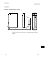
Appendix 1 External Dimension Diagram ................................................................................................App- 1
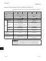
Appendix 2 Difference Between A1SD62, A1SD62E and A1SD62D (S1) .............................................App- 2
INDEX
A-7
Index- 1 to Index- 2
A-7
Conformation to the EMC Directive and Low Voltage Instruction
For details on making Mitsubishi PLC conform to the EMC directive and low voltage
instruction when installing it in your product, please see Chapter 3, "EMC Directive
and Low Voltage Instruction" of the User's Manual (Hardware) of the PLC CPU to
use.
The CE logo is printed on the rating plate on the main body of the PLC that conforms
to the EMC directive and low voltage instruction.
By making this product conform to the EMC directive and low voltage instruction, it is
not necessary to make those steps individually.
About the Generic Terms and Abbreviations
Unless otherwise specified, this manual uses the following generic terms and
abbreviations to describe the Type QD62, QD62D and QD62E high-speed counter
module.
Generic Term/Abbreviation
DOS/V personal computer
Description of the abbreviation/general terms
®
DOS/V-compatible personal computer of IBM PC/AT and its compatible
Generic product name of the product types SWnD5C-GPPW-E, SWnD5C-GPPW-EA,
GX Developer
SWnD5C-GPPW-EV and SWnD5C-GPPW-EVA.
"n" in the model name is 4 or greater.
QCPU (Qmode)
GX Configurator-CT
Generic term of Q00JCPU, Q00CPU, Q01CPU, Q02CPU, Q02HCPU, Q06HCPU,
Q12HCPU, Q25HCPU, Q12PHCPU, Q25PHCPU
Generic term of counter module setting/monitor tool GX Configurator-CT (SW0D5CQCTU-E)
QD62
Abbreviation of the Type QD62 high-speed counter module
QD62E
Abbreviation of the Type QD62E high-speed counter module
QD62D
Abbreviation of the Type QD62D high-speed counter module
QD62(E/D)
Generic term of QD62, QD62E and QD62D
Product Structure
The product structure of this product is given in the table below.
Model Name
Product Name
Quantity
QD62
Type QD62 high-speed counter module
1
QD62E
Type QD62E high-speed counter module
1
QD62D
Type QD62D high-speed counter module
SW0D5C-QCTU-E
GX Configurator-CT Version 1 (1-license product)
(CD-ROM)
1
SW0D5C-QCTU-EA
GX Configurator-CT Version 1 (Multiple-license product)
(CD-ROM)
1
A-8
1
A-8
1 OVERVIEW
MELSEC-Q
1 OVERVIEW
This User's Manual describes the specifications, handling and programming method
for the QD62, QD62E and QD62D high-speed counter modules (QD62 (E/D)) used
together with the MELSEC-Q series CPUs.
The QD62(E/D) modules are available with the following I/O types, maximum counting
speeds and number of channels.
Item
I/O type
QD62
QD62E
QD62D
DC input sinking
DC input sourcing
Differential input
output
output
sinking output
Maximum counting
200 kPPS
speed
Number of channels
500 kPPS
2 channels
The QD62(E/D) modules have the following input methods for 1 phase/2 phase pulse input:
• Phase 1 pulse input multiple of 1 • Phase 1 pulse input multiple of 2 • CW/CCW
• Phase 2 pulse input multiple of 1 • Phase 2 pulse input multiple of 2
• Phase 2 pulse input multiple of 4
See Section 5.1 for details on the input methods.
An overview of QD62 (E/D) operation is shown in the figure below.
4) I/O signal
PLC CPU
Buffer memory
read/write
QCPU (Q mode)
QD62(E/D)
Pulse generator
Pulse
1)
Encoder
External
control signal
Controller
Pulse generator
Preset counter
function selection
CH1
3) Coincidence signal output (2 points)
CH2
3) Coincidence signal output (2 points)
2)
Pulse
3)
Encoder
External
control signal
Controller
Preset counter
function selection
4)
1) Counts the pulses to be input to the QD62 (E/D).
2) Preset or counter function can be selected with an external control signal.
3) The present count value and the coincidence output point setting value can be
compared to output a coincidence signal.
4) Using the sequence program, the I/O signal and buffer memory status of the
QD62 (E/D) can be verified.
Also, count start/stop, preset, and counter function can be selected.
1-1
1-1
1
1 OVERVIEW
MELSEC-Q
1.1 Features
1
The features of the QD62(ED) are as follows:
(1) Counting can be performed in a wide range (The count value can be
expressed within the range between –2147483648 and 2147483647)
The count values are stored as 2-channel 32-bit signed binary codes.
(2) The maximum counting speed can be changed
The maximum speed of the QD62D can be changed by selecting from among
500 k, 200 k, 100 k and 10 k, while that of the QD62 and QD62E can be selected
from among 200k, 100k and 10k. This allows an error-free count even with
gradual rise/fall pulses.
(3) Pulse input can be selected
The pulse input can be selected from 1 phase multiple of 1, 1 phase multiple of 2,
2 phase multiple of 1, 2 phase multiple of 2, 2 phase multiple of 4, CW and CCW.
(4) Counter format can be selected
Either one of the following counter formats can be selected.
(a) Linear counter format
A count from –2147483648 to 2147483647 is possible and if the count
exceeds the range, an overflow will be detected.
(b) Ring counter format
Counting is performed repeatedly between the ring counter maximum value
and minimum value.
(5) Coincidence output is possible
Any channel coincidence output point can be preset to compare with the present
counter value to output the ON/OFF signal output, or to start an interrupt program.
(6) Selection can be made from four counter functions
One of the following four functions can be selected.
(a) Latch counter function
This function latches the present value of the counter when the signal was
input.
(b) Sampling counter function
This function counts the pulses that were input within the preset time period
from the signal input.
(c) Periodic pulse counter function
This function stores the present and previous values of the counter at each
preset time interval while the signal is being input.
(d) Disable count function
This function inputs a signal while executing the count enable command to
stop pulse counting.
1-2
1-2
1 OVERVIEW
MELSEC-Q
(7) The preset function/counter selection function can be executed
using an external control signal
By applying voltage to the preset terminal/function start terminal of an external
terminal, preset function/counter function selection can be executed.
(8) Easy settings using the utility package
A utility package is sold separately (GX Configurator-CT).
The utility package is not a required item. However, it can be used to set initial
settings and automatic refresh settings onscreen, reduce sequence programs,
and check settings and operating status.
(9) A blown fuse in the external output section can be detected
A blown fuse in the external output section can be detected; it is notified by the
input signal X and the LED display on the module.
1-3
1-3
2 SYSTEM CONFIGURATIONS
MELSEC-Q
2 SYSTEM CONFIGURATIONS
This chapter explains the system configuration of the QD62 (E/D).
2.1 Applicable System
2
This section explains the applicable system.
(1) Applicable CPU and number of modules that can be mounted
The CPU module and network module (for remote I/O station) that can have the
QD62 (E/D) and the number of modules that can be mounted are listed below.
Applicable module
CPU module
Network module
Number of modules that
can be installed
Q00JCPU
Maximum 16
Q00CPU
Q01CPU
Maximum 24
Q02CPU
Q02HCPU
Q06HCPU
Q12HCPU
Q25HCPU
Maximum 64
Q12PHCPU
Q25PHCPU
Maximum 64
QJ72LP25-25
QJ72BR15
QJ72LP25G
QJ71LP25GE
Maximum 64
Remarks
( 1)
Can be installed in Q mode only
( 1)
( 1)
MELSECNET/H Remote I/O
station ( 2)
1 See User's Manual (Function Explanation, Program Fundamentals) for the CPU module to use.
2 See Q Corresponding MELSECNET/H Network System Reference Manual (Remote I/O
network).
(2) Mountable base unit
QD62 (E/D) can be mounted on any of the base unit’s I/O slots ( 3). However,
depending on combinations with other mounted modules and the number of
mountings, there may be cases where the power capacity is insufficient. Be sure
to consider the power capacity when mounting the module.
3 Must be inside the point number range of 1 CPU unit and network module
(for remote I/O station).
(3) Compatibility with a multiple PLC system
First read the QCPU (Q mode) User's Manual (Function Explanation, Program
Fundamentals) if the QD62 (E/D) is used with a multiple PLC system.
(a) Compatible QD62 (E/D)
In case of using the QD62 (E/D) with the multiple PLC system, there is no
restriction by the version.
(b) Intelligent function module parameters
Perform PLC write of the intelligent function module parameters to the
control PLC of the QD62 (E/D) only.
2-1
2-1
2 SYSTEM CONFIGURATIONS
MELSEC-Q
(4) Software packages supported
Correspondence between systems which use QD62 (E/D) and software
packages are as shown below.
The GX Developer is necessary when using a QD62 (E/D).
Software Version
GX Developer
Single PLC
Q00J/Q00/Q01CPU
system
Multiple PLC
system
Single PLC
Q02/Q02H/Q06H/
system
Q12H/Q25HCPU
Multiple PLC
system
Q12PH/Q25PHCPU
Version 7 or later
Version 8 or later
Version 4 or later
Version 6 or later
Version 1.10L or later
(cannot be used with the
SW0D5C-QCTU-E 50F or
earlier versions)
SW0D5C-QCTU-E 00A or
later
SW0D5C-QCTU-E 50F or
later
Single PLC
Version 1.13P or later
system
(cannot be used with the
Multiple PLC
Version 7.10L or later
If installed in a MELSECNET/H
SW0D5C-QCTU-E 50F or
earlier versions)
system
remote I/O station
GX Configurator-CT
Version 6 or later
SW0D5C-QCTU-E 50F or
later
(5) Connector
For the QD62(D/E), the connector is sold separately.
See Section 4.3 and make separate arrangements for the connector.
2-2
2-2
2
2 SYSTEM CONFIGURATIONS
MELSEC-Q
2.2 How to Check Software Version
This section describes how to check the GX Configurator-CT software version.
(1) How to check the GX Configurator-CT software version
The GX Configurator-CT software version can be checked in GX Developer's
"Product information" screen.
[Startup procedure]
GX Developer
"Help"
Product information
Software version
(In the case of GX Developer Version 7)
REMARK
The version indication for the GX Configurator-CT has been changed as shown
below from the SW0D5C-QCTU-E 50F upgrade product.
Previous product
Upgrade and subsequent versions
SW0D5C-QCTU-E 50F
GX Configurator-CT Version 1.10L
2-3
2-3
2 SYSTEM CONFIGURATIONS
MELSEC-Q
2.3 About Use of the QD62 (E/D) with the Q00J/Q00/Q01CPU
Here, use of the QD62 (E/D) with the Q00J/Q00/Q01CPU is explained.
(1) Number of QD62 (E/D) that can be installed when the
Q00J/Q00/Q01CPU is used
See Section 2.1 concerning the number of QD62 (E/D) that can be installed
when the Q00J/Q00/Q01CPU is used.
(2) Limitations when using the Q00J/Q00/Q01CPU
To use the coincidence detection interrupt function, use the Q00J/Q00/Q01CPU
of function version B or later.
2.4 About Use of the QD62 (E/D) on the MELSECNET/H Remote I/O Station
Here, use of the QD62 (E/D) on the MELSECNET/H remote I/O station is explained.
(1) Number of QD62 (E/D) that can be installed when the remote I/O
station is used
See Section 2.1 concerning the number of QD62 (E/D) that can be installed
when the remote I/O station is used.
(2) Limitations when using the remote I/O station
(a) The coincidence detection interrupt function cannot be used.
(b) When the QD62 (E/D) is used on the MELSECNET/H remote I/O station, a
delay will occur due to the link scan time. Therefore, fully verify that there will
be no problem with controllability in the target system.
Example) When processing is executed using the counter value input by a
sequence program, variations will occur due to a delay in the link
scan time.
2-4
2-4
3 SPECIFICATIONS
MELSEC-Q
3 SPECIFICATIONS
The following describes the performance specifications, I/O signals for the PLC CPU
and buffer memory specifications of the QD62(E/D).
For the general specifications of the QD62(E/D), see the User's Manual (hardware) for
the CPU module used.
3.1 Performance Specifications
The following describes the performance specifications of the QD62(E/D):
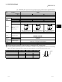
(1) QD62 (DC input sinking output type) performance specifications
3
Model name
QD62
Item
Counting speed switch settings
1
200 k (100 k to 200 kPPS)
I/O occupied points
100 k (10 k to 100 kPPS)
Number of channels
Count input
signal
2 channels
Phase
1-phase input, 2-phase input
Signal level (φ A, φ B)
Counting speed (max)
5/12/24 V DC 2 to 5 mA
2
200 kPPS
Counting range
100 kPPS
UP/DOWN Preset counter + Ring counter function
5
Minimum count pulse
width (µ s)
(Duty ratio 50 %)
10
2.5 2.5
5
(Min. phase differential for
2-phase input: 1.25 µ s)
Comparison range
5
50 50
(Min. phase differential for
2-phase input: 25 µ s)
32-bit signed binary values
Set value < Count value
Set value = Count value
Set value > Count value
Preset
5/12/24 V DC
2 to 5 mA
Function start
External
output
100
(Min. phase differential for
2-phase input: 2.5 µ s)
Coincidence
output
Comparison result
External
input
10 kPPS
32-bit signed binary values (–2147483648 to 2147483647)
Model
Counter
10 k (10 kPPS or less)
16 points (I/O assignment: Intelligent 16 points)
Transistor (sinking type) output
2 points/channel 12/24 V DC 0.5 A/1 point 2 A/1 common
Coincidence output
5V DC internal current consumption (A)
0.30
Weight (kg)
0.11
1: The counting speed switching can be set using the intelligent function module switch.
2: Counting speed is affected by pulse rise and fall time. Possible counting speeds are shown in the following
table. Note that if a pulse that has a large rise and/or fall time is counted, a miscount may occur.
Counting speed switch settings
200 k
Rise/fall time
100 k
10 k
Both 1 and 2 phase input
t = 1.25 µ s or less
200 kPPS
100 kPPS
10 kPPS
t = 2.5 µ s or less
100 kPPS
10 kPPS
t = 25 µ s or less
100 kPPS
—
t = 500 µ s
—
10 kPPS
—
500 PPS
3-1
10 kPPS
t
t
3-1
3 SPECIFICATIONS
MELSEC-Q
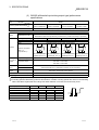
(2) QD62E (DC input sourcing output type) performance specifications
Model name
QD62E
Item
Counting speed switch settings
1
200 k (100 k to 200 kPPS)
I/O occupied points
100 k (10 k to 100 kPPS)
Number of channels
Count input
signal
2 channels
Phase
1-phase input, 2-phase input
Signal level (φ A, φ B)
Counting speed (max)
5/12/24 V DC 2 to 5 mA
2
200 kPPS
Counting range
100 kPPS
UP/DOWN Preset counter + Ring counter function
5
10
2.5 2.5
5
(Min. phase differential for
2-phase input: 1.25 µ s)
Comparison range
5
50 50
(Min. phase differential for
2-phase input: 2.5 µ s)
(Min. phase differential for
2-phase input: 25 µ s)
32-bit signed binary values
Coincidence
output
Comparison result
Set value < Count value
Set value = Count value
Set value > Count value
Preset
5/12/24 V DC
2 to 5 mA
Function start
External
output
100
3
Minimum count pulse
width (µ s)
(Duty ratio 50 %)
External
input
10 kPPS
32-bit signed binary values (–2147483648 to 2147483647)
Model
Counter
10 k (10 kPPS or less)
16 points (I/O assignment: Intelligent 16 points)
Transistor (sourcing type) output : 2 points/channel
12/24 V DC 0.1 A/1 point 0.4 A/1 common
Coincidence output
5V DC internal current consumption (A)
0.33
Weight (kg)
0.11
1: The counting speed switching can be set using the intelligent function module switch.
2: Counting speed is affected by pulse rise and fall time. Possible counting speeds are shown in the following
table. Note that if a pulse that has a large rise and/or fall time is counted, a miscount may occur.
Counting speed switch settings
200 k
Rise/fall time
100 k
10 k
Both 1 and 2 phase input
t = 1.25 µ s or less
200 kPPS
100 kPPS
10 kPPS
t = 2.5 µ s or less
100 kPPS
10 kPPS
t = 25 µ s or less
100 kPPS
—
t = 500 µ s
—
10 kPPS
—
500 PPS
3-2
10 kPPS
t
t
3-2
3 SPECIFICATIONS
MELSEC-Q
(3) QD62D (differential input sinking output type) performance
specifications
Model name
QD62D
Item
Counting speed switch settings
500 k
(200 k to 500 kPPS)
1
I/O occupied points
200 k
(100 k to 200 kPPS)
2 channels
Phase
1-phase input, 2-phase input
EIA Standard RS-422-A
Differential line driver level (Am26LS31 [manufactured by Texas Instruments] or equivalent)
Signal level (φ A, φ B)
Counting speed (max)
2
500 kPPS
Counting range
200 kPPS
100 kPPS
10 kPPS
32-bit signed binary values (–2147483648 to 2147483647)
Model
UP/DOWN Preset counter + Ring counter function
2
Counter
10 k
(10 kPPS or less)
16 points (I/O assignment: Intelligent 16 points)
Number of channels
Count input
signal
100 k
(10 k to 100 kPPS)
Minimum count pulse
width (µ s)
(Duty ratio 50 %)
1
5
1
10
2.5 2.5
5
100
5
50 50
(Min. phase differential for (Min. phase differential for (Min. phase differential for (Min. phase differential for
2-phase input: 0.5 µ s) 2-phase input: 1.25 µ s) 2-phase input: 2.5 µ s)
2-phase input: 25 µ s)
Comparison range
32-bit signed binary values
Coincidence
output
Comparison result
Set value < Count value
Set value = Count value
Set value > Count value
Preset
External
input
5/12/24 V DC 2 to 5 mA
(EIA Standard RS-422-A Differential Line Driver may be connected)
Function start
External
output
Transistor (sinking type) output 2 points/channel
12/24 V DC 0.5 A/1 point 2 A/1 common
Coincidence output
5 V DC internal current consumption (A)
0.38
Weight (kg)
0.12
1: The counting speed switching can be set using the intelligent function module switch.
2: Counting speed is affected by pulse rise and fall time. Possible counting speeds are shown in the following
table. Note that if a pulse that has a large rise and/or fall time is counted, a miscount may occur.
Counting speed switch settings
500 k
Rise/fall time
t = 0.5 µ s or less
500 kPPS
t = 1.25 µ s or less
t = 2.5 µ s or less
200 kPPS
—
t = 25 µ s or less
t = 500 µ s
3-3
200 k
100 k
10 k
Both 1 and 2 phase input
200 kPPS
100 kPPS
10 kPPS
200 kPPS
100 kPPS
10 kPPS
100 kPPS
10 kPPS
—
100 kPPS
—
10 kPPS
—
—
10 kPPS
—
t
t
500 PPS
3-3
3 SPECIFICATIONS
MELSEC-Q
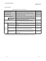
3.2 Function List
The QD62(E/D) functions are listed below.
Name
Linear counter function
Ring counter function
Coincidence output function
Function
Values from –2147483648 to 2147483647 can be counted. If the
count exceeds the range, this function detects an overflow.
Repeatedly executes counting between the ring counter
maximum and minimum values.
Reference section
Section 5.2.1
Section 5.2.2
Compares the coincidence output point of any preset channel
with the present counter value, and outputs the ON/OFF signal.
Coincidence detection
Generates an interrupt signal to the PLC CPU when coincidence
interrupt function
is detected, and starts the interrupt program.
Section 5.3
Rewrites the present counter value to any numeric value.
Preset function
Performs preset using the sequence program or external preset
Section 5.4
input.
Disable count function
Latch counter function
Counter
function
selection
Stops the pulse count while the count enable command is being
executed.
Stores the present counter value at the time the counter function
selection start command signal is input in the buffer memory.
Section 6.2
Section 6.3
Counts the pulses that are input during the preset sampling time
Sampling counter function period from the time the counter function selection start
Section 6.4
command is input, and stores the count in the buffer memory.
Periodic pulse counter
function
While the counter function selection start command signal is
being input, stores the present value in the buffer memory at
Section 6.5
preset interval.
The functions can be used in combination. However, only either one of the linear counter function or ring
counter function can be used, and only one of the four counter functions can be selected.
3-4
3-4
3 SPECIFICATIONS
MELSEC-Q
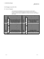
3.3 I/O Signals for the PLC CPU
3.3.1 List of I/O signals
The I/O signals for the QD62(E/D) PLC CPU are listed in the table below.
For the I/O numbers (X/Y) and I/O addresses indicated in this and succeeding
sections, it is assumed that the QD62(E/D) is mounted into I/O slot 0 of the standard
base module.
Input signal (Signal direction QD62(E/D)
PLC CPU)
Output signal (Signal direction PLC CPU
Device No.
Signal name
Device No.
X00
Module ready
Y00
QD62(E/D))
Signal name
Coincidence signal No. 1 reset command
X01
Counter value large (point No. 1)
Y01
Preset command
X02
Counter value coincidence (point No. 1)
Y02
Coincidence signal enable command
X03
Counter value small (point No. 1)
Y03
External preset request detection
Y04
X04
CH1
CH1
Down count command
Count enable command
X05
Counter value large (point No. 2)
Y05
External preset detection reset command
X06
Counter value coincidence (point No. 2)
Y06
Counter function selection start command
X07
Counter value small (point No. 2)
Y07
Coincidence signal No. 2 reset command
X08
Counter value large (point No. 1)
Y08
Coincidence signal No. 1 reset command
X09
Counter value coincidence (point No. 1)
Y09
Preset command
X0A
Counter value small (point No. 1)
Y0A
Coincidence signal enable command
X0B
CH2
External preset request detection
Y0B
X0C
Counter value large (point No. 2)
Y0C
X0D
Counter value coincidence (point No. 2)
Y0D
External preset detection reset command
X0E
Counter value small (point No. 2)
Y0E
Counter function selection start command
X0F
Fuse broken detection flag
Y0F
Coincidence signal No. 2 reset command
3-5
CH2
Down count command
Count enable command
3-5
3 SPECIFICATIONS
MELSEC-Q
3.3.2 Functions of I/O signals
The details of the I/O signals for the QD62(E/D) are listed in the table below.
(1) Input signals
Device No.
CH1
CH2
Signal name
QD62(E/D)
Description
PLC CPU
Turns ON when the count preparation for QD62(E/D) is completed at the
X00
Module ready
time of PLC CPU power on or reset operation, and count processing is
performed.
When Module ready (X00) is OFF, count processing is not performed.
X01
X08
X02
X09
Counter value large
Turns ON when the present value (CH1: 2H to 3H, CH2: 22H to 23H) >
(point No. 1)
coincidence output point No. 1 setting (CH1: 4H to 5H, CH2: 24H to 25H).
Counter value coincidence
(point No. 1)
Turns ON when the present value = coincidence output point No. 1
setting and the present value is latched.
Turns OFF with the coincidence signal No. 1 reset command (Y00/Y08).
Counter value small
Turns ON when the present value < coincidence output point No. 1
(point No. 1)
setting.
X03
X0A
X04
X0B External preset request detection and the request is latched.
Turns ON with a preset command signal from the external input terminal,
Turns OFF with the external preset detection reset signal (Y05/Y0D).
X05
X0C
X06
X0D
X07
X0E
X0F
3-6
Counter value large
Turns ON when the present value > coincidence output point No. 2
(point No. 2)
setting (CH1: 6H to 7H, CH2: 26H to 27H).
Counter value coincidence
(point No. 2)
Turns ON when the present value = coincidence output point No. 2
setting and the present value is latched.
Turns OFF with the coincidence signal No. 2 reset command (Y07/Y0F).
Counter value small
Turns ON when the present value < coincidence output point No. 2
(point No. 2)
setting.
Fuse broken detection flag
Fuse broken detection flag (X0F) turns ON when a fuse in the
coincidence signal output section is blown.
3-6
3 SPECIFICATIONS
MELSEC-Q
(2) Output signals
Device No.
Signal name
PLC CPU
QD62 (E/D)
CH1
CH2
Y00
Y08
Y01
Y09 Preset command
Y02
Y0A
Y03
Y0B Down count command
Y04
Y0C Count enable command
Y05
Y0D
Operation timing
Description
Coincidence signal No. 1 reset
Turns ON when the counter value coincidence (point
command
No. 1) signal (X02/X09) is reset.
Turns ON when the preset function is executed.
Coincidence signal enable
Turns ON when the counter value coincidence signal
command
(X02/X09, X06/X0D) is output to the external terminal.
Turns ON when a subtraction count is executed in the
1 phase pulse input mode.
Turns ON when the count operation is performed.
External preset detection reset
Turns ON when the external preset request detection
command
signal (X04/X0B) is reset.
Turns ON when counter function selection is
executed.
Y06
Y0E
Counter function selection start
• Latch counter function
command
• Sampling counter function
• Count disable function
• Periodic pulse counter function
Y07
Y0F
Coincidence signal No. 2 reset
Turns ON when the counter value coincidence (point
command
No. 2) signal (X06/X0D) is reset.
REMARK
The symbols used in the operation timing column signify the following:
……… Enabled while the signal is in ON status.
•
•
3-7
……… Enabled at signal rise (from OFF to ON).
3-7
3 SPECIFICATIONS
MELSEC-Q
3.4 Buffer Memory Assignments
(1) Buffer memory assignment list
Buffer memory assignments (without battery backup) for the QD62 (E/D) are
listed in the table below.
The initial values are set for the buffer memory when the power is turned on or
the PLC CPU is reset.
The contents of the buffer memory can be read/written using the FROM/TO
commands in the sequence program or the automatic refresh function of the PLC
CPU.
Address
CH1
CH2
Initial
Set data
Hexadecimal
Decimal
Hexadecimal
Decimal
0H
0
20H
32
1H
1
21H
33
2H
2
22H
34
3H
3
23H
35
4H
4
24H
36
5H
5
25H
37
6H
6
26H
38
7H
7
27H
39
8H
8
28H
40
Overflow detection flag
9H
9
29H
41
Counter function selection setting
AH
10
2AH
42
Sampling/periodic setting
Sampling/periodic counter flag
BH
11
2BH
43
CH
12
2CH
44
DH
13
2DH
45
EH
14
2EH
46
FH
15
2FH
47
10H
16
30H
48
11H
17
31H
49
12H
18
32H
50
13H
19
33H
51
14H
20
34H
52
15H
21
35H
53
16H
22
36H
54
17H
23
37H
55
18H
24
38H
56
to
to
to
to
1FH
31
3FH
63
Preset value setting
Present value
Coincidence output point set No. 1
Coincidence output point set No. 2
Latch count value
Sampling count value
Periodic pulse count previous value
Periodic pulse count present value
Ring counter minimum value
Ring counter maximum value
value
(L)
(H)
(L)
(H)
1
Read/write
0
Read/write enabled
0
Read only
0
Read/write enabled
0
Read only
0
Read/write enabled
0
Read only
0
Read/write enabled
—
—
(L)
(H)
(L)
(H)
(L)
(H)
(L)
(H)
(L)
(H)
(L)
(H)
(L)
(H)
(L)
(H)
System area
1: The initial values are set when the power is turned on or the PLC CPU is reset.
3-8
3-8
3 SPECIFICATIONS
MELSEC-Q
(2) Preset value setting (Buffer memory addresses CH1: 0H to1 H,
CH2: 20H to 21H)
• This area is used to set the values that are preset in the counter.
• The setting range is from –2147483648 to 2147483647 (32-bit signed binary
values).
(3) Present value (Buffer memory addresses CH1: 2H to 3H, CH2: 22H
to 23H)
• The present values for the counter are stored.
• The range of the values that are read is from –2147483648 to 2147483647
(32-bit signed binary values).
(4) Coincidence output point set No. 1 and No. 2
(Buffer memory addresses CH1: 4H to 7H, CH2: 24H to 27H)
• This area is used to write the setting values of the coincidence output points to
be compared with the present counter value.
• No. 1 and No.2 coincidence output points can be set for each channel.
• The setting range is from –2147483648 to 2147483647 (32-bit signed binary
value).
(5) Overflow detection flag (Buffer memory addresses CH1: 8H, CH2:
28H)
• A counter overflow occurrence status is stored when the counter format is
linear counter.
• The following values corresponding to the overflow occurrence status are
stored in this area.
Condition
Buffer memory content
No overflow detection
0
Overflow occurred
1
(6) Counter function selection setting (Buffer memory addresses CH1:
9H, CH2: 29H)
• This area is used to set the data for which a counter function is selected.
• The relationships between the selected counter function and set value are
shown below.
Counter function selection
3-9
Set value
Count disable function
0
Latch counter function
1
Sampling counter function
2
Periodic pulse counter function
3
3-9
3 SPECIFICATIONS
MELSEC-Q
(7) Sampling/periodic setting (Buffer memory addresses CH1: AH,
CH2: 2AH)
• This area is used to write the time setting values of the sampling counter
function and periodic pulse counter function during counter function selection.
• The setting range is from 1 to 65535 (16-bit binary values) and the time unit is
10[ms].
Example) When 420 is set for the sampling/periodic setting in the buffer
memory
420 10= 4200 [ms]
(8) Sampling/periodic counter flag (Buffer memory addresses CH1: BH,
CH2: 2BH)
• This area is used to store the function operating status while the sampling
counter function and periodic pulse counter function are being executed during
counter function selection.
• One of the values corresponding to the function operation status shown in the
table below is stored in this area.
Operating status
Buffer memory content
Idling function
0
Executing function
1
(9) Latch count value (Buffer memory addresses CH1: CH to DH,
CH2: 2CH to 2DH)
• This area is used to store the latch count values when the latch counter
function is executed.
• The range of the values to be read is from –2147483648 to 2147483647 (32-bit
signed binary values).
(10) Sampling count value (Buffer memory addresses CH1: EH to FH,
CH2: 2EH to 2FH)
• This area is used to store the sampling count values when the sampling
counter function is executed.
• The range of the values to be read is from –2147483648 to 2147483647 (32-bit
signed binary values).
(11) Periodic pulse count previous and present value
(Buffer memory addresses CH1: 10H to 13H, CH2: 30H to 33H)
• This area is used to store the present and previous values for the periodic
pulse count when the periodic pulse counter function is executed.
• The range of the values to be read is from –2147483648 to 2147483647 (32-bit
signed binary values).
(12) Ring counter minimum and maximum value
(Buffer memory addresses CH1: 14H to 17H, CH2: 34H to 37H)
• This area is used to set the count range when the counter format is ring counter.
• The setting range is from –2147483648 to 2147483647 (32-bit signed binary
values).
3 - 10
3 - 10
3 SPECIFICATIONS
MELSEC-Q
3.5 Interface with External Devices
The table below lists the external device interface for the QD62(E/D).
(1) QD62 (DC input sinking output type)
I/O
classification
Terminal
number 1
Internal circuit
4.7k
1/3W
3.3k
1/10W
470
1/16W
4.7k
1/3W
3.3k
1/10W
470
1/16W
Input
10k
1/3W
5.6k
1/10W
2k
1k
1/10W
1/10W
10k
1/3W
5.6k
1/10W
1k
1/10W
2k
1/10W
Output
To the fuse
broken detection
circuit
CH1
CH2
A20
A13
B20
A19
B13
A12
Signal name
A18
A11
Phase B pulse input 24 V
A10
—
—
B17
B10
A16
B16
A09
B09
A06
A05
B06
B05
When ON
10.8 to 13.2 V
2 to 5 mA
When OFF
4 V or less
0.1 mA or less
When ON
4.5 to 5.5 V
2 to 5 mA
When OFF
2 V or less
0.1 mA or less
When ON
21.6 to 26.4 V
2 to 5 mA
When OFF
5 V or less
0.1 mA or less
When ON
10.8 to 13.2 V
2 to 5 mA
When OFF
4 V or less
0.1 mA or less
When ON
4.5 to 5.5 V
2 to 5 mA
When OFF
2 V or less
0.1 mA or less
—
When ON
21.6 to 26.4 V
2 to 5 mA
When OFF
5 V or less
0.1 mA or less
When ON
10.8 to 13.2 V
2 to 5 mA
When OFF
4 V or less
0.1 mA or less
When ON
4.5 to 5.5 V
2 to 5 mA
When OFF
2 V or less
0.1 mA or less
Response
time
ON
OFF
0.5 ms or less
ON
OFF
1 ms or less
When ON
21.6 to 26.4 V
2 to 5 mA
When OFF
5 V or less
0.1 mA or less
When ON
10.8 to 13.2 V
2 to 5 mA
When OFF
4 V or less
0.1 mA or less
When ON
4.5 to 5.5 V
2 to 5 mA
When OFF
2 V or less
0.1 mA or less
Preset input 12 V
Preset input 5 V
Function start input 24 V
—
0.1 mA or less
Preset input 24 V
B08
—
5 V or less
—
B15
B07
When OFF
Phase B pulse input 5 V
CTRLCOM
B14
2 to 5 mA
Phase B pulse input 12 V
B08
A07
21.6 to 26.4 V
—
A15
A14
When ON
Phase A pulse input 5 V
ABCOM
A17
Operating current
(guaranteed value)
Phase A pulse input 12 V
B12
B11
Input voltage
(guaranteed value)
Phase A pulse input 24 V
B19
B18
Operation
Function start input 12 V
Function start input 5 V
Response
ON
ON
OFF
OFF
—
time
0.5 ms or less
1 ms or less
Operating voltage
10.2 to 30 V
EQU1
Maximum load current
0.5 A/point, 2 A/1 common
(Coincidence output point No. 1)
Maximum voltage drop when ON 1.5 V
ON 0.1 ms or less
Response time OFF
EQU2
ON
OFF 0.1 ms or less (rated load,
(Coincidence output point No. 2)
resistive load)
B02, B01
12/24 V
A02, A01
0V
FUSE
Input voltage
Current consumption
10.2 to 30 V
8 mA (TYP 24 V DC)
1: Terminal numbers A03, A04, B03 and B04 are not used.
3 - 11
3 - 11
3 SPECIFICATIONS
MELSEC-Q
(2) QD62E (DC input sourcing output type)
I/O
classification
Terminal
number 1
Internal circuit
4.7k
1/3W
3.3k
1/10W
470
1/16W
4.7k
1/3W
3.3k
1/10W
470
1/16W
Input
10k
1/3W
5.6k
1/10W
1k
1/10W
2k
1/10W
10k
1/3W
5.6k
1/10W
2k
1/10W
1k
1/10W
Output
CH1
CH2
A20
A13
B20
A19
B13
A12
A18
A11
Phase B pulse input 24 V
A17
A10
—
—
B17
B10
A16
B16
A09
B09
A06
A05
B06
B05
0.1 mA or less
When ON
10.8 to 13.2 V
2 to 5 mA
When OFF
4 V or less
0.1 mA or less
When ON
4.5 to 5.5 V
2 to 5 mA
When OFF
2 V or less
0.1 mA or less
When ON
21.6 to 26.4 V
2 to 5 mA
When OFF
5 V or less
0.1 mA or less
When ON
10.8 to 13.2 V
2 to 5 mA
When OFF
4 V or less
0.1 mA or less
When ON
4.5 to 5.5 V
2 to 5 mA
When OFF
2 V or less
0.1 mA or less
—
When ON
21.6 to 26.4 V
2 to 5 mA
When OFF
5 V or less
0.1 mA or less
When ON
10.8 to 13.2 V
2 to 5 mA
When OFF
4 V or less
0.1 mA or less
When ON
4.5 to 5.5 V
2 to 5 mA
When OFF
2 V or less
0.1 mA or less
Response
time
OFF ON
0.5 ms or less
ON OFF
1 ms or less
When ON
21.6 to 26.4 V
2 to 5 mA
When OFF
5 V or less
0.1 mA or less
When ON
10.8 to 13.2 V
2 to 5 mA
When OFF
4 V or less
0.1 mA or less
When ON
4.5 to 5.5 V
2 to 5 mA
When OFF
2 V or less
0.1 mA or less
Preset input 12 V
Preset input 5 V
Function start input 24 V
—
5 V or less
Preset input 24 V
B08
—
When OFF
—
B15
B07
2 to 5 mA
Phase B pulse input 5 V
CTRLCOM
B14
21.6 to 26.4 V
Phase B pulse input 12 V
B08
A07
When ON
—
A15
A14
Operating current
(guaranteed value)
Phase A pulse input 5 V
ABCOM
B11
Input voltage
(guaranteed value)
Phase A pulse input 12 V
B12
B18
Operation
Phase A pulse input 24 V
B19
FUSE
To the fuse
broken detection
circuit
Signal name
Function start input 12 V
Function start input 5 V
Response
ON OFF
OFF ON
time
0.5 ms or less
1 ms or less
Operating voltage
10.2 to 30 V
EQU1
Maximum load current
0.1 A/point, 0.4 A/1 common
(Coincidence output point No. 1)
Maximum voltage drop when ON 1.5 V
ON 0.3 ms or less
Response time OFF
EQU2
ON
OFF 0.3 ms or less (rated load,
(Coincidence output point No. 2)
resistive load)
—
B02, B01
12/24 V
A02, A01
0V
Input voltage
Current consumption
10.2 to 30 V
8 mA (TYP 24 V DC)
1: Terminal numbers A03, A04, B03 and B04 are not used.
3 - 12
3 - 12
3 SPECIFICATIONS
MELSEC-Q
(3) QD62D (Differential input sinking output type)
I/O
classification
Terminal
number 1
Internal circuit
CH1
CH2
A20
A14
Signal name
Operation
Input voltage
(guaranteed value)
Operating current
(guaranteed value)
+ 5V
(DC/DC converter)
27k
1/16W 4.7k
1/16W
Phase A pulse input
100
1/2W
Line
receiver
4.7k
1/16W
27k
1/16W
B20
B14
Phase A pulse input
A19
A13
Phase B pulse input
A19
B13
Phase B pulse input
A18
A12
Preset input 24 V
+ 5V
(DC/DC converter)
27k
1/16W 4.7k
1/16W
100
1/2W
Line
receiver
4.7k
1/16W
27k
1/16W
10k
1/3W
Input
5.6k
1/10W
1k
1/10W
680
1/10W
10k
1/3W
1k
1/10W
5.6k
1/10W
680
1/10W
Output
To the fuse
broken detection
circuit
Line driver level (Am26LS31 [manufactured by Texas
Instruments] or equivalent) that conforms to RS-422-A in
EIA Standard
EIA standard RS-422-A line driver level
Equivalent to Am26LS31 (made by Japan Texas
Instruments, Inc.)
Vhys Hysteresis (VT+ - VT-) 60 mV
VIH(E) "H" level enable input voltage: 2 V or higher
VIL(E) "L" level enable input voltage: 0.8 V or lower
A current type line driver cannot be used.
B18
A17
B12
A11
PRSTCOM
A16
A10
Function start input 24 V
A15
A09
B15
B09
A06
A05
B06
B05
2 to 5 mA
When OFF
5 V or less
0.1 mA or less
When ON
10.8 to 13.2 V
2 to 5 mA
When OFF
4 V or less
0.1 mA or less
When ON
2.5 to 5.5 V
2 to 5 mA
When OFF
1 V or less
0.1 mA or less
Response
time
OFF ON
0.5 ms or less
ON OFF
1 ms or less
When ON
21.6 to 26.4 V
2 to 5 mA
When OFF
5 V or less
0.1 mA or less
When ON
10.8 to 13.2 V
2 to 5 mA
When OFF
4 V or less
0.1 mA or less
When ON
2.5 to 5.5 V
2 to 5 mA
When OFF
1 V or less
0.1 mA or less
Preset input 5 V
B11
B10
21.6 to 26.4 V
Preset input 12 V
B17
B16
When ON
Function start input 12 V
Function start input 5 V
Response
ON OFF
OFF ON
time
0.5 ms or less
1 ms or less
Operating voltage
10.2 to 30 V
EQU1
Maximum load current
0.5 A/point, 2 A/1 common
(Coincidence output point No. 1)
Maximum voltage drop when ON 1.5 V
ON 0.1 ms or less
Response time OFF
EQU2
OFF 0.1 ms or less (rated load,
ON
(Coincidence output point No. 2)
resistive load)
FUNCCOM
B02, B01
12/24 V
A02, A01
0V
FUSE
Input voltage
Current consumption
10.2 to 30 V
8 mA (TYP 24 V DC)
1: Terminal numbers A08, A07, A03, A04, B08, B07, B04 and B03 are not used.
3 - 13
3 - 13
3 SPECIFICATIONS
MELSEC-Q
3.6 Encoders that can be Connected
The encoders that can be connected to the QD62(E/D) are described below.
(1) Encoders that can be connected to the QD62 and QD62E
• Open collector output type encoders
• CMOS level voltage output type encoders
(Verify that the encoder output voltage meets the specifications for the QD62
and QD62E.)
(2) Encoders that can be connected to the QD62D
• Line driver output type encoders
(Verify that the encoder output voltage meets the specifications for the
QD62D.)
POINT
The following encoders cannot be used with the QD62(E/D).
• TTL level voltage output type encoders
3 - 14
3 - 14
4 SETUP AND PROCEDURE BEFORE STARTING THE OPERATION
MELSEC-Q
4 SETUP AND PROCEDURE BEFORE STARTING THE OPERATION
The following describes the procedure prior to the QD62(E/D) operation, the name and
setting of each part of the QD62(E/D), and wiring method.
4.1 Handling Precautions
The following are the precautions for handling the QD62(E/D).
(1) Do not drop the module casing or connector, or do not subject it to strong impact.
(2) Do not remove the PCB of each module from its case. Doing so may cause
breakdowns.
(3) Be careful not to let foreign particles such or wire chips get inside the module.
These may cause fire, breakdowns and malfunctions.
4
(4) The top surface of the module is covered with a protective film to prevent foreign
objects such as wire chips from entering the module when wiring. Do not remove
this film until the wiring is complete.
Before operating the system, be sure to remove the film to provide adequate heat
ventilation.
(5) Tighten the mounting screws using torque within the following range. If the screws
are loose, it may cause short-circuits, breakdowns or malfunctions.
Screw location
Clamping torque range
Module mounting screws (M3 screws)
36 to 48 N · cm
(6) To mount the module on the base unit, fully insert the module fixing latch into the
fixing hole in the base unit and press the module using the hole as a fulcrum.
Improper installation may result in a malfunction or breakdown of the module, or
may cause the module to fall off.
4-1
4-1
4 SETUP AND PROCEDURE BEFORE STARTING THE OPERATION
MELSEC-Q
4.2 Procedure Before Starting the Operation
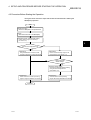
The figure below shows the steps that should be followed before starting the
QD62(E/D) operation.
Start
Module mounting
Mount the QD62(E/D) in the specified slot.
Wiring
Wire external devices to the QD62(E/D).
Intelligent function module switch setting
Perform settings using the GX Developer
(see Section 4.5)
4
Use the GX Configurator-CT?
Yes
No
Initial setting
Initial setting
Using the FROM/TO commands, create
a sequence program for writing initial values.
Perform the initial setting using the GX
Configurator-CT (see Section 7.4).
No
Perform automatic
refresh setting?
Yes
Automatic refresh setting
Perform the automatic refresh setting
using the GX Configurator-CT
(see Section 7.5).
Programming
Programming
Create and check a counter processing
program using the FROM/TO commands.
Create and check a counter processing
program without using the FROM/TO commands.
Operation
4-2
4-2
4 SETUP AND PROCEDURE BEFORE STARTING THE OPERATION
MELSEC-Q
4.3 Part Identification Nomenclature
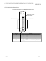
The names of the parts used in the QD62(E/D) are shown below:
QD62
φA
φB
DEC.
FUNC.
CH1 CH2
FUSE
External wiring connector
(40-pin connector)
(Connector terminal number)
A20
(Connector terminal number)
B20
B01
A01
QD62
LED name
Description
φA
Lit : Voltage is being applied to the Phase A pulse input terminal.
φB
Lit : Voltage is being applied to the Phase B pulse input terminal.
DEC.
FUNC.
Lit : Counter is in the process of subtraction.
Lit : Voltage is being applied to the function start input terminal.
Lit : Voltage is being applied to the external power supply input
FUSE
terminal while the fuse in the coincidence signal output section
is broken.
4-3
4-3
4 SETUP AND PROCEDURE BEFORE STARTING THE OPERATION
MELSEC-Q
(1) External wiring Connector
The connectors for use with the QD62(E/D) should be purchased separately by
the user.
The connector types are listed below.
(a) Connector types
Type
Model name
Soldering type, straight out
A6CON1
Solderless type, straight out
A6CON2
Pressure-welding type, straight out
A6CON3
Soldering type, usable for straight out and
diagonal out
4-4
A6CON4
4-4
4 SETUP AND PROCEDURE BEFORE STARTING THE OPERATION
MELSEC-Q
4.4 Wiring
The following explains how to wire the pulse generator and the controller to the QD62(E/D).
4.4.1 Wiring precautions
In order to fully utilise the functions of the QD62(E/D) and ensure system reliability,
external wiring having a minimum of noise effect must be provided.
The precautions regarding external wiring are described below.
(1) Different terminals have been prepared for connection depending on the voltage
of the input signal. Connecting a terminal of incorrect voltage may result in
malfunction or mechanical failure.
(2) For 1-phase input, always perform pulse input wiring on the Phase A side.
(3) For the QD62(E/D), count will be performed if pulse status noise is input and a
miscount will result.
(4) Provide the following measures against noise for high-speed pulse input:
(a) Always use a shielded twisted pair cable and provide grounding.
(b) Avoid placing the twisted pair cables or input/output cables. Place the cable
at least 150 mm (5.9 inch) from such wires and perform wiring using the
least distance as possible.
(5) An example of wiring incorporating measures against noise is shown below:
PLC
QD62 (E/D)
Inverter
Terminal block
Provide a clearance
of 150 mm (5.9 inch) or
more from I/O wires to
high voltage equipment
such as inverters. (Also
exercise caution for
wiring inside the panel.)
Do not enclose solenoids and inductive loads together within the same metal conduit.
If a sufficient distance cannot be secured to isolate ducts and other wires from a highvoltage line, use CVVS or other shielded wire for the high-voltage line.
AC
motor
The distance between the encoder and relay box
must be short. Allowing a long distance between
Relay box the QD62 (E/D) and the encoder may cause a
voltage-drop problem. Using a tester or other
measuring device, confirm that the voltage at the
terminal block of the relay box doesn't exceed the
rated voltage when the encoder is in operation or
at standstill. If a substantial voltage drop occurs,
increase the wire size or use a 24 V DC encoder
Encoder
with minimal current consumption.
Carrier
• Grounding the twisted pair shielded wire is performed on the encoder side (relay box). (This example shows
connection with 24 V sink load.
+ 24 V
Current for the encoder
To φ A
To φ B
To QD62 (E/D)
To the encoder
0V
φA
φB
24V
E
E
4-5
The shielded wire for the encoder
and twisted pair shielded wire are
connected inside the relay box .
If the shielded wire for the encoder
is not grounded inside the encoder,
ground it in the relay box, as
indicated by the dotted line.
4-5
4 SETUP AND PROCEDURE BEFORE STARTING THE OPERATION
MELSEC-Q
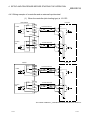
4.4.2 Wiring example of a module and a pulse generator
(1) Wiring example with an open collector output type pulse generator
(24 V DC)
QD62,QD62E
24 V
A20 (A13)
12 V
B20(B13)
Phase A
Twisted shield wire
Pulse generator
OUT
+24 V
Shield
5V
A19(A12)
E
ABCOM
B19(B12)
Twisted shield wire
24 V
A18(A11)
12 V
B18(B11)
Phase B
OUT
+24 V
Shield
5V
A17(A10)
External
power
supply
E
+24 V
24 V DC
0V
0V
The number inside the ( ) indicates the terminal number for channel 2.
POINT
When wiring the QD62, QD62E, and the encoder, separate the power supply cable
and signal cable. The following diagram shows an example.
[Wiring example]
QD62(E) 24 V
Phase ABCOM
A
OUT
+24 V
0V
Encoder
E
External 24 V DC
power
0V
supply
[Incorrect wiring example]
QD62(E) 24 V
Phase ABCOM
A
OUT
+24 V
0V
E
External 24 V DC
power
0V
supply
4-6
Encoder
The current flows
through the twisted
pair cables in the
same direction, so
there is no cancelling
effect. This makes it
more prone to electrom
agnetic induction.
4-6
4 SETUP AND PROCEDURE BEFORE STARTING THE OPERATION
MELSEC-Q
(2) Wiring example with a voltage output type pulse generator (5 V DC)
QD62,QD62E
Pulse generator
24 V
A20(A13)
12 V
B20(B13)
Phase A
5V
A19(A12)
Twisted shield wire
OUT
GND
ABCOM
B19(B12)
Shield
E
24 V
A18(A11)
12 V
B18(B11)
Phase B
5V
A17(A10)
Twisted shield wire
OUT
GND
Shield
External
power
supply
E
+5 V
5 V DC
0V
0V
The number inside the ( ) indicates the terminal number for channel 2.
(3) Wiring example with a driver (equivalent to Am26LS31) pulse
generator
QD62D
Pulse generator
A
A20(A14)
Phase A
A
B20(B14)
Twisted shield wire
A
A
Shield
E
B
A19(A13)
Phase B
B
B19(B13)
Twisted shield wire
B
B
Shield
E
External
power
supply
VCC
0V
VCC
0V
The number inside the ( ) indicates the terminal number for channel 2.
4-7
4-7
4 SETUP AND PROCEDURE BEFORE STARTING THE OPERATION
MELSEC-Q
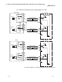
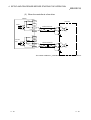
4.4.3 Wiring example of a controller and an external input terminal
(1) When the controller (sink loading type) is 12 V DC
QD62,QD62E
Controller
24 V
B17(B10)
Preset
12 V
A16(A09)
5V
B16(B09)
Twisted shield wire
OUT
Shield
+12 V
E
CTRLCOM
A15(A08)
24 V
B15(B08)
Function
start
12 V
A14(A07)
5V
B14(B07)
Twisted shield wire
OUT
Shield
+12 V
E
+
12 V DC
QD62D
Controller
24 V
A18(A12)
Preset
12 V
B18(B12)
5V
A17(A11)
Twisted shield wire
OUT
Shield
PRSTCOM
B17(B11)
+12V
E
24 V
A16(A10)
Function
start
12 V
B16(B10)
5V
A15(A09)
FUNCCOM
B15(B09)
Twisted shield wire
OUT
Shield
+12 V
E
+
12 V DC
The number inside the ( ) indicates the terminal number for channel 2.
4-8
4-8
4 SETUP AND PROCEDURE BEFORE STARTING THE OPERATION
MELSEC-Q
(2) When the controller (source loading type) is 5 V DC
QD62,QD62E
Controller
24 V
B17(B10)
12 V
A16(A09)
Preset
5V
B16(B09)
Twisted shield wire
OUT
GND
CTRLCOM
A15(A08)
Shield
E
24 V
B15(B08)
12 V
A14(A07)
Function
start
5V
B14(B07)
Twisted shield wire
OUT
GND
Shield
E
-
+
5 V DC
QD62D
Contrller
24 V
A18(A12)
Preset
12 V
B18(B12)
5V
A17(A11)
Twisted shield wire
OUT
GND
PRSTCOM
B17(B11)
Shield
E
24 V
A16(A10)
Function
start
12 V
B16(B10)
5V
A15(A09)
Twisted shield wire
OUT
GND
FUNCCOM
B15(B09)
Shield
E
-
+
5 V DC
The number inside the ( ) indicates the terminal number for channel 2.
4-9
4-9
4 SETUP AND PROCEDURE BEFORE STARTING THE OPERATION
MELSEC-Q
(3) When the controller is a line driver
QD62D
24 V
A18(A12)
Preset
Controller
12 V
B18(B12)
5V
A17(A11)
PRSTCOM
B17(B11)
Twisted shield wire
OUT
OUT
Shield
E
24 V
A16(A10)
Function
start
12 V
B16(B10)
5V
A15(A09)
FUNCCOM
B15(B09)
Twisted shield wire
OUT
OUT
Shield
E
The number inside the ( ) indicates the terminal number for channel 2.
4 - 10
4 - 10
4 SETUP AND PROCEDURE BEFORE STARTING THE OPERATION
MELSEC-Q
4.4.4 Wiring example with an external output
When the coincidence output (EQU terminal) is used, an external power supply of 10.2
to 30 V DC will be required for operation of the internal photocopier. A wiring example
is shown below.
(1) For QD62, QD62D (Sink output type)
QD62,QD62D
To fuse
broken
detection
circuitry
FUSE
EQU1
A06(A05)
L
EQU2
B06(B05)
L
12/24 V
B02,B01
0V
A02,A01
+
10.2 to 30 V DC
-
(2) For QD62E (Source output type)
QD62E
FUSE
To fuse
broken
detection
circuitry
EQU1
A06(A05)
L
EQU2
B06(B05)
L
12/24 V
B02,B01
0V
A02,A01
+
-
10.2 to 30 V DC
The number inside the ( ) indicates the terminal number for channel 2.
4 - 11
4 - 11
4 SETUP AND PROCEDURE BEFORE STARTING THE OPERATION
MELSEC-Q
4.4.5 Using the connector/terminal block converter module
(1) The figure below shows the wiring when a connector/terminal block converter
module and a cable are used in the QD62 (E/D).
QD62
φA
φB
DEC.
FUNC.
CH1 CH2
FUSE
QD62
Cable
AC05TB
AC10TB
AC20TB
AC30TB
AC50TB
AC80TB
AC100TB
Connector/ terminal block converter module
A6TBXY36
4 - 12
4 - 12
4 SETUP AND PROCEDURE BEFORE STARTING THE OPERATION
MELSEC-Q
(2) The following table lists the signal names and the corresponding connector side
terminal numbers and terminal block side terminal symbols, when a
connector/terminal block converter module is used in the QD62(E/D) .
For the QD62 and QD62E
Connector
side
terminal
number
Terminal
block side
terminal
symbol
Phase A pulse input 24 V
A20
10
Phase A pulse input 12 V
B20
0
Phase A pulse input 5 V
A19
Signal name
CH1
CH2
For the QD62D
Connector
side
terminal
number
Terminal
block side
terminal
symbol
Phase A pulse input (+)
A20
10
Phase A pulse input (–)
B20
0
11
Phase B pulse input (+)
A19
11
Signal name
ABCOM
B19
1
Phase B pulse input (–)
B19
1
Phase B pulse input 24 V
A18
12
Preset input 24 V
A18
12
Phase B pulse input 12 V
B18
2
Preset input 12 V
B18
2
Phase B pulse input 5 V
A17
13
Preset input 5 V
A17
13
Preset input 24 V
B17
3
Preset input 12 V
A16
14
CH1
PRSTCOM
B17
3
Function start input 24 V
A16
14
Preset input 5 V
B16
4
Function start input 12 V
B16
4
CTRLCOM
A15
15
Function start input 5 V
A15
15
Function start input 24 V
B15
5
FUNCCOM
B15
5
Function start input 12 V
A14
16
Function start input 5 V
B14
6
EQU1
(Coincidence output point No. 1)
A06
1E
EQU1
(Coincidence output point No. 1)
A06
1E
EQU2
(Coincidence output point No. 2)
B06
E
EQU2
(Coincidence output point No. 2)
B06
E
Phase A pulse input (+)
A14
16
Phase A pulse input (–)
B14
6
Phase A pulse input 24 V
A13
17
Phase B pulse input (+)
A13
17
Phase A pulse input 12 V
B13
7
Phase B pulse input (–)
B13
7
Phase A pulse input 5 V
A12
18
Preset input 24 V
A12
18
ABCOM
B12
8
Preset input 12 V
B12
8
Phase B pulse input 24 V
A11
19
Preset input 5 V
A11
19
Phase B pulse input 12 V
B11
9
Phase B pulse input 5 V
A10
1A
Preset input 24 V
B10
A
Function start input 12 V
B10
A
Preset input 12 V
A09
1B
Function start input 5 V
A09
1B
CH2
PRSTCOM
B11
9
Function start input 24 V
A10
1A
Preset input 5 V
B09
B
FUNCCOM
B09
B
CTRLCOM
A08
1C
Function start input 24 V
B08
C
EQU1
(Coincidence output point No. 1)
A05
1F
Function start input 12 V
A07
1D
F
B07
D
EQU2
(Coincidence output point No. 2)
B05
Function start input 5 V
EQU1
(Coincidence output point No. 1)
A05
1F
12/24 V
B02
B01
24 V
EQU2
(Coincidence output point No. 2)
B05
F
0V
A02
A01
0V
12/24 V
B02
B01
24 V
0V
A02
A01
0V
REMARK
If a connector/terminal block converter module is used in the QD62D, the terminals
on the terminal block side with symbols, C, D, 1C and 1D are not used.
4 - 13
4 - 13
4 SETUP AND PROCEDURE BEFORE STARTING THE OPERATION
MELSEC-Q
4.5 Switch Settings for the Intelligent Function Module
This section explains the switch settings for the intelligent function module. These
switch settings are performed with the GX Developer I/O assignments.
(1) Switch setting for the intelligent function module
Five switches (switch numbers 1 to 5) are available for the intelligent function
module and they are set with 16 bit data.
If the switches for the intelligent function module are not set, the default value of
0 is used for switches 1 to 5.
Data item
Pulse input mode
0
Switch 1
(for channel 1)
H
0: 1-phase multiple of 1
1: 1-phase multiple of 2
2: CW/CCW
3: 2-phase multiple of 1
4: 2-phase multiple of 2
5: 2-phase multiple of 4
Counting speed setting
0: 10 k PPS
1: 100 k PPS
Switch 2
(for channel 2)
2: 200 k PPS
3: 500 k PPS
(Only for the QD62D)
Counter format
0: Linear counter
1: Ring counter
Switch 3
Reserved
Switch 4
Reserved
Switch 5
Reserved
(Example) Target channel: Channel 2;
Counter format: Ring counter; Counting speed setting: 200 k PPS;
Pulse input mode setting: 2 phase multiple of 1
Set as switch 2 = 0123H
POINT
The counting speed setting of 500kPPS can only be used with the QD62D. Setting
the counting speed to 500k PPS for the QD62 and QD62E may cause miscounts.
Thus, do not use this setting for the QD62 and QD62E.
4 - 14
4 - 14
4 SETUP AND PROCEDURE BEFORE STARTING THE OPERATION
MELSEC-Q
(2) Detailed settings
The error time output mode and H/W error time PLC operation mode are set in
the detailed settings for the intelligent function module.
(a) Error time output mode
Sets to either clear or hold the module output status when a PLC CPU stop
error occurs.
• Clear : Tuns OFF all of the coincidence signal external outputs.
• Hold : Holds the same ON/OFF status before the CPU is stopped for the
coincidence signal external outputs.
(b) H/W error time PLC operating mode
Sets to either stop or continue the PLC CPU operation for each module
when an intelligent function module error (SP.UNIT DOWN) is detected.
• Stop
: PLC CPU stops operation.
• Continue : PLC CPU continues the execution of the programs for
modules other than those in which an error was detected.
An intelligent function module error in the QD62(E/D) is detected when the
Unit READY flag is not in the READY state due to a module hardware
failure.
4 - 15
4 - 15
4 SETUP AND PROCEDURE BEFORE STARTING THE OPERATION
MELSEC-Q
(3) Operating procedure
Perform settings, starting with the GX Developer I/O assignment screen.
(a) I/O assignment screen
Specify the following for the slot where the
QD62(E/D) is mounted.
Type
: Select "Intelli."
Model name : Enter the module's model name.
Points
: Select 16 points.
Start XY
: Enter the start I/O signal for the
QD62(E/D).
(b) Switch setting for I/O and intelligent function
module
Click on Switch Setting on the I/O assignment
screen to display the screen at left and set
switches 1 to 5. The setting can easily be done if
values are entered in hexadecimal. Change the
input format to hexadecimal and enter values.
(c) Intelligent function module detailed setting
Click on Detailed Setting on the I/O
assignment screen to display the screen at left,
and then set the error time output mode and H/W
error time PLC operation mode.
4 - 16
4 - 16
5 BASIC USAGE
MELSEC-Q
5 BASIC USAGE
This section explains the basic usage of the QD62 (E/D).
5.1 Understanding the Pulse Input and Counting Method
5.1.1 Types of pulse input methods
Six types of the pulse input methods are available. These include 1 phase multiple of
1, 1 phase multiple of 2, CW/CCW pulse input, 2 phase multiple of 1, 2 phase multiple
of 2, and 2 phase multiple of 4. The following table shows the pulse input methods and
count timings.
Pulse input method
Count timing
φA
For addition count
φB
Y03
(Y0B)
Count at φ A rise (
)
φ B, Y03 (Y0B) are OFF.
1-phase multiple of 1
φA
For subtraction count
5
φB
Y03
(Y0B)
φA
For addition count
φB
Y03
(Y0B)
Count at φ A fall (
)
φ B, Y03 (Y0B) are ON.
Count at φ A rise (
) and fall (
φ B, Y03(Y0B) are OFF
)
Count at φ A rise (
) and fall (
φ B, Y03(Y0B) are ON
)
1-phase multiple of 2
φA
For subtraction count
φB
Y03
(Y0B)
φA
For addition count
φB
CW/CCW
φA
For subtraction count
φB
Count at φ A rise (
φ B is OFF
)
φ A is OFF
Count at φ B rise (
)
Count at φ A rise (
) when φ B is OFF
φA
For addition count
φB
2-phase multiple of 1
φA
For subtraction count
Count at φ A fall (
) when φ B is OFF
Count at φ A rise (
Count at φ A fall (
) when φ B is OFF
) when φ B is ON
Count at φ A rise (
Count at φ A fall (
) when φ B is ON
) when φ B is OFF
Count at φ A rise (
Count at φ A fall (
Count at φ B rise (
Count at φ B fall (
) when φ B is OFF
) when φ B is ON
) when φ A is ON
) when φ A is OFF
Count at φ A rise (
Count at φ A fall (
Count at φ B rise (
Count at φ B fall (
) when φ B is ON
) when φ B is OFF
) when φ A is OFF
) when φ A is ON
φB
φA
For addition count
φB
2-phase multiple of 2
φA
For subtraction count
φB
φA
For addition count
φB
2-phase multiple of 4
φA
For subtraction count
φB
5-1
5-1
5 BASIC USAGE
MELSEC-Q
(1) Phase 1 pulse input
For phase 1 pulse input, either a multiple of 1 or multiple of 2 count method can
be selected.
The relationship between the phase A pulse input and the down count command
is shown below.
QD62(E/D)
Encoder
Pulse input
Down count command
(Or, when Y03 (Y0B) turns ON)
φA
φB
(2) CW/CCW pulse input
For CW/CCW pulse input, the up count is performed when there is a phase A
pulse input, and the down count is performed when there is a phase B pulse input.
The relationship between the phase A pulse input and phase B pulse input is
shown below.
QD62(E/D)
Encoder
Encoder
Addition pulse input
Subtraction pulse input
φA
φB
(3) Phase 2 pulse input
For phase 2 pulse input, either a multiple of 1, multiple of 2, or multiple of 4 count
method can be selected.
The phase difference between the phase A pulse and phase B pulse determines
whether the up count or down count is performed.
The relationship between the phase A pulse input and phase B pulse input is
shown below.
QD62(E/D)
Phase A pulse input
φA
Encoder
Phase B pulse input
5-2
φB
5-2
5
5 BASIC USAGE
MELSEC-Q
5.1.2 Setting the count method
The count method is set using the GX Developer intelligent function module.
See Section 4.5 for details on the setting method.
5.1.3 Reading the present values
This section explains the methods of reading the present values stored in the buffer
memory or the count values when counter function selection is executed.
(1) When any function is used, the present value is stored into the buffer memory for
storing the present value. When the latch counter, sampling counter or periodic
pulse counter function is executed, the count value is stored into the buffer
memory for storing the counter function selection count value at the addresses
shown in the table below, aside from the buffer memory for storing the present
value.
Counter function selection count value
Description
Buffer
memory
address
Present
value
Latch count
value
Sampling count
value
Periodic pulse
count previous
value
Periodic pulse
count present
value
CH1
2H to 3H
CH to DH
EH to FH
10H to 11H
12H to 13H
CH2
22H to 23H
2CH to 2DH
2EH to 2FH
30H to 31H
32H to 33H
(2) Both the present values and counter function selection count values are stored in
the buffer memory as 32-bit signed binary values. In addition, since the contents
of the buffer memory are automatically updated by the count operation, the latest
count values can be read from the buffer memory.
POINT
When reading the present values or the counter function selection count values,
use the DFRO command and always read values in two-word units. When reading
the values in one-word units, if the count values are updated in the middle of read
processing, a mismatch may occur between the data contents of the lower and
higher words, possibly causing the system to read incorrect count values.
[Program example]
X20
DFRO
H00
H02
D0
K1
FROM
H00
H03
D1
K1
FROM
H00
H02
D0
K1
[Example of an undesirable program]
X20
5-3
5-3
5 BASIC USAGE
MELSEC-Q
5.2 Selecting the Counter Format
Select either linear counter or ring counter with the GX Developer intelligent function
module.
See Section 4.5 for details on the setting method.
5.2.1 Selecting the linear counter
(1) Linear counter operation
When the linear counter is selected, the count operation is performed between
–2147483648 (minimum value) and +2147483637 (maximum value).
The linear counter can be used in combination with the preset function and the
coincidence output function.
Counter present value
Overflow
+ 2147483647
0
Subtraction
Overflow
Addition
– 2147483648
(2) Overflow error
(a) When the counter format is linear counter, an overflow error occurs if the
present counter value exceeds –2147483648 (minimum value) during
subtraction or exceeds +2147483647 (maximum value) during addition.
(b) When an overflow error occurs, 1 is stored in the buffer memory overflow
detection flag (addresses CH1: 8H, CH2: 28 H) and the count stops . Even if
a pulse is input, the present value will not change from –2147483648 or
+2147483647.
(c) Performing a preset will cancel the overflow error.
When a preset is performed, 0 is stored in the buffer memory overflow
detection flag and the count resumes.
(d) When an overflow error occurs, a generated module error can be viewed on
the system monitor by clicking "Diagnosis" - "System monitor" menu in the
GX Developer.
5-4
5-4
5 BASIC USAGE
MELSEC-Q
5.2.2 Selecting the ring counter
(1) Ring counter operation
When the ring counter is selected, the count operation is performed repeatedly
between the ring counter minimum value (addresses CH1: 14H to 15H, CH2: 34H
to 35H) and maximum value (addresses CH1: 16H to 17H, CH2: 36H to 37H) that
were set arbitrarily in the buffer memory.
When the ring counter is being selected, an overflow error does not occur.
The ring counter can be used in combination with the preset function and the
coincidence output function.
Present counter value
Ring counter maximum value
Addition
Subtraction
Ring counter minimum value
(2) Ring counter count range
The count range for the ring counter is determined by the relationship between
the present values in the buffer memory (addresses CH1: 2H to 3H, CH2: 22H to
23H) at the time the count enable command {Y04 (Y0C)} turns ON or a preset is
executed and the ring counter minimum value/maximum value.
Normally the range used is "ring counter minimum value ≤ present value ≤ ring
counter maximum value".
• For up count
When the present value reaches the ring counter maximum value, the ring
counter minimum value is automatically stored as the present value.
• For down count
Even if the present value reaches the ring counter minimum value, the ring
counter minimum value will be retained as is. With the next subtraction pulse,
(ring counter maximum value –1) will be stored as the present value.
Whether during up count or down count, the ring counter maximum value will not
be stored in the buffer memory for storing the present values.
For example, if the count is enabled with the ring counter minimum value of 0, the
ring counter maximum value of 2000 and the present value of 500, the count
range and present value will change as shown in the figure below.
Ring counter minimum value
0
Ring counter maximum value
Present value
2000
500
2147483647
– 2147483648
Count range
Ring counter
minimum value
Present value
500
501
to
1998
1999
(2000)
0
Ring counter
maximum value
1
2
to
498
499
The ring counter maximum value,
2000, will not be stored in the
buffer memory for storing the
present values.
5-5
5-5
5 BASIC USAGE
MELSEC-Q
(a) The ring counter will operate as follows when the "present value < ring
counter minimum value" or "ring counter maximum value < present value".
• For up count
Even if the present value reaches the ring counter minimum value, the
ring counter minimum value will be retained as is. With the next addition
pulse, (ring counter maximum value +1) will be stored as the present
value.
• For down count
When the present value reaches the ring counter maximum value, the ring
counter minimum value is automatically stored as the present value.
Whether during up count or down count, the ring counter maximum value
will not be stored in the buffer memory for storing the present values.
For example, if the count is enabled with the ring counter minimum value of
0, the ring counter maximum value of 2000 and the present value of 3000,
the count range and present value will change as shown in the figure below.
Ring counter minimum value Ring counter maximum value
0
2000
Present value
3000
– 2147483648
2147483647
Count range
Present value
3000
Count range
Ring counter
minimum value
3001 to 2147483647 –2147483648 to – 2
–1
(2000)
0
Ring counter
maximum value
2001
2002
to
2998
2999
The ring counter maximum value,
2000, will not be stored in the buffer
memory for storing the present values.
(b) When the "ring counter's minimum value is equal to the ring counter's
maximum value", the count range will cover any value that can be expressed
in 32-bit signed binary values (-2147483648 to +2147483637), regardless of
the present value.
POINTS
(1) When the count enable command {Y04(Y0C)} is ON, the set values for the
buffer memory will not change even if values are written as the minimum value
and maximum value of the ring counter. To change the ring counter maximum
and minimum value settings, first turn the count enable command OFF.
(2) When the count range is to be changed using preset, always change it after
first turning the count enable command {Y04(Y0C)} OFF.
5-6
5-6
5 BASIC USAGE
MELSEC-Q
5.3 Using the Coincidence Output Function
The coincidence output function presets any count value, compares it with the present
counter value, and outputs a signal when they match. For the coincidence output, 2
points can be set for each channel. To use the coincidence signal external output, turn
ON the coincidence signal enable command {Y02(Y0A)}.
(1) Coincidence Output Operation
ON
Count-enable command
{Y04 (Y0C)}
OFF
Coincidence-signal enable command
{Y02 (Y0A)}
OFF
ON
Counter input pulse
Coincidence output point setting No. 1
Buffer memory
(Addresses 4H to 5H (24H to 25H))
Counter value small (point No. 1)
{X03 (X0A)}
1) 100
ON
OFF
2)
Counter value coincidence (point No. 1) ON
OFF
{X02 (X09)}
3)
Coincidence signal No. 1 reset command ON
OFF
{Y00 (Y08)}
4)
Counter value large (point No. 1)
{X01 (X08)}
ON
OFF
Buffer memory for storing present values
(Addresses 2H to 3H (22H to 23H))
Number
0
1
2
to
98
99
100
101 102 103
Description
The coincidence output point set values are written in advance as 32-bit signed
1)
binary values in the coincidence output point No. 1 buffer memory {addresses 4H
to 5H (24H to 25H)}.
2)
When the count value becomes the coincidence output point set value, the counter
value small signal turns OFF and the counter value coincidence signal turns ON.
When the coincidence signal reset command is turned ON, the counter value
3)
coincidence signal is reset. If the counter value coincidence signal stays ON, the
next coincidence signal cannot be output.
4)
5-7
When the counter value becomes greater than the coincidence output point set
value, the counter value large signal turns ON.
5-7
5 BASIC USAGE
MELSEC-Q
POINT
With the coincidence output function, set the coincidence output point before
turning the coincidence signal enable command ON, then reset the coincidence
signal (turning the command OFF to ON to OFF).
If the coincidence signal enable command is turned ON without performing the
above operation, the coincidence output will be performed since the coincidence
output point and present count value match in the initial state .
(2) Output status setting during a CPU stop error
The output status (clear/hold) can be set for the external output signal when a
CPU stop error occurs.
The output status is set using the GX Developer I/O assignment.
See Section 4.5 for details on the I/O assignment setting method.
(3) Coincidence detection interrupt function
The coincidence detection interrupt function generates an interrupt request for
the PLC CPU during coincidence detection. The interrupt processing program
can be started using this interrupt request.
(When the PLC CPU is a Q00J/Q00/Q01CPU, use function version B or later.)
(a) With the MELSEC-Q series intelligent function module, each module can
have up to 16 points of interruption factors (SI).
The QD62 (E/D) has 4 points of interrupt factors corresponding to the
coincidence outputs shown below.
SI No.
Interruption factor
0
Channel 1: Coincidence detection for coincidence output point No. 1
1
Channel 1: Coincidence detection for coincidence output point No. 2
2
Channel 2: Coincidence detection for coincidence output point No. 1
3
Channel 2: Coincidence detection for coincidence output point No. 2
4 to 15
Vacant
Timing of interrupt signal generation
I/O
signal
Counter value
coincidence
{X02/X06(X09/X0D)}
Coincidence signal
reset command
{Y00/Y07(Y08/Y0F)}
Interrupt request
Internal
processing
Clear interrupt request
PLC CPU program processing
5-8
Interrupt program
processing
(b) Assignment of the interruption factors (SI) and the interrupt pointers for PLC
CPU are set by selecting "PLC parameter" - "PLC system" - "Intelligent
function module setting" - "Interrupt pointer settings".
1) PLC side "Interrupt pointer start No."
Specify the starting number for the PLC CPU interrupt pointer.
Setting range: 50 to 255
5-8
5 BASIC USAGE
MELSEC-Q
2) PLC side "Interrupt pointer No. of units"
Specify the number of units for the interrupt execution conditions set by
the "Interrupt setting".
Setting range: 1 to 16 (units)
3) Intelli. unit side "Start I/O No."
Specify the start I/O number for the intelligent function module that
performed the interrupt setting.
Setting range: 0000 to 0FF0 (H)
4) Intelli. unit side "Start SI No."
Specify the number of the intelligent function module interrupt pointer
that was set by the interrupt setting, "Interrupt (SI) No.".
Setting range: 0 to 15
The following example shows SI 0 to 3 of the QD62(E/D) installed in the slot
where the start I/O is 20 being assigned to interrupt pointers I50 to I53.
(c) The following two methods are available for using only specific SI numbers:
1) Method using the parameter interrupt pointer setting
The interruption factors are used only for the start SI number and the
additional number of pointers, only which are specified in the dialog box
for the "Intelligent function module's interrupt point setting." For example,
if the start SI number is set as 1 and the number of pointers is set as 2,
only SI 1 and 2 are used. Also, the interrupt function cannot be used
when the parameter interrupt pointer setting has not been set.
2) Method using the IMASK command from the sequence program
When the IMASK command is used, interrupt program execution
enable/disable (interrupt mask) can be set for each interrupt pointer
number. Refer to the Q (Q Mode)/QnA Programming Manual for details
on the IMASK command.
POINT
A coincidence detection interrupt occurs when the counter value coincidence signal
rises (OFF ON). Thus, the next interrupt request does not occur unless the
coincidence signal is reset and the counter value coincidence signal is turned OFF.
5-9
5-9
5 BASIC USAGE
MELSEC-Q
5.4 Using the Preset Function
The preset function rewrites the present counter value to any numeric value called the
preset value. The preset function can be used when starting the pulse count from the
preset value.
The preset function has two preset methods: preset using a sequence program and
preset using an external control signal.
(1) Preset using a sequence program
Preset is performed by turning the preset command {Y01(Y09)} ON using the
sequence program.
Count enable command
{Y04 (Y0C)}
ON
OFF
Input pulse for counting
1)
Buffer memory used for
100
0
setting the preset value
{Addresses 0H to 1H (20H to 21H)}
2)
Preset command
{Y01 (Y09)}
ON
OFF
Buffer memory used for storing
the present value
{Addresses 2H to 3H (22H to 23H)}
Number
1)
0
1
2
to
65 66
67
100
101 102 103 104 105
Description
Any numeric value is written in 32-bit binary format into the preset value setting
buffer memory (Addresses 0H to 1H (20H to 21H)) for the QD62 (E/D).
At the start (OFF to ON) of the preset command, the preset value in the preset
2)
value setting buffer memory is preset in the present value storage buffer
memory. Preset can be executed regardless of whether the count enable
command {Y04(Y0C)} is ON or OFF.
5 - 10
5 - 10
5 BASIC USAGE
MELSEC-Q
(2) Preset using an external control signal
Preset is performed by applying ON voltage to the preset input terminal for
external input.
Count enable command
{Y04 (Y0C)}
ON
OFF
Counter input pulse
1)
Preset value setting buffer memory
{Addresses 0H to 1H (20H to 21H)}
100
0
2)
Preset command
(Preset input terminal)
External preset request
detection flag
{X04 (X0B)}
External preset request
detection reset command
{Y05 (Y0D)}
OFF
ON
OFF
1)
4)
ON
OFF
Present value storage buffer memory
{Addresses 2H to 3H (22H to 23H)}
Number
2)
3)
ON
0
1
2
to
65 66
67
100
101 to 123 124 100 101
Description
Any numeric value is written in 32-bit binary format into the preset value setting
buffer memory (Addresses 0H to 1H (20H to 21H)) for the QD62(E/D).
At the start (OFF to ON) of the preset command (voltage applied to the preset
2)
input terminal), the preset value in the preset value setting buffer memory is
preset in the present value storage buffer memory. Preset can be executed
regardless of whether the count enable command {Y04(Y0C)} is ON or OFF.
POINT
While the external preset request detection flag {X04(X0B)} is ON (3), preset
cannot be executed even if voltage is applied to the preset terminal or the preset
command {Y01(Y09)} is turned ON. Preset can be performed by turning ON (4) the
external preset request detection reset command {Y05(Y0D)} and turning OFF the
external preset request detection flag.
5 - 11
5 - 11
6 CONVENIENT USAGE
MELSEC-Q
6 CONVENIENT USAGE
6.1 Selecting the Counter Function
By selecting the counter function with the counter function selection setting, the disable
count function, latch counter function, sampling counter function and periodic pulse
counter function can be used.
The counter function selection can be executed by writing the data shown in the table
below into the counter function selection setting buffer memory (address 9H (29H)} and
by using the counter function selection start command (voltage applied to the function
start input terminal or turning Y06 (Y0E) ON using the sequence program).
Also, for the counter function selection, only one of the following four functions can be used.
Counter function selection
Set value
Remarks
Disable count function
0
Initial value (default)
Latch counter function
1
Sampling counter function
2
Periodic pulse counter function
3
(1) Disable count function
This function stops the count while the counter function selection start command
is being entered when the count enable command (Y04 (Y0C)) is ON.
(2) Latch counter function
This function latches the present value at the time the counter function selection
start command was entered to the latch count value (addresses CH to DH (2CH
to 2DH).
(3) Sampling counter function
This function counts the input pulses during the preset sampling period since the
time the counter function selection start command was entered.
(4) Periodic pulse counter function
This function stores the present value and previous value for each preset periodic
time while the counter function selection start command is being entered.
POINTS
(1) Change the counter function while the counter function selection start
command is OFF.
(2) The counter function selection can be executed either by turning Y06 (Y0E) ON
or applying voltage to the function start input terminal. Also, the signal that was
entered first takes precedence.
(3) Time settings for the sampling counter function and the periodic pulse counter
function are performed by writing data in a range from 1 to 65535 into the
sampling/periodic setting buffer memory {address AH (2AH)}. The time unit is 10 ms.
(Example) When 420 is specified in the sampling/periodic time setting buffer memory
Setting time = 420 10 = 4200 [ms]
6-1
6-1
6
6 CONVENIENT USAGE
MELSEC-Q
6.1.1 Reading the counter function selection count value
The counter function selection count values are stored when the counter function
selection is executed. The count values when the latch counter, sampling counter and
periodic pulse counter functions are executed are stored in the counter function
selection count value storage buffer memory at the addresses shown in the table
below.
Counter function selection count value
Contents
Buffer
CH1
Present
value
2H to 3H
Latch count
Sampling
value
count value
CH to DH
2CH to 2DH
Periodic pulse Periodic pulse
count previous count present
value
value
EH to FH
10H to 11H
12H to 13H
2EH to 2FH
30H to 31H
32H to 33H
memory
address
CH2 22H to 23H
The present values and counter function selection count values are stored as 32-bit
signed binary values in the buffer memory. Also, since the contents of the buffer
memory are automatically updated by the count operation, the latest count values can
be read from the buffer memory.
POINTS
(1) When reading the present and counter function selection count values, use the
DFRO command and always read values in two-word units. When reading
values in one-word units, if the count values are updated in the middle of read
processing, a mismatch may occur between the data contents of the lower and
higher words, possibly causing the system to read incorrect count values.
[Program example]
6
X20
DFRO
H00
H0E
D0
K1
FROM
H00
H0F
D1
K1
FROM
H00
H0E
D0
K1
[Example of an undesirable program]
X20
(2) Although the latch count value and present periodic pulse count value are
stored in different addresses, the same values are always stored (updated at
the same time). Thus, when the latch counter function or periodic pulse
counter function is executed, the present periodic pulse count value and latch
count value do not retain their previous values.
6-2
6-2
6 CONVENIENT USAGE
MELSEC-Q
6.1.2 Count error
With the counter function selection, an error occurs in the count when it is executed
using an external input (voltage applied to the function start input terminal) or by a
sequence program (counter function selection start command ON).
The following explains how to calculate the count error.
(1) Count error (maximum) due to input response delay when using an
external input
1 [ms]
pulse input speed [PPS]
multiple [count]
(2) Count error (maximum) when the counter function selection is
executed by a sequence program
1 scan time [s]
pulse input speed [PPS]
multiple [count]
(3) Count error (maximum) due to the internal clock when executing
the sampling counter function and periodic pulse counter function
Setting time [s]
6-3
pulse input speed [PPS]
10000
multiple [count]
6-3
6 CONVENIENT USAGE
MELSEC-Q
6.2 Using the Disable Count Function
The disable count function stops the count operation while the count enable command
is ON.
The relationships between the count enable command, counter function selection start
command and the present counter value are illustrated below.
1)
6)
8)
ON
Count-enable command
{Y04(Y0C)}
OFF
2)
3)
7)
9)
ON
Y06(Y0E)
OFF
Count function
selection start
command
4)
Function start
5)
ON
OFF
Pulse actually entered
Present value storage buffer memory
{Addresses 2H to 3H (22H to 23H)}
The count value to be stored
in the present value storage
buffer memory
0
Stops count
operation
Stops
count
operation
Number
1)
2)
3)
4)
5)
6)
7)
8)
9)
6-4
Stops
count
operation
Stops count operation
Description
Count operation starts when the count enable command {Y04 (Y0C)} turns ON.
Count operation stops when the counter function selection start command {Y06
(Y0E)} turns ON.
Count operation resumes when the counter function selection start command
{Y06 (Y0E)} turns OFF.
Count operation stops when the count function selection start command
(function start) turns on.
Count operation resumes when the count function selection start command
(function start) turns off.
Count operation stops when the count enable command turns OFF.
Count operation stops regardless of the status of the counter function selection
start command since the count enable command is OFF.
Count operation stays stopped even if the count enable command turns ON,
since the counter function selection start command is ON.
Count operation resumes when the counter function selection start command
turns OFF.
6-4
6 CONVENIENT USAGE
MELSEC-Q
6.3 Using the Latch Counter Function
The latch counter function latches the present counter value at the time a signal was
entered.
The relationships between the present counter value for the latch counter function, the
counter function selection start command and the latch count value storage buffer
memory are illustrated below:
ON
Count-enable command
{Y04 (Y0C)}
OFF
150
130
100
100
50
50
Present value storage buffer memory
{Addresses 2H to 3H (22H to 23H)}
0
0
1)
Counter function selection start command
{Y06 (Y0E), function start}
2)
3)
4)
ON
OFF
150
130
100
100
50
50
Latch count value storage buffer memory
{Addresses CH to DH (2CH to 2DH)}
0
0
When the counter function selection start command {Y06 (Y0E), function start input}
rises at points indicated by 1) to 4) in the figure above, the present counter value is
stored in the latch count value storage buffer memory {addresses CH to DH (2CH to
2DH)}. The latch counter function is executed regardless of whether the count enable
command {Y04 (Y0C)} turns ON/OFF.
6-5
6-5
6 CONVENIENT USAGE
MELSEC-Q
6.4 Using the Sampling Counter Function
The sampling counter function counts the pulses that are entered during the specified
sampling time period.
The relationships between the signals, buffer memory, etc. in the sampling counter
function are illustrated below.
5)
ON
OFF
Count-enable command
{Y04 (Y0C)}
200
100
Present value storage buffer memory
{Addresses 2H to 3H (22H to 23H)}
0
1)
ON
OFF
Counter function selection start command
{Y06 (Y0E), function start}
T
T
T
200
2)
100
4)
Sampling count value storage buffer memory
{Addresses EH to FH (2EH to 2FH)}
0
– 100
3)
Sampling/periodic counter flag storage
1
0
buffer memory
(Addresses BH to 2BH)
Number
1)
2)
3)
4)
5)
6-6
Description
The pulses entered are counted from 0 at the rise of the counter function
selection start command {Y06 (Y0E), function start input}.
When the specified sampling time period elapses, the count stops.
While the sampling counter function is being executed, 1 is stored in the
sampling/periodic counter flag storage buffer memory {address BH (2BH)}.
Even if the execution of the sampling counter function ends, the value in the
sampling count value storage buffer memory is saved.
The sampling counter function is executed regardless of whether the count
enable command {Y04 (Y0C)} turns ON/OFF.
6-6
6 CONVENIENT USAGE
MELSEC-Q
6.5 Using the Periodic Pulse Counter Function
The periodic pulse counter function stores the present and previous counter values for
each specified periodic time (T) as the present and previous values.
The relationships between the signals, buffer memory, etc. in the periodic pulse
counter function are illustrated below.
Count-enable command
{Y04 (Y0C)}
ON
6)
OFF
2)
200
200
4)
100
100
Present value storage buffer memory
{Addresses 2H to 3H (22H to 23H)}
0
Counter function selection start command
{Y06 (Y0E), function start}
3)
20
1)
0
ON
OFF
T
T
100
0
Sampling/periodic counter flag storage
buffer memory
(Addresses BH to 2BH)
6-7
T
4)
100
T
5)
80
3)
20
1)
0
3)
200
200
Previous periodic pulse count value storage
buffer memory
{Addresses 10H to 11H (30H to 31H)}
T
2)
200
200
Present periodic pulse count value storage
buffer memory
{Addresses 12H to 13H (32H to 33H)}
5)
80
5)
100
100
2)
0
0
4)
20
7)
1
0
6-7
6 CONVENIENT USAGE
MELSEC-Q
Number
Description
The present counter value of 0 is stored in the present periodic pulse count
1)
value storage buffer memory {addresses 12H to 13H (32H to 33H)} (hereinafter
called the present value buffer memory).
The present counter value of 200 is stored in the present value buffer memory.
The value 0 that has been stored in the present value buffer memory will be
2)
stored in the previous periodic pulse count value storage buffer memory
{addresses 10H to 11H (30H to 31H)} (hereinafter called the previous value buffer
memory).
The present counter value of 20 is stored in the present value buffer memory.
3)
The value 200 that has been stored in the present value buffer memory will be
stored in the previous value buffer memory.
The present counter value of 100 is stored in the present value buffer memory.
4)
The value 20 that has been stored in the present value buffer memory will be
stored in the previous value buffer memory.
The present counter value of 80 is stored in the present value buffer memory.
5)
The value 100 that has been stored in the present value buffer memory will be
stored in the previous value buffer memory.
6)
7)
6-8
The periodic pulse counter function is executed regardless of whether the count
enable command {Y04 (Y0C)} is ON or OFF.
Value 1 is stored in the sampling/periodic counter flag storage buffer memory
{address BH (2BH)} while the periodic pulse counter function is being executed.
6-8
7 UTILITY PACKAGE (GX Configurator-CT)
MELSEC-Q
7 UTILITY PACKAGE (GX Configurator-CT)
7.1 Utility Package Functions
Table 7.1 shows a list of the utility package functions.
Table 7.1 Utility Package (GX Configurator-CT) Function List
Function
Description
Reference section
(1) Performs initial settings for each channel to operate the QD62 (E/D).
Sets values for the following items that require initial setting.
Initial setting
• CH
Preset value setting
• CH
Coincidence output point set No.1
• CH
Coincidence output point set No.2
• CH
Counter function selection setting
• CH
Sampling/periodic setting [unit: 10 ms]
• CH
Ring counter maximum value
• CH
Ring counter minimum value
Section 7.4
(2) The data for which initial setting has been completed is registered in the
PLC CPU parameters, and automatically written to the QD62 (E/D)
when the PLC CPU is placed in the RUN status.
(1) Sets for each channel the QD62 (E/D) buffer memory that refreshes
automatically.
Auto refresh
• CH
Preset value
• CH
Latch count value
• CH
Sampling count value
• CH
Periodic pulse counter present value
• CH
Periodic pulse counter previous value
• CH
Sampling/periodic counter flag
• CH
Overflow detection flag
Section 7.5
7
(2) Values stored in the buffer memory of the QD62 (E/D) where automatic
refresh is set are automatically read when the PLC CPU executes the
END command.
Monitors and tests the buffer memory and I/O signals for the QD62 (E/D).
• X/Y device
Monitor/test
7-1
• CH
Preset function
• CH
Coincidence output function
• CH
Counter selection function
• CH
Ring counter function
Section 7.6
7-1
7 UTILITY PACKAGE (GX Configurator-CT)
MELSEC-Q
7.2 Installing and Uninstalling the Utility Package
See "Method of installing the MELSOFT Series" attached with the utility package
regarding the install and uninstall operation for the utility package.
7.2.1 User precautions
The following explains the precautions on using the Utility package:
(1) Important safety information
Since the utility is add-in software for GX Developer, make sure to read "Safety
Precautions" and the basic operating procedures in the GX Developer Operating
Manual.
(2) About installation
GX Configurator-CT is an add-in software package for GX Developer Version 4
or later products. Therefore, install GX Configurator-CT in a personal computer in
which GX Developer Version 4 or later product has been installed.
(3) About display screen errors while using the intelligent function
module utility
There may be cases in which the screen will not properly display while the
intelligent function module utility is being used, due to a lack of system resources.
If this occurs, close the intelligent function module utility first, and then close GX
Developer (program, comments, etc.) and other applications. Next, restart GX
Developer and the intelligent function module utility.
(4) To start the intelligent function module utility
(a) In GX Developer, select "QCPU (Q mode)" for the PLC series and specify the
project. If anything other than "QCPU (Q mode)" is selected for the PLC
series, or if no project is specified, the intelligent function module utility will not
start.
7
(b) Multiple intelligent function module utilities can be started.
However, the [Open file]/[Save file] parameter operations of the intelligent
function module can only be performed by a single intelligent function
module utility. Other intelligent function module utilities can perform the
[Monitor/test] operation only.
(5) How to switch screens when two or more intelligent function
module utilities are started
When two or more intelligent function module utility screens cannot be displayed
side by side, use the task bar to display the desired intelligent function module
utility screen on top of other screens.
7-2
7-2
7 UTILITY PACKAGE (GX Configurator-CT)
MELSEC-Q
(6) About the number of parameters that can be set in GX
Configurator-CT
The number of parameters that can be set by the GX Configurator for an
intelligent function module installed in the CPU module and in a remote I/O
station of the MELSECNET/H network system is limited.
Intelligent function module
installation object
Maximum number of parameter settings
Initial setting
Automatic refresh setting
Q00J/Q00/Q01CPU
512
256
Q02/Q02H/Q06H/Q12H/Q25HCPU
512
256
Q12PH/Q25PHCPU
512
256
MELSECNET/H remote I/O station
512
256
For example, if multiple intelligent function modules are installed in a remote I/O
station, set the GX Configurator so that the number of parameter settings of all
the intelligent function modules does not exceed the maximum number of
parameter settings.The total number of parameter settings is calculated
separately for the initial setting and for the automatic refresh setting.
The number of parameter settings that can be set for one module in the GX
Configurator-CT is as shown below.
Object Module
QD62/QD62E/QD62D
Initial setting
Automatic refresh setting
8 (Fixed)
14 (Maximum number of settings)
Example) Counting the number of parameter settings in the automatic refresh
setting
The number of settings in this one line is
counted as one setting.
The number of settings is not counted by columns.
Add up all the setting items in this setting screen,
then add them to the total for the other intelligent
function modules to get a grand total.
7-3
7-3
7 UTILITY PACKAGE (GX Configurator-CT)
MELSEC-Q
7.2.2 Operating environment
The operating environment of the personal computer where the GX Configurator-CT is
used is explained.
Item
Peripheral devices
Installation (Add-in) destination
1
®
Computer main unit
Hard disk
2
Add-in to GX Developer Version 4 (English version) or later
Personal computer on which Windows operates.
CPU
Refer to the following table "Used operating system and performance required for
Required memory
personal computer".
For installation
65 MB or more
free space For operation
10 MB or more
800 600 dot or more resolution
Display
®
®
®
®
®
®
3
Microsoft Windows 95 Operating System (English version)
Microsoft Windows 98 Operating System (English version)
Microsoft Windows Millennium Edition Operating System (English version)
®
®
Microsoft Windows NT Workstation Operating System Version 4.0 (English version)
Operating system
®
®
®
®
®
®
Microsoft Windows 2000 Professional Operating System (English version)
Microsoft Windows XP Professional Operating System (English version)
Microsoft Windows XP Home Edition Operating System (English version)
1: Install the GX Configurator-CT in GX Developer Version 4 or higher in the same language.
GX Developer (English version) and GX Configurator-CT (Japanese version) cannot be used in
combination, and GX Developer (Japanese version) and GX Configurator-CT (English version) cannot be
used in configuration.
2: GX Configurator-CT cannot be used as an add-in with GX Developer Version 3 or earlier versions.
3: Setting fonts Size of Windows for "Large Fonts" may cause the text to extend off screen. Therefore,
choose "Small Fonts".
R
Used operating system and performance required for personal computer
Operating system
®
Windows 95
®
Windows 98
Performance Required for Personal Computer
CPU
Required memory
Pentium 133MHz or more
®
32MB or more
®
32MB or more
®
32MB or more
®
32MB or more
®
64MB or more
®
128MB or more
®
128MB or more
Pentium 133MHz or more
®
Windows Me
Pentium 150MHz or more
®
Pentium 133MHz or more
Windows NT Workstation 4.0
®
Windows 2000 Professional
®
Windows XP
"XP compatibility
Professional
mode" and "Fast User
®
Windows XP
Switching" are not
Home Edition
supported.
7-4
Pentium 133MHz or more
Pentium 300MHz or more
Pentium 300MHz or more
7-4
7 UTILITY PACKAGE (GX Configurator-CT)
MELSEC-Q
7.3 Explanation of Utility Package Operations
7.3.1 How to perform common utility package operations
(1) Available control keys
Special keys that can be used during operations of the utility package and their
applications are shown in the table below.
Name of key
Esc
Application
Cancels a newly entered value when entering data in a cell.
Closes the window.
Tab
Ctrl
Moves between controls in the window.
Uses together with the mouse when multiple cells are selected
in the Test selected.
Delete
Deletes the character where the cursor is positioned.
When a cell is selected, clears all of the setting contents.
Back
space
Deletes the character where the cursor is positioned.
Moves the cursor.
Page
Up
Moves the cursor one page up.
Page
Down
Moves the cursor one page down.
Enter
Confirms the value entered in the cell.
(2) Data to be created with the utility package
The data and files shown below that are created with the utility package are also
used by GX Developer operations. Figure 7.1 shows which operation uses which
data or file.
<Intelligent module parameters>
(a) This data is created with the auto refresh setting, and stored in the intelligent
module parameter file of the project to be created using GX Developer.
Project
Program
Parameters
PLC Parameters
Network Parameters
Intelligent Module Parameters
(b) Steps 1) to 3) shown in Figure 7.1 are performed using the following
operations.
1) Operating using GX Developer.
[Project] [Open project] / [Save] / [Save as]
2) Operating on the intelligent module parameter setting module selection
screen of the utility.
[File] [Open file] / [Save file]
7-5
7-5
7 UTILITY PACKAGE (GX Configurator-CT)
MELSEC-Q
3) Operating using GX Developer.
[Online] [Read from PLC] / [Write to PLC] "Intelligent module
parameter"
Or, operate on the intelligent module parameter setting module selection
screen of the utility.
[Online] [Read from PLC] / [Write to PLC]
<Text file>
(a) A text file can be created by performing the initial setting or auto refresh
setting, or selecting Make text file on the monitor/test screen. Text files
can be utilized to create user documents.
(b) Text files can be saved to any directory.
However, a path (folder where the file is to be saved) cannot be created
during Make text file operation, so create a folder in advance for saving
®
the file using Windows Explorer.
GX Developer/
GX Configurator-CT
Disk
Project
Project
1)
A
2)
A
Personal computer
B
QCPU
3)
Q25HCPU
MODE.
RUN.
ERR.
USER.
BAT.
BOOT.
A: Indicates intelligent module parameters.
B: Indicates the data saved by text file creation.
A
USB
RS-232
Figure 7.1 correlation diagram for data created using the utility package
7-6
7-6
7 UTILITY PACKAGE (GX Configurator-CT)
MELSEC-Q
7.3.2 Operation overview
GX Developer screen
[Tools] – [Intelligent function utility] – [Start]
Intelligent module parameter setting
module selection screen
Enter "Start I/O No.", then select
"Package name" and "Module model name".
See Section 7.3.3
1)
Initial setting
7-7
Auto refresh
Initial setting screen
Auto refresh setting screen
See Section 7.4
See Section 7.5
7-7
7 UTILITY PACKAGE (GX Configurator-CT)
MELSEC-Q
1)
[Online] – [Monitor/test]
Select monitor/test module screen
Monitor/test
Enter "Start I/O No.", then select
"Package name" and "Module model name".
Monitor/test screen
See Section 7.6
7-8
7-8
7 UTILITY PACKAGE (GX Configurator-CT)
MELSEC-Q
7.3.3 Starting the intelligent function utility
[Purpose of operation]
Start the utility from GX Developer, and display the intelligent module parameter
setting module selection screen. The initial setting, auto refresh and select
monitor/test module (selecting the module for which monitoring/testing is to be
performed) screens can be started from this screen.
[Startup procedure]
[Tools]
[Intelligent function utility]
[Start]
[Setting screen]
[Explanation of items]
(1) How to start each screen
(a) Starting the initial setting
"Start I/O No. " "Package name"
"Module model name"
Initial setting
(b) Starting the auto refresh setting
"Package name"
"Start I/O No. "
"Module model name"
Auto refresh
(c) Select monitor/test module screen
[Online] [Monitor/test]
Enter the start I/O No. in hexadecimal
(2) Explanation of the screen command buttons
7-9
Delete
Deletes the initial settings and auto refresh setting for the selected
module.
Exit
Ends the intelligent module parameter setting module selection screen.
7-9
7 UTILITY PACKAGE (GX Configurator-CT)
MELSEC-Q
(3) Menu bar
(a) File items
File operations are performed for the intelligent module parameters for the
project opened by GX Developer.
[Open file]
: Opens the parameter file.
[Close file]
: Closes the parameter file. If changes have been made,
the dialog box asking whether to save the file appears.
[Save file]
: Saves the parameter file.
[Delete file]
: Deletes the parameter file.
[Exit]
: Ends the intelligent module parameter setting module
selection screen.
(b) Online items
[Monitor/test]
: Starts the select monitor/test module screen.
[Read from PLC] : Reads the intelligent module parameters from the CPU
module.
[Write to PLC]
: Writes the intelligent module parameters to the CPU
module.
POINT
(1) Saving the intelligent module parameter files
Since these files cannot be saved using the GX Developer's project save
operation, save the files using the intelligent module parameter setting
module selection screen mentioned above.
(2) Reading and writing the intelligent module parameters to and
from a PLC using GX Developer.
(a) Once the intelligent module parameters are saved in a file, they can be
read from and written to the PLC.
(b) Set the target PLC CPU using [Online]
Developer.
[Transfer setup] of GX
(c) When the QD62 (E/D) is mounted to the remote I/O station, use “Read
from PLC” and “Write to PLC” of GX Developer.
(3) Checking for the required utility
The head I/O is displayed in the Intelligent function module utility setting
screen, but a " " may be displayed for the model name.
This means that either the required utility is not installed or that the utility
cannot be started from the GX Developer.
Check for the required utility in [Tools] - [Intelligent function utility] - [Utility list...]
in GX Developer, and set it.
7 - 10
7 - 10
7 UTILITY PACKAGE (GX Configurator-CT)
MELSEC-Q
7.4 Initial Settings
[Purpose of operation]
Perform the initial settings for each channel to operate the QD62 (E/D).
Set the following initial setting parameters:
• Preset value
• Sampling/periodic setting
• Coincidence output point set No.1
• Ring counter maximum value
• Coincidence output point set No.2
• Ring counter minimum value
• Counter function selection setting
These initial settings eliminate the need to set sequence programs.
[Startup procedure]
"Start I/O No. "
"Package name"
"Module model name"
Initial setting
Enter the start I/O No. in hexadecimal
[Setting screen]
Channel 1
7 - 11
Channel 2
7 - 11
7 UTILITY PACKAGE (GX Configurator-CT)
MELSEC-Q
[Explanation of items]
(1) Explanation of the command buttons
Make text file
Outputs the screen display in a text file format.
End setup
Confirms the entry of set data and ends the operation.
Cancel
Cancels the set data and ends the operation.
POINT
Initial settings are stored in the intelligent module parameters.
After being written to the CPU module, the initial setting is made effective by either
(1) or (2).
(1) Cycle the RUN/STOP switch of the CPU module: STOP RUN STOP
RUN.
(2) With the RUN/STOP switch set to RUN, turn off and then on the power or reset
the CPU module.
If the initialization settings have been written by a sequence program, the
initialization settings will be executed during the STOP RUN of the CPU module.
Arrange so that the initial settings written by the sequence program are re-executed
during the STOP RUN of the CPU module.
7 - 12
7 - 12
7 UTILITY PACKAGE (GX Configurator-CT)
MELSEC-Q
7.5 Auto Refresh
[Purpose of operation]
Set the QD62 (E/D) buffer memory to be automatically refreshed, for each
channel.
Set the following auto refresh setting parameters:
• Present value
• Periodic pulse counter previous value
• Latch count value
• Sampling/periodic counter flag
• Sampling count value
• Overflow detection flag
• Periodic pulse counter present value
These auto refresh settings eliminate the need for reading by a sequence
program.
[Startup procedure]
"Start I/O No. "
"Package name"
"Module model name"
Auto refresh
Enter the start I/O No. in hexadecimal
[Setting screen]
7 - 13
7 - 13
7 UTILITY PACKAGE (GX Configurator-CT)
MELSEC-Q
[Explanation of items]
(1) Contents of the screen display
Module side buffer
size
Module side transfer
word count
Transfer direction
PLC side device
: Displays the size of the setting item buffer memory.
: Displays the number of words to transfer.
: " " indicates that data at the PLC CPU side is written to
the buffer memory.
" " indicates that data is read from the buffer memory to
the PLC CPU side.
: Enter the device at the CPU module to be automatically
refreshed.
The devices that can be used include X, Y, M, L, B, T, C,
ST, D, W, R, and ZR. When using bit devices, X, Y, M, L
or B, set a number that can be divided by 16 points
(examples: X10, Y120, M16).
Also, buffer memory data is stored in 16-point portions
starting with the device number that has been set. For
example, if X10 is set, data will be stored to X10 through
X1F.
(2) Explanation of the command buttons
Make text file
Creates a file containing the displayed screen data in a text
file format.
End setup
Confirms the entry of set data and ends the operation.
Cancel
Cancels the set data and ends the operation.
POINTS
• The auto refresh settings are stored in the intelligent module parameters. Once
the intelligent module parameters are written to the CPU module, they can be
enabled by turning the power OFF and then ON, or resetting the CPU module.
• Auto refresh settings cannot be changed from the sequence program. However,
it is possible to add a process similar to auto refresh by using the FROM/TO
commands of the sequence program.
7 - 14
7 - 14
7 UTILITY PACKAGE (GX Configurator-CT)
MELSEC-Q
7.6 Monitor/Test
7.6.1 Monitor/Test
[Purpose of operation]
Start the buffer memory monitoring/testing, and I/O signals monitoring/testing
from this screen.
[Startup procedure]
Select monitor/test module screen
"Module model name"
"Start I/O No.
"
"Package name"
Monitor/test
1 Enter the start I/O No. in hexadecimal
The screen can also be started from the GX Developer Version 6 or later system
monitor. Refer to GX Developer Operating Manual for details.
[Setting screen]
1)
X/Y monitor/
test screen
7 - 15
Preset
7 - 15
7 UTILITY PACKAGE (GX Configurator-CT)
MELSEC-Q
1)
Counter
selection
Coincidence
output
7 - 16
Ring counter
7 - 16
7 UTILITY PACKAGE (GX Configurator-CT)
MELSEC-Q
[Explanation of items]
(1) Contents of the screen display
Setting item : Displays the I/O signal or buffer memory name.
Current value : Displays the I/O signal status or present buffer memory value for
monitoring.
Setting value : Select or enter a value to be written to the buffer memory with a
test operation.
(2) Explanation of the command buttons
Current value display
Make text file
Start monitor / Stop monitor
Execute test
Displays the current value of the selected item.
(This command button is used to check text that
cannot be displayed in the current value field.
However, in this utility package, all items can be
displayed in the display fields).
Makes a file consisting of the displayed screen
contents in a text file format.
Selects whether or not to monitor the current
values.
Tests the selected item. To select more than one
item, select each additional item while holding
down the Ctrl key.
Close
Closes the currently displayed screen and
returns to the previously displayed screen.
REMARK
The following explains an example to change settings for the selected test operation
to the following:
• Counter function selection setting
: Sampling counter function
• Counter function selection start command (Y06) : ON
• Sampling/periodic setting [unit: 10 ms]
: 1000 ms
(1) Set "Sampling counter function" in the setting value field for CH
function selection setting.
(2) Set "ON" in the setting value field for CH
command (Y06).
(3) Click the setting value field for CH
Counter
Counter function selection start
Sampling/periodic setting [unit: 10 ms].
(4) After entering the sampling time, press the Enter key.
At this point, nothing has been written to the QD62 (E/D).
(5) Select the setting value fields that were specified in steps 1 to 4 while holding
down the Ctrl key.
Multiple items can also be selected by dragging with the mouse.
(6) Click Execute test to execute write operation.
Once write operation is completed, the values that were written will be displayed
in the current value field.
7 - 17
7 - 17
8 PROGRAMMING
MELSEC-Q
8 PROGRAMMING
Using a sample system configuration shown below, this chapter explains details of the
QD62 (E/D) programs in the following two scenarios: when GX Configurator-CT is
used and when GX Configurator-CT is not used.
When diverting any of the program examples introduced in this chapter to the actual
system, fully verify that there are no problems in the controllability of the target system.
System configuration used in the program explanation
QD62
QX10
QY10
X/Y0 to X/YF
X10 to X1F
Y20 to Y2F
QCPU
Power supply module
(1) System configuration
(2) Program conditions
This program uses QD62 to perform counting with the conditions listed below.
Set the pulse input mode, counting speed setting and ring/linear counter
selection with the GX Developer intelligent function module switch.
• Pulse input mode
: 2 phase multiple of 1
• Counting speed setting : 200 kPPS
• Applicable channel
: Channel 1
(a) Contents of initial setting
Item
8
Preset value
Setting value
2500
Coincidence output point No. 1
1000
Ring counter minimum value
1
–5000
Ring counter maximum value
1
5000
Sampling time setting
2
Periodic pulse time setting
10000 ms
3
5000 ms
1 Set only when a ring counter is used
2 Set only when the sampling counter function is used
3 Set only when the periodic pulse counter function is used
POINT
Programs that were used in earlier products such as A1SD62 (E/D/D-S1) cannot
be used because the I/O signals and the buffer memory configuration of these
products differ from those of QD62 (E/D). The conventional dedicated instructions
cannot be used.
8-1
8-1
8 PROGRAMMING
MELSEC-Q
(b) Devices used by the user
Description
Device
Description
Device
Count operation start signal
X10
Periodic pulse count data read signal
X1C
Current value read signal
X11
Periodic pulse count start signal
X1D
Coincidence output data setting signal
X12
Coincidence confirmation LED signal
Y20
Preset command signal
X13
Overflow occurrence confirmation LED signal
Y21
Count operation stop signal
X14
Initial setting complete signal
M10
Coincidence LED clear signal
X15
Current value storage
D0 to D1
Counter function execution start signal
X16
Latch count value storage
D2 to D3
Counter function execution stop signal
X17
Sampling count value storage
D4 to D5
Latch count data read signal
X18
Periodic pulse count present value storage
D6 to D7
Latch execution signal
X19
Periodic pulse count previous value storage
D8 to D9
Sampling count data read signal
X1A
Overflow status storage
Sampling count start signal
X1B
D10
Interrupt enabled flag storage for the IMASK
instruction
D20 to D35
8.1 Program Example When GX Configurator-CT is Used
8.1.1 Operating GX Configurator-CT
(1) Initial settings (see Section 7.4)
Set the values on the screen as shown below.
8
Setting item
Description
Setting
Preset value setting
Set the preset value.
2500
Coincidence output point set No. 1
Set the value for coincidence output point No. 1.
1000
Coincidence output point set No. 2
This is not used.
Counter function selection setting
Set the counter function to be used.
—
Set according to
When a counter function is not used, sets any function.
the function used.
Sampling/periodic setting
Set "1000" when the sampling counter function is used.
1000
[Unit: 10 ms]
Set "500" when the periodic pulse counter function is used.
500
Ring counter minimum value
Set only when the ring counter function is used.
–5000
Ring counter maximum value
Set only when the ring counter function is used.
5000
8-2
8-2
8 PROGRAMMING
MELSEC-Q
(2) Auto refresh settings (see Section 7.5)
Set the values as shown in the screen below. (Use channel 1.)
Setting item
Description
Setting
CH1 Present value
Set the device for storing the present value.
D0
CH1 Latch count value
Set the device for storing the latch count value.
D2
Set the device for storing the sampling count value when the
CH1 Sampling count value
sampling counter function is used.
CH1 Periodic PLS counter previous
Set the device for storing the previous periodic pulse count
value
value when the periodic pulse counter function is used.
CH1 Periodic PLS counter present value
CH1 Sampling/periodic counter flag
CH1 Overflow detection flag
Set the device for storing the present periodic pulse count
value when the periodic pulse counter function is used.
This is not used.
Set the device for storing the overflow detection result when
the linear counter function is used.
D4
D8
D6
—
D10
(3) Writing the intelligent module parameters (see Section 7.3.3)
Write the intelligent module parameters to the PLC CPU. This operation is
performed using the intelligent module parameter setting module selection
screen.
8-3
8-3
8 PROGRAMMING
MELSEC-Q
8.1.2 Program example
(a)
Set only when
the linear counter
is used
8-4
8-4
8 PROGRAMMING
MELSEC-Q
(a) When using the functions listed below, the following programs are inserted.
1) When the disable count function is used
2) When the latch counter function is used
3) When the sampling counter function is used
4) When the periodic pulse counter function is used
8-5
8-5
8 PROGRAMMING
MELSEC-Q
8.2 Program Example when GX Configurator-CT is not Used
Set only when
the ring counter
is used
(a)
8-6
8-6
8 PROGRAMMING
MELSEC-Q
(b)
Set only when
the linear counter
is used
(a) When using the sampling counter function and the periodic pulse counter
function, the following programs are inserted
1) When the sampling counter function is used
2) When the periodic pulse counter function is used
(b) When using the functions listed below, the following programs are inserted
1) When the disable count function is used
8-7
8-7
8 PROGRAMMING
MELSEC-Q
2) When the latch counter function is used
3) When the sampling counter function is used
4) When the periodic pulse counter function is used
8-8
8-8
8 PROGRAMMING
MELSEC-Q
8.3 Example of a Program Using the Coincidence Detection Interrupt Function
The following describes an example of a program that starts an interrupt program upon
detection of coincidence with the channel 1 coincidence output point No. 1.
(1) Interrupt point setting
Set the interrupt pointer by selecting "PLC parameter" - " PLC system" –
"Intelligent functional module setting" – "Interrupt point settings" in the project
data list of GX Developer.
(2) Program example
Before using an interrupt pointer, an interrupt must be enabled using the IMASK
instruction.
QD62(E/D) program
Interrupt program
8-9
8-9
9 TROUBLESHOOTING
MELSEC-Q
9 TROUBLESHOOTING
The following explains the types of errors that may occur when the QD62 (E/D) is
used, and how to troubleshoot them.
9.1 Error Information
The error information detected by the QD62 (E/D) is listed in the following chart.
Description/cause
Error information display location
Overflow error
Corrective action
1) Module status display on the GX Developer system Preset to clear the overflow error.
1) When the linear counter
monitor screen
was used, an add pulse
No status display: No overflow detected (no error)
was further input from the
Module error
: Overflow being occurred
current value 2147483647 2) Overflow detection flag
The following value is stored in buffer memory
2) When the linear counter
was used, a subtract pulse
address 08H (28H)
was further input from the
0: No overflow detected
current value -2147483647
1: Overflow being occurred
3) "Module error status bit" of the module information
read with the UNIRD instruction
00: No overflow detected (no module error)
10: Overflow being occurred (Moderate error)
Fuse broken detection
1) FUSE LED on the front of the module (red)
1) The fuse for the
coincidence signal external
output section has blown.
The fuse must be replaced by a
Off: No broken fuse detected
technician from the Service
On: Broken fuse detected
Center. Consult with our branch
2) Fuse broken detection flag (X0F)
Off: No broken fuse detected
office or distributor with detailed
description.
On: Broken fuse detected
3) "Broken fuse occurrence indicating bit" of the
module information read with the UNIRD
instruction
Off: No broken fuse detected
On: Broken fuse detected
POINT
If voltage is not being supplied to the external power supply input terminal, a broken
fuse will not be detected.
9-1
9-1
9
9 TROUBLESHOOTING
MELSEC-Q
9.2 The Count Operation is not Working
Check item
Corrective action
If the PLC CPU is showing an error display, correct the
Is the PLC CPU showing an error display?
operation by following the troubleshooting instructions in the
manual for the PLC CPU in use.
Is the φ A and φ B external wiring normal?
Check and correct the external wiring.
If the LED lights up, check the external wiring and the pulse
When voltage is directly applied to the φ A and φ B pulse
input terminals, does the φ A and φ B LED light up?
generator side and make necessary corrections.
If the LED does not light up, this is a hardware error so
contact our branch office or distributor for consultation and
give details of the malfunction.
Is the count enable instruction {Y04 (Y0C0)} ON?
Is the counter function selection start instruction {Y06 (Y0E)}
ON or is voltage being applied to the function start input
terminals?
Turn the count enable instruction {Y04 (Y0C0)} ON using a
sequence program.
If the disable count function has been set with the counter
selection function, turn OFF the counter function selection
start instruction {Y06 (Y0E)} or the function start input
terminal.
Is an overflow error occurring?
Preset to clear the overflow error.
9.3 The Count Value is not Normal
Check item
Corrective action
Does the pulse input method match the pulse input mode set Match the pulse input method and the pulse input mode set
by parameter switch setting?
by the parameter setting switch.
Is the maximum input pulse speed within the range of the
Change the counting speed set by parameter switch setting
counting speed set by parameter switch setting?
so that it is in line with the maximum input pulse speed.
Does the pulse waveform that was input meet the
performance specifications?
Check the pulse waveform by observing it with a
synchroscope, and input the correct waveform pulse if it does
not conform to the performance specifications.
Is the count value data processed as binary 32-bit data in a
Change the sequence program so that the count value data
sequence program?
is processed as binary 32-bit data.
Does the pulse input wiring use a twisted pair shielded
cable?
Use a twisted pair shielded cable for the pulse input wiring.
Separate the QD62 (E/D)'s ground cable.
9
Is noise entering from the QD62 (E/D)'s grounding section?
If the QD62 (E/D) case is contacting the grounding section,
detach it.
Have noise preventive measures been taken inside the panel Take noise preventative measures such as attaching a CR
and for adjacent equipment?
Is there sufficient clearance between high voltage equipment
and pulse input lines?
Has the same count been input for both CH1 and CH2 and
are the count values the same?
9-2
surge suppressor to a magnet switch.
Wire the pulse input line independently inside the panel,
separate the pulse input line from the power line by at least
150 mm (5.9 in.).
When the count values are different, this is a hardware error.
Contact our branch office or distributor for consultation and
give details of the problem.
9-2
APPENDIX
MELSEC-Q
APPENDIX
Appendix 1 External Dimension Diagram
QD62,QD62E,QD62D
QD62
φA
φB
DEC.
FUSE
98
(3.86)
FUNC.
CH1 CH2
QD62
90
(3.54)
(45)
(1.77)
27.4
(1.08)
Unit: mm (in.)
A value in parentheses shows the reference measurement when the A6CON1 is
installed.
App.
App - 1
App - 1
APPENDIX
MELSEC-Q
Appendix 2 Difference Between A1SD62, A1SD62E and A1SD62D (S1)
The following table lists the difference between A1SD62, A1SD62E and A1SD62D
(S1).
Model name
Function
Counting
QD62
D62D
(0 to 16777215)
16 points
32 points
200 kPPS
Linear counter
function
500 kPPS
No function
Function available
No function
(Preset and coincidence output function
can be used independently of the ring
counter setting)
Coincidence
detection function
100 kPPS
Function available
Function available
function
A1SD62D (S1)
32-bit unsigned binary counter
CW/CCW pulse input
Counter
A1SD62E
32-bit signed binary counter
points
Ring counter
A1SD62
(–2147483648 to 2147483647)
Number of I/O occupied
Maximum counting speed
D62E
200 kPPS
Function available
(The ring counter operation only between
the preset value and the coincidence output
point. Setting values cannot be changed
during operation)
Function available
Function available
(program interrupt allowed)
(coincidence detection only)
Function available
No function
Can be set
Cannot be set
Overflow detection
function
Maximum and minimum
value settings for the ring
counter function
Utility package support
Fuse broken detection
Function available
Function available
(Only broken fuses are detected, LED display)
No function
Function available
(Both broken fuses and external power
off are detected)
POINT
Programs that were used in earlier products such as A1SD62 (E/D/D-S1) cannot
be used because the I/O signals and the buffer memory configuration of these
products differ from those of QD62 (E/D). The conventional dedicated instructions
cannot be used.
App.
App - 2
App - 2
INDEX
Ind
[A]
Latch counter function.......................... 3-4, 6-5
Linear counter function ................................3-4
List ........................................................ 3-4, 7-1
Periodic pulse counter function ........... 3-4, 6-7
Preset function ................................... 3-4, 5-10
Sampling counter function ................... 3-4, 6-6
Ring counter function ...................................3-4
A6CON1 .......................................................... 4-4
A6CON2 .......................................................... 4-4
A6CON3 .......................................................... 4-4
A6CON4 .......................................................... 4-4
Applicable CPU modules ................................ 2-1
Auto refresh ................................................... 7-13
[B]
Buffer memory assignments ........................... 3-8
[C]
Clamping torque .............................................. 4-1
Coincidence detection interrupt function ........ 5-8
Coincidence detection interrupt function ........ 5-8
Coincidence output function..................... 3-4, 5-7
Common operations........................................ 7-5
Connector ........................................................ 4-4
Connector/terminal block converter
module ........................................................... 4-12
Count error....................................................... 6-3
Count method.................................................. 5-3
Count range..................................................... 5-5
Counter function .............................................. 6-1
CW/CCW pulse input ...................................... 5-2
[D]
Difference ....................................................App-2
Disable count function.............................. 3-4, 6-4
[H]
Handling precautions .......................................4-1
[I]
I/O signals list...................................................3-6
Initial settings .................................................7-11
Installing and uninstalling.................................7-2
Interface with external devices ......................3-11
Interface .........................................................3-11
Interruption .......................................................5-8
[L]
Latch counter function ............................. 3-4, 6-5
LED...................................................................4-3
Linear counter function ............................ 3-4, 5-4
[M]
Menu bar ........................................................7-10
Monitor/test.....................................................7-15
Mounting slot....................................................2-1
[N]
[E]
EMC directive .................................................. A-8
Encoders that can be connected .................. 3-14
Encoders........................................................ 3-14
Error information.............................................. 9-1
Error ................................................................. 6-3
External dimension diagram .......................App-1
External wiring connector................................ 4-4
Noise ................................................................4-5
Number of counter modules that can
be mounted ......................................................2-1
[O]
Operating environment ....................................7-4
Operation overview..........................................7-7
Overflow ...........................................................5-4
Overview ..........................................................1-1
[F]
Features........................................................... 1-2
Function
Coincidence output function................. 3-4, 5-7
Counter function .......................................... 6-1
Disable count function .......................... 3-4, 6-4
Index - 1
[P]
Part identification nomenclature ......................4-3
Performance specifications .............................3-1
Periodic pulse counter function ............... 3-4, 6-7
Index - 1
Ind
Phase 1 pulse input......................................... 5-2
Phase 2 pulse input......................................... 5-2
Precautions........................................4-1, 4-5, 7-2
Preset function........................................ 3-4, 5-10
Procedure before starting the operation......... 4-2
Procedure ........................................................ 4-2
Program conditions ......................................... 8-1
Programming................................................... 8-1
Pulse input method.......................................... 5-1
[R]
Reading
Count value.................................................. 6-2
Present value............................................... 5-3
Reading the present values ............................ 5-3
Ring counter function ............................... 3-4, 5-5
[S]
Sampling counter function ....................... 3-4, 6-6
Setup and procedure before starting
the operation.................................................... 4-1
SI...................................................................... 5-8
Software packages supported ........................ 2-2
Specifications .................................................. 3-1
Starting the utility............................................. 7-9
Startup ............................................................. 7-9
Switch setting for the intelligent
function module ............................................. 4-14
Switch ............................................................ 4-14
System configurations..................................... 2-1
[T]
Text file ............................................................ 7-6
The details of the I/O signals .......................... 3-6
Troubleshooting............................................... 9-1
[U]
User precautions ............................................. 7-2
Utility package function list.............................. 7-1
[W]
Wiring precautions........................................... 4-5
Wiring............................................................... 4-5
Index - 2
Index - 2
WARRANTY
Please confirm the following product warranty details before starting use.
1. Gratis Warranty Term and Gratis Warranty Range
If any faults or defects (hereinafter "Failure") found to be the responsibility of Mitsubishi occurs during use of the product
within the gratis warranty term, the product shall be repaired at no cost via the dealer or Mitsubishi Service Company.
Note that if repairs are required at a site overseas, on a detached island or remote place, expenses to dispatch an
engineer shall be charged for.
[Gratis Warranty Term]
The gratis warranty term of the product shall be for one year after the date of purchase or delivery to a designated
place.
Note that after manufacture and shipment from Mitsubishi, the maximum distribution period shall be six (6) months, and
the longest gratis warranty term after manufacturing shall be eighteen (18) months. The gratis warranty term of repair
parts shall not exceed the gratis warranty term before repairs.
[Gratis Warranty Range]
(1) The range shall be limited to normal use within the usage state, usage methods and usage environment, etc.,
which follow the conditions and precautions, etc., given in the instruction manual, user's manual and caution labels
on the product.
(2) Even within the gratis warranty term, repairs shall be charged for in the following cases.
1. Failure occurring from inappropriate storage or handling, carelessness or negligence by the user. Failure caused
by the user's hardware or software design.
2. Failure caused by unapproved modifications, etc., to the product by the user.
3. When the Mitsubishi product is assembled into a user's device, Failure that could have been avoided if functions
or structures, judged as necessary in the legal safety measures the user's device is subject to or as necessary
by industry standards, had been provided.
4. Failure that could have been avoided if consumable parts (battery, backlight, fuse, etc.) designated in the
instruction manual had been correctly serviced or replaced.
5. Failure caused by external irresistible forces such as fires or abnormal voltages, and Failure caused by force
majeure such as earthquakes, lightning, wind and water damage.
6. Failure caused by reasons unpredictable by scientific technology standards at time of shipment from Mitsubishi.
7. Any other failure found not to be the responsibility of Mitsubishi or the user.
2. Onerous repair term after discontinuation of production
(1) Mitsubishi shall accept onerous product repairs for seven (7) years after production of the product is discontinued.
Discontinuation of production shall be notified with Mitsubishi Technical Bulletins, etc.
(2) Product supply (including repair parts) is not possible after production is discontinued.
3. Overseas service
Overseas, repairs shall be accepted by Mitsubishi's local overseas FA Center. Note that the repair conditions at each FA
Center may differ.
4. Exclusion of chance loss and secondary loss from warranty liability
Regardless of the gratis warranty term, Mitsubishi shall not be liable for compensation to damages caused by any cause
found not to be the responsibility of Mitsubishi, chance losses, lost profits incurred to the user by Failures of Mitsubishi
products, damages and secondary damages caused from special reasons regardless of Mitsubishi's expectations,
compensation for accidents, and compensation for damages to products other than Mitsubishi products and other duties.
5. Changes in product specifications
The specifications given in the catalogs, manuals or technical documents are subject to change without prior notice.
6. Product application
(1) In using the Mitsubishi MELSEC programmable logic controller, the usage conditions shall be that the application will
not lead to a major accident even if any problem or fault should occur in the programmable logic controller device, and
that backup and fail-safe functions are systematically provided outside of the device for any problem or fault.
(2) The Mitsubishi general-purpose programmable logic controller has been designed and manufactured for applications
in general industries, etc. Thus, applications in which the public could be affected such as in nuclear power plants and
other power plants operated by respective power companies, and applications in which a special quality assurance
system is required, such as for Railway companies or National Defense purposes shall be excluded from the
programmable logic controller applications.
Note that even with these applications, if the user approves that the application is to be limited and a special quality is
not required, application shall be possible.
When considering use in aircraft, medical applications, railways, incineration and fuel devices, manned transport
devices, equipment for recreation and amusement, and safety devices, in which human life or assets could be greatly
affected and for which a particularly high reliability is required in terms of safety and control system, please consult
with Mitsubishi and discuss the required specifications.
Microsoft, Windows, Windows NT are registered trademarks of Microsoft Corporation in the United States
and other countries.
Adobe, Acrobat is a registered trademark of Adobe systems Incorporated.
Pentium, Celeron is a registered trademark of Intel Corporation in the United States and other countries.
Ethernet is a registered trademark of Xerox.co.ltd in the United States.
Other company and product names herein are either trademarks or registered trademarks of their respective
owners.
SPREAD
Copyright (c) 1996 FarPoint Technologies, Inc.
MITSUBISHI ELECTRIC
HEADQUARTERS
EUROPEAN REPRESENTATIVES
EUROPEAN REPRESENTATIVES
EUROPEAN REPRESENTATIVES
MITSUBISHI ELECTRIC
EUROPE
EUROPE B.V.
German Branch
Gothaer Straße 8
D-40880 Ratingen
Phone: +49 (0)2102 486-0
Fax: +49 (0)2102 486-1120
e mail: [email protected]
MITSUBISHI ELECTRIC
FRANCE
EUROPE B.V.
French Branch
25, Boulevard des Bouvets
F-92741 Nanterre Cedex
Phone: +33 1 55 68 55 68
Fax: +33 1 55 68 56 85
e mail: [email protected]
MITSUBISHI ELECTRIC
IRELAND
EUROPE B.V.
Irish Branch
Westgate Business Park, Ballymount
IRL-Dublin 24
Phone: +353 (0) 1 / 419 88 00
Fax: +353 (0) 1 / 419 88 90
e mail: [email protected]
MITSUBISHI ELECTRIC .
ITALY
EUROPE B.V
Italian Branch
Via Paracelso 12
I-20041 Agrate Brianza (MI)
Phone: +39 039 60 53 1
Fax: +39 039 60 53 312
e mail: [email protected]
MITSUBISHI ELECTRIC
SPAIN
EUROPE B.V.
Spanish Branch
Carretera de Rubí 76-80
E-08190 Sant Cugat del Vallés
Phone: +34 9 3 565 3131
Fax: +34 9 3 589 2948
e mail: [email protected]
MITSUBISHI ELECTRIC
UK
EUROPE B.V.
UK Branch
Travellers Lane
GB-Hatfield Herts. AL10 8 XB
Phone: +44 (0) 1707 / 27 61 00
Fax: +44 (0) 1707 / 27 86 95
e mail: [email protected]
MITSUBISHI ELECTRIC
JAPAN
CORPORATION
Office Tower “Z” 14 F
8-12,1 chome, Harumi Chuo-Ku
Tokyo 104-6212
Phone: +81 3 622 160 60
Fax: +81 3 622 160 75
MITSUBISHI ELECTRIC
USA
AUTOMATION
500 Corporate Woods Parkway
Vernon Hills, IL 60061
Phone: +1 847 478 21 00
Fax: +1 847 478 22 83
GEVA
AUSTRIA
Wiener Straße 89
AT-2500 Baden
Phone: +43 (0)2252 / 85 55 20
Fax: +43 (0)2252 / 488 60
e mail: [email protected]
TEHNIKON
BELARUS
Oktjabrskaya 16/5, Ap 704
BY-220030 Minsk
Phone: +375 (0)17 / 2104626
Fax: +375 (0)17 / 2275830
e mail: [email protected]
Getronics b.v.
BELGIUM
Control Systems
Pontbeeklaan 43
BE-1731 Asse-Zellik
Phone: +32 (0)2 / 467 17 51
Fax: +32 (0)2 / 467 17 45
e mail: [email protected]
TELECON CO.
BULGARIA
4, A. Ljapchev Blvd.
BG-1756 Sofia
Phone: +359 (0)2 / 97 44 058
Fax: +359 (0)2 / 97 44 061
e mail: —
INEA CR d.o.o.
CROATIA
Losinjska 4 a
HR-10000 Zagreb
Phone: +385 (0) 1 / 36 940-01
Fax: +385 (0) 1 / 36 940-03
e mail: [email protected]
AutoCont
CZECH REPUBLIC
Control Systems s.r.o.
Nemocnicni 12
CZ-70200 Ostrava 2
Phone: +420 59 / 6152 111
Fax: +420 59 / 6152 562
e mail: [email protected]
louis poulsen
DENMARK
industri & automation
Geminivej 32
DK-2670 Greve
Phone: +45 (0)43 / 95 95 95
Fax: +45 (0)43 / 95 95 91
e mail: [email protected]
UTU Elektrotehnika AS
ESTONIA
Pärnu mnt.160i
EE-10621 Tallinn
Phone: +372 (0)6 / 51 72 80
Fax: +372 (0)6 / 51 72 88
e mail: [email protected]
UTU POWEL OY
FINLAND
Box 236
FIN-28101 Pori
Phone: +358 (0)2 / 550 800
Fax: +358 (0)2 / 550 8841
e mail: [email protected]
UTECO A.B.E.E.
GREECE
5, Mavrogenous Str.
GR-18542 Piraeus
Phone: +302 (0)10 / 42 10 050
Fax: +302 (0)10 / 42 12 033
e mail: [email protected]
Meltrade Automatika Kft. HUNGARY
55, Harmat St.
HU-1105 Budapest
Phone: +36 (0)1 / 2605 602
Fax: +36 (0)1 / 2605 602
e mail: [email protected]
SIA POWEL
LATVIA
Lienes iela 28
LV-1009 Riga
Phone: +371 784 2280
Fax: +371 784 2281
e mail: [email protected]
UAB UTU POWEL
LITHUANIA
Savanoriu Pr. 187
LT-2053 Vilnius
Phone: +370 (0)52323-101
Fax: +370 (0)52322-980
e mail: [email protected]
Intehsis Srl
MOLDOVA
Cuza-Voda 36/1-81
MD-2061 Chisinau
Phone: +373 (0)2 / 562 263
Fax: +373 (0)2 / 562 263
e mail: [email protected]
Getronics b.v.
NETHERLANDS
Control Systems
Donauweg 2 B
NL-1043 AJ Amsterdam
Phone: +31 (0)20 / 587 6700
Fax: +31 (0)20 / 587 6839
e mail: [email protected]
Motion Control
NETHERLANDS
Automation b.v.
Markenweg 5
NL-7051 HS Varsseveld
Phone: +31 (0)315 / 257 260
Fax: +31 (0)315 / 257 269
e mail: —
Beijer Electronics AS
NORWAY
Teglverksveien 1
NO-3002 Drammen
Phone: +47 (0)32 / 24 30 00
Fax: +47 (0)32 / 84 85 77
e mail: [email protected]
MPL Technology Sp. z o.o. POLAND
ul. Sliczna 36
PL-31-444 Kraków
Phone: +48 (0)12 / 632 28 85
Fax: +48 (0)12 / 632 47 82
e mail: [email protected]
Sirius Trading & Services srl ROMANIA
Str. Biharia Nr. 67-77
RO-013981 Bucuresti 1
Phone: +40 (0) 21 / 201 1146
Fax: +40 (0) 21 / 201 1148
e mail: [email protected]
ACP Autocomp a.s.
SLOVAKIA
Chalupkova 7
SK-81109 Bratislava
Phone: +421 (02)5292-2254
Fax: +421 (02)5292-2248
e mail: [email protected]
INEA d.o.o.
SLOVENIA
Stegne 11
SI-1000 Ljubljana
Phone: +386 (0)1 513 8100
Fax: +386 (0)1 513 8170
e mail: [email protected]
Beijer Electronics AB
SWEDEN
Box 426
S-20124 Malmö
Phone: +46 (0)40 / 35 86 00
Fax: +46 (0)40 / 35 86 02
e mail: [email protected]
ECONOTEC AG
SWITZERLAND
Postfach 282
CH-8309 Nürensdorf
Phone: +41 (0)1 / 838 48 11
Fax: +41 (0)1 / 838 48 12
e mail: [email protected]
GTS
TURKEY
Darülaceze Cad. No. 43A KAT: 2
TR-80270 Okmeydani-Istanbul
Phone: +90 (0)212 / 320 1640
Fax: +90 (0)212 / 320 1649
e mail: [email protected]
CSC Automation
UKRAINE
15, M. Raskova St., Fl. 10, Off. 1010
UA-02002 Kiev
Phone: +380 (0)44 / 238 83 16
Fax: +380 (0)44 / 238 83 17
e mail: [email protected]
MITSUBISHI ELECTRIC
Gothaer Strasse 8 Phone: +49 2102 486-0
D-40880 Ratingen Hotline: +49 1805 000-765
EURASIAN REPRESENTATIVE
CONSYS
RUSSIA
Promyshlennaya St. 42
RU-198099 St Petersburg
Phone: +7 812 / 325 36 53
Fax: +7 812 / 325 36 53
e mail: [email protected]
ELEKTROSTYLE
RUSSIA
ul. Garschina 11
RU-140070 Moscow Oblast
Phone: +7 095/ 557 9756
Fax: +7 095/ 746 8880
e mail: [email protected]
ELEKTROSTYLE
RUSSIA
Krasnij Prospekt 220-1, Office 312
RU-630049 Novosibirsk
Phone: +7 3832 / 10 66 18
Fax: +7 3832 / 10 66 26
e mail: [email protected]
ICOS
RUSSIA
Ryazanskij Prospekt, 8A, Office 100
RU-109428 Moscow
Phone: +7 095 / 232 0207
Fax: +7 095 / 232 0327
e mail: [email protected]
SMENA
RUSSIA
Polzunova 7
RU-630051 Novosibirsk
Phone: +7 095 / 416 4321
Fax: +7 095 / 416 4321
e mail: [email protected]
SSMP Rosgidromontazh Ltd RUSSIA
23, Lesoparkovaya Str.
RU-344041 Rostov On Don
Phone: +7 8632 / 36 00 22
Fax: +7 8632 / 36 00 26
e mail: —
STC Drive Technique
RUSSIA
Poslannikov per., 9, str.1
RU-107005 Moscow
Phone: +7 095 / 786 21 00
Fax: +7 095 / 786 21 01
e mail: [email protected]
MIDDLE EAST REPRESENTATIVE
SHERF Motion Techn. Ltd
ISRAEL
Rehov Hamerkava 19
IL-58851 Holon
Phone: +972 (0)3 / 559 54 62
Fax: +972 (0)3 / 556 01 82
e mail: —
AFRICAN REPRESENTATIVE
CBI Ltd
SOUTH AFRICA
Private Bag 2016
ZA-1600 Isando
Phone: +27 (0)11 / 928 2000
Fax: +27 (0)11 / 392 2354
e mail: [email protected]
INDUSTRIAL AUTOMATION
Fax: +49 2102 486-7170 www.mitsubishi-automation.de
[email protected] www.mitsubishi-automation.com