1
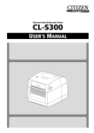
OD5
User Manual
Version EV1.140b
-1-
EMS AND EMI COMPLIANCE STATEMENT
FOR EUROPEAN USERS
This equipment has been tested and passed with the requirements relating to electromagnetic compatibility
based on the standards EN50081-1 (EN55022 CLASS A) and EN61000-4-2/-3/-4/-5/-6/-8/-11 (IEC Teil 2,3,4).
The equipment also tested and passed in accordance with the European Standard EN55022 for the both
Radiated and Conducted emissions limits.
THE OD5 THERMAL PRINTER
TO WHICH THIS DECLARATION RELATES
IS IN CONFORMITY WITH THE FOLLOWING STANDARDS
EN55022 : 1998,CLSPR 22 , Class A / EN55024 : 1998 IEC 61000-4 Serial / EN61000-3-2 : 2000 / EN 61000-33 : 1995 / CRF 47, Part 15/CISPR 22 3rd Edition : 1997,Class A / ANSI C63.4 : 2001 / CNS 13438,CISPR
22(Class A) / IEC60950 3rd Edition (1999) / GB4943 : 2001 / GB9254 : 1998 / GB17625.1 : 2003
CAUTION
Danger of explosion if battery is incorrectly replaced
Replace only with the equivalent type recommended by the manufacture.
Dispose of used batteries according to the manufacturer’s instructions.
Specifications are subject to change without notice.
-2-
CHAPTER 1 - BARCODE PRINTER.................................................................................4
1-1. INTRODUCTION ........................................................................................................................................4
1-2. PRINTER MODELS ....................................................................................................................................4
1-3. PRINTER ACCESSORIES ...........................................................................................................................4
1-4. GENERAL SPECIFICATIONS ......................................................................................................................5
1-5. COMMUNICATION INTERFACE ...................................................................................................................6
1-6. PRINTER PARTS ......................................................................................................................................7
CHAPTER 2 - PRINTER INSTALLATION ........................................................................8
2-1. RIBBON INSTALLATION.............................................................................................................................8
2-2. LABEL INSTALLATION ..............................................................................................................................8
2-3. LABEL ROLL CORE INSTALLATION INSTRUCTION .....................................................................................10
2-4. CARD / HANG TAGS INSTALLATION .........................................................................................................11
2-5. STRIPPER INSTALLATION........................................................................................................................11
2-6. STRIPPER INSTALLATION DIAGRAM ........................................................................................................13
2-9. PC CONNECTION ...................................................................................................................................14
CHAPTER 3 - OPTIONS INSTALLATION ......................................................................15
3-1. CUTTER PARTS .....................................................................................................................................15
3-2. CUTTER INSTALLATION ..........................................................................................................................15
3-3. EXTENDED MEMORY PARTS ...................................................................................................................18
3-4. EXTENDED MEMORY INSTALLATION ........................................................................................................19
CHAPTER 4 - LED MESSAGE DESCRIPTIONFEHLER! TEXTMARKE NICHT DEFINIERT.
4-1. LED STATUS .................................................................................. FEHLER! TEXTMARKE NICHT DEFINIERT.
4-2. GENERAL OPERATION .................................................................... FEHLER! TEXTMARKE NICHT DEFINIERT.
4-3. SELF-TEST ..................................................................................... FEHLER! TEXTMARKE NICHT DEFINIERT.
4-4. DUMP MODE ................................................................................... FEHLER! TEXTMARKE NICHT DEFINIERT.
4-5. AUTO SENSING ............................................................................... FEHLER! TEXTMARKE NICHT DEFINIERT.
4-6. DIRECT THERMAL / THERMAL TRANSFER MODE SWITCH .................. FEHLER! TEXTMARKE NICHT DEFINIERT.
4-7. ERROR MESSAGES ......................................................................... FEHLER! TEXTMARKE NICHT DEFINIERT.
4-7. ERROR MESSAGES ......................................................................... FEHLER! TEXTMARKE NICHT DEFINIERT.
CHAPTER 5 - MAINTENANCE AND ADJUSTMENT.....................................................27
5-1. THERMAL PRINT HEAD CLEANING ..........................................................................................................27
5-2. THERMAL PRINT HEAD BALANCE ADJUSTMENT ......................................................................................27
5-3. PRINT LINE ADJUSTMENT.......................................................................................................................28
5-4. ADJUST THE CUTTER .............................................................................................................................28
5-5. TROUBLESHOOTING ...............................................................................................................................29
-3-
Chapter 1 - Label Printer
1-1. Introduction
The OD5 is a desktop thermal transfer / direct thermal label printer. With plastic outer casing, the OD5 is
designed to be a lightweight and an economic printer for large variety of printing requirement. Its features are as
follows:
u
u
u
u
u
u
u
u
u
Direct Thermal and Thermal Transfer Printing Mode
Print head density of 8 dots per mm (203 dpi)
Memory for label, graphics, and fonts download (approximately 500KB)
Optional Real Time Clock for time recording and tracking
Internal 5” (125mm) label roll capacity and 300M (Max O.D. 64mm) ribbon length (0.5” core size)
Standard 2MB RAM for Maximum 68” print length
Standard stripper module for labels
Optional cutter for ticketing or receipt printing applications
Free Bundle of label editing software.
1-2. Printer Models
1-3. Printer Accessories
After unpacking, please check the accessories that come with the package, and store them appropriately.
(1)
(4)
(7)
(10)
Barcode Printer
Parallel Port Cable
Empty Roll Core
Quick Start Guide
(2)
(5)
(8)
(11)
Power Cables (220V)
Label Roll Core
Label Roll Sample
Product CD
(3)
(6)
(9)
Switching Power Adapter
Ribbon Shaft (2pcs)
Ribbon Roll Sample
* If a different power supply is used with the printer which has caused damages to the printer itself,
then this is not covered as part of the product warranty.
-4-
1-4. General Specifications
Model Name
OD5
Resolution
203 dpi (8 dot/mm)
Print Mode
Thermal Transfer / Direct Thermal
CPU
16 Bit
Sensor Location
Moveable, center aligned
Sensor Type
Reflective
Sensor Detection
Type: Label gap, black mark, and punch hole sensing.
Detection: Label length auto sensing and / or program command setting
Print Speed
2~4 IPS Standard
Print Length
Min. 12mm (0.47”); Max. 1727mm (68”)
Print Width
104mm (4.10")
Media
Label Roll OD: Max. 127mm (5”)
Core Diameter: 0.5”,1”, 1.5”, 3”
Width: 25mm (1 “) ~ 118mm (4.65”)
Thickness: 0.06~0.3mm (0.0025”~0.012”)
Ribbon
Length: 300M (981 ft)
Max. ribbon roll OD: 64mm (2.52 “)
Type: transfer ribbons (wax, wax/resin, resin) in widths of 30mm to 110mm (1.88” to 4.33”)
Core Inner Diameter: 0.5”
Printer Language
EPL2 ;Firmware Downloadable
Software / Driver
Application: Seagull Bartender Driver: Seagull OPAL OD
DLL & Driver: Microsoft Windows 95, 98, Me, NT 4.0, 2000 and XP
Resident Fonts
5 resident alphanumeric fonts (included OCR A & B) those are expandable 8 times
horizontally and vertically. All fonts in 4 directions rotation. 6,7,10,12,24,pts
Image Handling
PCX,
Barcode
Code 39, Code 93, Code 128 (subset A, B, C), UCC/EAN-128 K-Mart, UCC/EAN-128, UPC
A / E (add on 2 & 5), I 2 of 5, I 2 of 5 with Shipping Bearer Bars, EAN 8 / 13 (add on 2 & 5),
Codabar, Postnet, EAN 128, DUN 14, MaxiCode, PDF417 & Datamatrix code
Interface
Serial , Parallel, USB
Interface Transmission
Baud rate 4800 ~ 38400, XON/XOFF, DSR/DTR
Memory
DRAM: 2MB, FLASH: 1MB
LED Display
LED * 2, Bi-Color
Function Key * 1,FEED
Power
Auto Switching 100/240VAC, 50/60 Hz
Environment
Operation: 40°F to 104°F (5°C to 40°C) Storage: -40°F to 122°F (-20°C to 50°C)
Humidity
Operation: 30-85%, non-condensing. Free air.
Storage: 10-90%, non-condensing. Free air.
Cert. Approval
CE
Printer Dimension
Length:
285mm (11.2”)
Height: 171mm (6.8”)
Width: 226mm (8.9”)
Weight:
Options
2.72Kg
Rotary Cutter Module
1MB Flash Expansion Card + RTC (Real Time Clock)
2 MB Flash Expansion Card + RTC (Real Time Clock)
Internal Ethernet Adapter Card
Specifications are subject to change without notice.
-5-
1-5. Communication Interface
Parallel Interface
: Parallel cable compatible with IBM PC
: See below
Interface cable
Pin out
PIN NO.
1
2-9
10
11
12
13
14
15
16
17
18
19-30
31
32
33
34-35
36
FUNCTION
/Strobe
Data 0-7
/Acknowledge
Busy
/Paper empty
/Select
/Auto-Linefeed
N/C
Signal Gnd
Chasis Gnd
+5V,max 500mA
Signal Gnd
/Initialize
/Error
Signal Ground
N/C
/Select-in
TRANSMITTER
host / printer
host
printer
printer
printer
printer
host / printer
host
host / printer
printer
host / printer
Serial Interface
Serial Default Setting
: 9600 baud rate, no parity, 8 data bits, 1 stop bit, XON/XOFF protocol and RTS/CTS
RS232 HOUSING (9-pin to 9-pin)
DB9 SOCKET
--1
RXD
2
TXD
3
DTR
4
GND
5
DSR
6
RTS
7
CTS
8
RI
9
PC
1
2
3
4
5
6
7
8
9
DB9 PLUG
+5V,max 500mA
TXD
RXD
DSR
GND
DTR
N/C
RTS
N/C
PRINTER
NOTE: The total voltage output from parallel port and serial port altogether can not exceed 500mA.
USB Interface
Connector Type
: Type B
PIN NO.
1
2
3
4
FUNCTION
USBVCC
D-
D+
GND
-6-
1-6. Printer Parts
Please use the following diagrams to identify each printer part.
1
Cover Open Button
11 LED Light (Ready)
21 Power Socket
2
Top Cover
12 LED Light (Status)
22 USB Port
3
Label Roll Core
13 FEED Key
23 Parallel Port
4
Ribbon Rewind Wheel
14 Print Line Adj. Gear
24 Serial Port
5
15 Ribbon Supply Shaft
25 Ethernet Socket (Option)
16 Label Guide
26 Fan-Fold Label Insert
7
Print Mechanism
Ribbon Rewind Shaft + Empty
Ribbon Take Up Core
Locking Tenon (left/right)
17 Label Sensor
8
Stripper Module
18 Platen Roller
6
9
Memory Card Cover
Print Head Pressure Adj.
10
Screw (left/right)
19 PS2 Socket
20 Power Switch
-7-
Chapter 2 - Printer Installation
This printer model has the following print modes:
Thermal Transfer (TT): When printing, ribbon must be installed to transfer the print contents onto the media.
Direct Thermal (DT):
When printing, no ribbon is necessary; it only requires direct thermal media.
2-1. Label Installation
1.
Open the top cover by pressing the
Cover Open Buttons on both sides.
2.
Place the label roll onto the Label Roll
Core.
3.
Loosen and lift the upper print
mechanism by pressing the locking
tenons.
4.
Feed the label through the two Label
Guides to the Tear-off Bar.
5.
Align the label guides to the label edge.
6.
Close the upper print mechanism from
the top to finish label installation.
-8-
2-2. Ribbon Installation
1.
Open the top cover by
pressing the Cover Open
Buttons on both sides.
2.
Loosen and then lift the
upper print mechanism by
pressing the locking tenons.
3.
Take out the ribbon supply
shaft and rewind shaft.
4.
Place the new ribbon roll
onto the ribbon supply shaft.
5.
Feed the ribbon from the
Ribbon Supply Shaft under
the Print Head.
6.
Wrap the ribbon around the
Ribbon Shaft and stick the
ribbon onto the Empty
Ribbon Roll Core.
7.
Firmly close the upper print
mechanism.
-9-
2-3. Label Roll Core Installation Instruction
(A) 1” roll core installation instruction
(B) 1.5” roll core installation instruction
(C) 3” roll core installation instruction
- 10 -
2-4. Card / Hang tags Installation
When installing cord tags, the tag hole must align with the sensor
arrow (as indicated in Photo 1), then use the Label Guide to
secure the tags.
Tag hole position
Sensor Detection Position
2-5. Stripper Installation
1. Open the top cover by pressing
the Cover Open Buttons on both
sides.
2. Flip to open the stripper module.
- 11 -
(Photo 1)
3. Peel off the first label, and feed
the liner through the roller and
the peel off bracket.
4. Pull to level the label.
5. Flip to close the stripper module.
6. Close the print mechanism, and
then press the FEED key.
- 12 -
2-6. Stripper Installation Diagram
LABEL
LINER
LABEL
LINER
- 13 -
2-9. PC Connection
1.
2.
3.
4.
Please make sure the printer is powered off.
Take the power cable, plug the cable switch to the power socket, and then connect the other end of the
cable to the printer power socket.
Connect the cable to the parallel port on the printer and on the PC.
Power on the printer. The LED light (Ready) should turn green when power is on.
Remark: If you wish to connect with an USB interface, please install the USB driver first.
- 14 -
Chapter 3 - Options Installation
3-1. Cutter Parts
27 Cutter Module
28 Screw (TAP 3*8) x 2pcs
(Note 1)
Please power off the printer before installing
the cutter module.
(Note 2)
Do not cut self-adhesive labels! The traces of
adhesive will pollute the rotary knife and
impair safe operation! The service life of the
2
cutter is 500,000 cuts with 160g/m paper weight
2
and 250,000 cuts with 200g/m paper weight
(Note 3)
Max.paper cutting width: 116mm
[Suggestion]: When installing the cutter module, set the stop
Position to 29 in your driver. The E value is 29.
3-2. Cutter Installation
1.
Open the top cover by
pressing the Cover Open
Buttons on both sides.
2.
Flip to open the stripper
module.
- 15 -
3.
Hold the stripper module and
loose the screws.
4.
Lift/take off the stripper
module.
5.
Open the mechanism by
pressing the Locking Tenon,
plug in the cable connector of
the cutter module (26) onto
the switchboard socket.
Note: There are 2 sockets on
the converting boards (one is
for stripper installation, another
is for cutter installation), before
plug the connector into socket,
please check the pin first.
6.
Clip in the right side of the
cutter module (26) first, and
then secure the left side.
7.
Flip the cutter module (26)
down to open the cutter.
Note: Please refer to photo (A).
- 16 -
(A)
8.
Hold the cutter module and
lock it with the two side
screws (27).
9.
After the screws are locked,
flip close the cutter module.
10.
Close the mechanism to
complete the cutter module
installation.
- 17 -
3-3. Extended Memory Parts
28
29
Extended Memory Card
PCB Pillar x 2pcs
[NOTE]: Please power off the printer before
installing the extended memory.
- 18 -
3-4. Extended Memory Installation
1. Open the top cover by pressing
the Cover Open Buttons on both
sides.
2. Take off the media roll spindle.
Open and remove the plastic
cover on the inner base.
3.
Secure the PCB pillar onto the
main board.
- 19 -
4. Check the pins where the
memory is to be connected to,
then plug the memory card onto
the main board.
Note: Please make sure the
aperture on the connector and
the pins match, otherwise when
too much force is applied onto
the memory card, there’s a
possibility that the pins may get
damaged.
5. Close the plastic memory cover.
- 20 -
4. Control Panel
4-1. LED Status
LED colour
READY
Green
STATUS
READY
STATUS
Red (flashing)
Orange
READY
Orange (flashing)
STATUS
Orange
READY
Green (flashing)
STATUS
Orange
READY
Red (flashing)
STATUS
Red
READY
Orange (flashing)
STATUS
Red
Beep
Status
1
Normal
Status
3
Selftest
Ready for operation
Printer prints Selftest Label, point 4.3.2
1
Auto Sensing Printer is in selfrecognition Mode, point
Mode
4.3.4
1
Dump Mode Printer is in Dump-Mode, point 4.3.3
1
1
Direct
Thermal (DT)
Mode
Thermal
Transfer (TT)
Mode
READY
STATUS
Description
Printer is in Direct Thermal Mode (TD),
Punkt 4.3.5
Printer is in Thermal Transfer Mode (TT),
Punkt 4.3.5
Printer downloads Firmware
Red (flashing)
- 21 -
4-3. Operation
With the OD5 all important functions can be activated or alternatively completed with a certain key combination.
For this you have to switch off the printer. Afterwards you keep the FEED key pressed and switch the printer on.
The LED' s will now start to flash. If you release the FEED key, the function is activated, which is indicated with
the LED' s. In order to select another function, you have to start this procedure again right from the beginning.
You can find the postition of the FEED under point 1.6 (position 13).
The individual functions will be explained individually in the following.
The functions of the FEED keys at a glance:
4-3-1. FEED key
If the FEED key is pressed, the printer transports the printer material to the next print position. During printing of
continuous material, pressing the FEED key leads to the fact that the pressure material up to a certain length is
ejected. However, if label material is printed, an individual label is ejected when pressing the FEED key. If the
label length is not correct, please perform the automatic recognition of the label length (see 4-5).
- 22 -
4-3-2. Selftest Label
The self check function makes it easier for the user to find out if the the printer works correctly. In this mode the
printer prints out a self check side with each press on the FEED key. In order to stop the self check during the
procedure, please switch off the printer.
In order to start the self check mode, please proceed as follows:
1. Switch off the printer.
2. Switch on the printer with pressed FEED key. As soon as you hear three audio signals, the READY LED
flashes red and the STATUS LED shines orange, the printer changes into the self check mode.
3. Release the FEED key now. If the printer functions correctly, it’ll print out the following document after
approximately one second:
Model, version (printhead, resolution)
Firmware version, Checksum of the firmware (06AB)
Serial settings: 9600, no, 8 Bit, 1 Stopbit, XON/XOFF
Printhead test
Cash-memory for print jobs
Available memory for fonts, graphics and sizes
Font (Standard 850)
Printing speed
Label Width (640dot / 8dot = 80mm)
Label Length (809dot / 8dot = 101,1mm)
Label Gap (23dot / 8dot = 2,9mm)
Print Mode: Thermal Transfer or Direct Thermal
Label Sensor: on/off (recognize Label: ok/not ok)
The document printed out with the self check informs about the internal settings of the printer.
- 23 -
4-3-3. Hexdump Mode
If label settings and the printed result do not match, please check whether any disturbances arose during the
data communication between printers and PC with the assistance of the Hexdump mode.
If the printer receives for example eight instructions, but doesn’t perform these instructions, please print out the
instructions only. That’s how you can assess whether the printer recieved the instructions correctly.
In order to change to the Hexdump mode, please proceed as follows:
1. Switch off the printer. Press the FEED key and keep it pressed.
2. Switch on the printer with pressed FEED key. As soon as you hear three audio signals, the READY LED
flashes green and the STATUS LED shines orange, the printer changes into the Hexdump mode.
Release the FEED key now.
3. The printer will now print „DUMP MODE BEGIN” automatically. This means that the printer is in the
Hexdump mode.
4. Send the incorrectly performed print job to the printer again. The data will now be printed out
Hexdump mode.
in the
5. Examine the print out whether the data were transferred correctly.
6. Press the FEED key in order to leave the Hexdump mode. As a confirmation, the printer will print „OUT
OF DUMP MODE automatically “. The printer will now be in the standard mode again.
comment: Alternatively the Hexdump mode can be terminated by switching off the printer.
4-3-4. Automatic identification of the label length
When using paper with control marks (Black Mark) or label gaps (GAP) the printer is able to recognize the label
length automatically with the assistance of the function „automatic identification“, and adjusts itself
automatically to the length. So the printer can specify the label length without previous defaults.
1. Please check whether the sensor is in the correct position.
2. Switch off the printer. Press the FEED key and keep it pressed.
3. Switch on the printer with pressed FEED key. As soon as you hear three audio signals, the READY LED
shines orange and start to flash and the STATUS LED shines orange too. The printer changes into the
Identification Mode. Release the FEED key now. The printer will now recognize the label length
automatically and adjust itself to this length.
- 24 -
4-3-5. Switching from Direct Thermal to Thermal Transfer Mode
1. Switch off the printer. Press the FEED key and keep it pressed.
2. Switch on the printer with pressed FEED key. As soon as you hear three audio signals, the READY LED
flashes red and the STATUS LED shines red. The printer changes into the Direct Thermal Mode (DT).
Release the FEED key now. The printer prints automatically the message „Now is DT mode” on the label.
This means that the printer is in the Direct Thermal Mode.
3. Switch on the printer with pressed FEED key. As soon as you hear three audio signals, the READY LED
flashes orange and the STATUS LED shines red. The printer changes into the Thermal Transfer Mode
(TTR). Release the FEED key now. The printer prints automatically the message „Now is TTR mode” on the
label. This means that the printer is in the Thermal Transfer Mode.
4-3-6. Printer Initialization (first steps)
If you use the printer for the first time you should proceed after the following operational sequence:
1.)
Unpack your printer and check the completeness of the scope of delivery.
(Users guide: Point 1.3)
2.)
Insert your ribbon optionally.
(Users guide: Point 2.1)
3.)
Insert your label material.
(Users guide: Point 2.2)
4.)
Position the label sensor in such a way that your labels will be identified.
(Users guide: Pointt 2.4)
5.)
Connect the printer with your computer.
(Users guide: Point 2.9)
6.)
Now you should perform the automatic identification.
(Users guide: Point 4.1)
7.)
Check the settings that you find on the printed self check label
(Users guide: Point 4.2)
8.)
Install the printer driver (when using USB the USB driver has to be installed first).
(Users guide: OD5 Ethernet Installation guide, USB driver Installation guide)
9.)
Set the printer settings of the printer driver suiting to your label.
- 25 -
4-3-7. Error Messages
LED
Message
LED Display
Ready Status
Audio
Signal
Description
Solution
Print head is
opened
Red
2 x 4 Audio The printer mechanism is not closed
Signals
correctly.
Open the printer mechanism and
close it again.
Entering the
Cooling Process
Red
-
Falls the temperature the printer
changes automatically again into
the readiness mode.
Out of ribbon or
check ribbon
sensor
Out of media or
check media gap
sensor
High temperature at the print head.
The ribbon is not inserted. The printer
announces an error.
Guarantee that the printer is in the
Direct Thermal Mode.
Red
2 x 3 Audio
Signals
The ribbon is used up and/or the
ribbon role owners does not move.
Paper cannot be identified.
Red
2 x 2 Audio
Signals
Insert a new ribbon.
Guarantee that the label sensor is
in the right position. If the sensor
does not recognize the paper,
accomplish the automatic
recognition mode again.
Insert a new label role.
Paper is used up.
Check paper
setting
Red
2 x 2 Audio
Unnormal paper feed
Signals
Command is not
recognized
Red
2 x 2 Audio Wrong instruction; the printer prints
Signals
“Command is not recognized.”
Memory is full
Red
2 x 2 Audio The memory is full; the printer prints
Signals
“Memory full.”
Filename can not
be found
Red
2 x 2 Audio The file can not be found; the printer
Signals
printst “Filename can not be found.”
Filename is
repeated
Red
Possible reasons: Trailer or paper
is into the gap behind the paper
feed, the sensor can not
recognize the control marks or
paper is missing.
Syntax error: The printer
command language contains
errors.
Delete redundant data or install a
memory expansion.
Use the instruction “~X4” to print
all files. Examine then whether the
files exist and whether the names
are correct.
The file name is repeated ; the printer
2 x 2 Audio prints “Filename is repeated.”
Change the file name and reload
Signals
the file again.
- 26 -
Chapter 5 - Maintenance and Adjustment
5-1. Thermal Print Head Cleaning
Unclear printouts (some parts unable to print) may be
caused by dusty print head, ribbon stain, or label liner
glue, therefore when printing, it’s necessary to keep the
top cover closed. Also, check and prevent paper/label
from being stained or dusty to ensure print quality and
to prolong the print head life. Print head cleaning
instructions are as follows:
1.
2.
3.
4.
5.
Power-off the printer.
Open top cover.
Take out the ribbon.
Open the print head by pressing the locking tenons.
If on the print head (see yellow arrow) there’s label
pieces or other stain, please use a soft cloth with
industrial use alcohol to wipe away the stain.
Note:
1. Weekly cleaning on the print head is recommended.
2. Please clean the print head with the cleaning card
that comes with the printer.
Recommend: Usage of a cleanningset as follows
5-2. Thermal Print Head Balance Adjustment
When printing with different label materials or using
different ribbon types, unbalanced print quality may
occur due to the media material differences, thus it’s
necessary to adjust the Thermal Print Head pressure.
1. Open top cover.
2. Take out the ribbon.
3. Turning the print head adjustment screws slightly by
Philips screwdriver to increase or decrease print
head pressure.
+
- 27 -
- +
-
5-3. Print Line Adjustment
Use print head adjusting gear to adjust the contacting
surface between print head and label. To get better
printing balance and quality.
1. When turning print head adjusting gear counterclockwise (as arrow 1 shows), print head would
move in a direction where arrow A is.
2. When turning print head adjusting gear clockwise
(as arrow 2 shows), print head would move in a
direction where arrow B is.
5-4. Adjust the cutter
1. A cutter-adjusting hole is present on both sides
(where A is pointing to).
2. The cutter will not function properly if there is a
paper jam. Turn the power off and use a #M3
hexagon wrench inserted into hole “A” and open the
cutter from right to left.
3. Power on the printer after clearing the paper jam,
the cutter will return to the correct position
automatically.
Note: The label / paper used for cutting is
suggested to be at least 30mm in height.
- 28 -
5-5. Troubleshooting
Problem
Power on the printer, but the LED u
does not light up
LED light turns red (power/status) u
after printing stops
u
u
Check for software setting or program command errors
Replace with suitable label or ribbon
Check if label or ribbon is all out
Check if label is jammed/tangled up
Check if mechanism is closed (Thermal Print Head not positioned
correctly)
Check if sensor is blocked by paper/label
Check for abnormal cutter function or of no actions (if cutter is
installed)
Check if label is placed upside down or if label is not suitable for the
application
Select the correct printer driver
Select the correct label and print type
Clean the label jam, and if label is stuck on Thermal Print Head,
please remove it by using soft cloth with alcohol.
Check if label or ribbon is stuck on the Thermal Print Head
Check if application software has errors
Check if start position setting has errors
Check if ribbon has wrinkles
Check if ribbon supply shaft is creating friction with the platen roller.
If the platen roller needs to be replaced, please contact your reseller
for more information
Check if power supply is correct
Check if Thermal Print Head is stained or dusted
Use internal command “~T” to check Thermal Print Head can print
completely
Check the media quality
Check if sensor is covered by paper or dust
Check if liner is suitable for use, please contact reseller for more
information
Check if label roll edge is aligned with Label Width Guide
Check if error occurs on label height setting
Check is sensor is covered by dust
Check print darkness setting
Check if Thermal Print Head is covered with glue or stain
Check if label is set up straight
u
Check whether label thickness exceeds 0.2mm
u
u
u
u
u
Printing started, but nothing was
printed on the label
u
u
u
When printing, label is
jammed/tangled up
When printing, only part of the
contents were printed
u
u
u
u
u
u
u
When printing, part of the label
wasn’t printed completely
u
u
u
Printout not in desired position
u
u
u
When printing, page skipping
occurs
Unclear printout
When using cutter, label wasn’t cut
straight
When using cutter, label wasn’t cut
successfully
When using cutter, label couldn’t
feed or abnormal cutting occurs
When using stripper, abnormal
function occurs
Recommended Solution
Check the power connector
u
u
u
u
u
u
u
u
Check if cutter is installed properly
Check if Paper Feed Rods are sticky
Check if stripper sensor is covered with dust
Check if label is installed properly
Note: If further problems shall occur, please contact your distributor for more information.
- 29 -