1
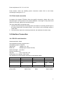
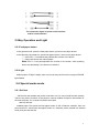
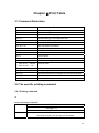
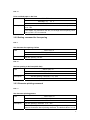
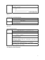
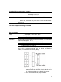
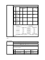
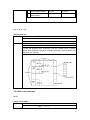
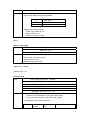
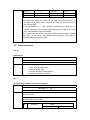
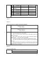
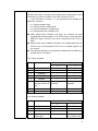
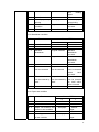
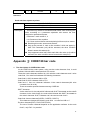
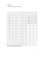
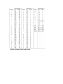
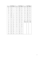
USER’S
MANUAL
ICOD
FTP 628A
Shenzhen ICOD Digital Co., Ltd.
1
DECLARE
§ The content of this document limited to free change without permission,
Shenzhen ICOD Digital Co., Ltd. reserves the right to improve products
on software and hardware. If the user needs further information about
products, please contact Shenzhen ICOD Digital Co., Ltd. and authorized
distributors.
§No part of this document may be reproduced or transmitted in any form
or by any means, without the written permission of Shenzhen ICOD
Digital Co., Ltd.
COPYRIGHT
----- This document made by 2006
----- Copyright: belongs to Shenzhen ICOD Digital Co., Ltd.
----- Edition: 1.0 <2006.12>
2
Security Information
In order to use your printer in effectiveness and security, Please obey the
following rules.
→Before Use
● In order to hold the right use method, before using printer, please
read this user’s manual particularly.
● Please put this 《User’s Manual》on the convenient position, In order
to take out reading and solving problems at any moment.
→Notes In Security
If neglect the following notice matters, incorrect use may be bring
damage.
NOTES
◇ Please don’t set this product in the humid or dusty environment.
◇ No pressing, No dumping.
◇ Do not impose the electric current and voltage over the biggest
absolute fixed value on any pin, If over the normal voltage or the
electric current, the equipment will be brought heat damage.
◇ Make sure that the connection equipment uses the specific cables,
Incorrect connection should be brought losing fire or striking fire.
◇ Any electric material prohibited to fall on the circuit board, the pin on
the short circuit board may be bring heat damage because of the
over electric current.
3
TABLE OF CONTENTS
Chapter Ⅰ Introduction ..................................................................................................... 6
1.1 Technique Specification........................................................................................ 6
1.2 Printing Character ................................................................................................ 6
1.3 Interface Form...................................................................................................... 6
1.4 Control Command................................................................................................ 6
1.5 Power and Operating Environment Request........................................................ 7
1.6 Dimension and Weight(the host control board) .................................................... 7
Chapter Ⅱ Installation and Operation ............................................................................... 8
2.1 General Structure................................................................................................. 8
2.2 PCB Installation Method....................................................................................... 9
2.3 System Installation and Operation ....................................................................... 9
2.3.1 Power connection ...................................................................................... 9
2.3.2 Print head connection .............................................................................. 10
2.4 Interface Connection.......................................................................................... 10
2.4.1 RS-232 serial interface ............................................................................ 10
2.5Key Operation and Light ......................................................................................11
2.5.1Feed paper button......................................................................................11
2.5.2Light ...........................................................................................................11
2.6 Special working mode .........................................................................................11
2.6.1 Self-test.....................................................................................................11
Chapter Ⅲ Print Table..................................................................................................... 12
3.1 Command Illustration ......................................................................................... 12
3.2 The specific printing command .......................................................................... 12
3.2.1 Printing command .................................................................................... 12
LF .............................................................................................................. 12
ESC J n ..................................................................................................... 13
3.2.2 Setting command for line spacing ............................................................ 13
ESC 2 ........................................................................................................ 13
ESC 3 n ..................................................................................................... 13
3.2.3 Character printing command.................................................................... 13
ESC ! n ...................................................................................................... 13
ESC % n .................................................................................................... 14
ESC & s n m .............................................................................................. 14
3.2.4 Special Control Command ....................................................................... 14
ESC c 5 n .................................................................................................. 15
3.2.5 Dot Graphics Printing Command ............................................................. 15
ESC * m n1 n2 d1......dk ............................................................................ 15
GS / n ........................................................................................................ 16
GS * n1 n2 d1......dk .................................................................................. 17
3.2.6 Bar code command.................................................................................. 17
4
GS w n....................................................................................................... 17
GS h n ....................................................................................................... 18
GS k m d1......dk NUL................................................................................ 18
GS k m n d1......dn..................................................................................... 18
3.2.7 Other commands ..................................................................................... 20
ESC @....................................................................................................... 20
ESC v ........................................................................................................ 20
GS V m ...................................................................................................... 21
GS V m n ................................................................................................... 21
DLE EOT n ................................................................................................ 21
DLE ENQ n................................................................................................ 24
Appendix Ⅰ: CODE128 bar code ................................................................................... 24
5
Chapter Ⅰ Introduction
1.1 Technique Specification
Note: At present FTP 628A only supports FTP-628MCL354 print head, the
parameter in the following table measured only on the condition of using this print head.
Item
Parameter
Supporting Print Head
FTP-628MCL354
Printing Mode
Thermal line printing
Printing Speed
50 ㎜/second
Printing Width
57.5±0.5 ㎜
Printing Density
8dot/㎜, 384dot/line
Effective Printing Width
48 ㎜
Paper Solve Method
Auto cut
Detestation of Without Paper
Photo electricity Sensor
Life of Print Head
50KM
Life of Auto cutter
300000
1.2 Printing Character
Item
Parameter
ANK Print font
12×24dot, 1.2(width)×3.00(height)㎜
International Standard Ⅰ
﹑ⅡClass Chinese font
24×24dot
3.00(width) ×3.00(height)㎜
1.3 Interface Form
Item
Serial Interface
Parameter
Support RTS/CTS; Baud rate: 9600bps
Data-base: 1 start bit +8 data bits +1 bit or more than 1 stop
bit
1.4 Control Command
6
Item
Parameter
Dot Printing Command
Support different density dot and load graphics printing
Character
Command
Support ANK character, user defined character and Chinese
characters double width printing, double height printing, the
gap of the characters are adjustable
Printing
1.5 Power and Operating Environment Request
Item
Parameter
Power Supply
DC7.5V~8.5V, 3A
Operating Temp.
0~55
Operating
Humidity
Relative
10~80%
Storage Temp.
-25~70℃
Storage Relative Humidity
0~90%
1.6 Dimension and Weight (control board)
Item
Parameter
Length
100 ㎜
Width
70 ㎜
Height
13 ㎜
Weight
34g
7
Chapter Ⅱ Installation and Operation
2.1 General Structure
Figure 2.1.1 control board
8
Figure 2.1.2 Connecting board
2.2 PCB Installation Method
In order to install FTB628A control board on the case, the designable case must be met
the following requirements.
● Between the above of electrolytic condenser which on the FTB628A1 control board and
case, be sure there are 3 ㎜ or more space.
● Be sure the installation pin of FTB628A have 5 ㎜ or more space, the figure as
follows:
● Fix the FTB628A control board on the mental case.
2.3 System Installation and Operation
2.3.1 Power connection
9
Power requirement: DV 7.5V~8.5V 3A
Power Socket: There are installing power connection socket CN4 on the board,
connecting as the figure of 2.1.1.
2.3.2 Print head connection
At present only support FTP628A, About the specific connection, please refer to the
structural figure. At the process of the actual installation, if the length of the printer head
cable is not enough, please use connection board.
The using steps about connecting board
1. Connect control board with connecting board, the socket of connecting board 30 pin is
the printer head cable connecting socket, 4 pin socket is the connecting socket of
cutter cable.
2. Connect printer head with connecting board well, the method as the above step.
2.4 Interface Connection
2.4.1 RS-232 serial interface
Data transmission: Serial
Synchronization manner: Asynchronous
Handshaking signal: CTS/RTS
Signal level:
MARK=-3 to -15V
Baud rate:
9600bps (bps: bits per second)
Date word length: 8 bit fixed
Check-out manner: No
Stop bits:
1 bit or more than 1 bit
Socket (side of the printer): 4Pin socket
The assignments of the interface socket pin as the following table:
Pin
Signal Name
Signal Source
Illustration
1
TXD
Printer
Transmit data
2
RTS
The host computer
Receive data
3
DTR
Printer
Could
data
4
GND
Connecting with PC as the following figure:
(Printer)DB4
IBMPC DB9
---------DB25
receive
Logically
IBMPC DB25
10
The connection figure of printer serial interface
and PC serial interface
2.5Key Operation and Light
2.5.1Feed paper button
In the general mode, press the feed paper button, printer moves paper ahead.
In the following circumstances, press feed paper button, it won’t move paper ahead.
① Uses ESC c 5 command and prohibits the function of the button.
② Paper-end sensor test without paper.
Note: ESC c 5 can permit/prohibit the function of the button, when pressing
button and prohibiting it, the button is ineffective.
2.5.2Light
Without paper, PE light is bright, when occur over temp and incorrect cut paper, ERROR
light flashed.
2.6 Special worke mode
2.6.1 Self-test
Self-test can test whether the printer is normal or not, If it can print self-test list correctly,
That’s to say, all the functions of the printer in normal condition except for the interface of
the host computer. Or, it needs to examine and repair.
Start-up self-test:
Installed paper, First press the feed paper button on the off-electric condition, then turn
power button on, and loosen feed paper button in 5 seconds, printer entered into self-test
mode, and print self-test list.
11
Chapter Ⅲ Print Table
3.1 Command Illustration
Command
Illustration
LF
Print and change a new line
ESC J n
Print and feed paper n dot lines
ESC 2 n
Set character line spacing 1/6 feet
ESC 3 n
Set line spacing n dot lines(n/203 feet)
ESC ! n
Set character printing method
ESC % n
Permit/prohibit user-defined character
ESC & s n m
Set user-defined character
ESC c 5 n
Permit/prohibit pressing button command
ESC * m n1 n2 d1......dk
Set dot command
ESC * n1 n2 d1......dk
Defined load dot
GS / n
Print load dot
GS w n
Set bar code width
GS h n
Set bar code height
① GS k m d1......dk NUL
② GS k m n d1......dn
Print bar code
ESC @
Initialization
ESC v
Send printing status to the host computer
ESC v m
Choose the method of cut paper and cut and send paper
DLE EOT n
Transmit real-time status
DLE ENQ n
Send real-time request to printer
3.2 The specific printing command
3.2.1 Printing command
LF
Print and change a new line
Form
ASCⅡ: LF
DECIMAL: 10
HEX:
Description
0A
Printing content in the line buffer and move one paper line ahead, when
line buffer is empty, only moving one line ahead
12
ESC J n
Print and feed paper n dot lines
ASCII: ESC
form
DECIMAL: 27
HEX: 1B
Description
J
n
74
n
4A n
Printing content in the line buffer and move n dot lines ahead(n/203feet)
n=0~255
This orders only effected to this line, not change the line spacing which
set by ESC 2, ES 3 command
3.2.2 Setting command for line spacing
ESC 2
Set character line spacing 1/6 feet
ASCII: ESC 2
Form
DECIMAL: 27 50
HEX: 1B 32
Set line spacing 1/6 feet
ESC 3 n
Set line spacing n dot lines(n/203 feet)
ASCII: ESC 3 n
Form
DECIMAL: 27 51 n
HEX: 1B 33 n
Description
Set line spacing n dot lines. n =0~255
This orders set line spacing n/203 feet. Default value: n=30
3.2.3 Character printing command
ESC ! n
Set character printing pattern
Form
ASCII: ESC ! n
DECIMAL: 27 33 n
HEX: 1B 21 n
Description
Set line spacing n dot lines. n =0~255
ESC ! n is a comprehensive character printing pattern setting orders, be
used to choose the size of printing character. The default value of n is 0,
13
that’s to say, character isn’t be extended. The definition of per printing
parameter n as follows:
1: Double height printing
1: Double height printing
ESC % n
Permit/prohibit user-defined character
ASCII: ESC % n
Form
DECIMAL: 27 37 n
HEX: 1B 25 n
Description
When n =1, choose user-defined character fond; when n =0, choose
interior character fond
Default value n =0
ESC & s n m
Set user-defined character
Form
Description
ASCII: ESC & S n m 〔a〔p〕s×a〕m-n+1
DECIMAL: 27 38 S n m
〔a〔p〕s×a〕m-n+1
HEX: 1B 26 S n m
〔a〔p〕s×a〕m-n+1
ESC & be used to define user-defined character. S=3, 32≤n≤m≤126
0≤a≤12,
0≤p≤255.
s means the vertical bits, here s=3, n means the started ASCII code of
user-defined character
m means the end ASCII code of user-defined character, when only
defining one character, takes n=m, could define at the most of 96
user-defined character
a means level dot counts; p means user-defined character data, per
character s×a bytes, together defined m-n+1 characters.
After defining, the user-defined character always effects, till defining
again or reposition or turn off print.
3.2.4 Special Control Command
14
ESC c 5 n
Permit/prohibit pressing button command
ASCII: ESC c 5 n
Form
DECIMAL: 27 99 53 n
HEX: 1B 63 35 n
Description
When n=1, prohibit that the paper carrier button effects
When n=0, permit that the paper carrier button effects, Default
value is n=o
3.2.5 Dot Graphics Printing Command
ESC * m n1 n2 d1......dk
Set dot command
Form
ASCII: ESC * m n n1 n2 〔d〕k
DECIMAL: 27 42 m n n1 n2 〔d〕k
HEX: 1B 2A m n n1 n2 〔d〕k
Description
Set dot graphics pattern(takes m), dot counts(takes n1,n2) and dot
graphics content (takes 〔d〕k)
m=0, 1, 32, 33. n1=0~255, n2=0~3. d=0~255
K=n1+256×n2(m=0,1); k=(n1+6×n2) ×3(m=32,33)
Level dot counts is n1+256×n2
If the dot counts over one line, the part which over the biggest dot
count will be neglected(connected with the chosen dot graphics
pattern, the specifics as the following table)
□ d is dot graphics data byte, relevant dot is 1, which
means that this dot should be printed; relevant dot is
0, which means that this dot shouldn’t be printed.
□ m be used to choose dot graphics pattern.
15
M
Vertical
Mode
Horizontal
Dot
coun
t
Dot
density
Dot density
The most
of
dot
counts
0
8
dot
single
density
8
68 DPI
101 DPI
192
1
8
dot
double
density
8
68 DPI
203 DPI
384
32
24
dot
single
density
24
203 DPI
101DPI
192
33
24
dot
double
density
24
203 DPI
203DPI
384
8 dot pattern
24 dot pattern
Dot graphics data(bit graphic)
graphic)
Dot graphics data(bit
GS / n
Print load dot
ASCII:
Form
Description
GS
/
DECIMAL:
29
47
DEX:
1D
2F
n
n
n
This orders be used to print load dot. n=0~3
n be used to choose dot graphics pattern: could use GS * command
to define dot graphics
n
Dot graphics pattern
Veridical density
Horizontal
density
0
Normal pattern
203 DPI
203 DPI
1
Double width pattern
203 DPI
101 DPI
16
2
Double height pattern
101 DPI
203 DPI
3
Double height
width pattern
101 DPI
101 DPI
and
GS * n1 n2 d1......dk
Defined load dot
ASCII: GS
Form
DECIMAL: 29
HEX: 1D
Descriptio
n
*
n1 n2 〔d〕k
42
n1 n2 〔d〕k
2A n1 n2 〔d〕k
This orders be used to define load dot
n 1=1~48, n2=1~255, n1×n2<1200, k=n1×n2×8
d is the dot graphics data; horizontal n1×8 dot; vertical n2×8; It always
effects after loading dot graphics definition until taking new definition and
reposition and recovery
3.2.6 Bar code command
GS w n
Set bar code width
Form
ASCII:
GS w
HEX:
77 n
n
17
DECIMAL:
Descriptio
n
29 119
n
□ Set bar code horizontal size, 2≤n≤3
□ n be set the width of bar code as follows:
N
Bar code
2
Normal
3
Wide bar code
□ Support the below bar code:
CODE 128, CODE 39, ITF
Default value is n =2
Relevant command: GS K
GS h n
Set bar code height
ASCII:
Form
GS h
HEX : 1D
DECIMAL :
Descriptio
n
n
68
n
29 104
n
□ Set bar code height, 1≤n≤255;
□ n be set the vertical dot counts
□ Default value is n=50
□ Relevant command: GS K
○1 GS k m d1......dk NUL
○2 GS k m n d1......dn
Print bar code
①ASCII code: GS k m d1......dk NUL
Form
HEX: 1D 6B m d1......dk
00
DECIMAL: 29 107 m d1.......dk 0
②ASCII code: GS k m n d1......dn
HEX: 1D 6B m n d1......dn
DECIMAL: 29 107 m n d1......dn
Descriptio
n
□ Choose bar code system and print bar code:
① 4≤m≤5 (k and d decided by using bar code system)
② m=73 (n and d decided by using bar code system)
□ m set the bar code system as follows:
M
Bar
code
system
Character
units
Notes
18
①
②
4
CODE39
1≤K
48≤d≤57,
65≤d≤90,32,36,37,43,45,
46,47
5
ITF
1≤K(k is even)
48≤d≤57
73
CODE128
1≤n≤255
0≤d≤127
【Note①】
·This orders finished by NUL code.
·The units of ITF bar code data must be even. When inputting odd units
data, the printer will be neglected the last one which received.
【Note②】
·n designates bar code data byte counts, and the printer will take n byte
date and deal with as the bar code data from the next character.
·If n exceeds the designated scale, then the printer stop dealing with this
orders, and treat continued data as the general data.
·This orders feed paper according to the requirement of printing bar code,
no consider the line spacing which set by ESC 2 or ESC 3.
·This orders only effects that there are no data in the printing line buffer
area. When there are data in the printing line buffer area, the printer will
treat continued data as the general data.
·After printing bar code, this orders set the printing position at the beginning
of a line.
·This orders no effected by printing pattern(the size of character and so on),
except reverse printing pattern.
When using CODE128(m=73):
·About the information of CODE128 bar code and code table, please
consult appendix Ⅰ.
·When this printer uses CODE128, please consider the below factors which
refers to sending the data:
① The head of bar code data must be the chosen character(CODE
A,CODE B, or CODE C) of code fond, be used to choose the first
used code fond.
② Defined special characters by used “{” and a group of characters,
Through sending two “{” definition continually and defined ASCII
character “{”.
Special
character
Sending data
ASCII code
HEX
DECIMAL
SHIFT
{ S
7B, 53
123, 83
CODE A
{ A
7B, 41
123, 65
CODE B
{ B
7B, 42
123, 66
CODE C
{ C
7B, 43
123, 67
FNC 1
{1
7B, 31
123, 49
FNC 2
{2
7B, 32
123, 50
19
FNC 3
{3
7B, 33
123, 51
FNC 4
{4
7B, 34
123, 52
7B, 7B,
123, 123
“{”
{
{
·If the data serial head of bar code is not the code fond chosen character, so
the printer stop dealing with command, and treat the continued data as
the general data.
·If the combination of “{” and continued characters isn’t fitting for any
special characters, so the printer stop dealing with command, and treat
the continued data as the general data.
·If the printer can’t receive the characters which should be used to special
code fond, so the printer stop dealing with command, and treat the
continued data as the general data.
3.2.7 Other commands
ESC @
Initialization
ASCII: ESC @
Form
DECIMAL: 27 64
HEX: 1B 40
Descriptio
n
ESC @ command initializes the following contents:
□ Clear away printing buffer;
□ Restore default value;
□ Choose character printing pattern;
□ Delete user-defined character.
ESC v
Send printing condition to the host computer
ASCII: ESC
Form
v
DECIMAL: 27 118
HEX: 1B
Descriptio
n
76
Send printing condition to the host computer, only effects serial
communication.
When the printer received this orders, sending one byte up to printer
through serial interface TXD.
The definition of per byte as follows:
Bit
Data
Function
0
1
20
0
Undefined
----------
----------
1
Undefined
----------
----------
2
Paper-test
machine
With paper
Without paper
----------
----------
3
Undefined
4
Unused
5
Undefined
----------
---------
6
Undefined
----------
---------
7
Undefined
----------
---------
Identical data is 0
Identical data is 0
○1 GS V m
○2 GS V m n
Choose the pattern of cut paper and cut and send paper
ASCII: GS V m
DECIMAL: 29 86 m
HEX: 1D 56 m
Form
ASCII: GS V m n
DECIMAL: 29 86 m n
HEX: 1D 56 m n
Descriptio
n
0≤n≤255
This orders supports two cutting pattern
When m=0,1,48,49, printer executes direct cutting paper pattern.(Full
cutter or half cutter)
When m=66, printer firstly moves the paper ahead(The position of
cut/slice paper + n×0.176 ㎜), then cutting paper.
·Execute full cut paper or half cut paper which determined by DIP set.
·This orders only effects when the printing position set at the beginning
of the line.
·When chosen black mark is effective, It’s ineffective when execution GS
v 66 command, the space of feeding paper ahead which determined by the
parameter of GS ( F command.
DLE EOT n
Transmit real-time status
Form
ASCⅡ: DLE EOT n
DECIMAL: 16
4
HEX: 10 04
n
n
21
Description
This orders only supports the D5000 serial interface model, after
receiving this order, according to the requirement of parameter n, send
a relevant byte printer condition to the host computer at once.
n took the scale of number 1~4, the relevant printer condition for
different n number is:
n=1: Printer condition byte
n=2: Printer off-line condition byte
n=3: Printer breakdown condition byte
n=4: Printer paper test condition byte
● When printer send condition byte back, not consider the host
computer allow sending date or not, That’s to say, not test interface
DSR/CTS signal, send at once when receiving the DLE EOT n
order.
● When printer send condition byte back, not consider printer line is
off-line or not, receiving buffer is full or not, or whether happen any
one of fault.
● The specified definition of the relevant condition byte for different n
number as the next tables.
n=1: Printer condition
Bit
Function
Datum OFF/ON
0
1
0
Unused
0
---
1
Unused
---
1
2
Undefined
---
---
3
4
5
Off-line/On-line
On-line
Unused
---
Whether
waiting
on-line restored or
not
6
Undefined
7
Unused
Off-line
1
Not waiting on-line
restored
Waiting on-line
restored
---
--0
---
n=2: Off-line condition
Bit
Function
Datum OFF/ON
0
1
0
Unused
0
---
1
Unused
---
1
2
Undefined
---
---
3
Press key
feed paper
and
No feed paper
The processing
of pressing key
22
and
paper
4
Unused
5
Out of paper stop
printing
6
In
breakdown
condition
In good condition
7
Unused
0
feeding
---
1
With paper
Without
paper
stop printing
Breakdown
occurred
---
n=3: Breakdown condition
Bit
Function
Datum OFF/ON
0
1
0
Unused
0
---
1
Unused
---
1
2
Machine
breakdown
In good condition
Machine
breakdown
occurred
3
Cutter breakdown
In good condition
Cutter
breakdown
occurred
4
Unused
---
1
5
The
breakdown
can’t be restored
Any
breakdown
can be restored
The breakdown
can’t be restored
which
have
occurred
6
The
breakdown
can be restored by
itself
Any
breakdown
can be restored by
itself
The breakdown
can be restored
by itself which
have occurred
7
Unused
0
---
n=4: Paper test condition
Bit
Function
Datum OFF/ON
0
1
0
Unused
0
---
1
Unused
---
1
2.3
4
5.6
Paper will exhaust and
switch in test condition
Unused
Out of paper and switch
in test condition
With paper
--With paper
Without
paper
1
Without
paper
23
7
Unused
0
---
DLE ENQ n
Send real-time request to printer
Form
ASCⅡ: DLE ENQ n
DECIMAL: 16
HEX: 10
Description
5
05
n
n
This order only effects to the D5000 serial model, when receiving this
order, according to n parameter stipulation and answer the host
computer’s operational request.
Parameter n took number 0, 2
n=0: Restore on-line condition
n=2: Clear received buffer area and printing buffer area, then restart.
● Receiving this order, answer and execute.
● Only at the process of “wait on-line condition” which set paper by
itself. This command (n=0) will be executed, the other condition
doesn’t answer this order(n=0).
● Only happened cutter fault, black mark fault, this order (n=2) will be
executed, the other condition doesn’t answer this order(n=2).
Appendix Ⅰ: CODE128 bar code
1. The description of CODE128 bar code
At the CODE128 bar code system, using one bar code character fond, it could
indicate 128 units ASCII characters and 2 bit counts.
These bar code characters defined by 103 units bar code characters and 3 units
code fond , Per code fond indicates the following characters:
·Code fond A: ASCII character 00H to 5FH
·Code fond B: ASCII character 20H to 7FH
·Code fond C: Use one character indicates 2 bits natural characters(100 units
numerals from 00 to 99)
There are another special characters among CODE128:
·SHIFT character
At the code fond A, the code which followed with SHIFT be treated as the code B
character. At the code fond B, the code which followed with SHIFT be treated as
the code A character. SHIFT character can’t be used at code fond C.
·Code fond chosen character(CODE A, CODE B, CODE C)
This character changes the following code fond to code fond A B or C
·Function character(FNC1, FNC2,FNC3,FNC4)
The use of function character depends on the application software. At the code
fond C, only FNC 1 in practical.
24
Code table
Printing character among code fond A
Printing character among code fond B
25
Printing character among code fond C
26
27