1
MBT 250 SYSTEMS
OPERATION &
MAINTENANCE
MANUAL
1
GENERAL INFORMATION
Use of this manual
The information contained in this manual will provide the user with the knowledge necessary to
properly operate and maintain the PACE MBT 250 systems. When using your new system in
standard soldering/desoldering operations, you can begin operation quickly by performing the
"Set-Up" and "Quick Start - Basic Operation" procedures detailed on pages 13-19 of this manual.
To fully utilize the features of the system, PACE Strongly recommends that the user read and fully
understand the "Operation" and "Calibration" portions of this manual. The use of these features
is especially important when performing operations which require the use of large or specialized
tips. The "Quick Reference" guide is provided as a convenient reference for day-to-day operation
of the system.
If you encounter any difficulty operating your system, call your local authorized PACE dealer or
contact PACE as shown on page iv of this manual.
1
GENERAL INFORMATION
Introduction
MBT 250 Universal Soldering and Repair Systems provide the user with the power and versatility to remove and
install virtually all SMD and Thru-Hole components. The power source incorporates the highly responsive
SensaTemp (closed-loop) temperature control system which provides up to 182 watts of total power to the three
output channels (see Power Management, Page 12). Microprocessor controlled circuitry allows the user to quickly
configure the system to their requirements and easily recalibrate the system to maintain accuracy and peak
performance. Accessory SensaTemp handpieces (standard & optional) and a wide variety of special use tips,
employing different shapes and sizes, allow the user to remove and replace a wide variety of component
configurations.
Virtually all of today’s specialized handpieces with large SMD tips suffer from a problem in which the actual tip
temperature that the work sees can be more than 55°C (100°F) cooler than the Set Tip Temperature displayed. The
MBT 250 systems feature PACE’s unique Tip & Temperature Selection System with Auto Tip Offset Compensation
which allows the user to Set and Display the True, Correct Tip Temperature for any size and type of tip or
handpiece.
The MBT 250 systems are available in either the 115 VAC, 100 VAC or 230 VAC versions. The 230 VAC version
systems bear the CE Conformity Marking which assures the user that it conforms to all the requirements of council
directive EMC 89/336/EEC. The systems include the power source with a selection of accessories and functional
aids.
PACE uses the following suffix letters on all MBT 250 systems to indicate the specific design configuration.
S - Soldering (PS-90)
D - Desoldering (SX-80)
T - Thermotweez (TT-65)
J-
ThermoJet (TJ-70)
P - ThermoPic (TP-65)
2
GENERAL INFORMATION
Power Source, 115 VAC, 60 Hz
X
Power Source, 230 VAC 50 Hz
MBT 250E-SDPT Soft Ground
MBT 250E-SDPT
MBT 250-SDPT
MBT 250E-SD Soft Ground
MBT 250E-SD
MBT 250-SD
System Configurations
X
X
X
X
X
X
X
X
SX-80 Sodr-X-Tractor
X
X
X
X
X
X
TP-65 ThermoPic Handpiece
X
X
X
TT-65 ThermoTweez Handpiece
X
X
X
X
X
X
X
X
SX-80 Tip and Tool Stand
X
X
X
X
X
X
Tip Maintenance Station
X
X
X
X
X
X
Pace Tip & Tempurature Selection System Kit
X
X
X
X
X
X
System Part Number
8007-0206
X
8007-0203
PS-90 Tip and Tool Stand
8007-0207-1
X
8007-0207
X
8007-0204-01
X
8007-0204
PS-90 Soldering Iron
3
GENERAL INFORMATION
SPECIFICATIONS
POWER REQUIREMENTS
MBT 250 -
Version operates on 97-127 VAC, 50/60 Hz.
185 Watts, 1.6 Amp max, 100% Duty Cycle, Motor on.
MBT 250E -
Version operates on 196-253 VAC, 50 Hz.
212 Watts, 0.92 Amp max, 100% Duty Cycle, Motor on.
PHYSICAL PARAMETERS
Size:
13.5 cm H x 16.5 cm W x 26 cm D (5.3"H x 6.5"W x 10.25"D)
Weight:
4.5 Kg. (10 Lbs.)
VACUUM AND AIR (motor operated systems)
Measurements at front panel AUTO SNAP-VAC and CONTROLLABLE PRESSURE Ports.
Vacuum Rise Time:
Evacuates 33 cc (2 cubic inch) volume
to 25 cm Hg. (10 in. Hg.) in 150 ms.
Vacuum:
51 cm Hg. (20 in. Hg.) (nominal)
Pressure:
.48 Bar (7 P.S.I.) (nominal MAXIMUM setting)
Air Flow:
9 SLPM (0.32 SCFM)MAXIMUM
TEMPERATURE SPECIFICATIONS
4
Tip Temperature Range:
38°C to 482°C (100°F to 900°F) nominal (see note).
Digital Readout Resolution:
±1° (°C or °F)
Tip Temperature Stability:
±1.1°C (2°F) at Idle from Set Tip Temperature.
GENERAL INFORMATION
NOTE
Actual minimum and maximum Operating Tip Temperatures may vary
depending on handpiece & tip selection.
EOS/ESD
Tip-To-Ground Resistance:
Less than 5 ohms (except on Soft Ground Systems).
AC Leakage:
Less than 2 millivolts RMS from 50Hz to 500Hz
(except on Soft Ground Systems).
ENVIRONMENTAL REQUIREMENTS
Ambient Operating Temperature: 0°C to 50°C (32°F to 120°F)
Storage Temperature:
-40°C to 100°C (-40°F to 212°F)
Capabilities
All capabilities are dependent upon the use of the appropriate Functional Accessories or Work Aids (refer to Basic
Operation section). Available SensaTemp handpieces and their associated assembly and repair functions are listed
below. An Operations and Maintenance Manual is provided separately with each handpiece which describes the
applications and recommended procedures for that particular tool.
PS-90 Soldering Iron - Provides a wide range of SMD and thru-hole installation and removal capability as well as
unsurpassed thermal performance on heavy, multilayer thru-hole assemblies at safe, lower working temperatures.
A wide variety of 3/16" shank, quick change thru-hole and SMD tips (for chip components, SOTs, SOICs and
other components) are available.
SX-80 Sodr-X-Tractor handpiece - Air handpiece ideal for thru-hole desoldering on extra high mass multilayer
boards. Also ideal for removal of TSOP & TQFP surface mount components and for “Flo” desoldering during
surface mount land preparation.
TT-65 ThermoTweez handpiece - Performs removal of PLCC (J Leaded), LCCC (leadless) and other surface mount
devices.
TP-65 ThermoPik handpiece - Air handpiece performs removal of Flat Pack, QFP & PQFP surface mount devices.
DTP-80 Dual ThermoPik handpiece - Air handpiece performs removal of large Flat Pack, QFP, PQFP & BGA surface
mount devices.
TJ-70 Mini ThermoJet handpiece - Air handpiece. Focused hot air reflow handpiece used for installation of all
types of surface mount devices.
5
GENERAL INFORMATION
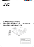
Parts Identification
Listed below is a description of the system power source parts. Use Figures 1 & 2 as a guide.
1. CH 1 POWER RECEPTACLE - Provides power, tip ground, sensing circuitry and finger switch connection
from MBT system to handpiece connected to Channel 1 (CH 1).
2. CH 2 POWER RECEPTACLE - Provides power, tip ground, sensing circuitry and finger switch connection
from MBT system to handpiece connected to Channel 2 (CH 2).
3. CH 3 POWER RECEPTACLE - Provides power, tip ground, sensing circuitry and finger switch connection
from MBT system to handpiece connected to Channel 3 (CH 3).
4. POWER SWITCH - Turns system ON ("1") and OFF ("0"); controls input power to the system.
5. AUTO SNAP-VAC PORT - Quick connect fitting provides quick-rise vacuum for Sodr-X-Tractor,
ThermoPik and Dual ThermoPik handpieces. Vacuum is present when handpiece finger switch or optional
foot pedal is actuated. Vacuum ceases 1.2 seconds after switch (or foot pedal) released.
6. CONTROLLABLE PRESSURE PORT - Quick connect fitting with adjustable valve which provides
variable air flow for Mini ThermoJet handpiece (in Hot Jet Mode) and Sodr-X-Tractor handpiece. Air
pressure is present when handpiece finger switch or optional foot pedal is actuated. Air pressure ceases
1.2 seconds after switch (or foot pedal) is released.
7. DIGITAL READOUT - Provides a three digit display of the Current Channel (channel with illuminated LED;
CH 1, CH 2 or CH 3 ) temperature information. This includes: Operating Tip Temperature in Temperature
Display Mode (normal operation), Tip Offset Constant in Tip Offset Mode, Set Tip Temperature in Tip Set
Mode and other information in Calibration (CAL) Mode.
8. °F /°C KEY - Selects °F or °C display of Set and Operating Tip Temperatures and Tip Offset Constants.
9. °F LED - Illuminates when Set\ Operating Tip Temperatures and Tip Offset Constants are displayed in °F.
10. °C LED - Illuminates when Set\ Operating Tip Temperatures and Tip Offset Constants are displayed in °C.
11. CH 1 LED - Illuminates when Channel 1 (CH 1) is the “Current Channel” i.e., the channel (with connected
handpiece\tip) whose temperature information is displayed on the digital readout.
12. CH 2 LED - Illuminates when Channel 2 (CH 2) is the “Current Channel” i.e., the channel (with connected
handpiece\tip) whose temperature information is displayed on the digital readout.
13. CH 3 LED - Illuminates when Channel 3 (CH 3) is the “Current Channel” i.e., the channel (with connected
handpiece\tip) whose temperature information is displayed on the digital readout.
14. CH SELECT KEY - Selects the Current Channel (among "Active Channels" i.e., those with a connected
handpiece).
15. TIP SET KEY - Allows the operator to adjust the Set Tip Temperature for the handpiece\tip combination
connected to the Current Channel. Places the system in the Tip Set Mode.
6
GENERAL INFORMATION
16. TIP SET LED - Flashes when TIP SET Key is pressed indicating that the system is in Tip Set Mode.
17. TIP OFFSET KEY - Allows the operator to adjust the Tip Offset Constant for the handpiece connected to
the Current Channel. Places the system in the Tip Offset Mode.
18. TIP OFFSET LED - Flashes when TIP OFFSET Key is pressed indicating that the system is in Tip Offset
Mode. Remains illuminated (not flashing) in Temperature Display Mode (normal operating mode) when a
Tip Offset Constant of greater than "3" for °C ("6" for °F) is entered.
19. SCROLL UP KEY - Increases the Set Tip Temperature (in Tip Set Mode) and the Tip Offset Constant (in
Tip Offset Mode) in one, then ten degree increments. Also used in “CAL” (Calibration) Mode.
20. SCROLL DOWN KEY - Decreases the Set Tip Temperature (in Tip Set Mode) and the Tip Offset Constant
(in Tip Offset Mode) in one then ten degree increments. Also used in “CAL” (Calibration) Mode.
21. EARTH GROUND RECEPTACLE - provides positive earth ground to which a ground cable can be
connected from the workpiece or work surface as part of a static control program.
22. TIP & TEMPERATURE SELECTION SYSTEM CHART HOLDER - Holds PACE’s Tip & Temperature
Selection System Charts which enable the operator to accurately set and display the true, correct operating
tip temperature for any handpiece\tip configuration.
23. AC POWER RECEPTACLE / FUSE HOLDER - Receptacle for providing power to the system from AC
outlet through power cord. Also location of Fuse (F1) which protects system from overcurrent conditions.
24. CAL / SET KEY LOCK (optional) - In the "LOCK" position, Set Tip Temperatures and Tip Offset
Constants cannot be changed. In addition, the system cannot be put into "CAL" Mode. In the
"UNLOCK" position, all system functions operate normally.
25. FOOT PEDAL RECEPTACLE - Input for Foot Pedal (optional) which actuates vacuum or pressure to the
air-operated handpieces.
26. AIR HOSE FITTING ("V" systems only) - Fitting for connection of house air supply to power source air
venturi assembly.
26. FUSE - Provides overload protection for system.
7
GENERAL INFORMATION
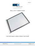
Parts Identification (Con't)
Power
Switch
Earth
Ground
Receptacle
Controllable
Pressure
Port
CH1
Power
Receptacle
AUTO
SNAP-VAC
Port
Digital
Readout
Tip Offset
LED
CH3
Power
Receptacle
CH2
Power
Receptacle
°F LED
CH1 LED
CH2 LED
CH3 LED
°F / °C KEY
Tip Set
LED
°C LED
CH Select Key
Tip Set Key
Tip Offset Key
Figure 1. Parts Identification, Front View
8
Scroll Up Key
Scroll Down Key
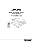
GENERAL INFORMATION
AC Power
Receptacle/
Fuse Holder
CAL/SET
Key Lock
(Optional)
Fuse
Foot
Pedal
Receptacle
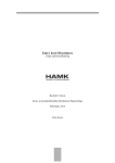
Figure 2. Parts Identification, Rear View
10
9
GENERAL INFORMATION
Power Management
IMPORTANT
POWER MANAGEMENT NOTE
The MBT 250 systems will perform nominally when using any combination of handpieces with a total of 197
Watts or less. When using 2 TT-65 ThermoTweez or DTP-80 Dual ThermoPik handpieces on the system, PACE
recommends that the operator leave the third Power Receptacle vacant to insure optimum performance.
MAX. POWER
1. PS-90 Soldering Iron ..............................................................................51 Watts
2. SX-80 Sodr-X-Tractor handpiece (air handpiece) .................................48 Watts
3. TT-65 ThermoTweez handpiece ............................................................74 Watts (37 Watts each heater)
4. TJ-70 Mini ThermoJet handpiece (air handpiece) .................................75 Watts
5. TP-65 ThermoPik handpiece (air handpiece) .........................................43 Watts
6. DTP-80 Dual ThermoPik handpiece ......................................................74 Watts (37 Watts each heater)
NOTE
Although 2 air handpieces can be powered up and idle at set temperature
simultaneously, only one may have its air hose attached to the unit and operate
at a time. In addition, any other combination of handpieces with a total of 197
Watts or less will perform nominally (add the Wattage designations on the heater
flange(s) of each handpiece to calculate total Watts). For example, you may want
to have two or more PS-90 Soldering Irons with different tips powered up at one
time for convenience.
PACE recommends the purchase of a ST series system power source which can be used in conjunction
with the MBT 250 system. For example, you may want to power a TJ-70 Mini ThermoJet, PS-90 Soldering
Iron and a SX-80 Sodr-X-Tractor handpiece on your MBT 250, and power a TT-65 ThermoTweez handpiece
on your ST-TT system to suit your particular application.
If you require assistance in the use of this product, contact your local authorized PACE dealer or
PACE directly as shown on page iv of this manual.
10
11
SAFETY
The purpose of this "SAFETY" section is to inform users of the heading guidelines used in this manual to indicate
special Notes, Cautions, Warnings or Dangers. Also included are recommended precautions which must be
observed when operating or servicing this product.
Heading Guidelines
PACE adheres to the following Heading Guidelines (based on OSHA guidelines) when listing special information or
precautions to be taken. Especially important are all procedures and practices which, if not strictly observed, could
result in injury or loss of life.
These "NOTES", "CAUTIONS","WARNINGS" and "DANGERS" are inserted in this manual whenever deemed
necessary. They appear in a blocked off form with double outline and a shaded background to highlight the
information as shown below.
NOTE
XXXXXXXXXXXXXXXXXXXXXXXXXXXXXXXXXXXXXXXXXXXXXXXXXX
NOTE
Used to indicate a statement of company recommendation or policy. The message may relate directly or indirectly
to the safety of personnel or protection of property. NOTE is not associated directly with a hazard or hazardous
situation and is not used in place of "CAUTION", "WARNING" or "DANGER".
CAUTION
Used to indicate a hazardous situation which may result in minor or moderate injury. May also be used to alert
personnel to conditions, procedures and practices which, if not observed, could result in damage to or destruction
of the product or other equipment.
WARNING
Used to define additional information that if not closely followed might result in serious damage to equipment and
represent a potential for serious personnel injury.
DANGER
Defines additional information that if not closely followed might result in severe personnel injury or death. Danger
is not used for property damage unless personal injury risk is present.
12
11
SAFETY
Precautions
The following are general safety precautions which personnel must understand and follow when using or servicing
this product. These precautions may or may not be included elsewhere in this manual.
CAUTIONS
1. Handpiece heaters and installed tips are hot when handpiece is powered on. DO NOT touch either the
heater or tip. Severe burns may result! Always store handpiece in the appropriate Tip & Tool Stand
when not in use.
2. Always use this system in a well ventilated area. A fume extraction system such as those available from
PACE are highly recommended to help protect personnel from solder flux fumes.
3. Exercise proper precautions when using materials (e.g., solder paste). Refer to the Material Safety Data
Sheet (MSDS) supplied with each chemical and adhere to all safety precautions recommended by the
manufacturer.
NOTES
Refer to the MBT 250, Service Manual (P/N 5050-0352) whenever service is required.
To insure continued peak performance, use genuine PACE replacement parts.
12
13
SAFETY
Safety Guidelines, English Language
The following are safety precautions which personnel must understand and follow when using or servicing this
product.
1. POTENTIAL SHOCK HAZARD - Repair procedures on PACE products should be performed by
Qualified Service Personnel only. Line voltage parts may be exposed when the equipment is
disassembled. Service personnel must avoid contact with these parts when troubleshooting the
product.
2. To prevent personnel injury, adhere to safety guidelines in accordance with OSHA and other applicable
safety standards.
3. SensaTemp handpiece heaters and installed tips are hot when the handpiece is powered on and for a
period of time after power off. DO NOT touch either the heater or the tip. Severe burns may result.
4. PACE Tip & Tool Stands and handpiece cubbies are designed specifically for use with the associated
handpiece and houses it in a manner which protects the user from accidental burns. Always store the
handpiece in its holder. Be sure to place the handpiece in its holder after use and allow to cool before
storing.
5. Always use PACE systems in a well ventilated area. A fume extraction system such as those available
from PACE are highly recommended to help protect personnel from solder flux fumes.
6. Exercise proper precautions when using chemicals (e.g., solder paste). Refer to the Material Safety Data
Sheet (MSDS) supplied with each chemical and adhere to all safety precautions recommended by the
manufacturer.
Sicherheit Korrekturlinien, Deutsche Sprache
Die nachfolgenden Sicherheitsvorschriften sollten vom Bedien- un Servicepersonal verstanden und befolgt
werden.
1. Entladung spannungsfuehrender Teile - Reparaturen an PACE Produkten sollten nur von qualifizierten
Personal durchgefuehrt werden. Spannungsfuehrende Teile koennen sich bei gezogenen Netzstecker
entladen. Servicepersonal muss den Kontakt dieser Teile vermeiden.
2. Um moegliche Gefahren fuer Personen auszuschliessen, muessen alle Sicherheitsvorschriften in
Uebereinstimmung mit OSHA und anderen anwendbaren Sicherheitsstandards eingehalten werden.
14
13
SAFETY
3. Angeschlossene SensaTemp Heizelemente von Handwerkzeugen und installierte Loetspitzen sind
heiss wenn das System eingeschaltet ist oder erst vor kurzer Zeit ausgeschaltet wurde. Heizelement
und Loetspitze nicht beruehren. Verbrennungsgefahr.
4. PACE Tip & Tool und andere Handwerkzeugablagen sind so konstruiert, dass ein versehentliches
Beruehren des dazugehoerendes Handwerkzeuges vermieden wird. Bewahren Sie das Handwerkzeug
nach Gebrauch stets in der Ablage auf. Bevor das Handwerkzeug an einem anderen Ort gelagert werden
muss, lassen Sie es in der Werkzeugablage vollstaendig abkuehlen.
5. Benutze PACE Systeme nur in gut beluefteten Raeumen. Ein Loetrauchabsaugsystem, wie es z.B. von
PACE erhaeltlich ist, hilft Bedienpersonen von den Gefahren von Loetrauch zu schuetzen.
6. Wenn Chemikalien (z.B.: Lotpaste) verwendet werden, muessen alle die in den Sicherheitsdatenblaettern
des Herstellers ausgewiesenen Sicherheitsvorschriften eingehalten werden.
SICHERHEITDIRECTIVES DE SÉCURITÉ,
Directives de Sécurité, Française Langue
Les précautions suivantes, sont celles que le personnel doit comprendre et suivre lorsqu'il utilise, effectue la
maintenance ou se sert d'un produit PACE.
1. Danger potentiel de choc èlectrique - Les procédures de réparation sur les produits PACE doivent être
effectuées seulement par du personnel qualifié. Des parties de l'équipement désassemblées peuvent
être sous tension. Le personnel de maintenance doit éviter tout contact avec ces parties en réparant le
produit.
2. Pour prévenir tout préjudice, le personnel adhère au guide de sécurité en accord avec OSHA
(équivalent à des normes françaises de sécurité) et d'autres standards de sécurité applicable.
3. La mise sous tension des outils SensaTemp comporte des éléments chauffants (buse). Ces derniers,
gardent la chaleur même après la mise hors tension pendant un certain temps. Ne pas toucher les
parties chaudes aux extrémités des outils. Des brûlures sévères peuvent en résulter.
4. Les outils PACE et leurs pannes ainsi que le support sont dessinés de manière spécifique afin de
protéger l'utilisateur/opérateur de brûlures accidentelles. Reposer toujours les outils après chaque
utilisation dans leurs étuis/supports afin de permettre leur refroidissement.
5. Utiliser toujours les stations Pace dans unlieu bien ventilé. Des extracteurs de fumée Pace sont
hautement recommandés pour protéger votre personnel des vapeurs de soudure/flux.
6. Prenez les mesures nécessaires quand vous utilisez des produits (ex: solder paste) chimiques. Reportezvous au document (fiche technique/sécurité) du fabricant fourni avec chaque produit. Respectez toutes
les procédures de sécurité recommandées par le constructeur.
14
15
SAFETY
Misure di Sicurezza, Italiana Lingua
Le seguenti instruzioni sono misure di sicurezza che il personale deve comprendere e seguire quando utilizza o
ripara I prodotti PACE.
1. EVENTUALI RISCHI DI SHOCK ELETTRICO- Si consiglia di far eseguire le operazioni di riparazione
dei prodotti PACE, da un servizio di personale qualificato. Quando la stazione non é assemblata le parti
sottoposte alla tensione di linea potrebbero essere scoperte. Il personale deve evitare il contatto con
queste parti durante manutenzione del prodotto.
2. Per evitare eventuali pericoli al personale, attenersi alle norme di sicurezza previste dalla guida, in conformitá
all’OSHA e agli altri Standard di Sicurezza applicabili.
3. Le resistenze PACE Sensatemp e le punte installate sono calde quando la stazione é accesa e per un
periodo successivo allo spegnimento. Non toccare la resistenza e la punta. Puó comportare gravi
ustioni.
4. I supporti PACE sono specificamente costruiti insieme alla corrispondente impugnatura e progettati per
un uso che protegge gli utenti da ustioni accidentali. Mettere sempre l’impugnatura nel propio supporto
dopo l’utilizzo e lasciarla raffredare prima di riporla.
5. Utilizzare sempre I stazioni PACE in una zona be aerata per proteggere il personale dai fumi. É fortemente
raccomandato un sistema di aspirazione (dei fumi) come quello disposta dalla PACE.
6. Usare precauzioni quando si utilizzano sotanze chimiche (es. Pasta di stagno). Fare riferimento al
Material Safety Data Sheet (MSDS) fornita con ogni sostanza chimica e seguire tutte le misure di
sicurezza raccomandate dal fabbricante.
16
15
SAFETY
Guidelines de Segurança, Portuguese Lingua
Segeum-se precauções de segurança que os operadores devem compreender e seguir ao utilizar ou reparar
produtos PACE.
1. Perigo de choque eléctrico - Os procedimentos de reparação em produtos PACE, devem ser apenas
efectuados por pessoal qualificado. Linhas de alimentação podem ficar expostas ao desmontar o
equipamento. Pessoal de reparação deve evitar o contacto com essas partes ao reparar o produto.
2. Para evitar danos pessoais, siga as normas de segurança OSHA ou outras normas aplicáveis.
3. Resistencias de aquecimento dos ferros e as pontas instaladas estão quentesquando o ferro está
alimentado, e mesmo durante algum tempo após ser desligado. NUNCA TOCAR nem na resistencia de
aquecimento nem na ponta. Pode resultar em queimaduras severas.
4. Os suportes para pontas e ferros da PACE, foram concebidos para uso especifico, e para proteger o
operador de queimaduras acidentais. Coloque sempre os ferros nos respectivos suportes. Tenha a
certeza de colocar sempre o ferro no respectivo suporte após cada utilização e deixe-o arrefecer antes de
o guardar.
5. Utilize sempre os sistemas da PACE em locais bem ventilados. Um Sistema de extracção de fumos, como os
Sistemas disponiveis na PACE, são altamente recomendados para a protecção dos utilizadores contra os fumos
produzidos pela solda e fluxo.
6. Tenha precauções apropriadas ao utilizar produtos quimicos (ex. pasta de soldar). Lêr sempre atentamente os
normas de segurança fornecidas com cada produto químico e siga sempre todas as precauções de segurança
recomendadas pelo fabricante.
Guias de Consulta de Seguridad, Espãnol Lenguaje
Lo siguiente es precauciones de seguridad que el personal debe entender y debe seguir al usar o reparar productos
de PACE.
1. RIESGO de SHOCK POTENCIAL - Los procedimientos de la Reparación en productos de PACE sólo
deben ser realizados por Personal de Servicio Calificado. Pueden exponerse partes de voltaje de línea
cuando el equipo se desmonta. El personal de servicio debe evitar contacto con estas partes al arreglar el
producto.
2. Para prevenir lesión del personal, adhiera a las reglas de seguridad de acuerdo con OSHA y otras
normas de seguridad aplicables.
16
17
SAFETY
3. Las herramientas SensaTemp tienen sus calentadores y las puntas instaladas calientes cuando la
herramienta esta encendida y por un periodo de tiempo después de apagar el equipo. No toque el
calentador o la punta. Las quemaduras severas pueden resultar.
4. El Soporte de punta y Herramienta PACE se diseñan específicamente para el uso con las herramientas
asociadas y las almacena de una manera que protege al usuario de las quemaduras accidentales.
Siempre guarde la herramienta en su soporte. Esté seguro de poner la herramienta en su soporte
después del uso y permita que la herramienta enfríe antes de guardar.
5. Siempre use sistemas de PACE en una área bien ventilada. Un sistema de extraccíon de humo como
esos disponibles de PACE se recomiendan para ayudar a protejer al personal contra los humos de flujo
de soldadura.
6. Ejercicie las precauciones apropiadas al usar químicos (ej., pasta de la soldadura). Refiérase a la Hoja de Datos de
Seguridad de Material (MSDS) proporcionadó con cada químico y adhiere a todas las precauciones de seguridad
recomendadas por el fabricante.
Säkerhetsföreskrifter, Svenska
Följande säkerhetsföreskrifter måste förstås och följas av personal som använder eller utför service på PACE
produkter.
1. RISK FÖR STRÖMSTÖT - Service / Reparation av PACE produkter får endast utföras av aktoriserad
service personal. Strömförande delar kan kommas åt när produkten är isärplockad. Iaktag aksamhet när
felsökning görs för att undvika strömstötar.
2. För att undvika personskada rekommenderas att OSHA eller andra liknande arbetssäkerhets standarder
följs.
3. SensaTemp verktygselement och installerade spetsar är heta när strömmen är påslagen och en tid efter
att strömmen slagits av. RÖR EJ element eller spets. Risk för brännskador!
4. PACE Spets och Verktygshållare är speciellt utformade för att passa PACE respektive verktyg så att
risken för brännskador kan undvikas. När verktyget ej används bör det alltid förvaras i sin hållare.
5. Tillse att ventilationen är god där PACE System används. Ett lödröksutsug system som t.ex. PACE
tillhandahåller rekommenderas för att skydda användaren för giftig lödrök.
6. Tillse att gällande säkerhetsföreskrifter följs vid användning av kemikalier, t.ex. lodpasta.Se
säkerhetsdatabladen som medföljer kemikalierna och följ de rekommenderade säkerhetsföreskrifterna
från respektive tillverkare. Säkerhetsföreskrifter, Svenska
18
17
SET-UP
System
Set up the MBT 250 system using Figures 3 through 11 and the following steps.
1. Store the shipping container(s) in a convenient location. These containers can be reused to prevent
damage if you ship or store the system.
2. Place POWER Switch in the "OFF" or "0" position.
3. Position the system on a convenient bench.
Figure 3. Power Off
Accessories
4. Assemble Tip & Tool Stands . Attach to the power source if desired. Assembly instructions are
enclosed with each Tip & Tool Stand.
5. Using Figure 4 as a guide, install the Tip & Temperature
Selection System Chart Holder to the top of the power
source.
6. Install the Temperature Selection System booklet onto the
Chart Holder.
7. Place handpieces into the Tip & Tool Stands.
8. Connect handpiece connector plug(s) to power
receptacle(s) CH 1, CH 2 and/or CH 3 in the following
manner.
Figure 4. Chart Holder
a) With the Connector Key end facing the power source, turn the Locking Ring fully counterclockwise.
b) Orient guide on connector with slot of power receptacle.
c) Insert connector into power receptacle.
d) Turn Locking Ring fully clockwise to lock in place.
18
19
SET-UP
9. To avoid confusion among handpieces, PACE recommends
the use of colored cable markers (P/N 6993-0136 Cable
Marker Kit) to identify the particular handpiece . Attach
any two like colored markers, one to each end of the
handpiece power cable or air hose. Select and use a
different colored marker for each handpiece. Labels are also
provided to mark Tip & Tool Stands with the name of the
associated handpiece.
10. If you have purchased an optional foot pedal, insert the
connector plug into the PEDAL Receptacle on the rear
panel of the power source. Install additional handpieces
and accessories as necessary.
Figure 5. Handpiece Connection
11. Plug the prong end of the power cord into a convenient
three wire grounded AC power outlet. The system is now
ready for operation.
12. Read the "OPERATION" section of this manual
thoroughly before operating the system.
Figure 6. Foot Pedal Connection
Handpiece Vacuum/Pressure
The SX-80, TP-65 and DTP-80 handpieces require the use of the AUTO SNAP-VAC (vacuum) Port and the TJ-70
handpiece requires the use of the Controllable PRESSURE Port .
There are two preferred methods for connection of the Air Hose. The advantages of each method are discussed
in the paragraph below. Select the method best suited to your particular application.
1. TRADITIONAL METHOD - Best suited for single air handpiece configurations. Configuration allows
the Air Hose to be attached to the handpiece power cable. Any TJ-70 ThermoJet handpiece should be
configured using this method.
2. QUICK CONNECT METHOD - Best suited for configurations which include multiple air handpiece
attachment. A single Air Hose can be easily transferred between handpieces using quick connect
Fittings attached to the rear of each handpiece.
20
19
SET-UP
Procedures
TRADITIONAL METHOD
1. Connect the 54 inch (137cm) length of Air Hose to the metal
tube in the back of the air handpiece.
2. Insert the ribbed end of a Male Quick Connect Hose Mount
Fitting (P/N 1259-0087) into the free end of the 54 inch (137cm)
Air Hose. Secure the Air Hose to the handpiece power cable
with Cable Clips (P/N 1321-0085-01).
Fitting
Air Hose
Figure 7. Air Hose To Fitting
3. Prepare a VisiFilter in the following manner.
a) Connect a 1 inch (2.5cm) length of clear pvc Air Hose to
each side of the VisiFilter; push and turn hose onto
VisiFilter nipple to seat.
b) To the free end of the air hose connected to the FLOW IN
side of the VisiFilter, insert the ribbed end of a Female Quick
Connect Hose Mount Fitting (P/N 1259-0086).
c) Insert the ribbed end of a Male Quick Connect Hose Mount
Fitting (P/N 1259-0087) in the free end of the air hose
connected to the FLOW OUT side of the VisiFilter.
d) Connect VisiFilter Air Hose (with attached Male Quick
Connect Hose Mount Fitting) to the power source AUTO
SNAP-VAC Port.
Figure 8. VisiFilter Preparation
4. For vacuum, insert Male Quick Connect Hose Mount Fitting connected to long Air Hose into
Female Fitting on 1 inch (2.5cm) Air Hose (connected to VisiFilter). For pressure, insert Male
Quick Connect Hose Mount Fitting directly into the Controllable PRESSURE Port.
CAUTION
When removing any Air Hose, turn and pull. DO NOT attempt to pull Air Hose
directly off. Damage to or breakage of fitting or VisiFilter may occur.
20
21
SET-UP
TRADITIONAL METHOD (CONT'D)
5. Connect the handpiece power cable connector plug to one of
the Power Output Receptacles. For convenience, PACE
recommends the use of CH 3 for air handpieces.
NOTE
If more than one air-operated handpiece is connected
to the power source, insure that only one of the Air
Hoses is connected to either the VisiFilter assembly
(connected to the AUTO SNAP-VAC Port) or the
Controllable PRESSURE Port. Attachment to both
simultaneously will cause a deterioration in
performance.
Figure 9. Handpiece Connection
QUICK CONNECT METHOD
May be used with any handpiece except the TJ-70
ThermoJet.
1. Prepare a VisiFilter in the following manner.
a) Connect a 1 inch (2.5cm) length of clear pvc Air Hose to
each side of the VisiFilter; push and turn hose onto
VisiFilter nipple to seat.
b) To the free end of the Air Hose connected to the FLOW
IN side of the VisiFilter, insert the ribbed end of a Female
Quick Connect Hose Mount Fitting (P/N 1259-0086).
Figure 10. VisiFilter Preparation
c) Insert the ribbed end of a Male Quick Connect Hose
Mount Fitting (P/N 1259-0087) into the free end of the Air
Hose connected to the FLOW OUT side of the VisiFilter.
22
21
SET-UP
2. Insert a Male Quick Connect Hose Mount Fitting (attached to
VisiFilter assembly) into the Female AUTO SNAP-VAC Port on
the front panel of the power source.
3. Attach the ribbed end of a Male Quick Connect Hose Mount
Fitting (P/N 1259-0087) to each end of the 54 inch (137cm)
translucent Air Hose. Push and turn hose onto each Fitting to
seat properly. You may install metal hose clamps (enclosed
with system) to further secure connections.
Air
Hose
Fitting
4. For each air handpiece, attach ribbed end of a Female Quick
Connect Hose Mount Fitting to a 1 inch (2.5cm) length of clear Figure 11. Air Hose To Handpiece
pvc Air Hose; push and turn hoses onto Fittings to seat
properly. You may install a metal hose clamp (enclosed with system) to further secure the connection.
5. Attach the opposite end of the 1 inch (2.5cm) length of clear pvc Air Hose to the metal tube located at
the rear of each handpiece.
6. Connect one end of the long Air Hose (with attached Male Quick Connect Hose Mount Fitting) to the 1
inch (2.5cm) clear pvc Air Hose attached to the rear of the handpiece.
7. For vacuum, insert Male Quick Connect Hose Mount Fitting attached to the remaining end of the long
Air Hose into Female Quick Connect Hose Mount Fitting on 1 inch (2.5cm) clear pvc Air Hose
(connected to VisiFilter). For pressure, insert Male Quick Connect Hose Mount Fitting directly into the
Controllable PRESSURE Port.
8. The long Air Hose may now be easily transferred between air handpieces by removal of Male Quick
Connect Hose Mount Fitting (attached to long Air Hose) from Female Quick Connect Hose Mount
Fitting at rear of air handpiece and attachment to another air handpiece.
CAUTION
When removing any Air Hose, turn and pull. DO NOT attempt to pull Air Hose
directly off. Damage to or breakage of Fitting or VisiFilter may occur.
9. Connect the handpiece power cable connector plugs of each air handpiece to the Power Output
Receptacles.
22
23
Quick Start - Basic Operation
QUICK START - BASIC OPERATION
Introduction
The MBT 250 systems are very easy to operate. As received from the factory, the system can be quickly set up for
use in standard soldering/desoldering operations. Simply perform the following Quick Start Procedure to begin
system operation.
Quick Start Procedure
1. Insure that the Set-Up procedure has been performed; check for the following:
a) VisiFilter connection to the AUTO SNAP-VAC Port on the front panel of the power source.
b) Handpiece cable and air hose connections to the power source.
NOTE
If more than one air-operated handpiece (SX-80, TJ-70, TP-65 or DTP-80) is
connected to the power source, insure that only one of the Air Hoses is connected
to either the VisiFilter assembly (connected to the AUTO SNAP-VAC Port) or the
Controllable PRESSURE Port. Attachment to both simultaneously will cause a
deterioration in performance.
a) All handpiece Tip & Tool Stands set up as desired (using instructions enclosed).
b) Proper tips installed in handpieces.
c) Power cord connection between the house AC supply receptacle and the power source.
2. Turn the Power Switch "On" ("l").
Figure 12. Power On
24
23
Quick Start - Basic Operation
QUICK START - BASIC OPERATION
3. Perform the following to set handpiece tip temperatures.
a) Press the TIP SET Key.
b) Immediately press the Scroll Up (s) Key to increase the desired Tip Temperature. Press the Scroll
Down (t) Key to decrease the Tip Temperature.
c) Press the TIP SET Key.
d) Press the CH SELECT Key to select the next channel with a connected handpiece.
e) Perform steps 3a through 3d until the desired Tip Temperature has been set on all connected
handpieces.
4. Observe the Digital Readout as the Set Tip stabilizes at the desired Tip Temperature. Press the CH
SELECT Key to observe the Tip Temperature of handpieces connected to other channels. The
channel displayed on the Digital Readout is indicated by the illumination of the channel LEDs.
NOTE
Read the "Operation" and "Calibration" sections of this manual to utilize the full
capabilities of the system. This is especially important when using large soldering
tips. Refer to the enclosed handpiece manuals for a complete description
handpiece capabilities.
24
25
Operation
OPERATION
Definitions
Please read and become familiar with each of the following definitions. Each term is used repeatedly in the
following operational procedures to avoid any possible confusion as to the intent of any particular instruction.
ACTIVE CHANNEL - Any channel with a connected handpiece.
AUTOMATIC POWER DOWN - Feature which turns off power to all three channels 90 minutes after all Active
Channels have entered Temperature Setback.
AUTOMATIC TEMPERATURE SETBACK - System feature which, when enabled, will independently set back
each channel’s SET TIP Temperature to 180°C (350°F) after a user selected period of handpiece inactivity (10 to 90
minutes settable in 10 minute increments). This feature is enabled in the “CAL” Mode.
CALIBRATION (CAL) MODE - Mode of operation (indicated by “CAL” on the Digital Readout) in which the
operator can quickly and easily recalibrate the system to insure accuracy and peak performance.
CURRENT CHANNEL - The channel whose temperature information may be set and displayed on the Digital
Readout. The Current Channel is indicated by an illuminated LED next to its designation.
INACTIVE CHANNEL - Any channel without a connected handpiece.
SET TIP TEMPERATURE - Operator selected idle tip temperature entered into the system memory in Tip Set Mode
for handpiece/tip combination connected to Current Channel.
TEMPERATURE DISPLAY MODE - Normal operating mode in which the true operating tip temperature of the
handpiece/tip connected to the Current Channel is displayed on the Digital Readout.
TIP OFFSET CONSTANT - Specific value for a given handpiece/tip combination upon which the system
automatically calculates the correct Tip Temperature Offset at the entered Set Tip Temperature.
TIP TEMPERATURE OFFSET - Temperature value difference between the point in the handpiece heater assembly
at which temperature is sensed and the working end of the attached tip.
TIP OFFSET MODE - Mode of operation in which the Current Channel’s Tip Offset Constant value can be viewed
or altered. In this mode, the Tip Offset LED flashes and the stored value appears on the Digital Readout.
TIP SET Mode - Mode of operation in which the Current Channel’s Set Tip Temperature can be viewed or altered.
In this mode, the Tip Set LED flashes and the stored value appears on the Digital Readout.
OPERATING TIP TEMPERATURE - The true tip temperature at which the handpiece tip operates at any given
time. This temperature is displayed on the Digital Readout in Temperature Display Mode (normal operation) for the
Current Channel.
NOTE
As with any system, Set and Operating Tip Temperatures are only exactly equal
when the handpiece is idling (unloaded at equilibrium) During use, (i.e., under load)
the Operating Tip Temperature will usually be lower.
26
25
Operation
OPERATION
System
POWER UP
1. Ensure that the system is properly prepared for operation. Refer to the "Set-Up" portion of this
manual. The handpieces selected for your application should be connected to the unit. Remember,
PACE recommends connecting any air handpiece (which requires a vacuum hose) to channel number 3
(CH 3). Connect any single vacuum hose to either the AUTO SNAP-VAC Port or Controllable
PRESSURE Port.
2. Turn the POWER Switch ON ("1").
Figure 13. Power On
KEY LOCK FEATURE
3. An optional Key Lock feature is available from PACE which
prevents unauthorized alteration of: Stored Tip
Temperatures, Tip Temperature Offset values, the
Automatic Temperature Setback, Automatic Power Down
and recalibration features. Check the rear panel of the
system power source. If the Key Lock feature is present
there will be a CAL/SET Key Lock switch located in the
upper left portion of the panel. Use the key to turn the
switch to the UNLOCK position. If the feature is not
present, there will, instead, be a round plastic filler plug at
that location.
Figure 14. Key Lock
26
27
Operation
OPERATION
CHANNEL LED OPERATION
4. The Channel LED (CH 1, CH 2 or CH 3) of the first Active Channel encountered by the system (channel
with connected handpiece) will be illuminated. This is the Current Channel. If no channels are active,
"E-1" will be displayed on the Digital Readout and the CH 1 LED will be illuminated.
5. Disconnect the handpiece from the Power Receptacle associated with the Current Channel (e.g., If CH 1
LED is illuminated, disconnect the handpiece connected to CH 1). The unit will now select the next
Active Channel encountered as the Current Channel and illuminate the corresponding LED.
NOTE
If no other Power Receptacles have handpieces attached, the CH 1 LED will be
illuminated and "E-1" will be displayed on the Digital Readout.
6. Reconnect the handpiece removed in step 5.
DIGITAL READOUT OPERATION
7. The Digital Readout provides a 3 digit display of the
Current Channel (CH 1, CH 2 or CH 3) temperature
information. The Digital Readout will show the Set
Tip Temperature in the Tip Temperature Set Mode, Tip
Temperature Offset values in Tip Temperature Offset
Mode and the True Operating Tip Temperature in the
Temperature Display Mode (normal operation).
28
Figure 15. Digital Readout "888"
27
Operation
OPERATION
PANEL CONTROLS
8. With three handpieces connected to the system, press the CH SELECT Key several times to observe
the lighting of the CH 1, CH 2 & CH 3 LEDS. Each subsequent pressing will turn an LED off and turn
the next Active Channel’s LED on. The illumination sequence will be CH 1 to CH 2 to CH 3 and then
back to CH 1. Unplug any one of the handpieces and repeat. The LED of any Inactive Channel (no
attached handpiece) will not light. The next Active Channel in sequence will light.
NOTE
CH 1 LED will illuminate and "E-1" will be displayed
on the Digital Readout if there are no Active Channels.
9. Press the TIP SET Key once. The TIP SET LED will flash and the Digital Readout will display the
stored Set Tip Temperature for the Current Channel. This is TIP Temperature Set Mode. As received
from the factory, the Digital Readout will display "OFF". If no other operation occurs within 5
seconds, the LED will turn off and the Digital Readout will revert to the Temperature Display Mode
(normal operation). Pressing of the TIP SET Key a second time will eliminate the time out period and
immediately place the system in this mode.
10. Press the TIP SET Key once again to enter the Tip Temperature Set Mode. Press and hold the Scroll
Up Key. Observe as the displayed Set Tip Temperature increases first in 1°, then in 10° increments
(°C or °F). Release the key when the Digital Readout reads 316°C (or 600°F). Immediately press the
TIP SET Key once again. Observe the Digital Readout as the Operating Tip Temperature reaches
316°C (or 600°F).
28
29
Operation
OPERATION
PANEL CONTROLS (CONT'D)
11. Press the °F/°C Key several times to observe the alternating illumination of the °F & °C LEDs. Each
subsequent pressing of the key will turn one LED on and the other off. Also notice as the Digital
Readout changes to display the Operating Tip Temperature in °F when the °F LED is illuminated and in
°C when the °C LED is illuminated.
12. Press the TIP SET Key once to enter the Tip Temperature Set Mode. Immediately press & hold the
Scroll Down Key. Observe as the displayed Set Tip Temperature decreases first in 1° and then in 10°
increments (°C or °F). Release the key when the Digital Readout displays 288°C (550°F). Immediately
press the TIP SET Key once again (or wait 6 seconds) and observe the Operating Tip Temperature
decrease to 288°C (550°F).
13. Press the TIP SET Key once again and use the Scroll Up and Scroll Down Keys to enter your desired
SET Tip Temperature. Immediately press the TIP SET Key to exit the Tip Temperature Mode. This
enters the new Set Tip Temperature for the Current Channel (which you’ve already keyed in) into
system memory.
14. Press the TIP OFFSET Key. The TIP OFFSET LED will illuminate and the Digital Readout will display
the Tip Temperature Offset value for the Current Channel. As received from the factory, the Digital
Readout will display "3" FOR °C ("6" FOR °F). If the TIP OFFSET Key is immediately pressed again, or
if no other operation occurs within 5 seconds, the LED will turn off and the Digital Readout will revert to
the Temperature Display Mode (normal operation).
30
29
Operation
OPERATION
NOTE
Refer to "Tip & Temperature Selection" for a complete discussion of Tip Temperature Offset function.
15. Press the TIP OFFSET Key once to enter Tip Temperature Offset Mode. Immediately press and hold
the Scroll Up Key. Observe the displayed Tip Offset Constant increase, first in 1° and then in 10°
increments. Release the Scroll Up Key when the Tip Temperature Offset value reads "33" for °C ("60"
for °F).
16. While still in the Tip Temperature Offset Mode (Tip Offset LED illuminated) press and hold the Scroll
Down Key. Observe the displayed Tip Offset Constant decrease first in 1° and then in 10° increments.
Release the key when the Digital Readout displays "28" for °C ("50" for °F).
17. Immediately press the TIP OFFSET Key to exit the Tip Temperature Offset Mode and enter the new Tip
Offset Constant for the Current Channel into the system memory. Notice that the Tip Offset LED
remains illuminated.
NOTE
Only if a Current Channel has a Tip Offset Constant value greater than the default
("3" for °C or "6" for °F) does this LED remain illuminated.
30
31
Operation
OPERATION
PANEL CONTROLS (CONT’D)
18. The system will retain stored Set Tip Temperatures and Tip Offset Constants even when power is
removed.
19. Note the Current Channel displayed on the system. Turn the POWER Switch to the OFF ("0") position.
Turn the switch back to the ON ("1") position. Using the CH SELECT Key, select the channel displayed
at the beginning of this step.
20. Press the TIP OFFSET Key. Notice that the system has retained the stored Tip Offset Constants. Press
the key once again to exit Tip Temperature Offset Mode.
21. Press the TIP SET Key. Notice that the system has retained the stored Set Tip Temperature in memory.
Immediately press the TIP SET Key once again to exit Tip Temperature Set Mode.
22. In order to prevent a handpiece/tip combination from inadvertently operating at an incorrect Tip
Temperature, the system will not retain a stored Tip Offset Constant if a handpiece is disconnected.
The Tip Temperature Offset will return to the default value of "3" for °C ("6" for °F). Disconnect the
handpiece connected to the Current Channel. Reconnect the handpiece to the same channel. Notice
that the Current Channel changes to the next Active Channel.
23. Press the CH SELECT Key, as necessary, to change the Current Channel to the channel disconnected in
step 22.
24. Press the TIP OFFSET Key. Notice that the Tip Offset Constant has now changed to the default value
of "3" for °C ("6" for °F) and the Tip Offset LED turns off. Whenever a channel becomes inactive, the
system memory automatically reverts to the default.
25. While in Tip Temperature Offset Mode (Tip Offset LED illuminated), use the Scroll Up and Scroll Down
Keys to set Tip Offset Constant values as desired. Press and release the TIP OFFSET Key to exit Tip
Temperature Offset Mode and enter this value into system memory.
32
31
Operation
OPERATION
26. Using the CH SELECT Key, select each Active Channel in sequence, making it the Current Channel
(temperature information displayed on Digital Readout). Using the procedures described in previous
steps 9 thru 17 and step 25 as a reference, enter and store desired Tip Temperature information into
system memory. Refer to the "Tip & Temperature Selection System" booklet sent with your unit and the
Tip & Temperature Selection section of this manual for more detailed information on selection of the
proper tip, handpiece and temperature options for your particular application.
NOTE
The MBT 250 systems embody a "Dynamic Offset" feature which automatically
adjusts the stored TIP OFFSET CONSTANT (stored value is for Tip Offset at 371°C
or 700°F) for any Set Tip Temperature established by the operator. This ensures
the maintenance of true, accurate Tip Temperatures. Simply stated, any operating
Tip Temperature displayed on the digital readout will be correct.
Always set the appropriate TIP OFFSET CONSTANT for the selected handpiece/
tip combination (listed in the shaded area on the Tip & Temperature Selection
System booklet charts) before entering the desired Set Tip Temperature. The Set
Tip Temperature + the Dynamically Adjusted Tip Offset value (usually different
from the entered TIP OFFSET CONSTANT) cannot exceed 489°C (912°F). If this
limit is exceeded, the system will automatically lower the maximum possible Set
(and Operating) Tip Temperature accordingly.
27. If the Key Lock option is present (from step 3), turn
the Key to the "Lock" position. Notice that no
changes in Set Tip Temperature or Tip Offset
Constants are possible with the Key Lock in this
position thereby preventing any unauthorized
alteration of settings.
Figure 16. Key Lock Option
32
33
Operation
OPERATION
Factory Settings
The MBT 250 systems come equipped with a number of features which may be adjusted, enabled or disabled as
desired by the user. Listed below are the features and factory settings of each. To change and/or learn about any
of these features, refer to the applicable part of the "Calibration" section of this manual.
FEATURE
FACTORY SETTING
SYSTEM FEATURES
Automatic Temperature Setback
Disabled
Automatic Power Down (Enabled automatically
when Automatic Temperature Setback is enabled)
Disabled
CHANNEL FEATURES
Default Temperature Scale (°C/°F)
°F
Set Tip Temperature (all Channels)
"OFF"
Lower Temperature Limit (all Channels)
38°C (100°F)
Upper Temperature Limit (all Channels)
482°C (900°F)
Tip Temperature Offset (all Channels)
"3" for °C ("6" for °F)
Table 1. Factory Settings
IMPORTANT
A value of "3" for °C ("6" for °F) is the Default Offset Value; no other value can
replace this Default. WHENEVER A HANDPIECE IS DISCONNECTED FROM A
CHANNEL, ITS TIP OFFSET CONSTANT VALUE REVERTS TO "3" for °C ("6"
for °F). This is the lowest possible offset that can be entered for any channel.
The maximum possible Offset is "139" for °C ("250" for °F). REMEMBER: The
actual Dynamic Offset plus the Set Tip Temperature cannot exceed 489°C (912°F).
34
33
Operation
OPERATION
Tip & Temperature Selection
With any heating system, actual tip temperatures can differ greatly from temperature control settings. PACE’s
unique "Tip & Temperature Selection System" allows you to select and maintain True Tip Temperatures for any
size and type of tip and handpiece using the appropriate Tip Temperature Offset value.
Included with your system is a Chart Holder which holds Procedural Instructions, a Quick Reference Guide, a
Customer Log and a Chart(s) for each handpiece purchased. Follow the procedure given in the chart marked
Introduction when using the charts for each particular handpiece. Listed below is the summarized procedure.
PROCEDURE
1. Select the appropriate handpiece and corresponding chart for your application.
2. Using the chart, select the correct tip for your application.
3. Locate the corresponding recommended "Tip Offset Constant" shown in the shaded area on the chart.
In Tip Temp Offset Mode, enter this value for the Current Channel. Notice that the chart shows the
reference Set Tip Temperature as 371°C (700°F).
4. Exit the Tip Temp Offset Mode and enter the Tip Temp Set Mode. Select your desired Set Tip
Temperature.
5. Exit Tip Temp Set Mode. With PACE’s Dynamic Tip Temperature Offset system, the True Operating
Temperature of the working end of the tip will appear in the Digital Readout in Temperature Display
Mode (normal operation).
34
35
Calibration
CALIBRATION
Introduction
In Calibration (CAL) Mode, you can:
1.
2.
3.
4.
Change the Upper and Lower Temperature limits for each channel independently.
Set the Default Temperature scale to °F or °C as desired.
Enable or disable the Auto Temperature Setback/Power Down features.
Calibrate your MBT 250 system to assure continued accuracy and peak performance using the optional
Calibration Kit (see "Replacement Parts" section of this manual).
KEY LOCK OPTION
1. An optional Key Lock feature is available from
PACE which prevents unauthorized alteration of
temperature and offset settings or calibration of
the system. Check the rear panel of the system
power source. If the Key Lock feature is present
there will be a Key Lock switch located in the
upper left portion of the panel. Use the key to turn
the switch to the UNLOCK position. If the feature
is not present, there will be a round plastic filler
plug present at that location.
Figure 17. Key Lock Option
IMPORTANT
The Key Lock switch must be turned to the UNLOCK position to alter any of
the data stored in memory or to calibrate the system.
36
35
Calibration
CALIBRATION
ENTERING CALIBRATION (CAL) MODE
2. Place POWER Switch in the "OFF" ("0") position.
3. Press and hold the TIP SET and Scroll Down Keys together.
4. Place POWER Switch in the ON ("1") position. All of the
system LEDs will light. The Temperature Display will read
"888" and change to read the version of the microprocessor
circuitry (displayed in the form "X-X").
Figure 18. Power On
5. Release the TIP SET and Scroll Down Keys. The Digital
Readout will now display "CAL" and only the three
Channel LEDs will remain lit signifying that the system is
now in Calibration (CAL) Mode.
Figure 19. Digital Readout "CAL"
36
37
Calibration
CALIBRATION
°F/°C READOUT DEFAULT
6. Press and release the TIP SET Key. The Digital Readout will display "S - X" (X = "-" or 1-9). Either the
°F or °C LED will be on. This is the default temperature scale of the Digital Readout (e.g., if the °C LED
is on, the Digital Readout will display Tip Temperatures and Tip Offset Constant values in °C).
7. Press and release the °F/°C Key to change the default.
Each subsequent press and release of the key will change
the default.
Figure 20. Change Temperature Default
AUTOMATIC SETBACK
8. As received from the factory, "S - -" will be displayed indicating that the Automatic Temperature
Setback is turned off. A "1" thru "9" appearing on the right side of the Digital Readout indicates time to
Automatic Setback in increments of 10 minutes. For example, "S-3" would indicate that any Active
Channel will set back its handpiece’s Set Tip Temperature to 177°C (350°F) after 30 minutes of
handpiece inactivity (non-use). To change the time period or turn the Automatic Temperature Setback
feature off or on, use the Scroll Keys. Press the Scroll Up Key to increase the time period and/or enable
the feature. Press the Scroll Down Key to decrease the time period or disable the feature.
9. Press the TIP SET Key to store the °F/°C default and Automatic Temperature Setback time value in
system memory. The Digital Readout will revert to "CAL" and only the CH 1 LED will remain lit.
38
37
Calibration
CALIBRATION
AUTOMATIC POWER DOWN
10. The Automatic Power Down feature operates when (and only when) the Automatic Temperature
Setback feature is enabled. No additional steps are necessary. For example, power to all channels is
turned off 90 minutes after the last Active Channel’s Tip Temperature is set back. For additional
information on this feature, refer to the "Automatic Power Down" section of this manual.
CHANNEL SELECTION
11. The CH 1 LED is now on signifying that Channel 1 is ready for calibration. Perform steps 12 through 21
to calibrate. Change channels as directed and repeat these steps for each channel.
TEMPERATURE LIMITS
NOTE
All temperature limits are entered and stored in system memory in
degrees F.
A) LOWER TEMPERATURE LIMIT SETPOINT
12. Press and release the TIP SET Key. The Digital Readout will now display "L-X" (X = 1-9). This is the
stored value of the Lower Temperature Limit in increments of 100°F. For example, "L-5" is displayed, the
Lower Limit is 500°F.
13. Press Scroll Keys as necessary to increase (Scroll Up Key) or decrease (Scroll Down Key) the Lower
Temperature Limit value.
38
39
Calibration
CALIBRATION
A) LOWER TEMPERATURE LIMIT SET POINT ( CONT'D)
14. Press and release the TIP SET Key to store the displayed value into memory.
B) UPPER TEMPERATURE LIMIT SET POINT
15. The Digital Readout now displays "H-X" (X = 1-9). This is
the stored value of the Upper Temperature Limit in
increments of 100°F.
Figure 21. Upper Temp. Limit
16. Press Scroll Keys as necessary to increase (Scroll Up Key) or decrease (Scroll Down Key) the Upper
Temperature Limit value.
17. Press and release the TIP SET Key to store the displayed value into memory. The Digital Readout will
now display "C-1".
NOTE
If you do not have PACE P/N 6993-0133 Calibration Kit or if you do not wish to
recalibrate for Digital Readout accuracy, press the TIP OFFSET Key and perform
steps 12 through 17 to set Upper and Lower Temperature Limits for Channel 2:
Repeat for Channel 3. After all channels have been calibrated, you may exit the
Calibration Mode by pressing and releasing the TIP OFFSET Key again.
40
39
Calibration
CALIBRATION
18. Disconnect the handpiece from the Current Channel’s
Power Output Receptacle and insert the "C-1" Calibration
Module.
DIGITAL READOUT ACCURACY
Figure 22. Insert "C-1" Module
CALIBRATION
19. Press and release the TIP SET Key. The Digital Readout will flash "- - -" to indicate that the system
microprocessor controlled temperature sensing and display circuitry is recalibrating one aspect of the
system circuitry. "C-2" will now be displayed.
20. Remove the "C-1" Calibration Module and insert the "C-2"
Calibration Module.
Figure 23. Insert "C-2" Module
21. Press and release the TIP SET Key once again. The Digital
Readout will flash "- - -" to indicate that the system
microprocessor controlled temperature sensing and display
circuitry is recalibrating another aspect of the system.
"CAL" will now be displayed, indicating that calibration of
this channel is complete.
Figure 24. Digital Readout "CAL"
40
41
Calibration
CALIBRATION
DIGITAL READOUT ACCURACY ( CONT'D)
22. The system has now stepped to the next Active Channel. Repeat steps 12 through 21 to calibrate this
channel. If all channels have been calibrated, proceed to step 23.
23. Press and release the TIP OFFSET Key two times to exit Calibration Mode. All values, features and
defaults entered during the calibration are now stored in memory and all Set Tip Temperatures are
turned "OFF". All Channel Tip Temperature Offset values are set to the default value of "3" for °C ("6"
for °F).
42
41
Calibration
CALIBRATION
Digital Readout Message Codes
Listed below are Message Codes and a description of each which may be displayed on the Digital Readout during
the Calibration procedure.
DISPLAY
MESSAGE
DESCRIPTION
C-1 OR C-2
Indicates system is ready to process Digital Readout accuracy
calibration for a particular channel using the appropriate calibration
module.
CAL
Indicates that system is in the Calibration Mode.
E-5
Input to control circuitry unstable. Indicates that no calibration
module is connected to the channel being calibrated or the
incorrect module has been inserted.
E-6
Loose connection. Calibration input is out of range. Normally
occurs if incorrect calibration module is inserted.
H-X
(X = 1 thru 9)
Indicates the Current Channel is ready to accept new Upper
Temperature Limit setpoint X (X times 100°F).
L-X
(X = 1 thru 9)
Indicates the Current Channel is ready to accept new Lower
Temperature Limit setpoint X (X times 100°F).
OFF
This channel setpoint is below Lower Temperature Limit setpoint.
S--
Indicates that theAutomatic Temperature Setback (and Power
Down) feature is disabled (turned off).
S-X
Indicates that theAutomatic Temperature Setback (and Power
Down) feature is enabled (turned on) and will set each channels'
Set Tip Temperature back after X times 10 minutes of handpiece
inactivity (non-use).
--(flashing)
Indicates that the system circuitry is proceeding with calibration
using the proper calibration module (C-1 or C-2).
REFER TO "CORRECTIVE MAINTENANCE" SECTION FOR OTHER ERROR
CODES
Table 2. Digital Readout Message Codes
42
43
Temperature Setback Operation
TEMPERATURE SETBACK OPERATION
Introduction
The MBT 250 systems are equipped with a Temperature Setback feature which, when enabled, will preserve tip life
and reduce energy consumption.
Procedure
ACTIVATION
There are two ways in which the system will enable the Temperature Setback feature.
1. AUTOMATIC OPERATION - The system memory can be programmed so that each Active Channel will
automatically and independently set back its Set Tip Temperature to 180°C (350°F) after a selected
period (10-90 minutes) of handpiece inactivity. See "Calibration" section for details on programming
this feature.
2. MANUAL OPERATION - The operator can manually force the system to place all Active Channels in
Temperature Setback by performing the following procedure.
a) Press and hold the Scroll Down Key.
b)Press the Scroll Up Key.
c) Release both keys.
44
43
Temperature Setback Operation
TEMPERATURE SETBACK OPERATION
OPERATION
1. Temperature Setback for each channel is indicated by the following.
a) The Current Channel LED will flash off once every 2 seconds when that channel is in Temperature
Setback Mode.
b) Any Active, non-Current Channel LED will flash on once every 2 seconds when that channel is in
Temperature Setback Mode.
2. Any Inactive Channel will not enter Temperature Setback Mode.
3. Any Active Channel whose Set Tip Temperature is less than 180°C (350°F) will enter Temperature
Setback Mode but will remain at its original Set Tip Temperature.
EXITING TEMPERATURE SETBACK MODE
Listed below are 4 different ways to exit Temperature Setback Mode.
1. For any individual channel, perform the following operation.
a) Press and release the CH SELECT Key until the Setback Channel becomes the Current Channel
shown on the Digital Readout.
b) Press and release the Scroll Up Key.
c) The system will now restore the previous Set Tip Temperature.
d) Observe the Digital Readout as the Operating Tip Temperature increases to the Set Tip Temperature
(if above 180°C (350°F)). For optimum performance, do not attempt to use the attached handpiece
until set temperature is achieved.
44
45
Temperature Setback Operation
TEMPERATURE SETBACK OPERATION
2. For any individual channel, the attached handpiece may be disconnected and reconnected. The
previously stored Set Tip Temperature will be restored as in method #1, but the Tip Offset Constant
value will change to the default value of "3" for °C ("6" for °F).
To exit Temperature Setback Mode for all channels, do either of the following.
3. Press and hold the Scroll Down Key; press the Scroll Up Key. Release both keys. This is the preferred
method.
4. Method "3" is preferred but you can turn the POWER Switch "OFF" (0) and then back "ON" (1). Set
Tip Temperature and Tip Offset Constants will be simultaneously restored on all channels.
46
45
Temperature Setback Operation
TEMPERATURE SETBACK OPERATION
Factory Default
As received from the factory, the system will not go into Automatic Temperature SetBack. To enable this feature,
refer to the "Calibration" portion of this manual.
The Automatic Power Down feature of the MBT 250 systems is a safety feature which removes power from all
channels 90 minutes after all Active Channels have entered the Automatic Temperature Setback Mode. This
feature is not programmable and is automatically activated when the Automatic Temperature Setback feature is
enabled.
Operation
When all Active Channels have entered Automatic Temperature SetBack Mode, a 90 minute timer within the
system circuitry will start running.
1. If the system has no Active Channels (no connected handpieces), Automatic Shutdown will not occur.
2. If any key is pressed during the 90 minute time period, the timer is reset.
3. During the last minute before the 90 minute period expires, an audible tone will occur every 4 seconds to
alert the operator.
4. At the end of the 90 minute period, the system will enter the Power Down Mode. Power is removed
from all channels, all Channel LEDS will stop flashing and the Digital Readout will display a flashing
"OFF".
Exiting Power Down Mode
Power Down can be exited with all channels returning to normal operation by pressing any key or by turning the
POWER Switch OFF ("0") and then back ON ("1").
46
47
Quick Reference
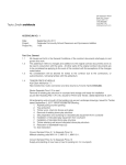
The Quick Reference Chart shown below may be used as a guide for quickly changing any particular parameter
stored within the system. Locate the parameter you wish to change in the column marked "ACTION" and follow
the simple instructions given under "Procedure". Remember that if the system is equipped with a Key Lock
feature, the switch must be turned to the UNLOCK position before making any changes.
ACTION
PROCEDURE
SELECT CURRENT
CHANNEL
PRESS
KEY
CHANGE SCALE
°F/°C READOUT
PRESS
KEY
ADJUST TIP
OFFSET CONSTANT
PRESS
KEYS
TIP
OFFSET
ADJUST SET TIP
TEMPERATURE
PRESS
KEYS
TIP
SET
CH
SELECT
˚F
˚C
[
[
or
or
]
]
TIP
OFFSET
TIP
SET
Table 3. Quick Reference Chart
48
47
Quick Reference
ACTION
PROCEDURE
PRESS & HOLD
ENTER
CALIBRATION
(CAL) MODE
TIP
SET
SET DEFAULT
TEMP SCALE
(°F/°C) **
PRESS
KEYS
TIP
SET
CHANGE LOWER
TEMP LIMIT **
PRESS
KEYS
TIP
SET
CHANGE UPPER
TEMP LIMIT **
PRESS
KEYS
TIP
SET
AUTO
PRESS
TEMP SETBACK ** KEYS
TIP
SET
AUTO POWER
DOWN **
POWER ON
RELEASE AFTER 3 SECONDS
+
TIP
SET
˚F
TIP
SET
TIP
OFFSET
TIP
SET
CH
SELECT
TIP
SET
TIP
SET
CH
SELECT
TIP
SET
TIP
SET
TIP
SET
TIP
OFFSET
˚C
[
or
]
[
or
[
+
]
or
TIP
SET
TIP
OFFSET
]
TIP
OFFSET
(Press
Twice)
TIP
SET
TIP
OFFSET
Automatically enabled or disabled with AUTO TEMP SETBACK feature.
** SYSTEM MUST BE IN CALIBRATION (CAL) MODE.
Table 3. Quick Reference Chart (Continued)
48
49
Quick Reference
ACTION
PROCEDURE
PRESS & HOLD
MANUAL SETBACK
ON ALL ACTIVE
CHANNELS
EXIT SETBACK ON
ALL ACTIVE
CHANNELS
+
PRESS & HOLD
+
RELEASE AFTER 1 SECOND
+
RELEASE AFTER 1 SECOND
+
Table 3. Quick Reference Chart (Continued)
50
49
Corrective Maintenance
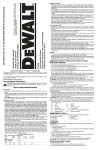
VisiFilter Element Replacement
Follow the procedure listed below to replace the VisiFilter element when it becomes clogged or discolored.
1. Disconnect the handpiece air hose by gently turning and pulling the coupled Fittings.
2. Disconnect the Visifilter and hose assembly from the Power Source by gently turning and pulling the
male Fitting inserted into the AUTO SNAP-VAC Port.
3. Disconnect VisiFilter from both attached 1 inch air hoses by gently turning and pulling the VisiFilter
while holding each of the hoses.
4. Separate the 2 plastic housing halves of the VisiFilter in the following manner.
3
a) Grasp the VisiFilter in the palm of the hand with the Male Nib (air hose connection) marked "FLOW
IN" facing you.
b) Pull against one of the Wing Tabs while pulling on the Male Nib with the free hand to open the
interconnection of the plastic housings at that Wing Tab.
c) Pull against the second Wing Tab while pulling on the Male Nib to open the remaining
interconnection and separate the plastic housings.
5. Remove the old or discolored Element and discard.
6. Insert the replacement VisiFilter Element into the housing marked "FLOW IN". Center the Element in
the housing well.
7. Squeeze the 2 plastic housing halves together using 4
plastic Bumps on the housing marked "FLOW OUT"
as pressure points. The 2 plastic housings will snap
together and lock the VisiFilter Element in position.
8. Reconnect the 1 inch air hoses (removed in step 3) to
the VisiFilter.
9. Attach VisiFilter and hose assembly to Power Source
by inserting male Fitting into the SNAP-VAC Port.
Figure 25. VisiFilter Element Replacement
50
51
Corrective Maintenance
Power Source
Most malfunctions are simple and easy to clear. Refer to Table 4 below to clear these malfunctions. If you
encounter any difficulty clearing the malfunction, contact PACE Technical Support directly at Tel. (toll free)
1-888-535-PACE (7223) or (301) 490-9860, FAX (301) 483-7030.
Symptom
Probable Cause
Solution
Digital Readout is blank.
No LEDs on. No motor.
Blown Fuse (F1)
Replace Fuse F1 located on rear of Power
Source in the AC Receptacle.
Defective handpiece.
Disconnect all handpieces. Check each
handpiece using the applicable handpiece
manual or Table 5 of this publication.
E-1 displayed on Digital
Readout.
No handpiece connected to Plug handpiece into CH 1, CH 2 OR CH 3.
power source.
Open sensor in handpiece.
Refer to handpiece Operation Manual for
Corrective Maintenance procedures.
E-2, E-3,E-4 or room
temperature displayed on
Digital Readout.
Defective handpiece.
Disconnect the handpiece connected to
the current channel (channel displayed on
Digital Readout). Check the handpiece
using the applicable handpiece manual or
Table 5 of this publication.
Insufficient AUTO
SNAP-VAC (vacuum) or air
pressure.
Filter(s) and/or handpiece(s)
require corrective
maintenance.
Refer to applicable handpiece manual(s) for
instructions on performing proper
"Corrective Maintenance" procedures.
Table 4. Corrective Maintenance, Power Source
52
51
Corrective Maintenance
Handpieces
The following "Heater Assembly Checkout Procedures" (Table 4) are applicable to all PACE handpieces except for
the TT-65 ThermoTweez & DTP-80 Dual ThermoPik handpieces. Refer to the respective handpiece manuals for
troubleshooting procedures pertinent to those handpieces. Use the Digital Readout Message Codes ("E-1", "E2", "E-3" or "E-4") listed on Table 4 (under "POWER SOURCE") as a guide to pinpointing any malfunction
associated with the handpiece.
Perform the "Heater Assembly Checkout Procedures" shown below with the handpiece (and heater) at room
temperature. If the handpiece is warm, resistance reading will be different from those shown in the table below.
Symptom
No heat
Checkout Procedure
Cause
Solution
Check resistance - Pin 2 to Pin Open Heater
Refer to "Heater Specifications" .
5
If resistance is high
Replace heater
bl
Check resistance - Pin 3 to Pin
6
If circuit reads open
Open Sensor
Replace Heater
A
bl
Handpiece
overheating
Check resistance - Pin 3 to Pin
If less than 105 ohms 6
Shorted Sensor
Replace Heater
A
bl
Fuse blows
when unit is
turned on.
Check resistance - Pin 2 to Pin
5
Refer to "Heater Specifications"
column. If resistance is low -
Solder short in
Handpiece.
Remove Short. Replace
Heater Assembly & Fuse
F1
Replace Heater Assembly
&
Fuse F1.
No Ground
on Tip.
Check resistance - Pin 4 to
NEW Tip. Resistance should
less than 2 ohms. If not b
Oxidation
b Heater
ild
in
Bore.
Shorted Heater
Heater
Specifications
SX-80 = 8 - 10 ohms
PS-90 = 8 - 10 ohms
TP-65 = 9 - 11 ohms
TJ-70 = 6 ohms
Clean heater bore
i h wire
proper
b h
Defective Heater Replace Heater
A
bl
Table 5. Heater Assembly Checkout Procedures
Figure 26. Handpiece Connector Plug
52
53
Spare Parts
Power Source
Listed below are the power source parts which may be ordered directly from PACE sales or your local authorized
PACE distributor. For handpiece replacement parts, refer to the associated Operation and Maintenance Manual.
To obtain power source parts other than those shown, contact your local PACE distributor or PACE directly at
Telephone (301) 490-9860, Fax (301) 483-7030.
PACE Model Number
Item
No.
1
Description
Fuse
(F1)
2.0 Amp, Time Lag
2.5 Amp, Time Lag
2
3
1.25 Amp, Time Lag
Power Cord (not shown in illustration)
MBT-250
1159-0247
-- - -- - - -
MBT-250E
-- - -- - - -- - -- - - -
1159-0257
1159-0217
1332-0094
1332-0093
Table 6. Power Source Replacement Parts
Figure 27. Power Source Parts
54
53
Spare Parts
Handpieces
Listed below are the handpieces available from PACE. The list is current at time of publication. Contact your
local authorized PACE distributor for additional information.
Item
#
1
2
3
4
5
6
7
8
9
10
11
12
Description
SensaTemp Handpieces
PS-90 Soldering Iron
SX-80 Sodr-X-Tractor
TJ-70 ThermoJet
TP-65 ThermoPik
DTP-80 Dual ThermoPik
TT-65 ThermoTweez
Tip and Tool Stands
PS-90 Tip and Tool Stand (Used with #1 above)
SX-80 Tip and Tool Stand (Used with #2 above)
Tip and Tool Stand (Used with #3,#4 above)
DTP Tip and Tool Stand (Used with #5 above)
TT Tip and Tool Stand (Ysed with #6 above)
Tip and Tool Stand Redi-Rak
Part Number
6010-0131-P1
6010-0106-P1
7023-0002-P1
7024-0001-P1
7029-0001-P1
7025-0001-P1
6019-0064
6019-0060
6019-0044
6019-0047
6019-0046
6021-0008
Table 7. Handpieces
54
55
Spare Parts
System Accessories
Listed below are the system accessories available from PACE. The list is current at time of publication. Contact
your local authorized PACE distributor for additional information.
Item #
Description
PACE Part Number
1
Tip Maintenance Station
6993-0138
2
Replacement Sponge for Tray (Qty. 7)
3
Fiber Cleaning Tool
4
Replacement Fiber Filler for #3 (Qty. 2)
5
Sponge Cleaning Tool
6
Replacement Sponge Filler for #5 (Qty. 5)
4021-0006-P5
7
Sponge, Tip and Tool Stand (Qty. 3)
4021-0008-P3
8
Tip Redi-Rak
6021-0007
9
Tip and Tool Stand Redi-Rak
6021-0008
10
Foot Pedal
6008-0115
11
Tip and Temperature Selection Chart
5050-0251
12
Tip and Temperature Selection Chart Holder
1257-0186-P1
13
Temperature Calibration/Set Key Lock
1273-0008-P1
14
Power Source Interlock Kit
6993-0141
15
Calibration Kit
6993-0133
16
Screwdriver, PACE
1100-0230
17
One Year Consumable Kit
6550-0019
18
Service Manual
5050-0352
19
Angle bracket Kit
6018-0097
4021-0007-P7
1100-0232
1127-0013-P2
1100-0233
Table 8. System Accessories
56
55
Warranty
LIM ITED WARRANTY
PACE warrants that this equipment will be free of defects in materials and workmanship for a
period of one (1) year from the date of receipt by the first user.
This warranty does not cover repair or replacement required as a result of misuse,
mishandling or improper storage. Failure to perform recommended routine maintenance,
alterations or repairs made other than in accordance with PACE’s directions, or removal or
alteration of identification plates in any way will void this warranty. This warranty is available
only to the first user, but the exclusions and limitations therein apply to all persons and entities.
This warranty does not apply to consumable items, such as tips, filter elements, hoses,
collection chambers etc., except that heaters are normally warranted for a period of six (6)
months from the date of receipt by the first user.
PACE MAKES NO OTHER WARRANTY, EXPRESSED OR IMPLIED, AND MAKES
NO WARRANTY OF MERCHANTABILITY OR FITNESS FOR A PARTICULAR
PURPOSE.
PACE will, at its option, repair or replace any defective equipment or parts at its facility or
other location approved by it at no charge to the user, or provide parts without charge for
installation by the user in the field at user’s expense and risk. User will be responsible for all
costs of shipping equipment to PACE or other warranty location for warranty service.
EXCEPT FOR THE REMEDY ABOVE DESCRIBED, UNLESS OTHERWISE
REQUIRED BY APPLICABLE LAW, PACE WILL HAVE NO OTHER OBLIGATION
WITH REGARD TO ANY BREACH OF WARRANTY OR OTHER CLAIM WITH
RESPECT TO THE EQUIPMENT, OR LIABILITY FOR ANY DIRECT, INDIRECT,
CONSEQUENTIAL, OR INCIDENTAL LOSS OR DAMAGE CAUSED BY OR
OCCURRING IN CONNECTION WITH ANY OF THE EQUIPMENT.
To obtain warranty service, contact the appropriate PACE company listed below
PACE Inc. 9893 Brewers Court, Laurel, Maryland 20723- 1990
Tel. (888) 535- 7223 (toll- free) Warranty Service FAX 301 483 7030
PACE Europe Ltd. Sherbourne House Sherbourne Drive Tilbrook Milton Keynes
United Kingdom MK7 8HX
Tel. (44) 01908 277 666 Warranty Service FAX (44) 01908 277 777
Do NOT return defective equipment or parts to PACE without obtaining prior authorization.
Any warranty or other claim with respect to the equipment must be made in writing and
delivered to PACE (or local authorized PACE Distributor outside the U.S.) within a
reasonable time of the expiration date of this warranty. Sufficient evidence of purchase and
date of receipt must also be included, otherwise user’s rights under this warranty shall be
deemed waived.
56
57