1
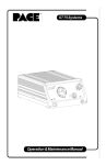
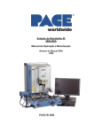
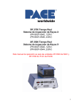
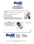
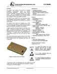
Operation and Maintenance Manual for the
SX-90 & SX-80 Sodr-X-Tractor Handpieces
5050-0492 Rev F
Part Number
6010-0106-P1
6010-0149-P1
6993-0213-P1
6993-0266-P1
Model
SX-80/90 (Black connector)
SX-90 (Blue Connector)
SX-80/90 (Black connector)
SX-90 (Blue Connector)
Features
Handpiece Only
Handpiece Only
Handpiece & Cubby
Handpiece & Cubby
PACE SX-90
(Shown)
PACE Sodr-X-Tractor Handpiece
TITLE
PAGE
Introduction ....................................................................................................................3
Tip & Tool Stand Setup ..................................................................................................4
Handpiece Setup............................................................................................................4
Vacuum Hose Connection .............................................................................................4
Tip Selection ..................................................................................................................5
Tip Installation ................................................................................................................5
Temperature Setting ......................................................................................................6
Burn In Procedure ..........................................................................................................6
Tip Preparation...............................................................................................................6
Through Hole Solder Extraction.....................................................................................7
Tip Cleaning ...................................................................................................................7
Special Applications .......................................................................................................8
Replacing the Disposable Solder Collection Trap .........................................................8
Heater Replacement ......................................................................................................9
Corrective Maintenance .................................................................................................9
Handpiece Replacement Parts .....................................................................................10
Service ..........................................................................................................................10
Contact Information ......................................................................................................11
©2008 PACE Inc., Southern Pines, NC. All Rights Reserved
www.paceworldwide.com
Page 2 of 11
PACE Sodr-X-Tractor Handpiece
These instructions detail the basic operational guidelines for using the SX-80 & SX-90 Sodr-X-Tractor handpieces.
The SX-80 has yellow coloration on it and the SX-90 has blue coloration on it. The SX-80 is only available in
SensaTemp technology while the SX-90 is available in SensaTemp and Intelliheat technologies.
Introduction
The Sodr-X-Tractor handpiece provides thermally enhanced through-hole desoldering on extra heavy multilayer
assemblies, at safer, lower temperatures, even during continuous use. This Sodr-X-Tractor handpiece features a large
easy to replace solder trap, slim-line, pencil grip design and finger actuated vacuum switch facilitates ease of use and
manipulation in tight places. The Sodr-X-Tractor is a member of the PACE SensaTemp family of advanced handpieces.
CAUTION
Always return heated handpieces to the appropriate Tip & Tool Stand when not
in use. Failure to do so may cause burns to the operator, equipment or work
surfaces and may be a potential ignition source if combustible materials are
nearby. Always use this handpiece in a well-ventilated area to avoid inhalation
of fumes created by solder flux.
NOTE
Always use your Sodr-X-Tractor with a clean VisiFilter element. Otherwise
deterioration in performance or damage to the unit may occur.
Select and enter your desired true operating temperature on your PACE power
source. To save tip life and reduce the possibility of damage, PACE
recommends using the lowest possible tip temperature that will provide rapid yet
controllable melt of the entire solder joint to be extracted. Begin with an
operating temperature in the range of 316°C (600°F) and adjust as necessary.
©2008 PACE Inc., Southern Pines, NC. All Rights Reserved
www.paceworldwide.com
Page 3 of 11
PACE Sodr-X-Tractor Handpiece
Handpiece Setup
Connect the handpiece connector plug into one of the Power Receptacles on
your PACE power source in the following manner.
1. Align guide on connector with slot on power receptacle.
2. Insert connector into power receptacle.
3. Turn the connector housing clockwise to lock in place.
Vacuum Hose Connection
To set up your Sodr-X-Tractor vacuum hose connection, perform the following steps:
1. Vacuum Hose To Handpiece Connection
a) Attach one end of a 137cm (54 inch) length of air hose to the metal tube in the back of the handpiece.
b) If you have a PACE system incorporating only one handpiece, attach the air hose to the SX-handpiece
power cable using the supplied Hose Clamps. Space them evenly along the length of the power cable
starting at a point 6 inches from the ends of the handpiece.
c) If you have a PACE system incorporating 2 or more air handpieces (e.g., SX-90/80,TP-100, TJ-70, TP-65),
you may wish to leave the air hose assembly unattached to allow a quick change to any air handpiece being
used.
NOTE
Insure that only one air handpiece is connected to either the Vacuum Port or
Controllable PRESSURE Port at one time. Attachment to both ports
simultaneously will cause a deterioration of performance.
2. Prepare a VisiFilter in the following manner:
a) Connect a 1-inch (2.5cm) length of clear PVC air hose to the
FLOW OUT side of the VisiFilter; push and turn the hose onto
the VisiFilter nipple to seat.
b) Insert the ribbed end of a male quick connect hose mount
fitting (P/N 1259-0087) into the free end of the 1 inch (2.5cm)
length of air hose connected to the FLOW OUT side of the
VisiFilter.
c) Connect the free end of the 137cm (54 inch) length of air
hose to the FLOW IN side of the VisiFilter.
d) Insert the end of the quick connect hose mount fitting (on
VisiFilter FLOW OUT side) into the power source Vacuum
Port.
3. When using air pressure, and/or utilizing multiple air handpieces,
PACE recommends the use of the following set up procedure which utilizes additional quick connect hose
mount fittings. An assortment of quick connect air fittings are supplied with each additional air handpiece.
©2008 PACE Inc., Southern Pines, NC. All Rights Reserved
www.paceworldwide.com
Page 4 of 11
PACE Sodr-X-Tractor Handpiece
a) Disconnect the 137cm (54 inch) length of air hose from the FLOW IN side of the VisiFilter assembly.
Insert the ribbed end of a male quick connect hose mount fitting (P/N 1259-0087) into the free end of
this air hose.
b) Connect the free end of a 1 inch (2.5cm) length of air hose with an installed female quick connect
hose mount fitting (P/N 1259-0086) to the FLOW IN side of the VisiFilter Assembly.
c) The 137cm (54 inch) length of air hose can now be easily moved between the VisiFilter Assembly
and the Controllable Pressure Port. The VisiFilter assembly remains connected to the Vacuum Port.
4. Additional fittings may also be added to the hose connection at the rear of each air handpiece to ease
changing of handpieces.
NOTE
When removing any air hose, turn and pull. Do not attempt to pull hose
directly off. Damage to or breakage of fitting or VisiFilter may occur. Use your
Sodr-X-Tractor with a clean VisiFilter element. Otherwise deterioration in
performance or damage to the unit may occur.
Tip Selection
PACE Endura Tips come in three basic types.
1.
Desoldering Tips - These tips are tinnable and provide enhanced thermal performance for thru-hole
desoldering on high mass boards.
2. Precision – These tip feature smaller ID sizes with larger mass for improved thermal recovery.
3. Flo-D-Sodr Tips - These tips provide rapid, continuous extraction of old or excess solder from SMT lands.
Size selection of tips is important. For thru-hole desoldering, select a tip with an I.D. just large enough to allow the lead
to freely pass inside. The tip O.D. should not exceed the diameter of the land to minimize risk of damage to the board
substrate.
Tip Installation
Before installing your desoldering tip, Identify your Sodr-X-Tractor heater assembly. Replacement SX-90
heater assemblies utilize part number 6010-0107-P1.
SX-70 tips are NOT compatible with SX-80 or SX-90 handpieces.
SX-80 (Endura) tips will operate in SX-70, SX-80 and SX-90 handpieces.
SX-90 tips are only compatible with SX-90 handpieces.
For optimal thermal transfer and performance, always use SX-90 tips with SX-90 handpieces and
heater assemblies.
©2008 PACE Inc., Southern Pines, NC. All Rights Reserved
www.paceworldwide.com
Page 5 of 11
PACE Sodr-X-Tractor Handpiece
For maximum productivity and proper fit, install tips into your Sodr-X-Tractor when the heater is hot.
CAUTION
During tip installation, hold the handpiece with the heater pointed at an up
ward angle to prevent injury.
1. Insert the tip fully into the heater bore using the supplied tip tool (P/N 1100-0206).
2. Gently tighten the Heater Set Screw.
3. Recheck the Heater Set Screw periodically to insure that it remains snug.
NOTE
Periodically, clean the heater bore with a properly sized 3/16" O.D. wire brush
(P/N 1127-0014-P5) to insure optimum heat transfer and proper tip grounding.
Temperature Setting
To save tip life and reduce the possibility of damage to the PCB, PACE recommends using the lowest possible tip
temperature that will provide rapid yet controllable melt of the entire solder joint. Begin with an operating
temperature of 316°C (600°F) and adjust as necessary. Tip temperatures in excess of 399°C (750°F) may cause
damage. For safest removal, some components on extra heavy assemblies may require preheating or auxiliary
heating.
Burn In Procedure
The following Burn In procedure must be performed to insure optimum performance and life
of this product:
1. Insure that system is located in a well-ventilated area on Initial power up.
2. Remove plastic cap from end of Heater Assembly (If present).
3. Connect Handpiece to PACE system Power Source.
4. Set Handpiece Tip temperature to 316°C (600°F). Burn Handpiece in for 10 minutes at this
temperature.
5.
Set Handpiece Tip Temperature to 427°C (800°F). Heater Assembly will again emit smoke. Burn
Handpiece in at this temperature until emission of smoke ceases. Approximately 15 minutes.
6.
Operate Handpiece in a normal manner.
Tip Preparation
Proper tip preparation will insure optimum results and increase tip life. Follow this procedure before each component
removal or land preparation operation and prior to storage of the handpiece in its Tip & Tool Stand.
1. Ensure that the installed tip is at set tip temperature.
2. Using a moistened sponge, remove all solder dross and flux residue from the tip.
3. Using a large gauge, flux cored wire solder, tin the end of these tips. Proper tinning enhances heat
transfer to lands and extends tip life.
4. During Flo desoldering or Thru-hole desoldering, on heavily fluxed or contaminated boards, debris
may collect inside the tip bore. If this occurs, clean the tip bore with the Sodr-X-Tractor Tip Cleaning
Kit (PACE part number 6993-0200).
©2008 PACE Inc., Southern Pines, NC. All Rights Reserved
www.paceworldwide.com
Page 6 of 11
PACE Sodr-X-Tractor Handpiece
5. The Sodr-X-Tractor handpiece is now ready for use. If not immediately using the handpiece, store
in its Tip & Tool Stand.
NOTE
Ensure that the tool stand sponge material is moist and free of debris. Add water
if necessary. Wiping the heated tip on a dry sponge will only contaminate the tip
and ultimately the board.
Through Hole Solder Extraction
1. Ensure that the handpiece vacuum hose is connected to a VisiFilter and the Vacuum Port on the power
source. Select an operating temperature that will cause complete solder melt in 2-5 seconds (somewhat
longer on heavy multilayer boards). A starting tip temperature of 316°C (600°F) is recommended for most
applications.
2. Position your index finger on the handpiece vacuum control switch.
3. Gently position the extractor tip over the lead contacting the solidified solder keeping tip perpendicular to
the pad and board. Do not apply pressure against the pad at any time during this operation.
Damage to the board may result.
4. Gently move the lead…..
a) In a circular motion for round leads
b) In a back and forth motion for flat leads
until the lead moves freely. Free lead movement indicates that complete solder melt has been obtained.
5. While continuing to move lead, actuate vacuum with the finger switch and keep on for at least 2 seconds to cool
joint and prevent re-sweating. The length of time from when heat is applied until the time vacuum is started (i.e.,
complete solder melt) should be 2-5 seconds under normal conditions. Heavy multilayer boards may require
somewhat longer heating times. In extreme cases, preheating or auxiliary heating is recommended to achieve
the safest results
.
NOTE
Early activation of the vacuum may result in incomplete removal of solder from
the joint being desoldered. Free movement of the lead is the work piece indicator
that proper solder melt has been achieved. In the event that all the solder has
not been removed from the hole, resolder the hole and try again after the board
has been allowed to cool.
6. Remove tip from pad and continue vacuum application for an additional 2 seconds to insure that all
residual solder is drawn into the solder collection chamber.
7. Re-tin tip using large gauge flux cored solder and return Sodr-X-Tractor to its Tool Stand.
8. After all leads are desoldered, the component is easily removed. If any solder should remain in the
plated thru-hole after extraction, resolder the connection and perform this procedure again.
Tip Cleaning
During heavy, continuous desoldering, on boards with flux residues or other contamination, the tip may
occasionally become clogged with such material. If this should occur, clean the tip with the Tip Cleaning Kit
(PACE part number 6993-0200) by inserting the wire tool into the tip end.
©2008 PACE Inc., Southern Pines, NC. All Rights Reserved
www.paceworldwide.com
Page 7 of 11
PACE Sodr-X-Tractor Handpiece
Special Applications
If you require assistance in the use of this handpiece or with a special application, contact PACE Technical
Support at:
Telephone: (301) 490-9860
Fax: (301) 490-0193
Replacing the Disposable Solder Collection Trap
As the Sodr-X-Tractor is used, solder and flux build-up will begin to impede the airflow and decrease system
performance. The SX-90 & SX-80 utilize a disposable chamber that makes maintenance a quick and simple
process. Regular replacement of the Sodr-Flux Trap will keep the Sodr-X-Tractor handpiece operating at peak
performance. To replace the Sodr-Flux Trap follow the procedures outlined below.
1. While holding the Sodr-X-Tractor with the tip facing
away from you and the handpiece in a downward
position, remove the door assembly from the
handpiece. This action is accomplished by pulling the
plunger lock approximately ¼” and turning it
approximately ten (10) degrees to the right or left. The
door assembly can now be removed by simply gripping
the door near the ear shaped protrusions and lifting
straight up.
2. Replace the disposable chamber by holding the door assembly in the palm of your hand with the filter
assembly facing up. With your free hand use a fresh solder chamber with the arrows facing away to push
the spent chamber out of the door assembly and into a waste receptacle. The fresh chamber is now in
position and ready for reassembly.
CAUTION
The handpiece will not function properly if the chamber is inserted incorrectly. The
directional arrows on the solder chamber must be pointed at the heater.
3. Complete the process by lowering the door into the handle assembly. Insure that the door is properly
situated with the ears seated in their respective detents. Now return the plunger assembly to its locked
position by simply twisting the plunger locks mechanism so that it returns to the channels in the handle
assembly.
4. Insure that the door assembly is securely in place by attempting to lift the door from the handle assembly. It
should now be held firmly in place.
5. Check all air hose fittings. Actuate the vacuum and insure that proper vacuum is present at the tip.
6. Return the handpiece to the cubby or resume work as required.
©2008 PACE Inc., Southern Pines, NC. All Rights Reserved
www.paceworldwide.com
Page 8 of 11
PACE Sodr-X-Tractor Handpiece
Heater Replacement
The Sodr-X-Tractor utilizes a modular heater design, which allows for a quick and easy change out of the heater
assembly.
1. Remove and set aside any installed tip from the handpiece.
2. Disconnect the handpiece from the receptacle of the power source.
3. Remove the two heater assembly screws. These screws can be accessed through the two holes found on the
face of the heater shroud.
4. After the two heater assembly screws have been removed and set aside, remove the heater assembly by
pulling the heater module straight out.
5. Reassemble the handpiece in the following order.
6. Align the modular heater plug with receptacle on the handle assembly and gently push into place.
7. Replace and tighten the two heater assembly screws. Insuring that the heater assembly is snugly in place
when through. Be careful not to over tighten the screws.
8. Connect the handpiece to the power source and return the handpiece to the cubby or resume work.
NOTE:
There are two heaters available for the SX80/90 handpieces. If your handpiece
came with a heater with a black plug-in connector you must order and use heater
part number 6010-0107-P1, if your handpiece came with a heater with a Blue plug-in
connector you must order and use heater part number 6010-0163-P1. A heater with
the blue connector will NOT fit in to a handpiece fitted with the black connector.
Corrective Maintenance
Your Sodr-X-Tractor requires no special maintenance other than being kept clean. The heater bore and the heater assembly
set screw, which secures the tip, must be kept free of oxidation and debris in order to maintain the proper tip-to-ground
resistance.
©2008 PACE Inc., Southern Pines, NC. All Rights Reserved
www.paceworldwide.com
Page 9 of 11
PACE Sodr-X-Tractor Handpiece
Handpiece Replacement Parts
Sodr-X-Tractor Exploded Diagram
SX-90 Replacement Part Numbers
Ref#
1
Description
Solder Flux Chamber
Handle Assembly (Black Connector)
2
Handle Assembly (Blue Connector)
3
Door Assembly
Heater Assembly (Black Connector)
4
Heater Assembly (Blue Connector)
5
Plunger Shaft
6
Plunger Lock
7
Front Seal
8
Rear Seal
9
"C" Clips
10
Spring "Long Slide"
11
Spring "Short Slide"
12
Door Lock
* NOT PICTURED
13*
Heater Set Screws Pack of 10
14*
Glass Flux Trap Kit
15*
Glass Chamber Only
Part Number
1309-0054-P10
6010-0115-P1
6010-0162-P1
1119-0141-P1
6010-0107-P1
6010-0163-P1
1261-0154-P1
1500-0063-P1
1213-0087-P1
1213-0086-P1
1348-0387-P3
1221-0136-P1
1221-0137-P1
1119-0142-P1
1348-0547-P10
6000-0212-P1
1265-0011-P1
Service
Please contact PACE or your local distributor for service and repair.
©2008 PACE Inc., Southern Pines, NC. All Rights Reserved
www.paceworldwide.com
Page 10 of 11
PACE Sodr-X-Tractor Handpiece
PACE Incorporated retains the right to make changes to specifications contained herein at
any time, without notice. Contact your local authorized PACE Distributor or PACE
Incorporated to obtain the latest specifications.
The following are trademarks and/or service marks of PACE, Incorporated, MD, USA:
INSTACAL™, FUMEFLO™, HEATWISE™, PACEWORLDWIDE™,
PERMAGROUND™, POWERPORT™, POWERMODULE™, TEMPWISE™, TIPBRITE™, AUTO-OFF™, TEKLINK™, and INTELLIHEAT™
The following are registered trademarks and/or service marks of PACE Incorporated, Annapolis
Junction Maryland U.S.A.
ARM-EVAC®, FLO-D-SODR®, MINIWAVE®, PACE®, SENSATEMP®, SNAPVAC®, SODRTEK®, SODR-X-TRACTOR®, THERMOFLO®, THERMOJET®,
THERMOTWEEZ®, VISIFILTER®, THERMO-DRIVE®, and TOOLNET®.
PACE products meet or exceed all applicable military and civilian EOS/ESD, temperature stability
and other specifications including MIL STD 2000, ANSI/JSTD 001, IPC7711, and IPC A-610.
Additional copies of this manual or other PACE literature may be obtained from:
www.paceworldwide.com
PACE USA
9030 Junction Drive
Annapolis Junction, MD 20701
USA
PACE Europe Limited
13 Tanners Drive Blakelands
Milton Keynes
MK145BU
United Kingdom
Tel:
(301) 490-9860
Tel:
(44) 01908-277666
Fax:
(301) 498-3252
Fax:
(44) 01908-277777
©2008 PACE Inc., Southern Pines, NC. All Rights Reserved
www.paceworldwide.com
Page 11 of 11