1
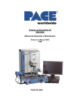
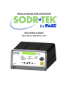
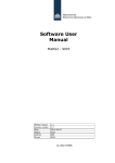
Operation and Maintenance Manual for the
SODRTEK®
ST 350 Digital Convective
Soldering/Desoldering System
P/N 5050-0543 REV 5-07
Shown with optional ST 450 Pre-Heating System
TITLE
PAGE
General Information .......................................................................................................4
Introduction...........................................................................................................4
Microprocessor Control ........................................................................................4
ST 350 Precision Reflow Head ............................................................................4
Specifications .......................................................................................................4
Parts Identification................................................................................................6
Safety .............................................................................................................................9
Safety Guidelines .................................................................................................9
Usage Warnings/Cautions....................................................................................9
Servicing Precautions..........................................................................................10
System Set-Up ..............................................................................................................10
Unpacking and Assembly Instructions ................................................................10
Unpacking..................................................................................................10
Assembly ...................................................................................................10
Setup ...................................................................................................................11
Vacuum Pick .......................................................................................................12
Quickfit Nozzle Adapter.......................................................................................12
Nozzle Selection..................................................................................................13
Nozzle Changeout.........................................................................................................13
Removal ..............................................................................................................13
Installation ...........................................................................................................13
Definitions......................................................................................................................14
System Power Up .........................................................................................................14
Set Up Mode .................................................................................................................15
Automatic Calibration ....................................................................................................16
Operation.......................................................................................................................17
PCB Mounting .....................................................................................................17
Password.............................................................................................................19
Front Panel Selections ........................................................................................19
Reflow Head Positioning .....................................................................................20
Vacuum Pick Positioning.....................................................................................22
Pik-Vak Operation ...............................................................................................22
Component Removal; Manual Mode...................................................................23
Component Installation; Manual Mode................................................................25
Timed Removal ...................................................................................................27
Timed Install ........................................................................................................28
PC Control.....................................................................................................................30
Memory .........................................................................................................................30
Save ....................................................................................................................30
Recall...................................................................................................................31
Process Development ...................................................................................................31
Profile Development ............................................................................................31
General Process Guidelines .........................................................................................35
Board Preparation ...............................................................................................35
Component Positioning .......................................................................................35
Preheating ...........................................................................................................35
Corrective Maintenance ................................................................................................36
Display Error Messages ......................................................................................36
Power Source ......................................................................................................36
Vacuum Pick Replacement .................................................................................37
Removal.....................................................................................................37
Installation..................................................................................................40
Packing List...................................................................................................................42
©2004 PACE Inc., Annapolis Junction, Maryland
All Rights Reserved
Page 2 of 45
Spare Parts ...................................................................................................................43
Service ..........................................................................................................................43
“SODRTEK by PACE” LIMITED WARRANTY STATEMENT.......................................44
Contact Us.....................................................................................................................45
©2004 PACE Inc., Annapolis Junction, Maryland
All Rights Reserved
Page 3 of 45
General Information
Introduction
Thank you for purchasing the PACE SODRTEK® model ST 350 Analog Convective
Soldering/Desoldering System. This manual will provide you with the information necessary to
properly set up, operate, and maintain the ST 350. Please read this manual thoroughly before using
the unit. The ST 350 unit is a complete system designed for hot air removal and installation of SMD
components, including Ball Grid Arrays (BGAs). The following key features allow process controlled
placement and reflow of BGAs and SMD components. The ST 350 will store up to 20 profiles on its
own. A PC can be used to store up to additional profiles and to collect the thermocouple data.
Microprocessor Control
The microprocessor system offers precision control of temperature (closed-loop control), cycle time
(adjustable by one second increments), and blower speed provides consistent, repeatable results in
successive reflow operations. Utilizing the Quiet Flo (low noise) turbine blower, pressure/flow rate is
easily controlled and maintained at optimum levels for the particular task. A multi-level password
lock-out prevents unauthorized changes and an audible countdown timer indicates end of cycle.
ST 350 Precision Reflow Head
The user-friendly ST 350 Reflow Head incorporates a powerful heater and has cycle and vacuum
switches on a versatile cable remote. A built-in, self-adjusting vacuum pick has a push-pull action,
allowing components to be lifted automatically after solder reflow.
The ST 350 unit is available in either the 115 VAC or 230 VAC version. The 115 VAC version system
bears the FCC Conformity Marking which assures the user that it conforms to all the requirements of
FCC Emission Control Standard, Title 47, Subpart B, Class A. This standard is designed to provide
reasonable protection against harmful interference when the equipment is operated in a commercial
environment. The 230 VAC version system bears the CE Conformity Marking which assures the user
that it conforms to all the requirements of (EU) directive EMC 89/336/EEC & 73/23/EEC.
Specifications
ST 350 - Operates on 97-127 VAC, 60 Hz (115 VAC version)
575 Watts maximum at 120 VAC, 60 Hz
ST 350E - Operates on 197-264 VAC, 50 Hz (230 VAC version)
575 Watts maximum at 230 VAC, 50 Hz
Air Temperature Range - 149°C - 482°C (300°F - 900°F)
Timing Control - 10 to 999 seconds with 1 second resolution. (does not include preheat time)
Blower Air Flow Rate (measured at heater) - 20 SLPM (0.7 SCFM) minimum at highest speed (9).
- 5 SLPM (0.18 SCFM) minimum at lowest speed (1).
Vacuum (at Pik-Vac Port) - 7.6 cm Hg. (3 in. Hg.) minimum.
NOTE: The ST 350 is designed for cyclical usage. Attempts to use in continuous operations may
void Blower Assembly warranty.
Component Capacity - (maximum size) - 5.1 cm x 5.1 cm (2” x 2”)
©2004 PACE Inc., Annapolis Junction, Maryland
All Rights Reserved
Page 4 of 45
Physical Parameters
Size – 57.8 cm H x 93 cm W x 66.5 cm D (22.75” H x 36.62” W x 26.17” D)
Unit Weight – 26.31 Kg. (58 lbs.)
©2004 PACE Inc., Annapolis Junction, Maryland
All Rights Reserved
Page 5 of 45
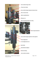
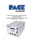
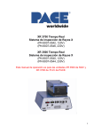
Parts Identification
LCD
Display
Power Switch
Illuminated LoFlo
Pump Switch
Menu Key
Sroll Keys
Select Key
LoFlo Vacuum Port
K-type
Thermocouple
Receptacle
RS 232 PC Input
Fuse
Fuse
Remote Controller
Receptacle
AC Power Receptacle
Earth Ground Receptacle
©2004 PACE Inc., Annapolis Junction, Maryland
All Rights Reserved
Pre-Heater Receptacle
(ST 450)
Page 6 of 45
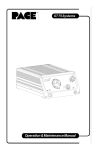
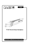
Vacuum Pick Plunger Knob
Theta Control Knob
Vacuum Pick Height Adjustment Control Knob
Z-Axis Control Knob
Reflow Head Rail Knob
Z-Stage Lock
Reflow Head Repeatable Down Stop
X-Axis Adjustment Knob
Vacuum Pick Height Adjustment Locking Knob
Y-Axis Adjustment
Y-Axis Adjustment Lock
Heat Shield
Quickfit Nozzle Adapter
Nozzle Assembly
Vacuum Pick Assembly
©2004 PACE Inc., Annapolis Junction, Maryland
All Rights Reserved
Page 7 of 45
Tension Slide
Rail Adjustment Knob
PCB Support
Board Holder Rails
“X” Axis Fine Adjustment Knob
“Y” Axis Fine Adjustment Knob
©2004 PACE Inc., Annapolis Junction, Maryland
All Rights Reserved
Page 8 of 45
Safety
Safety Guidelines
The following are safety precautions that personnel must understand and follow when using or
servicing this product.
“NOTE”
Used to indicate a statement of company recommendation or policy. The message may relate
directly or indirectly to the safety of personnel or protection of property. NOTE is not associated
directly with a hazard or hazardous situation and is not used in place of "CAUTION", "WARNING"
or "DANGER".
“CAUTION”
Used to indicate a hazardous situation, which may result in minor or moderate injury. May also be
used to alert personnel to conditions, procedures and practices which, if not observed, could
result in damage to or destruction of the product or other equipment.
“WARNING”
Used to define additional information that if not closely followed might result in serious damage to
equipment and represent a potential for serious personnel injury.
“DANGER”
Defines additional information that if not closely followed might result in severe personnel injury or
death. Danger is not used for property damage unless personal injury risk is present.
Usage Warnings/Cautions
WARNINGS
1. A fire hazard may arise if the ST 350 is used improperly.
2. Do not use the ST 350 in the presence of an explosive atmosphere.
3. Be careful when using the ST 350 in places where there are combustible materials. Heat
may be conducted to combustible materials which are out of sight.
4. Do not apply heat from the ST 350 to one place for a long time.
5. Do not leave the ST 350 unattended while powered on.
CAUTIONS
1. The ST 350 heater assembly housing and any installed nozzle are hot when the system
is being cycled and for a period of time thereafter. DO NOT touch either the heater
assembly housing, nozzle or direct heated air stream. Severe burns may result!
2. Utilize all standard electrical safety precautions when using this or any other electrical
equipment.
©2004 PACE Inc., Annapolis Junction, Maryland
All Rights Reserved
Page 9 of 45
3. Always use this system in a well-ventilated area. A fume extraction system such as those
available from PACE are highly recommended to protect personnel from solder flux
fumes.
4. Exercise proper precautions when using chemicals (e.g., solder paste). Refer to the
Material Safety Data Sheet (MSDS) supplied with each chemical and adhere to all safety
precautions recommended by the manufacturer.
Servicing Precautions
DANGERS
POTENTIAL SHOCK HAZARD - Repair procedures performed on this product should be
performed by qualified service personnel only. Line voltage parts will be exposed when
equipment is disassembled. Service personnel must avoid contact with these parts when
troubleshooting.
Precautions
The following are general safety precautions which personnel must understand and follow when
using or servicing this product. These precautions may or may not be included elsewhere in this
manual.
Safety
Electrical Requirements
The ST 350 unit draws approximately 575 Watts, which is listed on the nameplate on the
power source rear panel. A separate, dedicated AC supply line circuit may be required to
adequately power the unit/system. If your power outlet cannot provide suitable power,
arrange for a qualified, licensed electrician to install one for you.
System Set-Up
Unpacking and Assembly Instructions
Unpacking
1. Remove the ST 350 from its shipping container(s). Store the shipping container(s) in a
convenient location. Reuse of these containers will prevent damage if you ship or store the
system.
CAUTION: When removing the ST 350 from the shipping container, lift from under the frame.
Do not lift by the heater head assembly or the X-Y Fine Adjustment Plates.
2. After positioning the unit on a worktable, remove the two red slotted head shipping screw
before attempting to move the heater head along the Y-axis. Be sure to retain the screws for
further shipments.
3. Cut and remove the 2 ty-wraps used to immobilize the X-Y Fine Adjust Plates before
attempting to rotate the micrometer heads.
Assembly
1. Locate the four threaded holes on the X-Y fine adjustment plates.
©2004 PACE Inc., Annapolis Junction, Maryland
All Rights Reserved
Page 10 of 45
2. Install the rail assembly using the four flat head screws and the 5/64” hex key.
CAUTION: The aluminum plates will be damaged if over tightened, so be sure to only snug the
rail assembly down.
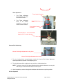
3. The completed installation should look like the picture below. The longer part of the rail
assembly should extend out from the side of the system as shown by the arrows.
Set Up
Set up the ST 350 system using the following steps and associated drawings.
1. Set the ST 350 unit on a convenient workbench.
2. Place the POWER Switch in the "OFF" or "0" position.
3. Inspect all system components to check for shipping damage and to
ensure that all purchased components (standard and options) are
present. Use the drawings provided in the following pages as a guide for checking the parts
that come with the unit.
©2004 PACE Inc., Annapolis Junction, Maryland
All Rights Reserved
Page 11 of 45
Vacuum Pick
Set-Up
1. Locate the Pik-Vac (P/N 7027-0001-P1) and the Vacuum Cup
Kit (P/N 6993-0154) supplied with the system.
2. Attach the ridged end of a male quick connect hose mount
Fitting to each end of the Air Hose.
3. Attach one male quick connect hose Fitting (with attached Air
Hose) to the rear of the Pik-Vac Handpiece.
4. Insert the other male quick connect hose
Fitting (with attached Air Hose) into the LoFlo Vacuum Port.
5. Attach the Metal Vacuum Tip, with the appropriate vacuum cup,
to the end of the Pik-Vac Handpiece.
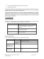
QuickFit Nozzle Adapter
The ST 350 QuickFit Adapter allows you to easily change out any PACE
ST 350 Nozzle. Attach the adapter to the heater using the following
instructions.
1.
Insert the QuickFit Adapter into the end of the handpiece heater as
shown.
2. Position the QuickFit Adapter so the Line on the heater is aligned with
one of the 3 lines (1 long & 2 short lines) on the Locking Collar.
Tighten Collar Locking Screw to secure adapter in position.
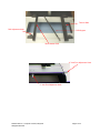
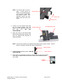
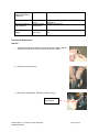
Optional ST 600 Digital Paste Dispensing System
The ST 600 can be mounted into the ST 350. From the factory, the ST 350 has a panel cover over
the ST 600 cradle. Simply remove the panel and insert the ST 600 into the cradle.
ST 600 Cradle location
Panel Cover Removal
©2004 PACE Inc., Annapolis Junction, Maryland
All Rights Reserved
Page 12 of 45
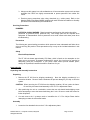
Nozzle Selection
Selection of the proper Nozzle is essential for achieving a quality component removal or installation. Each
ST 350 Nozzle is designed to properly direct the heated air. Custom nozzles are available upon request.
ST 350 Nozzles are available in 4 basic configurations.
Vented Air Nozzles (V-A-N)
Are used for removal/replacement of BGA components.
Box Nozzles
Used for removal/replacement of surface mount components having solder
connections on 4 sides of the component (e.g., QFPs & PLCCs).
Pattern Nozzles
Used for removal/replacement of surface mount components having solder
connections on 2 sides of the component (e.g., SOICs).
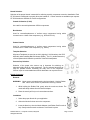
Template Selection
Alignment Templates are used as an aid in aligning V-A-N Nozzles to the PCB
Assembly when installing Ball Grid Arrays (BGAs). The I.D. (Inside Dimension)
of the template should match the perimeter of the BGA land pattern.
Vacuum Cup Selection
Selection of the proper size vacuum cup is important for achieving an
adequate holding force for each component. The cup selected should be as
large as possible without exceeding the body size of the component.
Vacuum cups are consumable items which deteriorate over a period of time.
Nozzle Changeout
Removal
WARNING:
Never remove a heated nozzle using bare hands. Use the Rubber
Pad. Never use a wrench or pliers when removing a nozzle.
1. While holding the Rubber Pad, gently twist the nozzle as shown. The
nozzle will easily release from the Nozzle Adapter.
2. Place the nozzle (still hot) on a heat resistant surface.
Installation
1. Select the proper Nozzle for your application
2. Orient the Nozzle for best use on the component.
3. Insert the Nozzle up into the Nozzle Adapter (use Rubber Pad if nozzle is
hot). Gently twist the nozzle as shown to lock nozzle in place.
©2004 PACE Inc., Annapolis Junction, Maryland
All Rights Reserved
Page 13 of 45
Definitions
Please read and become familiar with the definitions of each of the following terms which are used
repeatedly in the following Operation, Set-Up Mode and Program Mode procedures.
Manual Mode: Mode of operation in which the operator sets only Operating Temperature and Blower
Speed parameters. The operator then manually performs a rework operation.
Operating Temperature: The true air stream temperature as it exits the handpiece heater assembly.
This temperature is displayed on the Digital Readout during any given rework cycle where air is flowing
through the handpiece.
Password: The password feature, when activated will prevent unauthorized alteration of stored system
parameters. If a password has been installed, the Digital Readout will display an instruction to enter the
password (a 4 key numerical sequence stored in Set-Up Mode) when a setting change is attempted.
Preheat: A preliminary process in which the work is heated at a predetermined rate from ambient to a
desired elevated temperature in order to reduce the risk of thermal shock and to reduce cycle time during
the Reflow (primary heating) process.
Profile: An established procedure for rework which includes all parameters (e.g., operating temperature,
cycle time, preheat) required for optimum rework of a particular component/PCB combination. Any
established Profile can then be utilized by entering it into system memory; the Profile can then be easily
recalled and used in the system Program Mode.
Program Mode: Mode of operation in which a profile can be stored, altered (edited), or recalled and
used to automatically sequence through the established procedure once the cycle is initiated.
Set Temperature: The operator selected air stream temperature for the particular rework cycle.
Set-Up Mode: Mode of operation in which the operator can quickly and easily enter, change or delete
system parameters (e.g., password, °C/°F display, profile deletion).
Timed Mode: Mode of operation in which the operator enters the Operating Temperature, Cycle Time,
vacuum operation and Blower Speed parameters. When the reflow cycle is initiated, the system will
operate as per those parameters and turn off at the end of the cycle time. The operator manually
performs any other required procedures (e.g., vacuum operation, preheat) of the rework operation.
Vacuum Release Time: Time delay from the start of a Reflow cycle (in Program Mode, Install only) until
vacuum terminates to release component.
V-A-N Nozzle: Vented Air Nozzle.
System Power Up
1. Insert the female end of the power cord into the AC Power Receptacle on the rear panel of
the power source.
2. Plug the prong end (male end) of the power cord into an appropriate 3 wire grounded AC
supply receptacle.
CAUTION: To insure operator and ESD/EOS safety, the AC power supply receptacle must be
checked for proper grounding before initial operation.
©2004 PACE Inc., Annapolis Junction, Maryland
All Rights Reserved
Page 14 of 45
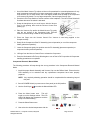
3. Connect the ST 350 Remote to the system.
Remote
Connection
ST 350 Rear
Panel
Set Up Mode
The set up mode provides the selection of the following items:
1.
2.
3.
4.
Password Entry
Temperature scale selection (°C or °F)
Auto Vac
Deletion of profiles
1. Turn Power Switch Off.
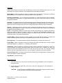
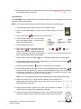
2. Turn the ST 350 On while holding the Menu Button. Release the Menu Button when the LCD
displays the Development Date (e.g., “Dev 4/06/04”). The LCD will now display “Password
Needed?” if there is no password currently stored in the system. If a password is stored, the LCD
will display “Enter Password” and “Password = 0000.” Notice that the question mark is no longer
present.
3. If there is no Password stored and you would like to create one, press the Scroll Up Button ( )
for yes and go to step 5. If there is no Password stored and you do not want to create one, press
the Scroll Down Button ( ) or the Select Button for no and go to step 6.
4. If there is a Password stored, use the Scroll Keys (
) to select the stored password.
NOTE: If an incorrect password is entered, the system will display “Wrong Password” and exit
out of the Set Up Mode.
5. Enter the Password using the Scroll Keys (
).
NOTE: Please copy the chosen password and keep in a safe place.
6. Press the Select Button after the password is selected. The LCD will now display the desired
temperature scale (e.g., “Display is °F?”).
7. Use the Scroll Down Button ( ) to select the desired temperature scale.
8. Press the Select Button or the Scroll Up Button (
of the Auto Vac, (e.g., “Auto Vac = On”).
) to save. The LCD will now display the status
9. Use the Scroll Down Button ( ) to select the desired Auto Vac state.
10. Press the Select Button or the Scroll Up Button ( ) to save. The LCD will now display “Delete
Profiles?”. If you want to delete a profile, press the Scroll Up Button ( ). If you do not want to
delete a profile, press the Scroll Down Button ( ). The LCD will now display “Exit Setup?”
©2004 PACE Inc., Annapolis Junction, Maryland
All Rights Reserved
Page 15 of 45
11. Use the Scroll Up Button ( ) for yes and the Scroll Down Button ( ) for no. If no is selected,
the program will cycle to the beginning and the LCD will display “Password Needed?”.
12. If the Scroll Up Button (
) is selected, the LCD will flash “Delete Profile and Number -- ?”
13. Use the Scroll Keys (
) to select the desired profile number (1-40) and then press the Select
Key. The Screen will now ask you to confirm the deletion, (e.g., “24 are you sure?”).
14. Use the Scroll Up Button (
) for yes and the Scroll Down Button ( ) for no.
15. If no is selected, the system will prompt the user to exit the set up mode. Use the Scroll Up
Button ( ) for yes and the Scroll Down Button ( ) for no. If no is selected, the program will
cycle to the beginning and the LCD will display “Password Needed?”.
Automatic Calibration
The ST 350 System provides precision control of temperature thanks to the closed-loop controlled circuit
design. The temperature sensor is located in the heater but utilizing the PACE Thermocouple Nozzle can
yield more accurate results due to moving the temperature sensor closer to the component. The
Automatic Calibration Procedure allows the system to calibrate for various style components as well as to
adjust for any minor offsets in temperature due to heater differences and blower speeds. Doing this will
ensure the most accurate temperature readings.
NOTE: For best results, hold a PCB up to the Thermocouple Nozzle at the same distance as the nozzle
would be from the PCB during the removal or installation process. During the calibration it is
important to avoid holding the PCB in one position too long; this will avoid board damage during
the Automatic Calibration Procedure.
Entering the Automatic Calibration Mode
1. Turn the Power Switch Off.
2. Install the Thermocouple Nozzle.
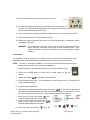
3. Press and hold the Scroll Up Button ( ) and Select Button while turning the Power Switch On.
Release these buttons when software development date appears, e.g., “Dev Date 8-20-04.”
4. The LCD will flash, displaying “Ent Auto Temp” and “A Temp = ___ °.”
NOTE: The “A - Temp = ___ ° “ will display the current
temperature that is set in the Manual Mode (e.g.,
“A -Temp = 700 °F”).
5. Use the Scroll Keys (
) to select the desired temperature and press the Select Button to
accept the entry. If the Scroll Keys are not pressed for a duration of 5 seconds, the LCD will
return to the flashing of the “Ent Auto Temp” and “A -Temp = ___ °.”
©2004 PACE Inc., Annapolis Junction, Maryland
All Rights Reserved
Page 16 of 45
6. The LCD will flash, displaying “Auto Blower = 7” and “Ent Auto Blower.”
NOTE: The “Auto Blower = ___ “ will display the current temperature that is set in the Manual
Mode (e.g., “Auto Blower = 7”).
7. Use the Scroll Keys (
) to select the desired blower speed and press the Select Button to
accept the entry. If the Scroll Keys are not pressed for a duration of 5 seconds, the LCD will
return to the flashing of the “Auto Blower = 7” and “Ent Auto Blower.”
8. Press the Cycle Button to start the Calibration Process.
NOTE: Anytime during this operation the Vacuum Button can be pressed to
escape the process.
9. Once the process is completed, the LCD will display “Save Offset?” At this time, the offset may be
saved by pressing the (
) Up Key or the Offset Calibration Mode may be exited by pressing the
down key or the Vacuum Button on the handpiece. Either selection will exit the Offset Calibration
Mode and place the system into the previously used menu for regular operation.
NOTE: If during the procedure the LCD displays “ Auto Cal Error,” repeat the Auto Calibration
Procedure again.
Operation
The PACE ST 350 unit is easy to operate and can be quickly set up for operation. The following steps
provide basic guidelines for rework using the PACE ST 350.
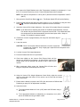
PCB Mounting
NOTE: The various boards can be installed using either the Fingers for odd shaped boards or by
placing the board into the upper or lower channels in the Board Holder Rails.
Board Installation (For Standard Boards)
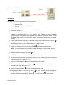
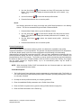
1. Loosen the Rail Adjustment Knobs.
2
Tension
Removed
Verify that the tension is “off” on the Tension Slide.
Note that when the tension is removed, the Board Holder Rail is retracted.
NOTE: The tension slide is used to apply a small amount of tension on the
PCB assembly once the Board Holder Rails are secured in place.
This additional tension will help further retain the PCB in the fixture.
©2004 PACE Inc., Annapolis Junction, Maryland
All Rights Reserved
Page 17 of 45
NOTE: The tension slide is used to
apply a small amount of
tension on the PCB assembly
once the Board Holder Rails
are secured in place. This
additional tension will help
further retain the PCB in the
fixture.
Tension Slide
Tension “Off”
Tension “On”
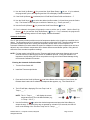
3. Position one of the Board Holder Rails
into the desired position and then
tighten the Rail Adjustment Knobs on
that
side
only.
(DO
NOT
OVERTIGHTEN)
Rail Adjustment Knob
Board Holder Rail
4. Place the board on the Board Holder
Rail that has already been secured, then
slide the adjacent Rail Assembly to
support the board.
NOTE: There are two channels in the Board Holder Rail that will accept the board. This will
allow the mounting of boards with various configurations.
Upper Channel
5. Tighten the Rail Adjustment Knobs. (DO NOT
OVERTIGHTEN)
Lower Channel
6. Place tension on the board by placing the Tension Slide into the proper position.
At this point the Board Holder rail will extend and provide additional pressure
on the PCB.
Tension
Applied
©2004 PACE Inc., Annapolis Junction, Maryland
All Rights Reserved
Page 18 of 45
Board Installation (For Odd Shape Boards)
1. Loosen the Rail Adjustment Knobs.
Board Holder Rail
Rail Adjustment Knob
2. Verify that the tension is “Off” on the
Tension Slide.
Finger
3. Position one of the Board Holder Rails
into the desired position and then
tighten the Rail Adjustment Knobs on
that
side
only.
(DO
NOT
OVERTIGHTEN)
4. Slide the adjacent Rail Assembly at an
approximate location where the board
will rest.
Finger Pin
Thumbscrew
5. Loosen the Thumbscrew on the Finger.
6. Adjust the Finger into a position so that the board rests into the grove on the Finger Pin.
7. Tighten the Thumbscrew on the Finger.
8. Place tension on the board by placing the Tension Slide into the proper position.
Password
The Password feature of the ST 350 system, when activated, will prevent unauthorized alteration of
stored system temperature parameters and custom settings (refer to the “Set Up Mode Section”). If a
Password has been installed, the LCD Display will display an instruction to enter the Password (a 4
digit number) when a setting change is attempted. Entry of the correct Password at this point will
allow the operator to proceed with the desired changes.
Front Panel Selections
The front panel on the ST 350 contains a four button interface which allows easy operation of the
system, including creating and modifying profiles. There are four different selections within the
Mode column. They are Manual, Timed Install, Timed Removed, and PC Control. The
following pages will provide step-by-step procedures for the various modes.
©2004 PACE Inc., Annapolis Junction, Maryland
All Rights Reserved
Page 19 of 45
Reflow Head Positioning
The following procedure will step through the operational adjustments for the ST 350 Reflow Head
Assembly.
Sliding the Reflow Head Assembly into position
1. Grasp the Reflow Head Knob and pull into position.
2. When complete, gently push the Reflow Head into the
“parked” position.
Z Axis Control
Knob
Raising/Lowering the Reflow Head Assembly
1. To move the reflow head in the Z axis,
Z – Stage Lock
simply turn the Z axis Control Knob as
required. The Z – Stage Lock is used to
apply tension to the vertical slide
assembly. If it is too tight the reflow
head will be difficult to move and if it is
too lose it will drift down. The lock is
adjusted at the factory and should not
be adjusted unless there is a problem with the reflow head drifting or if the reflow head is
too difficult to move with the Z axis control knob. Do not over tighten Z-Stage Lock. A
properly adjusted Z-Stage lock will allow the Z Axis Control Knob to move to any position
without slipping.
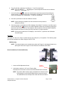
Adjusting the Reflow Head Repeatable Down Stop
1. Raise the Reflow Head Assembly
2. Adjust the Thumbscrew Stop to the desired position
3. Secure the Thumbscrew Jam Nut against the Thumbscrew Stop
Thumbscrew Stop
Reflow Head Planarity
Thumbscrew Jam Nut
X-Axis Adjustment
©2004 PACE Inc., Annapolis Junction, Maryland
All Rights Reserved
Page 20 of 45
X-Axis Thumbscrew
1. Turn the X-Axis Thumbscrew to position the Reflow Head
to the desired position.
2. Verify the position by lowering the Reflow Head Assembly to the PCB and inspect the
planarity between the Nozzle and the PCB.
X-Axis Adjustment - Moves the Reflow
Head up to 2° in either direction.
Y-Axis Adjustment
1. Rotate the Y-Axis Adjustment Lock until it points downward towards the system base.
2. Turn the Y-Axis Thumbscrew to position the Reflow Head to the desired position.
3. Verify the position by lowering the Reflow Head Assembly to the PCB and inspect the
planarity between the Nozzle and the PCB.
4. Rotate the Y-Axis Adjustment Lock until it points upward.
Y-Axis Thumbscrew
Y-Axis Adjustment Lock
Y-Axis Adjustment - Moves the Reflow
Head up to 2° in either direction.
©2004 PACE Inc., Annapolis Junction, Maryland
All Rights Reserved
Page 21 of 45
Theta Adjustment
Turns Nozzle Clockwise
1. Turn Theta Adjustment
Knob clockwise to rotate
the nozzle clockwise.
2. Turn Theta Adjustment
Knob to the counter
clockwise to rotate the
nozzle counter clockwise.
Theta Adjustment
Knob
Turns Nozzle Counter
Clockwise
Theta Adjustment - Moves the Reflow
Head up to 10° in either direction.
Vacuum Pick Positioning
Vacuum Pick Height Adjustment Locking Knob
Vacuum Pick Height Adjustment Knob
1. Turn the Locking Knob counterclockwise unlocks the Vacuum Pick Height Adjustment
Assembly and allows operation of the Adjusting Knob.
2. Turn the Adjustment Knob to adjust the vacuum pick to the desired position.
NOTE: Turning the Vacuum Pick Height Adjustment Knob clockwise lowers the vacuum pick
and turning it counterclockwise raises the vacuum pick.
3. Once into position, turn the Locking Knob clockwise to lock the vacuum pick into position.
Pik-Vac Operation
©2004 PACE Inc., Annapolis Junction, Maryland
All Rights Reserved
Page 22 of 45
1. Use of the Metal Vacuum Tip without a Vacuum Cup attached for removal/replacement of very
small component works well but for larger components, install one of the supplied Vacuum
Cups onto the tip. For best results, use a size slightly smaller than the body of the component
to be removed or placed. For very large components, use the largest Vacuum Cup.
2. Press the LoFlo Pump Switch to activate vacuum at the handpiece. The LoFlo Pump Switch will
illuminate whenever the switch is activated.
3. Grasp the handpiece as you would a pen, with the Vacuum
Cup (or tip) pointing down and the Vacuum Control Port
pointing up.
4. Place the Vacuum Cup and/or the Metal Vacuum Tip gently
onto the top surface of the Component body. Exercise
caution to avoid bending of leads on fine pitch devices.
5. Place one finger over the Vacuum Control Port. Vacuum is now being applied to the
Component body.
6. Gently lift the Component off the PC Assembly (removal operation) or out of the component
holder (placement operation).
7. Lower the Component gently into position onto the PC Assembly (placement operation) or
component holder (removal operation).
8. Lift finger from the Vacuum Control Port to release the Component.
9. Press the Illuminated LoFlo Pump Switch again to turn off the LoFlo Pump when all Component
handling operations are completed.
Component Removal; Manual Mode
The following procedure will step through the set up procedure in the Component Removal Manual
Mode.
1. Install the proper Nozzle Assembly and Vacuum Cup onto the Reflow Head. Ensure that the
PCB assembly to be reworked and any replacement component have been properly
prepared.
NOTE: Any required preheating operation should be completed before advancing beyond
this point.
2. Set unit POWER Switch (on power source front panel) to the ON position.
3. Use the Scroll Keys (
) to select the Manual Mode LED.
4. Press the Menu button once. This will
toggle you to the Settings column. The LCD
screen will display the temperature and the
Temp LED will be flashing.
5. Press the Select Button once.
6. Now select the desired temperature with the Scroll Keys (
©2004 PACE Inc., Annapolis Junction, Maryland
All Rights Reserved
). Press and hold the desired
Page 23 of 45
key; observe the Digital Readout as the Set Temperature increases (or decreases) in 1° and
then 10° increments as the key is held. Press the Select Button when complete.
NOTE: The minimum temperature is 149°C (300°F) and the maximum temperature is 482°C
(900°F).
7. Next, press the Scroll Down Button ( ) once. The Blower Speed LED will now be flashing.
8. Press the Select Button and select the blower speed (1-9 or 5-20 SLPM) by using the Scroll
Keys (
). Press the Select Button when complete to save the selections.
9. Unlock the Vacuum Pick Height Adjustment. Go to step 16 if manually lifting the component.
NOTE: As an alternative to adjusting the position of the Reflow Head Assembly, Vacuum
Pick tension may be used to lift the component from the PCB. This method will allow
the component to be raised automatically from the board upon reflow. Steps 10
through 15, illustrate this optional method.
10. Position the vacuum cup approximately 1/8” away from the bottom edge of
the nozzle.
11. Lower the nozzle.
CAUTION: Be sure to keep the distance between the vacuum cup and the
component at a minimum. Only a slight gap is required for the component to be
raised from the PCB.
12. Lock the Vacuum Pick Height Adjustment.
13. Press and release the Vacuum Cycle Switch.
14. Push down slightly on the Vacuum Pick Plunger Knob until the
vacuum cup touches the component. At this point the Vacuum Pick
Plunger Knob can be released and should be held in place by the
vacuum.
15. When component reflow occurs, the Vacuum Pick will raise, thus
lifting the component automatically from the PCB.
16. Using the Vacuum Pick Height Adjustment Control Knob, adjust the vacuum
cup to a point where the bottom of the vacuum cup is flush with the bottom
edge of the nozzle.
17. Ensure that the Nozzle is square to the PCB. (See the section on Reflow Head
Positioning on page 20 if an adjustment is needed)
18. Lower the nozzle:
a) To an approximate distance of 1mm (.040”) above the PCB when using a
Box nozzle.
b) To an approximate distance of (depending on component) 1mm (.040”)
above the PCB when using a Pattern nozzle.
©2004 PACE Inc., Annapolis Junction, Maryland
All Rights Reserved
Page 24 of 45
c) Contacting the BGA component when using a V-A-N nozzle.
19. Press and release the Vacuum Cycle Switch to activate vacuum.
20. Press and hold the Cycle Switch to activate the heat cycle.
21. When complete solder melt is observed, gently lift the Reflow Head to
remove the component from the PCB.
22. Position the nozzle (with component) over a heat resistant surface.
23. Press and hold the Vacuum Cycle Switch for 0.5 second
(minimum) to deactivate vacuum and release component.
WARNING:
The component is HOT! DO NOT remove or catch the component with bare
hands. Allow the component to drop onto the heat resistant surface. Allow
sufficient time for the component and PCB to cool to room temperature before
handling.
Component Installation; Manual Mode
Install the proper Nozzle and Vacuum Cup onto the Reflow Head.
NOTE: To ensure a successful installation, the component leads and board
lands should be properly cleaned, tinned, and fluxed prior to installation.
1. Set the unit POWER Switch (on the front panel of power source) to the ON position.
2. Use the Scroll Keys (
) to select the Manual Mode LED.
3. Press the Menu button once. This will toggle you
to the Settings column. The LCD screen will
display the temperature and the Temp LED will be
flashing.
4. Press the Select Button once.
5. Now, select the desired temperature with the Scroll Keys (
). Press and hold the desired
key; observe the Digital Readout as the Set Temperature increases (or decreases) in 1° and
then 10° increments as the key is held. Press the Select Button when complete.
6. Next, press the Scroll Down Button (
) once. The Blower Speed LED will now be flashing.
7. Press the Select Button and select the blower speed (1-9) by using the Scroll Keys (
Press the Select Button when complete to save the selections.
NOTE: As an alternative to the component placement methods shown below in
steps 9 through 11, the component (except BGAs) may be positioned and
solder tacked in place on land pattern. See “Component Positioning on page 35.”
©2004 PACE Inc., Annapolis Junction, Maryland
All Rights Reserved
Page 25 of 45
).
8. Actuate the vacuum by pressing the Vacuum Pick Button on the Remote.
NOTE: This will allow the component to be held while lowering the
nozzle.
9. Position the component directly beneath and square to nozzle. When using
Box or V-A-N nozzles, insert component body into the bottom of the nozzle.
BGA components will rest against the walls of the nozzle.
When using Pattern nozzles, position component leads beneath and in line
with the air jets on the nozzle.
10. Using the Vacuum Pick Height Adjustment Knob, adjust the vacuum cup to
a point where the bottom of the vacuum cup touches the component body.
The component is now held in position with the vacuum cup.
11. Using the Vacuum Pick Height Adjustment Knob, adjust the position
of the component:
a) To an approximate distance (depending on component) of 1mm (.040”) between the
bottom of the component and the bottom of the nozzle when using a Box or Pattern
nozzle.
b) Contacting the BGA component when using a V-A-N nozzle.
12. Lower nozzle (with component) to a point where the component
leads/contacts rest gently on or just above the component land pattern.
NOTE: If component has been pre-positioned on land pattern, lower nozzle
to desired height above PCB. A height of 1mm (.040") above the
PCB when using Box or Pattern nozzles is recommended.
13. Ensure that the Nozzle is square to the PCB. (See the section on Reflow Head Positioning
on page 20 if an adjustment is needed)
NOTE: Any required preheating should be completed before advancing beyond this point.
14. Press and hold the Cycle Switch to activate heat cycle.
(Heated air is now being applied to the rework area)
15. If vacuum is being used to hold component, depress and hold the Vacuum Cycle Switch for
0.5 second (minimum) to stop vacuum and release the component. Release the Vacuum Pick
Switch.
©2004 PACE Inc., Annapolis Junction, Maryland
All Rights Reserved
Page 26 of 45
16. When complete solder melt is observed, release the Cycle Switch (to stop heating) and slowly
lift the Reflow Head from the PCB.
Timed Removal
The Timed Mode offers added process control with the addition of a user-specified cycle time and
automatic vacuum pickup/release.
NOTE: Times can be determined by visual solder melt or by the use of a thermocouple.
1. Install the proper Nozzle and Vacuum Cup onto the Reflow Head.
2. Set the unit POWER Switch (on front panel of power source) to the ON
position.
3. Use the Scroll Keys (
) to select the Timed Remove LED.
4. Press the Menu button once. This will toggle
you to the Settings column. At this point the
Temp LED will be flashing.
5. Press the Select Button once.
6. Now select the desired temperature with the
Scroll Keys (
).
Press and hold the
desired key; observe the Digital Readout as
the Set Temperature increases (or decreases) in 1° and then 10° increments as the key is
held. Press the Select Button when complete.
7. Next, press the Scroll Down Button ( ) once. The Blower Speed LED will now be flashing.
8. Press the Select Button and select the blower speed (1-9) by using the Scroll Keys (
Press the Select Button when complete.
).
9. Press the Scroll Down Button ( ) again; the Time LED will now be flashing.
10. Press the Select Button and adjust the Cycle Time as desired using the Scroll Keys (
).
Press and hold the desired key; observe the Digital Readout as the Set Temperature
increases (or decreases) in 1 second and then 10 second increments as the key is held.
Press the Select Key when finished to save the selections.
NOTE: Any required preheating should be completed before advancing beyond this point.
11. Adjust the vacuum cup to a point where the bottom of the vacuum cup is
approximately flush with the bottom edge of the nozzle using the Vacuum
Pick Adjustment Control Knob.
12. Ensure that the Nozzle is square to the PCB. (See the section on Reflow
Head Positioning on page 20 if an adjustment is needed)
13. Lower the nozzle to a point approximately 1mm (.040”) above the PCB when
using Box or Pattern nozzles. Lower the nozzle to contact a BGA component.
©2004 PACE Inc., Annapolis Junction, Maryland
All Rights Reserved
Page 27 of 45
14. Press and release the Cycle Switch to activate heat cycle.
15. The LCD will display the remaining cycle (“Reflow”) time counting down. If
the Auto Vac is selected in the Setup Mode, the vacuum will automatically
activate 5 seconds before the end of cycle.
16. At the end of the cycle, slowly lift the Reflow Head to remove the component from the PCB.
17. Position the component over a heat resistant surface.
18. Depress and hold the Vacuum Pick Switch for 0.5 second (minimum) to deactivate vacuum
and release component.
WARNING:
The component is HOT! DO NOT remove or catch the component with bare
hands. Allow the component to drop onto the heat resistant surface. Allow
sufficient time for the component and PCB to cool to room temperature before
handling.
Timed Install
The following procedure will step you through the set up procedure in the Timed Install mode.
Installation times can be determined by visual solder melt or by the use of a thermocouple.
NOTE: To ensure a successful installation, the component leads and board lands should be
properly cleaned, tinned, and fluxed prior to installation.
1. Install the proper Nozzle Assembly and Vacuum Cup onto the Reflow Head.
2. Set the unit POWER Switch (on front panel of power source) to the ON
position.
3. Use the Scroll Keys (
) to select the Timed Install LED.
4. Press the Menu button once. This will toggle you to the Settings column. At this point the
Temp LED will be flashing.
5. Press the Select Button once.
6. Now select the desired temperature with the Scroll Keys (
). Press and hold the desired
key; observe the Digital Readout as the Set Temperature increases (or decreases) in 1° and
then 10° increments as the key is held. Press the Select Button when complete.
7. Next, press the Scroll Down Button ( ) once.
The Blower Speed LED will now be flashing.
8. Press the Select Button and select the blower
speed (1-9) by using the Scroll Keys (
).
Press the Select Button when complete.
9. Press the Scroll Down Button ( ) again; the
©2004 PACE Inc., Annapolis Junction, Maryland
All Rights Reserved
Page 28 of 45
Time LED will now be illuminated.
10. Press the Select Button and adjust the Cycle Time as desired using the Scroll Keys (
).
Press and hold the desired key; observe the Digital Readout as the Set Temperature
increases (or decreases) in 1 second and then 10 second increments as the key is held.
Press the Select Key when finished to save the selections.
NOTE: For best results, begin by adding 10% to the removal time.
11. If installing a BGA component with the ST 350, do the following:
a) Place the Alignment Template over the land pattern. Tape in place
using a heat resistant tape.
b) Align the template until the perimeter of the land pattern is
centered inside of the template.
c) Lower the Reflow Head (with nozzle) until it is slightly above the
PCB assembly rework area.
d) Adjust the PCB to center nozzle squarely over template.
e) Raise Reflow Head from PCB.
f)
Remove Alignment Template.
12. Using the Vacuum Pick Adjustment Control Knob, adjust the vacuum cup to a point where the
bottom of the cup is flush with the bottom edge of the nozzle.
13. Press the Vacuum Pick Switch to activate vacuum.
14. Position the nozzle over the component with the component square to
the nozzle.
a) When using Box or V-A-N nozzles, insert component body into the bottom of the nozzle.
b) When using Pattern nozzles, position component leads beneath and in line with the air
jets on the nozzle.
NOTE: Any required preheating operating should be completed before advancing beyond
this point.
©2004 PACE Inc., Annapolis Junction, Maryland
All Rights Reserved
Page 29 of 45
15. Using the Vacuum Pick Adjustment Control Knob, adjust the height of the component relative
to the nozzle as desired. PACE recommends that:
a)
The bottom of the nozzle should be positioned approximately 1mm
(0.040") above the PCB when using Box or Pattern nozzles.
b) BGA components are to be positioned fully into the nozzle. The walls of
the V-A-N nozzles will contact the component body.
16. Lower nozzle (with component) to a point where the component leads/contacts rest gently on
or just above the component land pattern.
NOTE: If component has been previously positioned on land pattern,
lower any Box or Pattern nozzle to a height of approximately
1mm (.040") above the PCB.
17. Ensure that the Nozzle is square to the PCB. (See the section on Reflow
Head Positioning on page 20 if an adjustment is needed)
18. Press and release the Cycle Switch to activate heat cycle.
19. The LCD will display the remaining cycle Reflow (“Reflo”) time counting down. At 5 seconds
before the end of cycle, the vacuum (if activated in step 13) will automatically terminate and
release the component and 5 beeps will sound until the cycle ends.
20. When cycle is complete, lift the Reflow Head from the PCB.
PC Control
When additional programming is required such as 4 zone profile creation, optional software (PN
1199-0019-P1) can be purchased to utilize the Remote PC Control. The software further allows
the ST 350 to control the ST 450 Preheater when bottom side heating of the PC is required. This
manual will include the setup information for the ST 450 Pre-Heater. See manual # 5050-0546
for further details.
Memory
Save
The following procedure will step you through the profile Save procedure in the Memory
Column. This can be accessed through the Install or Removed Mode.
1. Press the Menu Button twice to get to the Memory Column.
©2004 PACE Inc., Annapolis Junction, Maryland
All Rights Reserved
Page 30 of 45
2. Use the Scroll Keys (
) to illuminate the Save LED and press the Select
Button. The LCD will now display the selected profile that is to be saved. (e.g.,
“Save 22?”)
3. Use the Scroll Keys (
) to select the desired profile number.
4. Press the Select Button once to save the profile.
Recall
The following procedure will step you through the profile Recall procedure in the Memory
Column. This can be accessed through the Install or Removed Mode.
1. Press the Menu Button twice to get to the Memory Column.
2. Use the Scroll Keys (
) to illuminate the Recall LED and press the Select
Button. The LCD will now display the selected profile that is to be recalled. (e.g.,
“Recall 22?”)
3. Use the Scroll Keys (
) to select the desired stored profile. (26-40 are
available)
4. Press the Select Button once to recall the profile.
Process Development
The ST 350 provides the user with the ability to perform non-destructive, repeatable, high quality,
component installation or removal operations. The operator can adjust the parameters of air temperature,
air flow rate (blower speed), cycle time, nozzle configuration and pre-heating to suit the heating
characteristics of the particular component and PCB. Once you have established the desired profile, the
process parameter details can then be entered on the Profile Control Chart for future reference and
programmed into the ST 350 memory. The Profile Log can be used for summarizing required parameters
for profiles in Manual, Timed or Program Modes. Once the Profile is entered into memory, the program
can be quickly initiated (in Program Mode). Up to 20 user-defined profiles may be stored in
microprocessor memory.
NOTE: When developing Profiles, PACE recommends the use of thermocouples on a test board to
ensure optimum process results.
Profile Development
1. The Profile Control Chart details the complete parameters for a developed profile. The Profile Log
is a quick reference log sheet detailing basic profile information (including stored profile number)
on a number of Profiles.
2. Develop the rework profile that meets your company guidelines.
3. Enter the established Profile parameters on the Profile Control Chart.
4. Enter the Profile in system memory (see the Saving Profiles Section on page 30).
5. Enter the Profile information on the Profile Log.
©2004 PACE Inc., Annapolis Junction, Maryland
All Rights Reserved
Page 31 of 45
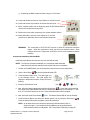
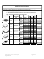
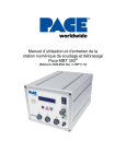
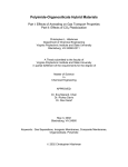
ST 350 REFLOW PROFILES
SUGGESTED STARTING PARAMETERS
This chart provides a base starting point for the development of exact parameters ("Established Profile Guidelines") for your surface
mount rework process. Initial tests using these references may not result in complete solder reflow. Adjust the reference values as
necessary to obtain desired results. All results should be verified/validated through the use of thermocouples.
Procedure: 1.
2.
3.
4.
Select the Component and Substrate which best matches your application.
Perform a test using the base parameters.
Adjust parameters as desired and perform additional test runs.
When desired results are achieved, record process on a copy of Profile Control Chart or Profile Log.
NOTE: Blower Speed parameter is base reference for Reflow function.
Component
Nozzle
Process
Parameter
Remove
(Temperature
Recommended
Outline
Type
or
and Blower
Type
Install
Speed)
Temperature
Remove
(°C)
Appropriate Size
Blower Speed
PBGA
V-A-N Nozzle
Temperature
Install
(°C)
Blower Speed
Temperature
Remove
(°C)
PLCC
Appropriate Size
Blower Speed
Box Nozzle
Temperature
(J Lead)
Install
(°C)
Blower Speed
Temperature
Remove
(°C)
Blower Speed
Appropriate Size
PQFP
Temperature
Box Nozzle
(°C)
Install
Blower Speed
Remove
SOIC
Appropriate Size
Pattern Nozzle
Install
Remove
Chip
Component
Appropriate Size
Single Jet Nozzle
Install
©2004 PACE Inc., Annapolis Junction, Maryland
All Rights Reserved
Temperature
(°C)
Blower Speed
Temperature
(°C)
Blower Speed
Temperature
(°C)
Blower Speed
Temperature
(°C)
Blower Speed
Substrate (PCB Type)
Medi
Low
High
um
Mass
Mass
Mass
371
371
371
5
5
5
371
371
371
3
3
4
371
371
371
7
8
8
371
371
371
7
8
8
316
371
371
6
7
7
316
371
371
6
7
7
316
316
371
7
7
7
316
316
371
7
7
7
371
371
371
6
6
8
371
371
371
5
6
7
Reflow Cycle
Time (sec.)
77
90
30
30
18
18
Page 32 of 45
15
15
11
12
Profile Control Chart
Duplicate this page and complete the copied form. DO NOT fill out the copy in this manual.
PROGRAM MODE PROFILE CONTROL CHART
Component
PCB Designation:
Temp. Scale:
Preheat
Yes
No
Lower Preheat
Yes
No
F C
Profile #
Process: Remove Install
Top Preheat
Yes
No
Time
Time
Temp.
Temp.
Start
(sec.)
Blower Speed
Soak
Yes
No
Time
Reflow
Yes
(sec.)
Cool Down
Blower Speed
No
Time
(Install Only)
Temp.
Temp.
(sec.)
Blower Speed
Vacuum Release
On
Lower Pump
Blower Speed
Off
Approved By:
Off
Time
On
(sec.)
Date:
Comments / Instructions:
©2004 PACE Inc., Annapolis Junction, Maryland
All Rights Reserved
Page 33 of 45
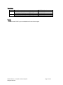
Profile Log
Duplicate this page and complete the copied form. DO NOT fill out the copy in this manual.
PCB
Designation
Component
Process
(Remove
or
Install)
Mode
©2004 PACE Inc., Annapolis Junction, Maryland
All Rights Reserved
Profile
#
Set
Temperature
Blower
Speed
CycleTime
(sec.)
Page 34 of 45
Preheating
Required
General Process Guidelines
Board Preparation
Prepare the land pattern as per your company specifications. The most widely used methods are as
follows:
1. Prefill - The PCB land pattern is prefilled using a soldering iron. Care must be taken to insure that
all lands are tinned with an equal deposition of solder (provides a uniform appearance).
2. Solder Paste - Apply an equal amount of solder paste on each land. Take care to insure that the
proper amount of paste is dispensed. If too much paste is applied, solder bridges will form
between the lands. If an insufficient amount of paste is applied, solder joint formation will be
unacceptable (open/starved joints). The PCB assembly (or rework area) should also be
preheated (in accordance with your company requirements) after solder paste deposition to
remove any volatiles (e.g., solvents) in the paste. The PACE ST 400 & ST 450 systems are highly
recommended for this preheating application. Preheating can also be accomplished with top
heat.
Component Positioning
The ST 350 has the capability of placing many SMD components properly. In some instances (e.g., fine
pitch FlatPack placement) however, the user may prefer to position a component and solder tack it in
place prior to final soldering. The following procedure is extremely useful when installing leaded
components.
1. Using a PACE Pik-Vac (vacuum holding device) or tweezers for handling or holding, position the
component leads to align with the land areas.
NOTE: A flux paste may be applied to corners of the PCB land pattern to temporarily hold the
component in place.
2. Using a soldering iron with a fine pointed tip, tack two or more lead to land locations at opposite
corners of the component. This will provide stability during subsequent handling throughout the
soldering process.
Preheating
Preheating of a printed circuit assembly is recommended in the repair process when one or more of the
following situations exist.
1. Epoxy glass substrate with 4 or more layers.
2. Substrate with large ground planes.
3. Substrate of ceramic, polyimide or other high heat dissipative material.
4. Printed circuit assembly with large metal heat sinks.
Preheating of assemblies such as those listed above will accomplish the following objectives.
1. Minimize thermal shock by elevating the assembly temperature to a level closer to solder melt
temperature.
2. Minimize the heat cycle reflow time.
©2004 PACE Inc., Annapolis Junction, Maryland
All Rights Reserved
Page 35 of 45
3. Overcome the heat dissipation characteristics of the assembly.
4. Minimize adjacent reflows.
The assembly undergoing repair must be heated for a length of time sufficient to saturate at the preheat
temperature required. The PCB preheat temperature normally used is 100°C (212°F) for epoxy glass
substrates and 120°C (248°F) for ceramics and polyimides.
Although many different methods such as ovens and bottom side preheaters may be utilized to
accomplish the required results, the user must employ a method which heats the assembly as evenly as
possible and can be employed with the ST 350 unit. The preheat temperature should also be maintained
throughout the Removal/Replacement process. PACE recommends the use of it’s ST 400 or ST 450 Preheating systems for this purpose.
Corrective Maintenance
Display Error Messages
Listed below are message codes which may be displayed on the Digital Readout if a mistake is made by
the operator (e.g., wrong password entry) or if the system has malfunctioned.
Display Error Message
Wrong Password
Description
The incorrect Password has been entered. The
displayed message will time out after 3 seconds and
revert to normal operation. Enter the correct
Password.
Open Sensor
The heater assembly sensor is open.
Replace heater assembly.
Blower Run Error
The power source blower unit is not running. Contact
PACE for assistance.
Power Source/Handpiece
Refer to the table below. Most malfunctions are simple and easy to correct.
Symptom
No power to system
Heater Assembly does
not heat. No
malfunction indicated
on Digital Readout.
Little or no air flow,
heater heats and
blower is running
Probable Cause
Blown Fuse
Line cord
unplugged
Open Heater
Kinked air hose
©2004 PACE Inc., Annapolis Junction, Maryland
All Rights Reserved
Solution
Inspect and replace the fuse(s) located on the
power source rear panel.
Plug line cord into the appropriate AC outlet.
Contact PACE for assistance.
Change routing of air hose to remove
kinks.
Page 36 of 45
Display on Digital
Readout indicates a
malfunction.
Little or no vacuum
Refer to Display Error Messages.
Vacuum Cup will not
hold component
Worn vacuum
pump
Worn or broken
vacuum cup
Replace vacuum pump. Contact PACE for
assistance.
Replace vacuum cup.
Vacuum Pickup Rod
binding
Vacuum Pickup
rod is bent
Refer to the Vacuum Pick Replacement on Page
37.
Vacuum Pick Replacement
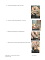
Removal
1. Turn the knob counterclockwise to remove it from the shaft. Hold the
shaft when loosening in order to keep the shaft from rotating.
2. Remove the vacuum hose.
3. Remove the Pick Shroud. (Requires a 9/64” hex key).
2 hex socket
head screws
©2004 PACE Inc., Annapolis Junction, Maryland
All Rights Reserved
Page 37 of 45
4. Carefully lift the Pick Shroud from the Reflow Head Assembly.
5. Make sure that the Theta Knob is centered as shown.
Must be
pointing up.
6. Remove the Theta Knob Assembly. (Requires a 9/64” hex key).
2 hex socket head
screws
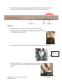
7. Loosen the vacuum pick with a 7/32” open-end wrench.
NOTE:
Failure to hold the manifold
assembly may result in damage to
the vacuum tube.
©2004 PACE Inc., Annapolis Junction, Maryland
All Rights Reserved
Hold the
manifold to keep
the assembly
from rotating
Page 38 of 45
8. Carefully lift the assembly from the vacuum tube.
9. Remove the 3 button head screws with a 1/16” hex key.
10. Gently lift the Beveled Gear from the Reflow Head.
11. Carefully remove the vacuum tube assembly from the Reflow Head.
©2004 PACE Inc., Annapolis Junction, Maryland
All Rights Reserved
Page 39 of 45
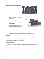
12. Remove the E-Clip and slide the Springs and Gear Rack from the Vacuum Tube. With the
exception of the Vacuum Tube, these parts will be reused on the new Vacuum Tube.
Springs
Vacuum Tube
E-Clip
Gear Rack
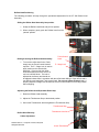
Installation
1. Install the Springs, Gear Rack, and E-Clip on the new Vacuum Tube.
2. Insert the Vacuum Tube Assembly into the Reflow Head. Be sure to face the
teeth of the Gear Rack to the front.
3. Use the Vacuum Pick Control Knob to verify engagement of the Vacuum Tube Assembly.
Vacuum
Pick Control
Knob
4. Install the Beveled Gear. Install and tighten the three button
head screws with a 1/16” hex key. Must be snug but do not over
tighten!
©2004 PACE Inc., Annapolis Junction, Maryland
All Rights Reserved
Page 40 of 45
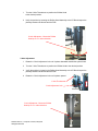
5. Insert the Manifold Vacuum Assembly and tighten the vacuum pick
with a 7/32” open-end wrench. Must be snug but do not over
tighten!
6. Before installing the Theta Knob Assembly, be sure to properly line up the Vacuum Pick Control
Knobs.
Knob axis centerline
Make sure that the knobs are
parallel to the Reflow Head
Mounting Heat Mounting Plate.
7. Install the Theta Knob Assembly.
Install the Theta
Knob Assembly.
(Requires a 5/64”
hex key).
Theta Knob
must be
pointing up.
NOTE: It is also possible to adjust the Theta Knob by adjusting its position on the shaft.
This will require a 5/64” hex key to loosen the two setscrews.
2 Set
Screws
©2004 PACE Inc., Annapolis Junction, Maryland
All Rights Reserved
Page 41 of 45
8. Carefully install the Pick Shroud onto the Reflow Head Assembly. Make sure that the Vacuum
Pick moves freely when turning the Vacuum Pick Control Knob.
9. Install the vacuum hose.
10. Turn the knob clockwise to install it on the shaft. Hold the shaft when tightening in order to keep
the shaft from rotating.
11. Verify proper operation.
Packing List
Item #
1
2
3
4
5
6
7
8
9
10
Description
Part Number
System Power Supply
System Power Supply (Export)
Power Cord, 115V
Power Cord, 230V
PV-65 Handpiece
Nozzle Adapter
PCB Support
PCB Fingers
Hot Grip Removal Pad
Operations Manual CD
8007-0437
8007-0438
1332-0094
1332-0093
7027-0001-P1
4028-0001-P1
6000-0287-P1
1100-0307-P1
CD5050-0459
©2004 PACE Inc., Annapolis Junction, Maryland
All Rights Reserved
ST 350
Only
1
0
1
0
1
1
1
4
1
1
ST 350 E
Only
0
1
0
1
1
1
1
4
1
1
Page 42 of 45
Spare Parts
Item #
1
2
Description
Fuse, 7 Amp, 125 V, Fast Acting (ST 350)
Fuse, 5 Amp, 250 V, Fast Acting (ST 350E)
Fuse, 0.5 Amp, 125 V, Time Lag (ST 350)
Fuse, 0.5 Amp, 250 V, Time Lag (ST 350E)
PACE Part Number
1159-0274-P5
1159-0266-P5
1159-0248-P5
1159-0213-P5
Service
Please contact PACE or your local distributor for service and repair.
©2004 PACE Inc., Annapolis Junction, Maryland
All Rights Reserved
Page 43 of 45
PACE Incorporated retains the right to make changes to specifications contained herein at any time,
without notice. Contact your local authorized PACE Distributor or PACE Incorporated to obtain the latest
specifications.
The following are trademarks and/or service marks of PACE, Incorporated, MD, USA:
INSTACAL™, FUMEFLO™, HEATWISE™, PACEWORLDWIDE™, PERMAGROUND™,
POWERPORT™, POWERMODULE™, TEMPWISE™, TIP-BRITE™, AUTO-OFF™, and
TEKLINK™.
The following are registered trademarks and/or service marks of PACE Incorporated, Annapolis Junction
Maryland U.S.A.
ARM-EVAC®, FLO-D-SODR®, MINIWAVE®, PACE®, SENSATEMP®, SNAP-VAC®,
SODRTEK®, SODR-X-TRACTOR®, ST 350®, THERMOJET®, THERMOTWEEZ®,
VISIFILTER®, THERMO-DRIVE®, and TOOLNET®.
PACE products meet or exceed all applicable military and civilian EOS/ESD, temperature stability and
other specifications including MIL STD 2000, ANSI/JSTD 001, IPC7711, and IPC A-610.
www.paceworldwide.com
PACE USA
9030 Junction Drive
Annapolis Junction, MD 20701
USA
PACE Europe
Sherbourne House
Sherbourne Drive
Tilbrook, Milton Keynes
MK7 8HX
United Kingdom
Tel:
(301) 490-9860
(44) 01908-277666
Fax:
(301) 498-3252
(44) 01908-277777
©2004 PACE Inc., Annapolis Junction, Maryland
All Rights Reserved
Page 45 of 45